EP2271073A2 - Procédés de thermographie - Google Patents
Procédés de thermographie Download PDFInfo
- Publication number
- EP2271073A2 EP2271073A2 EP10251182A EP10251182A EP2271073A2 EP 2271073 A2 EP2271073 A2 EP 2271073A2 EP 10251182 A EP10251182 A EP 10251182A EP 10251182 A EP10251182 A EP 10251182A EP 2271073 A2 EP2271073 A2 EP 2271073A2
- Authority
- EP
- European Patent Office
- Prior art keywords
- thermal image
- area
- image
- visible light
- presented
- Prior art date
- Legal status (The legal status is an assumption and is not a legal conclusion. Google has not performed a legal analysis and makes no representation as to the accuracy of the status listed.)
- Granted
Links
- 238000000034 method Methods 0.000 title claims abstract description 53
- 238000001931 thermography Methods 0.000 title description 12
- 230000002452 interceptive effect Effects 0.000 claims abstract description 21
- 238000002156 mixing Methods 0.000 claims description 4
- 238000012544 monitoring process Methods 0.000 description 15
- 230000002093 peripheral effect Effects 0.000 description 8
- 230000003213 activating effect Effects 0.000 description 4
- 238000004458 analytical method Methods 0.000 description 4
- 230000005855 radiation Effects 0.000 description 4
- 230000004927 fusion Effects 0.000 description 3
- 238000013461 design Methods 0.000 description 2
- 241000935974 Paralichthys dentatus Species 0.000 description 1
- 230000004913 activation Effects 0.000 description 1
- 238000011161 development Methods 0.000 description 1
- 238000003708 edge detection Methods 0.000 description 1
- 230000008571 general function Effects 0.000 description 1
- 238000007689 inspection Methods 0.000 description 1
- 238000012423 maintenance Methods 0.000 description 1
- 238000012986 modification Methods 0.000 description 1
- 230000004048 modification Effects 0.000 description 1
- 238000005457 optimization Methods 0.000 description 1
Images


Classifications
-
- G—PHYSICS
- G01—MEASURING; TESTING
- G01J—MEASUREMENT OF INTENSITY, VELOCITY, SPECTRAL CONTENT, POLARISATION, PHASE OR PULSE CHARACTERISTICS OF INFRARED, VISIBLE OR ULTRAVIOLET LIGHT; COLORIMETRY; RADIATION PYROMETRY
- G01J5/00—Radiation pyrometry, e.g. infrared or optical thermometry
- G01J5/02—Constructional details
- G01J5/025—Interfacing a pyrometer to an external device or network; User interface
-
- H—ELECTRICITY
- H04—ELECTRIC COMMUNICATION TECHNIQUE
- H04N—PICTORIAL COMMUNICATION, e.g. TELEVISION
- H04N23/00—Cameras or camera modules comprising electronic image sensors; Control thereof
- H04N23/10—Cameras or camera modules comprising electronic image sensors; Control thereof for generating image signals from different wavelengths
- H04N23/11—Cameras or camera modules comprising electronic image sensors; Control thereof for generating image signals from different wavelengths for generating image signals from visible and infrared light wavelengths
-
- H—ELECTRICITY
- H04—ELECTRIC COMMUNICATION TECHNIQUE
- H04N—PICTORIAL COMMUNICATION, e.g. TELEVISION
- H04N23/00—Cameras or camera modules comprising electronic image sensors; Control thereof
- H04N23/60—Control of cameras or camera modules
- H04N23/63—Control of cameras or camera modules by using electronic viewfinders
- H04N23/633—Control of cameras or camera modules by using electronic viewfinders for displaying additional information relating to control or operation of the camera
- H04N23/635—Region indicators; Field of view indicators
-
- H—ELECTRICITY
- H04—ELECTRIC COMMUNICATION TECHNIQUE
- H04N—PICTORIAL COMMUNICATION, e.g. TELEVISION
- H04N5/00—Details of television systems
- H04N5/30—Transforming light or analogous information into electric information
- H04N5/33—Transforming infrared radiation
-
- G—PHYSICS
- G01—MEASURING; TESTING
- G01J—MEASUREMENT OF INTENSITY, VELOCITY, SPECTRAL CONTENT, POLARISATION, PHASE OR PULSE CHARACTERISTICS OF INFRARED, VISIBLE OR ULTRAVIOLET LIGHT; COLORIMETRY; RADIATION PYROMETRY
- G01J5/00—Radiation pyrometry, e.g. infrared or optical thermometry
- G01J2005/0077—Imaging
Definitions
- the present invention pertains to thermography and more particularly to methods for presenting a thermal image within a visible light image.
- Thermal images of systems that include electrical and/or mechanical devices and structures can be useful for monitoring and/or analyzing the performance thereof, both during design and development, for example, for design optimization purposes, and during operational service, for example, for inspection and maintenance purposes.
- the thermal, or infrared images may be captured and displayed by an infrared (IR) camera module of a thermography system; the IR camera module may include a focal plane array (FPA) of microbolometers, for capturing IR radiation, and electronics which are adapted to convert the captured IR radiation to temperature data, and then to scale and map the temperature data to an array of pixels, wherein a color, or a gray-scale value, of each pixel corresponds to a detected temperature, or temperature range.
- FPA focal plane array
- thermography systems have been developed to include a visible light (VL) camera module in conjunction with the IR camera module, so that thermal images can be merged with corresponding visible light images in order to provide a more tangible/structural context for the thermal images.
- VL visible light
- Those skilled in the art call this merging of images 'fusion', and methods for fusion are known in the art, for example, being described in commonly assigned U.S. patent application publication US 2008/0099678 .
- a variety of methods for presenting a thermal image fused with a corresponding visible light image are known in the art, one example of which is known as FLIR Triple FusionTM, wherein an infrared image may be moved, resized and reshaped inside a visible light image.
- FLIR Triple FusionTM wherein an infrared image may be moved, resized and reshaped inside a visible light image.
- a method for presenting a thermal image of a scene within a visible light image of the scene comprising:
- a method for presenting a thermal image of a scene within a visible light image of the scene comprising:
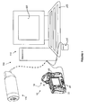
- FIG 1 is a schematic overview of an exemplary thermography system 100, with which methods of the present invention may be employed.
- Figure 1 illustrates a handheld-type camera 10, for example to take still images, and a monitoring-type camera 175 designed to be mounted for monitoring at a fixed location, for example, to take still and/or video images.
- Each of cameras 10, 175 includes an IR camera module and a VL camera module.
- the IR camera module of camera 10 includes a focus ring 16, for focusing an IR lens (not shown) of camera 10, and an IR sensor assembly (not shown), for example, a microbolometer focal plane array, which is aligned with the IR lens that is focused with ring 16 to receive IR radiation from a scene toward which the lens is pointed, or directed; and the visible light (VL) camera module of camera 10 may be located in the region to which arrow 18 points.
- Electronics that are included in each of the cameras 10, 175 have the capability to convert the raw IR radiation to digital temperature data, and then to correct, map and scale the data for display as a thermal image fused with a VL image, captured by the VL camera module, according to methods known in the art.
- FIG. 1 further illustrates a workstation 110, for example, a personal computer, which may be connected to one or both of cameras 10, 175.
- a thermography software program which is loaded in one or both of camera 10 and workstation 110, in conjunction with peripheral tools, such as buttons 22 of camera 10 and/or mouse 105 and key board 103 of workstation 110, can be used to manipulate the display/presentation of the captured thermal images fused with the captured VL images on one or both of a display 20 of camera 10 and a display 120 of workstation 110, according to methods of the present invention.
- the term 'image' may be used broadly for both still and video images.
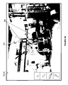
- Figures 2A-B are exemplary, prior art, fused thermal and VL picture-in-picture type images 200, 210 of a scene within a chilling station.
- Figure 2A illustrates a thermal image 205 presented within, and filling, a predetermined area of a VL image 203 of the scene; the area has been selected in order to direct a viewer's attention to one or more particular physical objects of interest within the scene, for example, including a pipe whose ends are marked with temperature readings in Figure 2A .
- Thermal image 205 is wholly composed of gray-scale coding (originally composed of color coding), which overlays the VL image 203 in the predetermined area and corresponds to a measured temperature distribution of every object within the predetermined area.
- Figure 2B illustrates a thermal image 215 blended with VL image 203 in a predetermined area of VL image 203, which also encompasses the aforementioned pipe, wherein an extent of the gray-scale coding (originally color coding) is limited according to at least one temperature threshold criterion, such that only those portions of thermal image 215, which meet the criterion, are presented within the area.
- Methods for presenting/displaying thermal images according to these alternative characteristics are known to those skilled in the art.
- a blending of thermal and VL images is described in the aforementioned commonly-assigned '678 patent application publication as alpha-blending, and a limited presentation of a thermal image, which is based on a temperature threshold criterion, is described in the same publication as a color-alarm.
- the selected areas although significantly smaller than an entire area of VL image 203, still encompass portions of the captured scene within the chilling station, in addition to the object(s) of interest, from which temperature information is not necessarily required for monitoring and/or analysis.
- previously disclosed methods for example, as referred to in the Background of the present disclosure, allow for moving, resizing and reshaping the areas of thermal images 205, 215 within VL image 203, for alternative configurations of picture-in-picture type images 200, 210, the shape of these selected areas have heretofore been somewhat limited.
- an area for a presentation of a thermal image, within a VL image is established to have a perimeter edge that corresponds in shape to an identified outline of a physical object of interest, for example, as illustrated in Figures 3A-B .
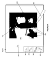
- Figure 3A is a schematic representation of one of displays 20, 120 of thermography system 100 ( Figure 1 ), on which VL image 203 is presented along with some interactive elements of a graphical user interface of the system, for accomplishing methods of the present invention. It should be noted that the interactive elements, as well as peripheral tools of system 100, as described below, are known to those skilled in the art.
- Figure 3A illustrates a touch screen 340 as an interactive element for use in conjunction with a stylus 360, and a cursor 345 as an interactive element, which may be activated by stylus 360, buttons 22, mouse 105 and/or keyboard 103 ( Figure 1 ); optional drawing tools 351, 353, 355, 357, the general functions of which are performed by similar interactive elements of commercially available software packages (i.e.
- Figure 3A further illustrates perimeter edges 315 and 325 (shown with dashed lines) of a selected area that corresponds to a first object of interest 310 and a second object of interest 320.
- the display of VL image 203 is viewed in order to identify an outline 312, 322 of each of first and second objects 310, 320, and, then, one or more of interactive elements 340, 345, 350 may be employed to select the area defined by perimeter edges 315, 325.
- a thermal image of the objects of interest 310, 320 is presented/displayed within the selected area, either during the selection or immediately following the selection. It should be noted that, alternatively, an area corresponding to either a single object of interest, or to more than two objects of interest, may be selected for a thermal image presented within a given VL image, and multiple objects of interest may overlap one another within the VL image.
- a peripheral tool, or input device such as stylus 360 or a finger, is placed in contact with touch screen 340 at one or more points along one or both of identified outlines 312, 322, in order to surround and, thereby, select the area, in which the thermal image will be presented, or is placed in contact with one or more points within one or both of identified outlines 312, 322, in order to fill in and, thereby, select the area.
- another type of peripheral tool/input device such as buttons 22 (i.e. if VL image is being viewed on display 20 of camera 10) or mouse 105 and/or keyboard 103 (i.e.
- VL image is being viewed on display 120 of workstation 110
- drawing tools 351, 353, 355, 357 may be chosen, for example, using any one of the peripheral tools/input devices mentioned above, to select the area in one of the above-described manners.
- Drawing tool 351 which has a relatively fine point, for example, corresponding to a single pixel of VL image 203, may be used to select points along one or both of outlines 312, 322, for example, by activating tool 351 and moving the fine point thereof along outlines 312, 322 in order to select the corresponding area, while drawing tool 353, which has a relatively broader point, may be used to select points within one or both of outlines 312, 322, for example, by activating tool 353 and moving the broader point thereof to fill in and thereby select the corresponding area.
- Drawing tool 355 which is depicted in the form of a lasso, is adapted to 'snap' to edges of contrast, for example, like those edges that, at least in part, define outlines 312 and 322 of objects 310 and 320, respectively, in VL image 203.
- a user may select the area within outlines 312, 322 by merely moving tool 355 into close proximity with a point on each outline 312, 322 and activating tool 355; upon activation, tool 355 will snap to the point on the edge of contrast and cling to the edge of contrast for selection of the corresponding area that is contained therein.
- Drawing tool 357 which is depicted in the form of a magic wand, is adapted to automatically select all neighboring pixels that are similar to one that is manually selected, with tool 357, by the user.
- the user may select at least a portion of area within outlines 312 and 322 of respective objects 310, 320, by merely moving tool 357 over a single point/pixel of each object 310, 320 and activating tool 357.
- the user of tools 355 and 357 may change the tolerances thereof according to contrast and/or color characteristics of the captured objects of interest, for example, objects of interest 310, 320 in VL image 203.
- each of perimeter edges 315, 325 of the selected area correspond in shape to the corresponding identified outline 312, 322 of objects 310, 320, so as to isolate these objects from the rest of the scene captured in VL image 203.
- perimeter edges 315, 325 need not exactly overlay identified outlines 312, 322, but may fall alongside the outlines, one side or the other, in close proximity thereto so as to closely match the shape thereof.
- objects of interest 310, 320 are shown as separate sections of pipes, or ducts, in Figures 3A-B , it should be appreciated that, according to methods of the present invention, an object of interest is not so limited, and may, for example, include an entire single component within a captured scene or an assembly of components within a captured scene.
- Figure 3B illustrates thermal image 392 having a characteristic similar to that of thermal image 205, that is, being wholly composed of gray-scale coding corresponding to the measured temperature distribution of objects of interest 310, 320.
- thermal image 392 may be blended with the corresponding portion of VL image 203, and/or limited by at least one temperature threshold criterion, similar to thermal image 215 shown in Figure 2B .
- certain characteristics, for the presentation of the thermal image within the selected area of the corresponding VL image may be established either prior to or after selecting the area.
- Figure 4A shows a step 411 in which the capture of a thermal image and VL image, for display, precedes a step 413 in which the displayed VL image is viewed, and a step 415 in which an outline of each physical object of interest in the displayed VL image is identified.
- step 417 the user selects the corresponding area on the displayed VL image, for presenting/displaying the thermal image, per step 417.
- the flow chart of Figure 4B outlines some alternative methods wherein initial steps 430, 432, 434 and 436 generally correspond to steps 411, 413, 415 and 417 of Figure 4A , with the exceptions that capturing the thermal image, for display, per step 438, follows selecting the area, per step 436, and step 436 further includes storing the selected area in a memory of the thermography system.
- any of the means described above, in conjunction with Figure 3A , for selecting the area, on the displayed VL image, for the presentation of the thermal image, may be employed in steps 417, 436 of Figures 4A-B .
- a step of establishing at least one characteristic for the presentation of the thermal image, prior to presenting the thermal image (419, 440) may be included in the methods outlined in Figures 4A-B , for example, in conjunction with selecting the area (417, 436).
- the camera and objects of interest may need to remain approximately stationary with respect to one another during the time that spans steps 430-438. If an object of interest is a moving part within a scene captured by the camera, for example, a robotic arm that is being monitored by the camera, the camera may have motion and or edge detection capability to re-map the corresponding selected area while the object moves within the scene, in order to facilitate capturing the corresponding thermal image, per step 438, at different times.
- step 436 includes storing the selected area in memory, so that when the thermal image is later captured, for example, during a monitoring period, the thermal image will only be presented/displayed within the selected area.
- the thermal image may be one of a series of thermal images that have been collected to document a thermal history of each object of interest, defined by the selected area, over the time of the monitoring period.
- Each thermal image, captured at step 438 may have been stored in the memory with a time stamp, for identification, and then presented, in sequence, for later viewing, per step 440; and, if a predetermined temperature threshold criterion has been established, then only those thermal images that meet the threshold criterion may be presented.
- a monitoring camera having video capability for example, camera 175 ( Figure 1 )
- Video data may also be stored, for example, in standard video files (i.e. mpeg4 or h.264 encoded) or in proprietary radiometric video files, for viewing at a later time.
- the steps of the method outlined in Figure 4B may be accomplished with a combination of still and video images, wherein presenting, per step 440 of Figure 4B , and per step 419 of Figure 4A , can take place in real time or at a later time, and the presented thermal image may be a video image or a series of still images that span a monitoring period.
- the thermal image may appear on the system display while the area in the VL image is being selected.
- the thermal image may progressively appear along, or alongside, a trail of the drawing tool.
- an entirety of the thermal image may appear immediately following completion of the selection of the area corresponding to each object of interest.
- the thermal image presented/displayed in step 419 is one of a series of thermal images that have been stored in the memory of the thermography system, and these images may be presented in sequence, for viewing, per step 419.
- a predetermined temperature threshold criterion has been established, then only those thermal images that meet the threshold criterion will be presented.
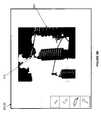
- Figure 5A is schematic representation of one of displays 20/120 of thermography system 100 ( Figure 1 ), wherein a captured thermal image 500 of a scene that includes a substation transformer is presented, along with the previously described interactive elements of the graphical user interface of system 100, which may facilitate additional methods of the present invention.
- Figure 5A illustrates the interactive elements: touch screen 340, stylus 360, cursor 345 and optional drawing tools 351, 353, 355, 357 all of which were described, above, in conjunction with Figure 3A .
- Figure 5A further illustrates thermal image 500 including an identified area of interest 510, which corresponds to a particular physical part of the scene/substation transformer, along with other area 590, which is outlined with dashed lines.
- FIG. 5B is a schematic representation of display 20/120, on which the presentation of thermal image 500 has been modified to only include area of interest 510.
- Other area 590 of thermal image 500 have been removed in order to display VL image 503 of the remaining parts of the substation transformer that correspond to other area 590.
- Figure 6 is a flow chart outlining the additional methods of the present invention, which may correspond to Figures 5A-B .
- Figure 6 illustrates an initial step 511 in which thermal and VL images are captured, for display, prior to viewing the displayed thermal image, per step 513.
- the user identifies area of interest, per step 515, and then selects another area, which is separate from the identified area of interest, per step 517.
- the other area of the thermal image is removed so that corresponding portions of the VL image are displayed.
- selection, per step 517 is made by placing a peripheral tool, or input device, such as stylus 360 or a finger, in contact with touch screen 340 at one or more points along a perimeter, or perimeters, of the area of the displayed thermal image that is separate from the area of interest, for example, the perimeters of each portion of area 590, which is designated by the dashed lines.
- the device is positioned over one or more points within the perimeter of the other area, for example, within one of the dashed lines surrounding area 590, to select the other area.
- another type of peripheral tool/input device such as buttons 22, shown in Figure 1 (i.e.
- thermal image is being viewed on display 20 of camera 10
- mouse 105 and/or keyboard 103 also shown in Figure 1 (i.e. if the thermal image is being viewed on display 120 of workstation 110)
- cursor 345 is activated to position cursor 345 at one or more points on or within a perimeter of the area of the thermal image that is separate from the area of interest.
- drawing tools 351, 353, 355, 357 may be chosen, for example, using any one of the peripheral tools/input devices mentioned above, to select the other area in one of the above-described manners.
Landscapes
- Engineering & Computer Science (AREA)
- Multimedia (AREA)
- Signal Processing (AREA)
- Physics & Mathematics (AREA)
- General Physics & Mathematics (AREA)
- Spectroscopy & Molecular Physics (AREA)
- Human Computer Interaction (AREA)
- Radiation Pyrometers (AREA)
- Image Processing (AREA)
- Investigating Or Analyzing Materials Using Thermal Means (AREA)
Applications Claiming Priority (1)
| Application Number | Priority Date | Filing Date | Title |
|---|---|---|---|
| US22218609P | 2009-07-01 | 2009-07-01 |
Publications (3)
| Publication Number | Publication Date |
|---|---|
| EP2271073A2 true EP2271073A2 (fr) | 2011-01-05 |
| EP2271073A3 EP2271073A3 (fr) | 2014-01-22 |
| EP2271073B1 EP2271073B1 (fr) | 2018-03-07 |
Family
ID=42989189
Family Applications (1)
| Application Number | Title | Priority Date | Filing Date |
|---|---|---|---|
| EP10251182.1A Active EP2271073B1 (fr) | 2009-07-01 | 2010-06-30 | Procédés de thermographie |
Country Status (3)
| Country | Link |
|---|---|
| US (1) | US9232142B2 (fr) |
| EP (1) | EP2271073B1 (fr) |
| CN (1) | CN101945224B (fr) |
Cited By (5)
| Publication number | Priority date | Publication date | Assignee | Title |
|---|---|---|---|---|
| EP2477391A1 (fr) * | 2011-01-17 | 2012-07-18 | Research In Motion Limited | Affichage à réalité augmentée thermographique dans un dispositif électronique |
| EP2803963A4 (fr) * | 2012-01-12 | 2015-09-30 | Mission Infrared Electro Optics Technology Co Ltd | Dispositif d'imagerie thermique et procédé de prise d'image thermique normalisée |
| EP2803964A4 (fr) * | 2012-01-12 | 2016-01-27 | Mission Infrared Electro Optics Technology Co Ltd | Dispositif pour image thermique et procédé de prise d'image thermique |
| EP2964449B1 (fr) | 2013-03-06 | 2018-05-30 | MTU Aero Engines GmbH | Procédé et dispositif pour évaluer la qualité d'un composant fabriqué au moyen d'un procédé génératif de frittage au laser et/ou de fusion au laser |
| US10032283B2 (en) | 2014-10-23 | 2018-07-24 | Axis Ab | Modification of at least one parameter used by a video processing algorithm for monitoring of a scene |
Families Citing this family (52)
| Publication number | Priority date | Publication date | Assignee | Title |
|---|---|---|---|---|
| US8373758B2 (en) * | 2009-11-11 | 2013-02-12 | International Business Machines Corporation | Techniques for analyzing performance of solar panels and solar cells using infrared diagnostics |
| JP2011211493A (ja) * | 2010-03-30 | 2011-10-20 | Sony Corp | 撮像装置、表示方法及びプログラム |
| KR101357262B1 (ko) * | 2010-08-13 | 2014-01-29 | 주식회사 팬택 | 필터 정보를 이용한 객체 인식 장치 및 방법 |
| DE102010048022B4 (de) * | 2010-10-09 | 2013-08-14 | Testo Ag | Verfahren zur berührungslosen Bestimmung der Temperatur eines Objekts und korrespondierende Wärmebildkamera |
| KR101246918B1 (ko) * | 2011-09-08 | 2013-03-25 | 유덕봉 | 비접촉식 온도 감시 장치 |
| US20170296065A9 (en) * | 2012-04-04 | 2017-10-19 | James G. Spahn | Method of Monitoring the Status of a Wound |
| US20170296064A9 (en) * | 2012-04-04 | 2017-10-19 | Spahn James G | Method of Monitoring The Status of A Wound |
| JP5772272B2 (ja) * | 2011-06-16 | 2015-09-02 | 富士通株式会社 | 情報処理装置、及び情報処理方法 |
| US20120320189A1 (en) * | 2011-06-20 | 2012-12-20 | Fluke Corporation | Thermal imager that analyzes temperature measurement calculation accuracy |
| US10965889B2 (en) | 2011-06-20 | 2021-03-30 | Fluke Corporation | Thermal imager that analyzes temperature measurement calculation accuracy |
| CN102980662A (zh) * | 2011-09-07 | 2013-03-20 | 台达电子工业股份有限公司 | 温度检测系统及温度检测方法 |
| WO2013123951A1 (fr) * | 2012-02-21 | 2013-08-29 | Testo Ag | Procédé et dispositif de mesure pour réaliser un résultat de mesure 3d résolu en position dans une plage spectrale non visible |
| US20160027172A1 (en) | 2012-04-04 | 2016-01-28 | James G. Spahn | Method of Monitoring the Status of a Wound |
| CN108848299B (zh) * | 2012-05-23 | 2021-05-11 | 杭州阿尔法红外检测技术有限公司 | 热像摄影装置和热像摄影方法 |
| CN103458175B (zh) * | 2012-05-23 | 2018-08-03 | 杭州阿尔法红外检测技术有限公司 | 热像记录装置和热像记录方法 |
| CN103458176B (zh) * | 2012-05-23 | 2018-05-22 | 杭州阿尔法红外检测技术有限公司 | 热像拍摄装置和热像拍摄方法 |
| US9198496B2 (en) * | 2012-07-02 | 2015-12-01 | Sony Corporation | Makeup TV |
| US9413988B2 (en) * | 2012-07-24 | 2016-08-09 | Fluke Corporation | Thermal imaging camera with graphical temperature plot |
| US9305366B2 (en) * | 2012-08-08 | 2016-04-05 | Jeffrey Stark | Portable electronic apparatus, software and method for imaging and interpreting pressure and temperature indicating |
| CN103674253A (zh) * | 2012-09-21 | 2014-03-26 | 杭州美盛红外光电技术有限公司 | 热像显示控制装置和热像显示控制方法 |
| US9324138B2 (en) | 2013-03-15 | 2016-04-26 | Eric Olsen | Global contrast correction |
| KR101504523B1 (ko) * | 2013-05-23 | 2015-03-20 | 삼성전자 주식회사 | 의료 진단 시스템 제어 방법, 피검사자의 영상 제공 방법 및 이를 위한 의료 진단 시스템 제어 장치 |
| US9681066B2 (en) * | 2013-07-08 | 2017-06-13 | Flir Systems Ab | Facilitating improved calibration of captured infrared data values by an IR imaging system in a thermography arrangement |
| US9878804B2 (en) * | 2013-10-21 | 2018-01-30 | Eric Olsen | Systems and methods for producing temperature accurate thermal images |
| CN104655289B (zh) * | 2013-11-25 | 2021-11-09 | 杭州美盛红外光电技术有限公司 | 分析区域设置装置、处理装置和分析区域设置方法、处理方法 |
| CN104655284B (zh) * | 2013-11-25 | 2022-04-19 | 杭州美盛红外光电技术有限公司 | 分析装置、处理装置和分析方法、处理方法 |
| US10148895B2 (en) * | 2013-12-19 | 2018-12-04 | Flir Systems Ab | Generating a combined infrared/visible light image having an enhanced transition between different types of image information |
| US10089787B2 (en) * | 2013-12-26 | 2018-10-02 | Flir Systems Ab | Systems and methods for displaying infrared images |
| US9990730B2 (en) | 2014-03-21 | 2018-06-05 | Fluke Corporation | Visible light image with edge marking for enhancing IR imagery |
| CN105208299A (zh) * | 2014-04-29 | 2015-12-30 | 杭州美盛红外光电技术有限公司 | 热像拍摄装置、热像处理装置和热像拍摄方法、热像处理方法 |
| CN105157742B (zh) * | 2014-04-29 | 2021-03-23 | 杭州美盛红外光电技术有限公司 | 识别装置和识别方法 |
| CN105262943A (zh) * | 2014-04-29 | 2016-01-20 | 杭州美盛红外光电技术有限公司 | 热像记录装置、热像处理装置和热像记录方法、热像处理方法 |
| US9888167B2 (en) * | 2014-05-30 | 2018-02-06 | General Electric Company | Selectable enhancement window for incremental measurement adjustment |
| CN105204608A (zh) * | 2014-06-13 | 2015-12-30 | 广州杰赛科技股份有限公司 | 一种基于热敏现实增强互动装置 |
| CN105302282A (zh) * | 2014-06-13 | 2016-02-03 | 广州杰赛科技股份有限公司 | 一种基于热敏的现实增强系统 |
| CN105320249A (zh) * | 2014-06-13 | 2016-02-10 | 广州杰赛科技股份有限公司 | 一种现实增强的交互方法 |
| CN105278658A (zh) * | 2014-06-13 | 2016-01-27 | 广州杰赛科技股份有限公司 | 一种基于热敏的显示增强方法 |
| US10248916B2 (en) * | 2014-11-12 | 2019-04-02 | Successfactors, Inc. | Organizational chart exporting with layout preview and customization |
| US10152811B2 (en) | 2015-08-27 | 2018-12-11 | Fluke Corporation | Edge enhancement for thermal-visible combined images and cameras |
| US20160065901A1 (en) * | 2015-11-06 | 2016-03-03 | Caterpillar Inc. | Thermal pattern monitoring of machine |
| WO2017172611A1 (fr) * | 2016-03-28 | 2017-10-05 | General Dynamics Mission Systems, Inc. | Système et procédés de reconnaissance automatique de panneau solaire et de détection de défaut au moyen d'une imagerie infrarouge |
| JP6333486B2 (ja) * | 2016-06-03 | 2018-05-30 | 三菱電機株式会社 | 機器制御装置及び機器制御方法 |
| EP3588943B1 (fr) * | 2017-02-23 | 2023-11-08 | Panasonic Intellectual Property Management Co., Ltd. | Dispositif d'affichage d'image, procédé d'affichage d'image et programme |
| US10447946B2 (en) * | 2017-04-26 | 2019-10-15 | Marco Pinter | Interactive artistic presentation system with thermographic imagery |
| US10684173B2 (en) | 2017-04-26 | 2020-06-16 | Marco Pinter | Interactive artistic presentation system with thermographic imagery |
| TWI724298B (zh) | 2017-05-31 | 2021-04-11 | 荷蘭商耐克創新有限合夥公司 | 電腦可讀取媒體及監測對物品施加表面處理的方法及系統 |
| CN107478340B (zh) * | 2017-07-25 | 2019-08-06 | 许继集团有限公司 | 一种基于图像融合的换流阀监测方法及系统 |
| US10440293B1 (en) * | 2018-06-22 | 2019-10-08 | Jurgen R. Ihns | Avionics imaging control method and apparatus |
| US11346938B2 (en) | 2019-03-15 | 2022-05-31 | Msa Technology, Llc | Safety device for providing output to an individual associated with a hazardous environment |
| JP2021111852A (ja) * | 2020-01-08 | 2021-08-02 | 株式会社リコー | 情報処理装置、情報処理システム、情報処理方法及びプログラム |
| CN116249914A (zh) | 2020-09-11 | 2023-06-09 | 福禄克公司 | 利用累积时间视图进行声学成像的系统和方法 |
| CN113418616B (zh) * | 2020-12-22 | 2022-12-09 | 深圳市奕承达科技有限公司 | 一种额温枪的测温电路及其测温方法 |
Citations (1)
| Publication number | Priority date | Publication date | Assignee | Title |
|---|---|---|---|---|
| US20080099678A1 (en) | 2004-12-03 | 2008-05-01 | Johnson Kirk R | Camera with visible light and infrared image blending |
Family Cites Families (12)
| Publication number | Priority date | Publication date | Assignee | Title |
|---|---|---|---|---|
| GB9119964D0 (en) * | 1991-09-18 | 1991-10-30 | Sarnoff David Res Center | Pattern-key video insertion |
| SE522328C2 (sv) | 2000-06-16 | 2004-02-03 | Flir Systems Ab | System för avbildning och övervakning av olika våg längdsområden |
| US6816627B2 (en) * | 2001-04-12 | 2004-11-09 | Lockheed Martin Corporation | System for morphological image fusion and change detection |
| CN100574379C (zh) * | 2003-10-28 | 2009-12-23 | 皇家飞利浦电子股份有限公司 | 具有全景摄影或镶嵌功能的数字照相机 |
| EP1831657B1 (fr) * | 2004-12-03 | 2018-12-05 | Fluke Corporation | Procédé pour une camera a image combinée lumiere visible et infrarouge |
| US8531562B2 (en) * | 2004-12-03 | 2013-09-10 | Fluke Corporation | Visible light and IR combined image camera with a laser pointer |
| US8014034B2 (en) * | 2005-04-13 | 2011-09-06 | Acd Systems International Inc. | Image contrast enhancement |
| DE602007000971D1 (de) * | 2006-01-20 | 2009-06-10 | Fluke Corp | Kamera mit Bildmischung aus sichtbarem Licht und Infrarotlicht |
| GB0709329D0 (en) * | 2007-05-15 | 2007-06-20 | Ipsotek Ltd | Data processing apparatus |
| US7544944B2 (en) * | 2007-07-02 | 2009-06-09 | Flir Systems Ab | Camera and method for use with camera |
| US7820967B2 (en) * | 2007-09-11 | 2010-10-26 | Electrophysics Corp. | Infrared camera for locating a target using at least one shaped light source |
| EP2197199B1 (fr) * | 2008-12-12 | 2017-10-18 | Testo SE & Co. KGaA | Caméra à imagerie thermique et procédé de construction d'une image thermographique |
-
2010
- 2010-06-30 EP EP10251182.1A patent/EP2271073B1/fr active Active
- 2010-06-30 CN CN201010221335.8A patent/CN101945224B/zh active Active
- 2010-07-01 US US12/828,442 patent/US9232142B2/en active Active
Patent Citations (1)
| Publication number | Priority date | Publication date | Assignee | Title |
|---|---|---|---|---|
| US20080099678A1 (en) | 2004-12-03 | 2008-05-01 | Johnson Kirk R | Camera with visible light and infrared image blending |
Cited By (8)
| Publication number | Priority date | Publication date | Assignee | Title |
|---|---|---|---|---|
| EP2477391A1 (fr) * | 2011-01-17 | 2012-07-18 | Research In Motion Limited | Affichage à réalité augmentée thermographique dans un dispositif électronique |
| EP2803963A4 (fr) * | 2012-01-12 | 2015-09-30 | Mission Infrared Electro Optics Technology Co Ltd | Dispositif d'imagerie thermique et procédé de prise d'image thermique normalisée |
| EP2803964A4 (fr) * | 2012-01-12 | 2016-01-27 | Mission Infrared Electro Optics Technology Co Ltd | Dispositif pour image thermique et procédé de prise d'image thermique |
| EP2964449B1 (fr) | 2013-03-06 | 2018-05-30 | MTU Aero Engines GmbH | Procédé et dispositif pour évaluer la qualité d'un composant fabriqué au moyen d'un procédé génératif de frittage au laser et/ou de fusion au laser |
| US10520427B2 (en) | 2013-03-06 | 2019-12-31 | MTU Aero Engines AG | Method and device for evaluating the quality of a component produced by means of an additive laser sintering and/or laser melting method |
| US10900890B2 (en) | 2013-03-06 | 2021-01-26 | MTU Aero Engines AG | Method and device for evaluating the quality of a component produced by means of an additive laser sintering and/or laser melting method |
| US11931955B2 (en) | 2013-03-06 | 2024-03-19 | MTU Aero Engines AG | Method for evaluating the quality of a component produced by an additive sintering and/or melting method |
| US10032283B2 (en) | 2014-10-23 | 2018-07-24 | Axis Ab | Modification of at least one parameter used by a video processing algorithm for monitoring of a scene |
Also Published As
| Publication number | Publication date |
|---|---|
| US9232142B2 (en) | 2016-01-05 |
| EP2271073A3 (fr) | 2014-01-22 |
| CN101945224B (zh) | 2015-03-11 |
| US20110001809A1 (en) | 2011-01-06 |
| EP2271073B1 (fr) | 2018-03-07 |
| CN101945224A (zh) | 2011-01-12 |
Similar Documents
| Publication | Publication Date | Title |
|---|---|---|
| EP2271073B1 (fr) | Procédés de thermographie | |
| US11092507B2 (en) | Method of indicating gas movement in a scene | |
| JP6419233B2 (ja) | 熱画像装置および熱画像撮影方法 | |
| US9176990B2 (en) | Visual image annotation, tagging of infrared images, and infrared image linking | |
| JP6272634B2 (ja) | 熱画像装置および熱画像標準撮影方法 | |
| CN103776542B (zh) | 热像诊断装置和热像诊断方法 | |
| US11212436B2 (en) | Image processing and presentation | |
| US9251615B2 (en) | Thermal image animation | |
| JP5281972B2 (ja) | 撮像装置 | |
| US10033945B2 (en) | Orientation-adapted image remote inspection systems and methods | |
| EP2345994A1 (fr) | Comparaison d'images infrarouges | |
| CN104662463A (zh) | 图像处理装置、成像系统和图像处理系统 | |
| CN104364800A (zh) | 促进关联的可视光和红外线(ir)图像信息的分析和解释 | |
| CN103460684A (zh) | 图像处理设备、成像系统和图像处理系统 | |
| JP2007249527A (ja) | 画像編集装置、画像編集方法および画像編集プログラム | |
| US20180089896A1 (en) | Virtual reality display of pipe inspection data | |
| CN103776539B (zh) | 分析装置和分析方法 | |
| JP6038489B2 (ja) | 画像処理装置 | |
| US20110175796A1 (en) | Method and system for displaying a panoramic view to an operator | |
| WO2015074628A1 (fr) | Appareil et procédé de comparaison d'analyse | |
| WO2014044220A1 (fr) | Dispositif de sélection d'un mode de mesure et procédé de sélection d'un mode de mesure | |
| US20190246059A1 (en) | Display-information generating apparatus, information processing apparatus, and imaging system | |
| JPWO2020170369A1 (ja) | 情報処理装置、情報処理システム、情報処理方法およびプログラム | |
| CN115134506A (zh) | 摄像画面调整方法、视频画面处理方法以及装置和系统 | |
| JP2003076494A (ja) | プロジェクタの座標入力装置 |
Legal Events
| Date | Code | Title | Description |
|---|---|---|---|
| PUAI | Public reference made under article 153(3) epc to a published international application that has entered the european phase |
Free format text: ORIGINAL CODE: 0009012 |
|
| AK | Designated contracting states |
Kind code of ref document: A2 Designated state(s): AL AT BE BG CH CY CZ DE DK EE ES FI FR GB GR HR HU IE IS IT LI LT LU LV MC MK MT NL NO PL PT RO SE SI SK SM TR |
|
| AX | Request for extension of the european patent |
Extension state: BA ME RS |
|
| PUAL | Search report despatched |
Free format text: ORIGINAL CODE: 0009013 |
|
| AK | Designated contracting states |
Kind code of ref document: A3 Designated state(s): AL AT BE BG CH CY CZ DE DK EE ES FI FR GB GR HR HU IE IS IT LI LT LU LV MC MK MT NL NO PL PT RO SE SI SK SM TR |
|
| AX | Request for extension of the european patent |
Extension state: BA ME RS |
|
| RIC1 | Information provided on ipc code assigned before grant |
Ipc: H04N 5/275 20060101ALI20131213BHEP Ipc: H04N 5/33 20060101AFI20131213BHEP Ipc: H04N 5/272 20060101ALI20131213BHEP Ipc: H04N 5/225 20060101ALI20131213BHEP |
|
| 17P | Request for examination filed |
Effective date: 20140722 |
|
| RBV | Designated contracting states (corrected) |
Designated state(s): AL AT BE BG CH CY CZ DE DK EE ES FI FR GB GR HR HU IE IS IT LI LT LU LV MC MK MT NL NO PL PT RO SE SI SK SM TR |
|
| 17Q | First examination report despatched |
Effective date: 20160622 |
|
| REG | Reference to a national code |
Ref country code: DE Ref legal event code: R079 Ref document number: 602010048973 Country of ref document: DE Free format text: PREVIOUS MAIN CLASS: H04N0005330000 Ipc: G01J0005020000 |
|
| GRAP | Despatch of communication of intention to grant a patent |
Free format text: ORIGINAL CODE: EPIDOSNIGR1 |
|
| RIC1 | Information provided on ipc code assigned before grant |
Ipc: H04N 5/33 20060101ALI20170914BHEP Ipc: H04N 5/232 20060101ALI20170914BHEP Ipc: G01J 5/02 20060101AFI20170914BHEP Ipc: G01J 5/00 20060101ALI20170914BHEP |
|
| INTG | Intention to grant announced |
Effective date: 20171005 |
|
| GRAS | Grant fee paid |
Free format text: ORIGINAL CODE: EPIDOSNIGR3 |
|
| GRAA | (expected) grant |
Free format text: ORIGINAL CODE: 0009210 |
|
| AK | Designated contracting states |
Kind code of ref document: B1 Designated state(s): AL AT BE BG CH CY CZ DE DK EE ES FI FR GB GR HR HU IE IS IT LI LT LU LV MC MK MT NL NO PL PT RO SE SI SK SM TR |
|
| REG | Reference to a national code |
Ref country code: GB Ref legal event code: FG4D |
|
| REG | Reference to a national code |
Ref country code: CH Ref legal event code: EP Ref country code: AT Ref legal event code: REF Ref document number: 977077 Country of ref document: AT Kind code of ref document: T Effective date: 20180315 |
|
| REG | Reference to a national code |
Ref country code: IE Ref legal event code: FG4D |
|
| REG | Reference to a national code |
Ref country code: DE Ref legal event code: R096 Ref document number: 602010048973 Country of ref document: DE |
|
| REG | Reference to a national code |
Ref country code: FR Ref legal event code: PLFP Year of fee payment: 9 |
|
| REG | Reference to a national code |
Ref country code: NL Ref legal event code: MP Effective date: 20180307 |
|
| REG | Reference to a national code |
Ref country code: LT Ref legal event code: MG4D |
|
| PG25 | Lapsed in a contracting state [announced via postgrant information from national office to epo] |
Ref country code: NO Free format text: LAPSE BECAUSE OF FAILURE TO SUBMIT A TRANSLATION OF THE DESCRIPTION OR TO PAY THE FEE WITHIN THE PRESCRIBED TIME-LIMIT Effective date: 20180607 Ref country code: FI Free format text: LAPSE BECAUSE OF FAILURE TO SUBMIT A TRANSLATION OF THE DESCRIPTION OR TO PAY THE FEE WITHIN THE PRESCRIBED TIME-LIMIT Effective date: 20180307 Ref country code: HR Free format text: LAPSE BECAUSE OF FAILURE TO SUBMIT A TRANSLATION OF THE DESCRIPTION OR TO PAY THE FEE WITHIN THE PRESCRIBED TIME-LIMIT Effective date: 20180307 Ref country code: CY Free format text: LAPSE BECAUSE OF FAILURE TO SUBMIT A TRANSLATION OF THE DESCRIPTION OR TO PAY THE FEE WITHIN THE PRESCRIBED TIME-LIMIT Effective date: 20180307 Ref country code: ES Free format text: LAPSE BECAUSE OF FAILURE TO SUBMIT A TRANSLATION OF THE DESCRIPTION OR TO PAY THE FEE WITHIN THE PRESCRIBED TIME-LIMIT Effective date: 20180307 Ref country code: LT Free format text: LAPSE BECAUSE OF FAILURE TO SUBMIT A TRANSLATION OF THE DESCRIPTION OR TO PAY THE FEE WITHIN THE PRESCRIBED TIME-LIMIT Effective date: 20180307 |
|
| REG | Reference to a national code |
Ref country code: AT Ref legal event code: MK05 Ref document number: 977077 Country of ref document: AT Kind code of ref document: T Effective date: 20180307 |
|
| PG25 | Lapsed in a contracting state [announced via postgrant information from national office to epo] |
Ref country code: BG Free format text: LAPSE BECAUSE OF FAILURE TO SUBMIT A TRANSLATION OF THE DESCRIPTION OR TO PAY THE FEE WITHIN THE PRESCRIBED TIME-LIMIT Effective date: 20180607 Ref country code: GR Free format text: LAPSE BECAUSE OF FAILURE TO SUBMIT A TRANSLATION OF THE DESCRIPTION OR TO PAY THE FEE WITHIN THE PRESCRIBED TIME-LIMIT Effective date: 20180608 Ref country code: SE Free format text: LAPSE BECAUSE OF FAILURE TO SUBMIT A TRANSLATION OF THE DESCRIPTION OR TO PAY THE FEE WITHIN THE PRESCRIBED TIME-LIMIT Effective date: 20180307 Ref country code: LV Free format text: LAPSE BECAUSE OF FAILURE TO SUBMIT A TRANSLATION OF THE DESCRIPTION OR TO PAY THE FEE WITHIN THE PRESCRIBED TIME-LIMIT Effective date: 20180307 |
|
| PG25 | Lapsed in a contracting state [announced via postgrant information from national office to epo] |
Ref country code: PL Free format text: LAPSE BECAUSE OF FAILURE TO SUBMIT A TRANSLATION OF THE DESCRIPTION OR TO PAY THE FEE WITHIN THE PRESCRIBED TIME-LIMIT Effective date: 20180307 Ref country code: NL Free format text: LAPSE BECAUSE OF FAILURE TO SUBMIT A TRANSLATION OF THE DESCRIPTION OR TO PAY THE FEE WITHIN THE PRESCRIBED TIME-LIMIT Effective date: 20180307 Ref country code: RO Free format text: LAPSE BECAUSE OF FAILURE TO SUBMIT A TRANSLATION OF THE DESCRIPTION OR TO PAY THE FEE WITHIN THE PRESCRIBED TIME-LIMIT Effective date: 20180307 Ref country code: IT Free format text: LAPSE BECAUSE OF FAILURE TO SUBMIT A TRANSLATION OF THE DESCRIPTION OR TO PAY THE FEE WITHIN THE PRESCRIBED TIME-LIMIT Effective date: 20180307 Ref country code: EE Free format text: LAPSE BECAUSE OF FAILURE TO SUBMIT A TRANSLATION OF THE DESCRIPTION OR TO PAY THE FEE WITHIN THE PRESCRIBED TIME-LIMIT Effective date: 20180307 Ref country code: AL Free format text: LAPSE BECAUSE OF FAILURE TO SUBMIT A TRANSLATION OF THE DESCRIPTION OR TO PAY THE FEE WITHIN THE PRESCRIBED TIME-LIMIT Effective date: 20180307 |
|
| PG25 | Lapsed in a contracting state [announced via postgrant information from national office to epo] |
Ref country code: CZ Free format text: LAPSE BECAUSE OF FAILURE TO SUBMIT A TRANSLATION OF THE DESCRIPTION OR TO PAY THE FEE WITHIN THE PRESCRIBED TIME-LIMIT Effective date: 20180307 Ref country code: SK Free format text: LAPSE BECAUSE OF FAILURE TO SUBMIT A TRANSLATION OF THE DESCRIPTION OR TO PAY THE FEE WITHIN THE PRESCRIBED TIME-LIMIT Effective date: 20180307 Ref country code: SM Free format text: LAPSE BECAUSE OF FAILURE TO SUBMIT A TRANSLATION OF THE DESCRIPTION OR TO PAY THE FEE WITHIN THE PRESCRIBED TIME-LIMIT Effective date: 20180307 Ref country code: AT Free format text: LAPSE BECAUSE OF FAILURE TO SUBMIT A TRANSLATION OF THE DESCRIPTION OR TO PAY THE FEE WITHIN THE PRESCRIBED TIME-LIMIT Effective date: 20180307 |
|
| REG | Reference to a national code |
Ref country code: DE Ref legal event code: R097 Ref document number: 602010048973 Country of ref document: DE |
|
| PG25 | Lapsed in a contracting state [announced via postgrant information from national office to epo] |
Ref country code: PT Free format text: LAPSE BECAUSE OF FAILURE TO SUBMIT A TRANSLATION OF THE DESCRIPTION OR TO PAY THE FEE WITHIN THE PRESCRIBED TIME-LIMIT Effective date: 20180709 |
|
| PLBE | No opposition filed within time limit |
Free format text: ORIGINAL CODE: 0009261 |
|
| STAA | Information on the status of an ep patent application or granted ep patent |
Free format text: STATUS: NO OPPOSITION FILED WITHIN TIME LIMIT |
|
| PG25 | Lapsed in a contracting state [announced via postgrant information from national office to epo] |
Ref country code: DK Free format text: LAPSE BECAUSE OF FAILURE TO SUBMIT A TRANSLATION OF THE DESCRIPTION OR TO PAY THE FEE WITHIN THE PRESCRIBED TIME-LIMIT Effective date: 20180307 |
|
| REG | Reference to a national code |
Ref country code: CH Ref legal event code: PL |
|
| 26N | No opposition filed |
Effective date: 20181210 |
|
| PG25 | Lapsed in a contracting state [announced via postgrant information from national office to epo] |
Ref country code: SI Free format text: LAPSE BECAUSE OF FAILURE TO SUBMIT A TRANSLATION OF THE DESCRIPTION OR TO PAY THE FEE WITHIN THE PRESCRIBED TIME-LIMIT Effective date: 20180307 |
|
| REG | Reference to a national code |
Ref country code: BE Ref legal event code: MM Effective date: 20180630 |
|
| PG25 | Lapsed in a contracting state [announced via postgrant information from national office to epo] |
Ref country code: MC Free format text: LAPSE BECAUSE OF FAILURE TO SUBMIT A TRANSLATION OF THE DESCRIPTION OR TO PAY THE FEE WITHIN THE PRESCRIBED TIME-LIMIT Effective date: 20180307 Ref country code: LU Free format text: LAPSE BECAUSE OF NON-PAYMENT OF DUE FEES Effective date: 20180630 |
|
| REG | Reference to a national code |
Ref country code: IE Ref legal event code: MM4A |
|
| PG25 | Lapsed in a contracting state [announced via postgrant information from national office to epo] |
Ref country code: CH Free format text: LAPSE BECAUSE OF NON-PAYMENT OF DUE FEES Effective date: 20180630 Ref country code: LI Free format text: LAPSE BECAUSE OF NON-PAYMENT OF DUE FEES Effective date: 20180630 Ref country code: IE Free format text: LAPSE BECAUSE OF NON-PAYMENT OF DUE FEES Effective date: 20180630 |
|
| PG25 | Lapsed in a contracting state [announced via postgrant information from national office to epo] |
Ref country code: BE Free format text: LAPSE BECAUSE OF NON-PAYMENT OF DUE FEES Effective date: 20180630 |
|
| PG25 | Lapsed in a contracting state [announced via postgrant information from national office to epo] |
Ref country code: MT Free format text: LAPSE BECAUSE OF NON-PAYMENT OF DUE FEES Effective date: 20180630 |
|
| PG25 | Lapsed in a contracting state [announced via postgrant information from national office to epo] |
Ref country code: TR Free format text: LAPSE BECAUSE OF FAILURE TO SUBMIT A TRANSLATION OF THE DESCRIPTION OR TO PAY THE FEE WITHIN THE PRESCRIBED TIME-LIMIT Effective date: 20180307 |
|
| PG25 | Lapsed in a contracting state [announced via postgrant information from national office to epo] |
Ref country code: HU Free format text: LAPSE BECAUSE OF FAILURE TO SUBMIT A TRANSLATION OF THE DESCRIPTION OR TO PAY THE FEE WITHIN THE PRESCRIBED TIME-LIMIT; INVALID AB INITIO Effective date: 20100630 |
|
| PG25 | Lapsed in a contracting state [announced via postgrant information from national office to epo] |
Ref country code: MK Free format text: LAPSE BECAUSE OF NON-PAYMENT OF DUE FEES Effective date: 20180307 |
|
| PG25 | Lapsed in a contracting state [announced via postgrant information from national office to epo] |
Ref country code: IS Free format text: LAPSE BECAUSE OF FAILURE TO SUBMIT A TRANSLATION OF THE DESCRIPTION OR TO PAY THE FEE WITHIN THE PRESCRIBED TIME-LIMIT Effective date: 20180707 |
|
| PGFP | Annual fee paid to national office [announced via postgrant information from national office to epo] |
Ref country code: FR Payment date: 20230626 Year of fee payment: 14 Ref country code: DE Payment date: 20230626 Year of fee payment: 14 |
|
| PGFP | Annual fee paid to national office [announced via postgrant information from national office to epo] |
Ref country code: GB Payment date: 20230627 Year of fee payment: 14 |