EP2270302B1 - Kraftübertragungsvorrichtung für eine Türanlage - Google Patents
Kraftübertragungsvorrichtung für eine Türanlage Download PDFInfo
- Publication number
- EP2270302B1 EP2270302B1 EP10167441.4A EP10167441A EP2270302B1 EP 2270302 B1 EP2270302 B1 EP 2270302B1 EP 10167441 A EP10167441 A EP 10167441A EP 2270302 B1 EP2270302 B1 EP 2270302B1
- Authority
- EP
- European Patent Office
- Prior art keywords
- transmission element
- driver
- basic body
- transmission device
- door leaf
- Prior art date
- Legal status (The legal status is an assumption and is not a legal conclusion. Google has not performed a legal analysis and makes no representation as to the accuracy of the status listed.)
- Active
Links
Images
Classifications
-
- E—FIXED CONSTRUCTIONS
- E05—LOCKS; KEYS; WINDOW OR DOOR FITTINGS; SAFES
- E05F—DEVICES FOR MOVING WINGS INTO OPEN OR CLOSED POSITION; CHECKS FOR WINGS; WING FITTINGS NOT OTHERWISE PROVIDED FOR, CONCERNED WITH THE FUNCTIONING OF THE WING
- E05F15/00—Power-operated mechanisms for wings
- E05F15/60—Power-operated mechanisms for wings using electrical actuators
- E05F15/603—Power-operated mechanisms for wings using electrical actuators using rotary electromotors
- E05F15/632—Power-operated mechanisms for wings using electrical actuators using rotary electromotors for horizontally-sliding wings
- E05F15/643—Power-operated mechanisms for wings using electrical actuators using rotary electromotors for horizontally-sliding wings operated by flexible elongated pulling elements, e.g. belts, chains or cables
-
- E—FIXED CONSTRUCTIONS
- E05—LOCKS; KEYS; WINDOW OR DOOR FITTINGS; SAFES
- E05Y—INDEXING SCHEME ASSOCIATED WITH SUBCLASSES E05D AND E05F, RELATING TO CONSTRUCTION ELEMENTS, ELECTRIC CONTROL, POWER SUPPLY, POWER SIGNAL OR TRANSMISSION, USER INTERFACES, MOUNTING OR COUPLING, DETAILS, ACCESSORIES, AUXILIARY OPERATIONS NOT OTHERWISE PROVIDED FOR, APPLICATION THEREOF
- E05Y2201/00—Constructional elements; Accessories therefor
- E05Y2201/60—Suspension or transmission members; Accessories therefor
- E05Y2201/622—Suspension or transmission members elements
- E05Y2201/644—Flexible elongated pulling elements
- E05Y2201/652—Belts
-
- E—FIXED CONSTRUCTIONS
- E05—LOCKS; KEYS; WINDOW OR DOOR FITTINGS; SAFES
- E05Y—INDEXING SCHEME ASSOCIATED WITH SUBCLASSES E05D AND E05F, RELATING TO CONSTRUCTION ELEMENTS, ELECTRIC CONTROL, POWER SUPPLY, POWER SIGNAL OR TRANSMISSION, USER INTERFACES, MOUNTING OR COUPLING, DETAILS, ACCESSORIES, AUXILIARY OPERATIONS NOT OTHERWISE PROVIDED FOR, APPLICATION THEREOF
- E05Y2600/00—Mounting or coupling arrangements for elements provided for in this subclass
- E05Y2600/10—Adjustable
- E05Y2600/30—Adjustment motion
- E05Y2600/33—Stepwise motion
Definitions
- the invention relates to a power transmission device for a door system with at least one door, in particular for a sliding door system.
- a generic power transmission device for a sliding door system in which a transmission element is provided, on which a driver for coupling the door leaf can be arranged.
- the transmission element is frictionally clamped between a clamping plate and a base body.
- screws are used, which press the clamping plate against the body.
- the disadvantage here is that the transmission element, if the screws are not tightened enough or loose during operation of the door system, can slip out of its mounting position between the clamping plate and the base body.
- this type of mounting is very complex, since the transmission element has been cut due to a centrally located in the main body screw and both ends of the transmission element must be held at the same time against the base body before placing the clamping plate.
- a power transmission device for a door system with at least one door with a transmission element on which a basic body and a connection angle comprehensive driver is arranged, wherein the base body is provided with a recess into which the transmission element is inserted, and the determination of the transmission element on Base body is effected by at least one screw, which passes through the body at least in sections and with a positive fit with the transmission element cooperates.
- the transmission angle can be connected to the door leaf.
- the connection angle is provided with elongated recesses for the passage of the screws and with holes for screws. In the assembled state, an upper leg of the connection angle is always supported on a base portion of the base body.
- a fastener is used to connect a transmission element to a drive element.
- the fastening element comprises a coupler with teeth engaging in gaps of the transmission element.
- the fastener comprising a yoke and side shoes is provided with fingers that extend through the teeth of the coupler in the assembled state of the fastener.
- a clamping device in which a transmission element between a clamping plate and a base body is clamped non-positively, to fix this connection screws are used, which press the clamping plate against the base body.
- a system for actuating an elevator door leaf in which for connecting the door leaf with a transmission element coupling elements are provided, each comprising a housing and a clamping plate.
- the housing is provided with a receptacle in which two ends of the transmission element are inserted, on which an additional transmission element section is applied before the clamping plate is screwed to the housing.
- the housing and the clamping plate are for connecting the two transmission element end passed through screw holes of the clamping plate guided screws and provided in the housing threaded bores separate from the connection with a the attachment of the door serving clamp connectable to each other.
- the bracket or the connection angle can be aligned perpendicular to the direction of movement of the transmission element relative to the unit comprising the housing and the clamping plate via a slot provided in the latter.
- the invention has the object to improve the generic power transmission device to the effect that a more secure mounting of the power transmission element and a simpler installation are possible.
- the driver has a recess into which the transmission element can be inserted, wherein the determination of the transmission element on the driver takes place by at least one locking pin, which engages through the driver at least partially and interacts positively with the transmission element.
- the transmission element may be a toothed belt, wherein at least one locking pin can be introduced into a tooth space of the toothed belt. The arranged in the tooth gap locking pin thus establishes the positive connection between the timing belt and the driver.
- the driver has a base body which has a recess for receiving the transmission element. Through the recess, the transmission element is protected and at the same time arranged to save space on the base body.
- the at least one locking pin In order to mount the at least one locking pin on the driver, he may have at least one bore.
- At the driver at least one connecting plate and / or a connecting angle is arranged to connect a door leaf with the driver.
- connection plate and / or the connection angle By providing at the connection plate and / or the connection angle at least one recess, e.g. a slot and / or a groove is provided, the connection plate and / or the connection angle relative to the base body and / or relative to the door can be accurately aligned.
- at the connection plate and / or the connection angle at least one recess, e.g. a slot and / or a groove is provided, the connection plate and / or the connection angle relative to the base body and / or relative to the door can be accurately aligned.
- connection plate and / or the connection angle is positively mounted on the body mountable.
- the invention further relates to a door system, in particular a sliding door system, which according to the invention comprises a power transmission device according to one of claims 1 to 3.
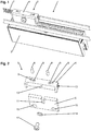
- Fig. 1 shows a power transmission device 1 with a driver 3 for connecting a door leaf with a drive and / or at least one other door leaf.
- the driver 3 has a base body 4 and a connecting plate 5. On the connecting plate 5, the door leaf 11 is fixed, whose upper portion is shown in the drawing.
- the driver 3 is provided with a transmission element 7, which is designed as a toothed belt, by means of locking pins 8, as it is in particular from Fig. 2 can be seen, positively connected.
- the locking pins 8 are inserted in gaps between the teeth of the transmission element 7 from above through holes 9.
- a recess 10 is provided, in which the transmission element 7 is arranged.
- the connecting plate 5 has an elongated recess 11 for receiving a screw 12.
- the screw 12 is screwed into a threaded bore 13 and presses by means of a washer 14, the connecting plate 5 against the base body 4. by the elongated recess 11, the connecting plate 5 can be aligned relative to the base body 4.
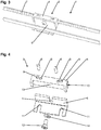
- Fig. 3 shows a power transmission device 1 with a driver 3, which has the base body 4 and a connection angle 6.
- the holes 9 are provided, in which the locking pins 8 can be inserted to positively connect the driver 3 with the transmission element 7 in the manner already described.
- Fig. 4 has the connection angle 6 elongated recesses 11 in order to align the driver 3 accurately.
- the screw 12 is used together with the washer 14 in the manner already described above.
- the base body 4 has at its end faces on projections, between which the connecting plate 5 or the connecting angle 6 can be arranged positively.
- the base body 4 may have a substantially cuboid cross-section, wherein a separate, with the connection plate 5 or the connecting angle 6 can be coupled coupling element to the base body 4 can be fastened. This may be advantageous in terms of simpler manufacture and universal usability of the base body 4.
Landscapes
- Power-Operated Mechanisms For Wings (AREA)
Description
- Die Erfindung betrifft eine Kraftübertragungsvorrichtung für eine Türanlage mit mindestens einem Türflügel, insbesondere für eine Schiebetüranlage.
- Aus dem Stand der Technik ist eine gattungsgemäße Kraftübertragungsvorrichtung für eine Schiebetüranlage bekannt, bei der ein Übertragungselement vorgesehen, an dem ein Mitnehmer zur Ankopplung des Türflügels anordenbar ist. Das Übertragungselement wird zwischen einer Klemmplatte und einem Grundkörper kraftschlüssig eingespannt. Zur Festlegung dieser Verbindung werden Schrauben verwendet, welche die Klemmplatte gegen den Grundkörper drücken. Nachteilig hierbei ist, dass das Übertragungselement, wenn die Schrauben nicht fest genug angezogen sind oder sich beim Betrieb der Türanlage lockern, aus seiner Montageposition zwischen der Klemmplatte und dem Grundkörper herausrutschen kann. Ferner ist diese Montageart sehr aufwändig, da das Übertragungselement aufgrund einer im Grundkörper mittig angeordneten Schraube zerschnitten und beide Enden des Übertragungselements vor dem Aufsetzen der Klemmplatte gleichzeitig gegen den Grundkörper gehalten werden müssen.
- In der
EP 1 927 714 A2 ist eine Kraftübertragungsvorrichtung für eine Türanlage mit zumindest einem Türflügel mit einem Übertragungselement beschrieben, an dem ein einen Grundkörper und einen Verbindungwinkel umfassender Mitnehmer angeordnet ist, wobei der Grundkörper mit einer Aussparung versehen ist, in die das Übertragungselement einlegbar ist, und die Festlegung des Übertragungselements am Grundkörper durch wenigstens eine Schraube erfolgt, die den Grundkörper zumindest abschnittsweise durchgreift und formschlüssig mit dem Übertragungselement zusammenwirkt. Der Übertragungswinkel ist mit dem Türflügel verbindbar. Zudem ist der Verbindungswinkel mit länglichen Ausnehmungen für den Durchtritt der Schrauben sowie mit Bohrungen für Schrauben versehen. Im montierten Zustand ist ein oberer Schenkel des Verbindungswinkels stets auf einem Basisabschnitt des Grundkörpers abgestützt. - Gemäß der
US 2005/0100398 A1 dient ein Befestigungselement der Verbindung eines Übertragungselements mit einem Antriebselement. Das Befestigungselement umfasst einen Koppler mit in Lücken des Übertragungselements eingreifenden Zähnen. Das ein Joch und seitliche Schuhe umfassende Befestigungselement ist mit Fingern versehen, die sich im zusammengesetzten Zustand des Befestigungselements durch die Zähne des Kopplers erstrecken. - In der
US 2008/0060171 A1 ist eine Klemmvorrichtung beschrieben, bei der ein Übertragungselement zwischen einer Klemmplatte und einem Grundkörper kraftschlüssig eingespannt wird, wobei zur Festlegung dieser Verbindung Schrauben verwendet werden, die die Klemmplatte gegen den Grundkörper drücken. - In der
EP 0 543 523 A2 ist ein System zur Betätigung eines Aufzugtürflügels beschrieben, bei dem zur Verbindung des Türflügels mit einem Übertragungselement Koppelelemente vorgesehen sind, die jeweils ein Gehäuse und eine Klemmplatte umfassen. Das Gehäuse ist mit einer Aufnahme versehen, in die zwei Enden des Übertragungselements eingelegt werden, auf die ein zusätzlicher Übertragungselementabschnitt aufgebracht wird, bevor die Klemmplatte mit dem Gehäuse verschraubt wird. Das Gehäuse und die Klemmplatte sind zur Verbindung der beiden Übertragungselementende über durch Schraubbohrungen der Klemmplatte hindurchgeführte Schrauben und im Gehäuse vorgesehene Gewindebohrungen getrennt von der Verbindung mit einer der Anbringung des Türflügels dienenden Klammer miteinander verbindbar. Dabei ist die Klammer bzw. der Verbindungswinkel über ein in diesem vorgesehenes Langloch senkrecht zur Bewegungsrichtung des Übertragungselements gegenüber der das Gehäuse und die Klemmplatte umfassenden Einheit ausrichtbar. - Die Erfindung hat die Aufgabe, die gattungsgemäße Kraftübertragungsvorrichtung dahingehend zu verbessern, dass eine sicherere Halterung des Kraftübertragungselements sowie eine einfachere Montage möglich sind.
- Die Aufgabe wird durch die Merkmale des Patentanspruchs 1 gelöst.
- Die Unteransprüche bilden vorteilhafte Ausgestaltungsmöglichkeiten der Erfindung.
- Der Mitnehmer weist eine Aussparung auf, in welche das Übertragungselement einlegbar ist, wobei die Festlegung des Übertragungselements am Mitnehmer durch mindestens einen Arretierungsstift erfolgt, welcher den Mitnehmer zumindest abschnittsweise durchgreift und formschlüssig mit dem Übertragungselement zusammenwirkt.
- Durch den Formschluss zwischen dem Übertragungselement und dem Arretierungsstift ist eine zuverlässige Festlegung des Übertragungselements gewährleistet. Die Montage ist einfach, da das Übertragungselement im Bereich des Mitnehmers nicht geteilt werden muss und durch das Einlegen in die Aussparung vor dem Montieren des Arretierungsstifts bereits in dieser Position gehalten ist.
- In einer bevorzugten Ausführungsform kann das Übertragungselement ein Zahnriemen sein, wobei mindestens ein Arretierungsstift in eine Zahnlücke des Zahnriemens einbringbar ist. Der in der Zahnlücke angeordnete Arretierungsstift stellt somit den Formschluss zwischen dem Zahnriemen und dem Mitnehmer her.
- Der Mitnehmer weist einen Grundkörper auf, der eine Aussparung zur Aufnahme des Übertragungselements besitzt. Durch die Aussparung wird das Übertragungselement geschützt und gleichzeitig platzsparend am Grundkörper angeordnet.
- Um den mindestens einen Arretierungsstift am Mitnehmer montieren zu können, kann er mindestens eine Bohrung aufweisen.
- An dem Mitnehmer ist mindestens eine Verbindungsplatte und/oder ein Verbindungswinkel angeordnet, um einen Türflügel mit dem Mitnehmer zu verbinden.
- Indem an der Verbindungsplatte und/oder dem Verbindungswinkel mindestens eine Ausnehmung, z.B. ein Langloch und/oder eine Nut vorgesehen ist, kann die Verbindungsplatte und/oder der Verbindungswinkel gegenüber dem Grundkörper und/oder gegenüber dem Türflügel genau ausgerichtet werden.
- Um zu verhindern, dass die Verbindungsplatte und/oder der Verbindungswinkel gegenüber dem Grundkörper parallel zum Übertragungselement verschoben werden kann, ist die Verbindungsplatte und/oder der Verbindungswinkel formschlüssig am Grundkörper montierbar.
- Die Erfindung betrifft ferner eine Türanlage, insbesondere eine Schiebetüranlage, die erfindungsgemäß eine Kraftübertragungsvorrichtung nach einem der Ansprüche 1 bis 3 aufweist.
- Nachfolgend werden zwei Ausführungsbeispiele einer erfindungsgemäßen Kraftübertragungsvorrichtung anhand der beiliegenden Zeichnungen näher erläutert.
- Dabei zeigen:
- Fig. 1
- eine perspektivische Draufsicht auf eine Kraftübertragungsvorrichtung mit einer ersten Ausführungsform eines Mitnehmers;
- Fig. 2
- eine Explosionsansicht des Mitnehmers aus
Fig. 1 ; - Fig. 3
- eine perspektivische Draufsicht auf die Kraftübertragungsvorrichtung mit einer zweiten Ausführungsform des Mitnehmers;
- Fig. 4
- eine Explosionsansicht des Mitnehmers aus
Fig. 3 . -
Fig. 1 zeigt eine Kraftübertragungsvorrichtung 1 mit einem Mitnehmer 3 zum Verbinden eines Türflügels mit einem Antrieb und/oder mindestens einem weiteren Türflügel. - Der Mitnehmer 3 weist einen Grundkörper 4 und eine Verbindungsplatte 5 auf. An der Verbindungsplatte 5 ist der Türflügel 11 befestigt, dessen oberer Bereich in der Zeichnung dargestellt ist.
- Der Mitnehmer 3 ist mit einem Übertragungselement 7, das als ein Zahnriemen ausgebildet ist, mittels Arretierungsstiften 8, wie es insbesondere aus der
Fig. 2 ersichtlich ist, formschlüssig verbunden. Zu diesem Zweck werden die Arretierungsstifte 8 in Lücken zwischen den Zähnen des Übertragungselements 7 von oben durch Bohrungen 9 eingeschoben. - In dem Mitnehmer 3 ist eine Aussparung 10 vorgesehen, in der das Übertragungselement 7 angeordnet ist.
- Die Verbindungsplatte 5 weist eine längliche Ausnehmung 11 zur Aufnahme einer Schraube 12 auf. Die Schraube 12 wird in eine Gewindebohrung 13 eingedreht und presst mittels einer Unterlegscheibe 14 die Verbindungsplatte 5 gegen den Grundkörper 4. durch die längliche Ausnehmung 11 kann die Verbindungsplatte 5 gegenüber dem Grundkörper 4 ausgerichtet werden.
-
Fig. 3 zeigt eine Kraftübertragungsvorrichtung 1 mit einem Mitnehmer 3, der den Grundkörper 4 und einen Verbindungswinkel 6 aufweist. In dem Grundkörper 4 sind die Bohrungen 9 vorgesehen, in welche die Arretierungsstifte 8 eingeschoben werden können, um den Mitnehmer 3 mit dem Übertragungselement 7 in der bereits beschriebenen Weise formschlüssig zu verbinden. - Gemäß
Fig. 4 weist der Verbindungswinkel 6 längliche Ausnehmungen 11 auf, um den Mitnehmer 3 genau ausrichten zu können. Zu diesem Zweck wird die Schraube 12 zusammen mit der Unterlegscheibe 14 in der bereits oben beschriebenen Weise verwendet. - Der Grundkörper 4 weist an seinen Stirnseiten Vorsprünge auf, zwischen denen die Verbindungsplatte 5 oder der Verbindungswinkel 6 formschlüssig angeordnet werden kann.
- In einer alternativen, hier nicht dargestellten Ausführung kann der Grundkörper 4 im wesentlichen quaderförmigen Querschnitt aufweisen, wobei ein separates, mit der Verbindungsplatte 5 oder dem Verbindungswinkel 6 koppelbares Verbindungselement an dem Grundkörper 4 befestigbar ist. Dies kann hinsichtlich der einfacheren Herstellung und universellen Verwendbarkeit des Grundkörpers 4 vorteilhaft sein.
-
- 1
- Kraftübertragungsvorrichtung
- 2
- Türflügel
- 3
- Mitnehmer
- 4
- Grundkörper
- 5
- Verbindungsplatte
- 6
- Verbindungswinkel
- 7
- Übertragungselement
- 8
- Arretierungsstift
- 9
- Bohrung
- 10
- Aussparung
- 11
- Ausnehmung
- 12
- Schraube
- 13
- Gewindebohrung
- 14
- Unterlegscheibe
- 15
- Ausnehmung
- 16
- Ausnehmung
Claims (4)
- Kraftübertragungsvorrichtung (1) für eine Türanlage mit mindestens einem Türflügel (2), insbesondere für eine Schiebetüranlage, mit einem Übertragungselement (7), an dem ein Mitnehmer (3) zur Ankopplung des Türflügels (2) anordenbar ist, wobei der Mitnehmer (3) eine Aussparung (10) aufweist, in welche das Übertragungselement (7) einlegbar ist, die Festlegung des Übertragungselements (7) am Mitnehmer (3) durch mindestens einen Arretierungsstift (8) erfolgt, welcher den Mitnehmer (3) zumindest abschnittsweise durchgreift und formschlüssig mit dem Übertragungselement (7) zusammenwirkt, der Mitnehmer (3) einen die Aussparung (10) zur Aufnahme des Übertragungselements (7) aufweisenden Grundkörper (4) und eine Verbindungsplatte (5) und/oder einen Verbindungswinkel (6) umfasst, die bzw. der an dem Grundkörper (4) angeordnet und mit der bzw. dem der Türflügel (2) verbindbar ist, und an der Verbindungsplatte (5) bzw. dem Verbindungswinkel (6) jeweils mindestens eine längliche Ausnehmung (11) zur Aufnahme einer in eine Gewindebohrung (13) des Grundkörpers (4) eindrehbaren Schraube (12) vorgesehen ist, mittels der die Verbindungsplatte (5) bzw. der Verbindungswinkel (6) unabhängig von der Festlegung des Übertragungselements (7) am Grundkörper (4) senkrecht zur Bewegungsrichtung des Übertragungselements (7) bzw. zur Verschieberichtung des Türflügels (2) in einer zum Türflügel (2) parallelen Ebene gegenüber dem Grundkörper (4) ausrichtbar ist, und wobei der Grundkörper (4) an seinen Stirnseiten Vorsprünge aufweist, zwischen denen die Verbindungsplatte (5) bzw. der Verbindungswinkel (6) formschlüssig angeordnet werden kann, um die Verbindungsplatte (5) bzw. den Verbindungswinkel (6) bezüglich des Grundkörpers (4) in Bewegungsrichtung des Übertragungselements (7) bzw. in Verschieberichtung des Türflügels (2) festzulegen.
- Kraftübertragungsvorrichtung nach Anspruch 1, dadurch gekennzeichnet, dass das Übertragungselement (7) als Zahnriemen ausgebildet ist, wobei der Arretierungsstift (8) in eine Zahnlücke einbringbar ist.
- Kraftübertragungsvorrichtung nach Anspruch 1, dadurch gekennzeichnet, dass in dem Grundkörper (4) mindestens eine Bohrung (9) zur Aufnahme des Arretierungsstifts (8) angeordnet ist.
- Türanlage, insbesondere Schiebetüranlage, dadurch gekennzeichnet, dass sie eine Kraftübertragungsvorrichtung (1) nach einem der Ansprüche 1 bis 3 aufweist.
Applications Claiming Priority (1)
| Application Number | Priority Date | Filing Date | Title |
|---|---|---|---|
| DE102009027324.7A DE102009027324B4 (de) | 2009-06-30 | 2009-06-30 | Kraftübertragungsvorrichtung für eine Türanlage |
Publications (3)
| Publication Number | Publication Date |
|---|---|
| EP2270302A2 EP2270302A2 (de) | 2011-01-05 |
| EP2270302A3 EP2270302A3 (de) | 2013-12-11 |
| EP2270302B1 true EP2270302B1 (de) | 2018-02-28 |
Family
ID=42711676
Family Applications (1)
| Application Number | Title | Priority Date | Filing Date |
|---|---|---|---|
| EP10167441.4A Active EP2270302B1 (de) | 2009-06-30 | 2010-06-28 | Kraftübertragungsvorrichtung für eine Türanlage |
Country Status (2)
| Country | Link |
|---|---|
| EP (1) | EP2270302B1 (de) |
| DE (1) | DE102009027324B4 (de) |
Families Citing this family (4)
| Publication number | Priority date | Publication date | Assignee | Title |
|---|---|---|---|---|
| KR102482948B1 (ko) * | 2013-08-26 | 2022-12-29 | 브룩스 오토메이션 인코퍼레이티드 | 기판 이송 장치 |
| TWI709185B (zh) * | 2013-08-26 | 2020-11-01 | 美商布魯克斯自動機械公司 | 基板搬運裝置 |
| JP6377964B2 (ja) * | 2014-06-06 | 2018-08-22 | ナブテスコ株式会社 | 連結装置及び自動ドア |
| US10920477B2 (en) * | 2018-10-12 | 2021-02-16 | Yasemin Akgor | Sliding door with wireless-controlled motor housed in jamb |
Family Cites Families (6)
| Publication number | Priority date | Publication date | Assignee | Title |
|---|---|---|---|---|
| US5213182A (en) * | 1991-11-19 | 1993-05-25 | Otis Elevator Company | Elevator door operator cog belt linkage |
| DE4414065C1 (de) * | 1994-04-21 | 1996-01-04 | Foerder Weber & Systemtechnik | Zahnriemenverbinder |
| WO1997042108A1 (de) * | 1996-05-08 | 1997-11-13 | Sig Pack Systems Ag | Vorrichtung zum transportieren von produkten |
| US7297082B2 (en) * | 2003-11-10 | 2007-11-20 | Delphi Technologies, Inc. | Flexible drive member attachment |
| US7810219B2 (en) * | 2006-09-08 | 2010-10-12 | Designatronics, Inc. | Clamp for timing belt |
| ES2320951B1 (es) * | 2006-11-28 | 2010-03-04 | Klein Iberica, S.A. | Sistema de accionamiento sincronizado para puertas correderas. |
-
2009
- 2009-06-30 DE DE102009027324.7A patent/DE102009027324B4/de not_active Withdrawn - After Issue
-
2010
- 2010-06-28 EP EP10167441.4A patent/EP2270302B1/de active Active
Non-Patent Citations (1)
| Title |
|---|
| None * |
Also Published As
| Publication number | Publication date |
|---|---|
| DE102009027324A1 (de) | 2011-01-05 |
| DE102009027324B4 (de) | 2016-12-01 |
| EP2270302A3 (de) | 2013-12-11 |
| EP2270302A2 (de) | 2011-01-05 |
Similar Documents
| Publication | Publication Date | Title |
|---|---|---|
| EP3472403B1 (de) | Vorrichtung zum befestigen eines plattenförmigen bauteils in einer aufnahmenut einer tragschiene | |
| EP2270302B1 (de) | Kraftübertragungsvorrichtung für eine Türanlage | |
| DE7705465U1 (de) | Grundplatte fuer verdeckt angeordnete scharniere, insbesondere moebelscharniere | |
| EP2084356B1 (de) | Bandanordnung für türen, fenster oder dergleichen | |
| DE10101318B4 (de) | Vorrichtung zum verspannenden Verbinden von zueinander beabstandeten Bauteilen | |
| DE102022122108B3 (de) | Positioniervorrichtung mit Stellglied und Gegenanschlag aus Keilelementen | |
| DE202008016071U1 (de) | Band zur scharniergelenkigen Verbindung eines Flügels an einem Rahmen | |
| DE202007005304U1 (de) | Verbindungsanordnung für Profilschienen | |
| EP0143774B1 (de) | Bandhalterung für Türbänder | |
| EP2514892B1 (de) | System zur Befestigung eines Beschlagteils | |
| EP2161401A2 (de) | Anordnung zur Verbindung eines Zugmittels mit einem Mitnehmerelement | |
| EP2385200B1 (de) | Beschlagteil zur Befestigung an einer C-förmigen Beschlagteilnut | |
| DE3151224A1 (de) | Vorrichtung zur befestigung eines getriebes an einem rahmen von fenstern, tueren oder dergleichen | |
| DE102007008963B3 (de) | Aufnahmeelement an Block- oder Futterzargen für einen Bandlappen eines Tür- oder Fensterbandes | |
| EP1662627A1 (de) | Klemmvorrichtung zur lösbaren Befestigung eines Gerätegehäuses an einer Profilschiene | |
| DE102010039605B4 (de) | Geschlitzte Zahnstange zur Reduzierung der Federrate | |
| DE202010000291U1 (de) | Bandlappenanordnung | |
| EP2617927A2 (de) | Gleitschienenanordnung | |
| EP1676761A1 (de) | Scheibenwischvorrichtung | |
| EP1508704B1 (de) | Profilverbindung | |
| EP2050900A2 (de) | Aufnahmestift zum Aufnehmen von Türgriffen, Tür mit Türgriffen, Anordnung aus einem Aufnahmestift und aus einer Schlossnuss sowie Verfahren zum Befestigen von Türgriffen | |
| EP3295913B1 (de) | Patientenlagerungsplatte mit zubehörteil | |
| DE102014225155B4 (de) | Antriebsanordnung zum Verstellen einer Komponente in einem Kraftfahrzeug | |
| DE102013106829B3 (de) | Bandaufnahmeelement für Türbänder | |
| EP1028488A1 (de) | Anschlussklemme für ein elektrisches Installationsgerät |
Legal Events
| Date | Code | Title | Description |
|---|---|---|---|
| PUAI | Public reference made under article 153(3) epc to a published international application that has entered the european phase |
Free format text: ORIGINAL CODE: 0009012 |
|
| AK | Designated contracting states |
Kind code of ref document: A2 Designated state(s): AL AT BE BG CH CY CZ DE DK EE ES FI FR GB GR HR HU IE IS IT LI LT LU LV MC MK MT NL NO PL PT RO SE SI SK SM TR |
|
| AX | Request for extension of the european patent |
Extension state: BA ME RS |
|
| PUAL | Search report despatched |
Free format text: ORIGINAL CODE: 0009013 |
|
| AK | Designated contracting states |
Kind code of ref document: A3 Designated state(s): AL AT BE BG CH CY CZ DE DK EE ES FI FR GB GR HR HU IE IS IT LI LT LU LV MC MK MT NL NO PL PT RO SE SI SK SM TR |
|
| AX | Request for extension of the european patent |
Extension state: BA ME RS |
|
| RIC1 | Information provided on ipc code assigned before grant |
Ipc: E05F 15/14 20060101AFI20131106BHEP |
|
| 17P | Request for examination filed |
Effective date: 20140611 |
|
| RBV | Designated contracting states (corrected) |
Designated state(s): AL AT BE BG CH CY CZ DE DK EE ES FI FR GB GR HR HU IE IS IT LI LT LU LV MC MK MT NL NO PL PT RO SE SI SK SM TR |
|
| 17Q | First examination report despatched |
Effective date: 20160713 |
|
| APBK | Appeal reference recorded |
Free format text: ORIGINAL CODE: EPIDOSNREFNE |
|
| APBN | Date of receipt of notice of appeal recorded |
Free format text: ORIGINAL CODE: EPIDOSNNOA2E |
|
| APBR | Date of receipt of statement of grounds of appeal recorded |
Free format text: ORIGINAL CODE: EPIDOSNNOA3E |
|
| REG | Reference to a national code |
Ref country code: DE Ref legal event code: R079 Ref document number: 502010014699 Country of ref document: DE Free format text: PREVIOUS MAIN CLASS: E05F0015140000 Ipc: E05F0015643000 |
|
| APBV | Interlocutory revision of appeal recorded |
Free format text: ORIGINAL CODE: EPIDOSNIRAPE |
|
| GRAP | Despatch of communication of intention to grant a patent |
Free format text: ORIGINAL CODE: EPIDOSNIGR1 |
|
| RIC1 | Information provided on ipc code assigned before grant |
Ipc: E05F 15/643 20150101AFI20170825BHEP |
|
| INTG | Intention to grant announced |
Effective date: 20170929 |
|
| GRAS | Grant fee paid |
Free format text: ORIGINAL CODE: EPIDOSNIGR3 |
|
| GRAA | (expected) grant |
Free format text: ORIGINAL CODE: 0009210 |
|
| AK | Designated contracting states |
Kind code of ref document: B1 Designated state(s): AL AT BE BG CH CY CZ DE DK EE ES FI FR GB GR HR HU IE IS IT LI LT LU LV MC MK MT NL NO PL PT RO SE SI SK SM TR |
|
| REG | Reference to a national code |
Ref country code: GB Ref legal event code: FG4D Free format text: NOT ENGLISH Ref country code: CH Ref legal event code: EP |
|
| REG | Reference to a national code |
Ref country code: AT Ref legal event code: REF Ref document number: 974333 Country of ref document: AT Kind code of ref document: T Effective date: 20180315 |
|
| REG | Reference to a national code |
Ref country code: IE Ref legal event code: FG4D Free format text: LANGUAGE OF EP DOCUMENT: GERMAN |
|
| REG | Reference to a national code |
Ref country code: DE Ref legal event code: R096 Ref document number: 502010014699 Country of ref document: DE |
|
| REG | Reference to a national code |
Ref country code: NL Ref legal event code: MP Effective date: 20180228 |
|
| REG | Reference to a national code |
Ref country code: LT Ref legal event code: MG4D |
|
| PG25 | Lapsed in a contracting state [announced via postgrant information from national office to epo] |
Ref country code: ES Free format text: LAPSE BECAUSE OF FAILURE TO SUBMIT A TRANSLATION OF THE DESCRIPTION OR TO PAY THE FEE WITHIN THE PRESCRIBED TIME-LIMIT Effective date: 20180228 Ref country code: NL Free format text: LAPSE BECAUSE OF FAILURE TO SUBMIT A TRANSLATION OF THE DESCRIPTION OR TO PAY THE FEE WITHIN THE PRESCRIBED TIME-LIMIT Effective date: 20180228 Ref country code: CY Free format text: LAPSE BECAUSE OF FAILURE TO SUBMIT A TRANSLATION OF THE DESCRIPTION OR TO PAY THE FEE WITHIN THE PRESCRIBED TIME-LIMIT Effective date: 20180228 Ref country code: LT Free format text: LAPSE BECAUSE OF FAILURE TO SUBMIT A TRANSLATION OF THE DESCRIPTION OR TO PAY THE FEE WITHIN THE PRESCRIBED TIME-LIMIT Effective date: 20180228 Ref country code: HR Free format text: LAPSE BECAUSE OF FAILURE TO SUBMIT A TRANSLATION OF THE DESCRIPTION OR TO PAY THE FEE WITHIN THE PRESCRIBED TIME-LIMIT Effective date: 20180228 Ref country code: NO Free format text: LAPSE BECAUSE OF FAILURE TO SUBMIT A TRANSLATION OF THE DESCRIPTION OR TO PAY THE FEE WITHIN THE PRESCRIBED TIME-LIMIT Effective date: 20180528 Ref country code: FI Free format text: LAPSE BECAUSE OF FAILURE TO SUBMIT A TRANSLATION OF THE DESCRIPTION OR TO PAY THE FEE WITHIN THE PRESCRIBED TIME-LIMIT Effective date: 20180228 |
|
| PG25 | Lapsed in a contracting state [announced via postgrant information from national office to epo] |
Ref country code: GR Free format text: LAPSE BECAUSE OF FAILURE TO SUBMIT A TRANSLATION OF THE DESCRIPTION OR TO PAY THE FEE WITHIN THE PRESCRIBED TIME-LIMIT Effective date: 20180529 Ref country code: BG Free format text: LAPSE BECAUSE OF FAILURE TO SUBMIT A TRANSLATION OF THE DESCRIPTION OR TO PAY THE FEE WITHIN THE PRESCRIBED TIME-LIMIT Effective date: 20180528 Ref country code: LV Free format text: LAPSE BECAUSE OF FAILURE TO SUBMIT A TRANSLATION OF THE DESCRIPTION OR TO PAY THE FEE WITHIN THE PRESCRIBED TIME-LIMIT Effective date: 20180228 Ref country code: SE Free format text: LAPSE BECAUSE OF FAILURE TO SUBMIT A TRANSLATION OF THE DESCRIPTION OR TO PAY THE FEE WITHIN THE PRESCRIBED TIME-LIMIT Effective date: 20180228 |
|
| PG25 | Lapsed in a contracting state [announced via postgrant information from national office to epo] |
Ref country code: MT Free format text: LAPSE BECAUSE OF FAILURE TO SUBMIT A TRANSLATION OF THE DESCRIPTION OR TO PAY THE FEE WITHIN THE PRESCRIBED TIME-LIMIT Effective date: 20180228 |
|
| PG25 | Lapsed in a contracting state [announced via postgrant information from national office to epo] |
Ref country code: RO Free format text: LAPSE BECAUSE OF FAILURE TO SUBMIT A TRANSLATION OF THE DESCRIPTION OR TO PAY THE FEE WITHIN THE PRESCRIBED TIME-LIMIT Effective date: 20180228 Ref country code: PL Free format text: LAPSE BECAUSE OF FAILURE TO SUBMIT A TRANSLATION OF THE DESCRIPTION OR TO PAY THE FEE WITHIN THE PRESCRIBED TIME-LIMIT Effective date: 20180228 Ref country code: AL Free format text: LAPSE BECAUSE OF FAILURE TO SUBMIT A TRANSLATION OF THE DESCRIPTION OR TO PAY THE FEE WITHIN THE PRESCRIBED TIME-LIMIT Effective date: 20180228 Ref country code: IT Free format text: LAPSE BECAUSE OF FAILURE TO SUBMIT A TRANSLATION OF THE DESCRIPTION OR TO PAY THE FEE WITHIN THE PRESCRIBED TIME-LIMIT Effective date: 20180228 Ref country code: EE Free format text: LAPSE BECAUSE OF FAILURE TO SUBMIT A TRANSLATION OF THE DESCRIPTION OR TO PAY THE FEE WITHIN THE PRESCRIBED TIME-LIMIT Effective date: 20180228 |
|
| REG | Reference to a national code |
Ref country code: DE Ref legal event code: R097 Ref document number: 502010014699 Country of ref document: DE |
|
| PG25 | Lapsed in a contracting state [announced via postgrant information from national office to epo] |
Ref country code: DK Free format text: LAPSE BECAUSE OF FAILURE TO SUBMIT A TRANSLATION OF THE DESCRIPTION OR TO PAY THE FEE WITHIN THE PRESCRIBED TIME-LIMIT Effective date: 20180228 Ref country code: SM Free format text: LAPSE BECAUSE OF FAILURE TO SUBMIT A TRANSLATION OF THE DESCRIPTION OR TO PAY THE FEE WITHIN THE PRESCRIBED TIME-LIMIT Effective date: 20180228 Ref country code: SK Free format text: LAPSE BECAUSE OF FAILURE TO SUBMIT A TRANSLATION OF THE DESCRIPTION OR TO PAY THE FEE WITHIN THE PRESCRIBED TIME-LIMIT Effective date: 20180228 Ref country code: CZ Free format text: LAPSE BECAUSE OF FAILURE TO SUBMIT A TRANSLATION OF THE DESCRIPTION OR TO PAY THE FEE WITHIN THE PRESCRIBED TIME-LIMIT Effective date: 20180228 |
|
| REG | Reference to a national code |
Ref country code: CH Ref legal event code: PK Free format text: BERICHTIGUNGEN |
|
| RIC2 | Information provided on ipc code assigned after grant |
Ipc: E05F 15/643 20150101AFI20170825BHEP |
|
| PLBE | No opposition filed within time limit |
Free format text: ORIGINAL CODE: 0009261 |
|
| STAA | Information on the status of an ep patent application or granted ep patent |
Free format text: STATUS: NO OPPOSITION FILED WITHIN TIME LIMIT |
|
| REG | Reference to a national code |
Ref country code: CH Ref legal event code: PK Free format text: BERICHTIGUNGEN Ref country code: CH Ref legal event code: PL |
|
| 26N | No opposition filed |
Effective date: 20181129 |
|
| RIC2 | Information provided on ipc code assigned after grant |
Ipc: E05F 15/643 20150101AFI20170825BHEP |
|
| GBPC | Gb: european patent ceased through non-payment of renewal fee |
Effective date: 20180628 |
|
| PG25 | Lapsed in a contracting state [announced via postgrant information from national office to epo] |
Ref country code: SI Free format text: LAPSE BECAUSE OF FAILURE TO SUBMIT A TRANSLATION OF THE DESCRIPTION OR TO PAY THE FEE WITHIN THE PRESCRIBED TIME-LIMIT Effective date: 20180228 |
|
| REG | Reference to a national code |
Ref country code: BE Ref legal event code: MM Effective date: 20180630 |
|
| PG25 | Lapsed in a contracting state [announced via postgrant information from national office to epo] |
Ref country code: LU Free format text: LAPSE BECAUSE OF NON-PAYMENT OF DUE FEES Effective date: 20180628 Ref country code: MC Free format text: LAPSE BECAUSE OF FAILURE TO SUBMIT A TRANSLATION OF THE DESCRIPTION OR TO PAY THE FEE WITHIN THE PRESCRIBED TIME-LIMIT Effective date: 20180228 |
|
| REG | Reference to a national code |
Ref country code: IE Ref legal event code: MM4A |
|
| PG25 | Lapsed in a contracting state [announced via postgrant information from national office to epo] |
Ref country code: CH Free format text: LAPSE BECAUSE OF NON-PAYMENT OF DUE FEES Effective date: 20180630 Ref country code: IE Free format text: LAPSE BECAUSE OF NON-PAYMENT OF DUE FEES Effective date: 20180628 Ref country code: GB Free format text: LAPSE BECAUSE OF NON-PAYMENT OF DUE FEES Effective date: 20180628 Ref country code: FR Free format text: LAPSE BECAUSE OF NON-PAYMENT OF DUE FEES Effective date: 20180630 Ref country code: LI Free format text: LAPSE BECAUSE OF NON-PAYMENT OF DUE FEES Effective date: 20180630 |
|
| PG25 | Lapsed in a contracting state [announced via postgrant information from national office to epo] |
Ref country code: BE Free format text: LAPSE BECAUSE OF NON-PAYMENT OF DUE FEES Effective date: 20180630 |
|
| REG | Reference to a national code |
Ref country code: AT Ref legal event code: MM01 Ref document number: 974333 Country of ref document: AT Kind code of ref document: T Effective date: 20180628 |
|
| PG25 | Lapsed in a contracting state [announced via postgrant information from national office to epo] |
Ref country code: AT Free format text: LAPSE BECAUSE OF NON-PAYMENT OF DUE FEES Effective date: 20180628 |
|
| PG25 | Lapsed in a contracting state [announced via postgrant information from national office to epo] |
Ref country code: TR Free format text: LAPSE BECAUSE OF FAILURE TO SUBMIT A TRANSLATION OF THE DESCRIPTION OR TO PAY THE FEE WITHIN THE PRESCRIBED TIME-LIMIT Effective date: 20180228 |
|
| PG25 | Lapsed in a contracting state [announced via postgrant information from national office to epo] |
Ref country code: PT Free format text: LAPSE BECAUSE OF FAILURE TO SUBMIT A TRANSLATION OF THE DESCRIPTION OR TO PAY THE FEE WITHIN THE PRESCRIBED TIME-LIMIT Effective date: 20180228 Ref country code: HU Free format text: LAPSE BECAUSE OF FAILURE TO SUBMIT A TRANSLATION OF THE DESCRIPTION OR TO PAY THE FEE WITHIN THE PRESCRIBED TIME-LIMIT; INVALID AB INITIO Effective date: 20100628 |
|
| PG25 | Lapsed in a contracting state [announced via postgrant information from national office to epo] |
Ref country code: MK Free format text: LAPSE BECAUSE OF NON-PAYMENT OF DUE FEES Effective date: 20180228 |
|
| PG25 | Lapsed in a contracting state [announced via postgrant information from national office to epo] |
Ref country code: IS Free format text: LAPSE BECAUSE OF FAILURE TO SUBMIT A TRANSLATION OF THE DESCRIPTION OR TO PAY THE FEE WITHIN THE PRESCRIBED TIME-LIMIT Effective date: 20180628 |
|
| P01 | Opt-out of the competence of the unified patent court (upc) registered |
Effective date: 20230510 |
|
| PGFP | Annual fee paid to national office [announced via postgrant information from national office to epo] |
Ref country code: DE Payment date: 20250630 Year of fee payment: 16 |