EP2269737B1 - Dispositif d'analyse comprenant des zones de réaction en série - Google Patents
Dispositif d'analyse comprenant des zones de réaction en série Download PDFInfo
- Publication number
- EP2269737B1 EP2269737B1 EP10166665.9A EP10166665A EP2269737B1 EP 2269737 B1 EP2269737 B1 EP 2269737B1 EP 10166665 A EP10166665 A EP 10166665A EP 2269737 B1 EP2269737 B1 EP 2269737B1
- Authority
- EP
- European Patent Office
- Prior art keywords
- zone
- reaction
- reaction zone
- analysis device
- flow path
- Prior art date
- Legal status (The legal status is an assumption and is not a legal conclusion. Google has not performed a legal analysis and makes no representation as to the accuracy of the status listed.)
- Active
Links
Images

Classifications
-
- B—PERFORMING OPERATIONS; TRANSPORTING
- B01—PHYSICAL OR CHEMICAL PROCESSES OR APPARATUS IN GENERAL
- B01L—CHEMICAL OR PHYSICAL LABORATORY APPARATUS FOR GENERAL USE
- B01L3/00—Containers or dishes for laboratory use, e.g. laboratory glassware; Droppers
- B01L3/50—Containers for the purpose of retaining a material to be analysed, e.g. test tubes
- B01L3/502—Containers for the purpose of retaining a material to be analysed, e.g. test tubes with fluid transport, e.g. in multi-compartment structures
- B01L3/5027—Containers for the purpose of retaining a material to be analysed, e.g. test tubes with fluid transport, e.g. in multi-compartment structures by integrated microfluidic structures, i.e. dimensions of channels and chambers are such that surface tension forces are important, e.g. lab-on-a-chip
-
- B—PERFORMING OPERATIONS; TRANSPORTING
- B01—PHYSICAL OR CHEMICAL PROCESSES OR APPARATUS IN GENERAL
- B01L—CHEMICAL OR PHYSICAL LABORATORY APPARATUS FOR GENERAL USE
- B01L2200/00—Solutions for specific problems relating to chemical or physical laboratory apparatus
- B01L2200/16—Reagents, handling or storing thereof
-
- B—PERFORMING OPERATIONS; TRANSPORTING
- B01—PHYSICAL OR CHEMICAL PROCESSES OR APPARATUS IN GENERAL
- B01L—CHEMICAL OR PHYSICAL LABORATORY APPARATUS FOR GENERAL USE
- B01L2300/00—Additional constructional details
- B01L2300/06—Auxiliary integrated devices, integrated components
- B01L2300/0681—Filter
-
- B—PERFORMING OPERATIONS; TRANSPORTING
- B01—PHYSICAL OR CHEMICAL PROCESSES OR APPARATUS IN GENERAL
- B01L—CHEMICAL OR PHYSICAL LABORATORY APPARATUS FOR GENERAL USE
- B01L2300/00—Additional constructional details
- B01L2300/08—Geometry, shape and general structure
- B01L2300/0809—Geometry, shape and general structure rectangular shaped
- B01L2300/0816—Cards, e.g. flat sample carriers usually with flow in two horizontal directions
-
- B—PERFORMING OPERATIONS; TRANSPORTING
- B01—PHYSICAL OR CHEMICAL PROCESSES OR APPARATUS IN GENERAL
- B01L—CHEMICAL OR PHYSICAL LABORATORY APPARATUS FOR GENERAL USE
- B01L2300/00—Additional constructional details
- B01L2300/08—Geometry, shape and general structure
- B01L2300/0861—Configuration of multiple channels and/or chambers in a single devices
- B01L2300/0864—Configuration of multiple channels and/or chambers in a single devices comprising only one inlet and multiple receiving wells, e.g. for separation, splitting
-
- B—PERFORMING OPERATIONS; TRANSPORTING
- B01—PHYSICAL OR CHEMICAL PROCESSES OR APPARATUS IN GENERAL
- B01L—CHEMICAL OR PHYSICAL LABORATORY APPARATUS FOR GENERAL USE
- B01L2300/00—Additional constructional details
- B01L2300/12—Specific details about materials
- B01L2300/126—Paper
-
- B—PERFORMING OPERATIONS; TRANSPORTING
- B01—PHYSICAL OR CHEMICAL PROCESSES OR APPARATUS IN GENERAL
- B01L—CHEMICAL OR PHYSICAL LABORATORY APPARATUS FOR GENERAL USE
- B01L2400/00—Moving or stopping fluids
- B01L2400/04—Moving fluids with specific forces or mechanical means
- B01L2400/0403—Moving fluids with specific forces or mechanical means specific forces
- B01L2400/0406—Moving fluids with specific forces or mechanical means specific forces capillary forces
-
- B—PERFORMING OPERATIONS; TRANSPORTING
- B01—PHYSICAL OR CHEMICAL PROCESSES OR APPARATUS IN GENERAL
- B01L—CHEMICAL OR PHYSICAL LABORATORY APPARATUS FOR GENERAL USE
- B01L2400/00—Moving or stopping fluids
- B01L2400/04—Moving fluids with specific forces or mechanical means
- B01L2400/0403—Moving fluids with specific forces or mechanical means specific forces
- B01L2400/0409—Moving fluids with specific forces or mechanical means specific forces centrifugal forces
-
- B—PERFORMING OPERATIONS; TRANSPORTING
- B01—PHYSICAL OR CHEMICAL PROCESSES OR APPARATUS IN GENERAL
- B01L—CHEMICAL OR PHYSICAL LABORATORY APPARATUS FOR GENERAL USE
- B01L2400/00—Moving or stopping fluids
- B01L2400/04—Moving fluids with specific forces or mechanical means
- B01L2400/0403—Moving fluids with specific forces or mechanical means specific forces
- B01L2400/0415—Moving fluids with specific forces or mechanical means specific forces electrical forces, e.g. electrokinetic
- B01L2400/0418—Moving fluids with specific forces or mechanical means specific forces electrical forces, e.g. electrokinetic electro-osmotic flow [EOF]
-
- B—PERFORMING OPERATIONS; TRANSPORTING
- B01—PHYSICAL OR CHEMICAL PROCESSES OR APPARATUS IN GENERAL
- B01L—CHEMICAL OR PHYSICAL LABORATORY APPARATUS FOR GENERAL USE
- B01L2400/00—Moving or stopping fluids
- B01L2400/04—Moving fluids with specific forces or mechanical means
- B01L2400/0475—Moving fluids with specific forces or mechanical means specific mechanical means and fluid pressure
Definitions
- the present invention relates to an improved lateral flow device and a method involving the device.
- the uncertainty of a result is an important measure of the quality of the result.
- the terms "uncertainty of a result” and “uncertainty of a measurement” comprise an evaluation of the precision of the method leading to the result or measurement. All parts of the method or measurement, which possibly influence the quality, need to be considered. In the instance of a clinical analysis or assay is concerned, information about the uncertainty of the results should preferably be available.
- GUM Guide to the Expression of Uncertainty in Measurement, International Organisation of Standardisation, ISO, Genève, 1995
- PCT/SE03/00919 relates to a micro fluidic system comprising a substrate and provided on said substrate there is at least one flow path comprising a plurality of micro posts protruding upwards from said substrate, the spacing between the micro posts being small enough to induce a capillary action in a liquid sample applied, so as to force said liquid to move.
- the device can comprise a denser zone which can act as a sieve preventing for instance cells to pass.
- microstructures where the shape, size and/or center-to-center distance forms a variations in, for instance, the deposition of reagents on the assay device, binding of reagents to the assay device, drying of the reagents on the assay device, and reading of a signal from the assay device.
- WO 2008/137008 to Claros Diagnostics Inc. discloses a device which has a reagent arranged in a microfluidic channel of a microfluidic system of a substrate.
- a fluidic connector includes a fluid path with a fluid path inlet and a fluid path outlet connected to an outlet and an inlet of microfluidic channels to allow fluid communication between the path and the channels, respectively.
- the path contains a sample or the reagent arranged prior to connection of the connector to the substrate.
- the reaction area comprises at least two meandering channel regions connected in series. It is disclosed that detection zones can be connected in series. It is disclosed that the detected signal can be different at different portions of a region.
- a problem in WO 2008/137008 is that this device is still susceptible to variations in factors such as deposition of reagents on the assay device, binding of reagents to the assay device, drying of the reagents on the assay device, and reading of a signal from the assay device.
- US 2008273918 discloses fluidic connectors, methods, and devices for performing analyses (e.g., immunoassays) in microfluidic systems.
- WO 01/02093 discloses a detection article including at least one fluid control film layer having at least one microstructured major surface with a plurality of microchannels therein.
- US 2008/003572 discloses a capillary system for controlling the flow of fluid, comprising: at least one loading site, at least one flow channel having one or more test sites, and at least one capillary pump controlling the flow rate of fluid in the flow channel, characterized in that said capillary pump has at least two different zones with different capillary pressures.
- an analysis device comprising a substrate having at least one sample addition zone, at least one sink, and at least one flow path connecting the at least one sample addition zone and the at least one sink, wherein the at least one flow path comprises projections substantially vertical to the surface of said substrate and having a height (H), diameter (D) and reciprocal spacing (t1, t2) such that lateral capillary flow of a liquid sample is achieved, wherein the device comprises at least two reaction zones in series, wherein each reaction zone is adapted to facilitating measurement of a response originating from one and the same analyte, and wherein the at least two reaction zones are positioned to allow calculation of the concentration of at least one analyte.
- a system comprising an analysis device as described above and a reader adapted to read a response from each of the at least two reaction zones in series, wherein the reader comprises a responses are read in at least two reaction zones in series.
- the at least two values are used in the calculation of the end result including an estimate of the uncertainty.
- Advantages include that there is provided further possibilities to control the signals that can be read from the different reaction zones. Additionally a more accurate value can be calculated. Variations may originate from variables such as but not limited to deposition, binding, drying and reading. Effects of such variations are reduced by this invention. The invention allows the estimation of the uncertainty in the result.
- microprocessor adapted to calculate a concentration based on the measured responses.
- a lateral flow assay device with several reaction zones in series where responses are read. Similar, but not necessarily identical responses, are read in the several reaction zones, and thus for instance a concentration of an analyte and an estimate of the uncertainty may be calculated based upon the measured responses. Most often the measured values in the reactions zones in series are not identical depending of factors including but not limited to sample concentration, types of assay, amount of sample, distance between the serial reaction zones.
- Features include that several responses are read in at least two reaction zones in series. The at least two values are used in the calculation of the end result including an estimate of the uncertainty.
- Advantages include that there is provided further possibilities to control the signals that can be read from the different reaction zones. Additionally a more accurate value can be calculated. Variations may originate from variables such as but not limited to deposition, binding, drying and reading. Effects of such variations are reduced by this invention. The invention allows the estimation of the uncertainty in the result.
- analysis means the process in which at least one analyte is determined.
- analysis device means a device which is used to analyse a sample.
- a diagnostic device is a non limiting example of an analysis device.
- analyte means a substance or chemical or biological constituent of which one or more properties are determined in an analytical procedure.
- An analyte or a component itself can often not be measured, but a measurable property of the analyte can. For instance, it is possible to measure the concentration of an analyte.
- capillary flow means flow induced mainly by capillary force.
- flow path means an area on the device where flow of liquid can occur between different zones.
- the term "open" used in connection with capillary flow means that the system is open i.e. the system is without at lid entirely, or if there is a lid or partial lid, the lid is not in capillary contact with the sample liquid, i.e. a lid shall not take part in creating the capillary force.
- reaction zone means an area on an analysis device where molecules in a sample can be detected.
- response means a measurable phenomenon originating from a reaction zone on the analysis device.
- the response includes but is not limited to light emitted from fluorescent molecules.
- sample addition zone means a zone where a sample is added.
- the term "sink” means an area with the capacity of receiving liquid sample.
- an analysis device comprising a substrate having at least one sample addition zone, at least one sink, and at least one flow path connecting the at least one sample addition zone and the at least one sink, wherein the at least one flow path comprises projections substantially vertical to the surface of said substrate and having a height (H), diameter (D) and reciprocal spacing (t1, t2) such that lateral capillary flow of a liquid sample is achieved, wherein the device comprises at least two reaction zones in series, wherein each reaction zone is adapted to facilitating measurement of a response originating from one and the same analyte, and wherein the at least two reaction zones are positioned to allow calculation of the concentration of at least one analyte.
- the exact position of the at least two reaction zones can vary, different positions are conceived as long as the concentration of at least one analyte can be calculated.
- the fact that the at least two reaction zones are positioned to allow calculation of the concentration of at least one analyte means that the at least two reaction zones either are positioned in places where the measured responses from one and the same analyte are approximately the same within the uncertainty of the measurement, or that they are positioned so that the measured responses from one and the same analyte are different but in a predictable manner, so that the concentration can be calculated.
- One example of the latter case is two reaction zones placed in series with a short distance therebetween.
- the first may give rise to one measured response and the second may give rise to a lower measured response, depending on factors such as the distance between the at least two reaction zones and the assay which is used. Experiments may for instance conclude that the measured response in the second zone always is a certain fraction of the measured response in the first zone.
- the at least two reaction zones are positioned so that the measured responses from one and the same analyte are the same within the uncertainty of the measurement.
- the reaction zone closest to the sample addition zone has an area which is different than the area of any one of the other reaction zone(s). In one embodiment the reaction zone closest to the sample addition zone has an area which is smaller than the area of any one of the other reaction zone(s). In one embodiment the reaction zone closest to the sample addition zone has the smallest area, and the reaction furthest from the sample addition zone has the largest area. In one embodiment the analysis device comprises three reaction zones where the reaction zone closest to the sample addition zone has the smallest area, the reaction furthest from the sample addition zone has the largest area, and the intermediate reaction zone has the second smallest area. The possibility to adjust the area of the reaction zone provides a possibility to control the amount and fraction in the sample that binds to reagent in the reaction zone.
- reaction zone closest to the sample addition zone it is possible to let a certain suitable fraction of sample bind to the reaction zone closest to the sample addition zone. If the reaction zone closest to the sample addition zone is not made too large a useful amount of sample will be left in the sample fluid and will flow to the remaining reaction zones. Thus it is possible to vary the areas of the at least two reaction zones in order to obtain suitable signal responses from all reaction zones for a sample.
- the at least two reaction zones have different geometries.
- the reaction zone closest to the sample addition zone has a width which is smaller than the width of any one of the other reaction zone(s).
- the reaction zone closest to the sample addition zone has longitudinal shape as seen in the direction of the flow.
- the reaction zone furthest from the sample addition zone extends over the entire width of the flow path.
- there are three reaction zones where the reaction zone closest to the sample addition zone has longitudinal shape as seen in the direction of the flow with a small width, the intermediate reaction zone has a cross section which is a part of the width of the flow path, and the reaction zone furthest from the sample addition zone extends over the entire width of the flow path.
- the reaction zone closest to the sample addition zone has width corresponding to 10-25% of the width of the flow path
- the intermediate reaction zone has a width corresponding to 25-75% of the flow path
- the reaction zone furthest from the sample addition zone extends over the entire width of the flow path.
- each reaction zone comprises at least one reagent and the concentrations of reagent in the at least two reaction zones are different.
- the reaction zone closest to the sample addition zone has a concentration of reagent which is lower than the concentration of reagent in any one of the other reaction zone(s).
- there are three reaction zones the reaction zone closest to the sample addition zone has the lowest concentration of reagent, the intermediate reaction zone has an intermediate concentration of reagent and the reaction zone furthest from the sample addition zone has the highest concentration of reagent. In this way there is provided yet another possibility to control the signals from the different reaction zones.
- serial reaction zones are positioned in one (single) flow path.
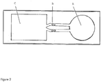
- the analysis device comprises at least two flow paths connecting the at least one sample addition zone and the at least one sink, and wherein each flow path comprises at least two reaction zones. This latter embodiment provides a possibility to reduce the effects of variations in flow between different flow paths. An example of such an embodiment is depicted in figure 2 .
- the at least one flow path is at least partially open.
- a system comprising an analysis device as described above and a reader adapted to read a response from each of the at least two reaction zones in series, wherein the reader comprises a microprocessor adapted to calculate a concentration based on the measured responses.
- microprocessor calculate values including but not limited to a concentration of an analyte, a calculated response value, a sum, and an estimate of the uncertainty based on the measured responses using known algorithms and based on experiments in order to weight the measured responses from the at least two reaction zones in series.
- the reader of the system comprises a fluorescence reader.
- the responses measured in the at least two reaction zones are different. This situation is the most likely.
- the at least two reaction zones are positioned in series the measured responses are typically different.
- the calculation of a value from the responses can thus not in general follow an established scheme for the calculation of a mean value. Experiments may have to be performed in order to ascertain that the measured at least two values are correctly weighted in relation to each other.
- the responses which are measured from the analysis device are used for calculating various values including but not limited to the concentration of an analyte and an estimate of the uncertainty.
- a calculated concentration and an estimate of the associated uncertainty are calculated based on the measured responses and based on calibration experiments.
- a sum and an estimate of the associated uncertainty are calculated based on the measured responses.
- the measured responses are used to calculate a concentration of an analyte. Often this is accomplished with a standard curve.
- a person skilled in the art can in the light of this description obtain a standard curve by measuring samples with known concentrations of an analyte. The skilled person can then use such a standard curve to calculate the concentration from the measured responses. Also the fact that the at least two reaction zones in series may give different results may have to be considered by performing experiments.
- the invention allows an estimate of the uncertainty to be calculated.
- concentration of at least one analyte and an estimate of the associated uncertainty of the concentration are calculated based on the measured responses.
- Plastic substrate chips made of Zeonor (Zeon, Japan) having oxidized dextran on the surface for covalently immobilization of proteins via Shiffs base coupling were used.
- Three reaction zones in the flow channel were deposited (Biodot AD3200) with 60 nl of 1 mg/ml anti-CRP mAb (Fitzgerald Ind. US, M701289).
- a device as schematically depicted in fig 1 was used. After 15 min the chips were dried at 20% humidity and 30°C.
- a model system with fluorophore-labelled CRP was used.
- CRP was fluorescently labelled according to the supplier's instructions using Alexa Fluor® 647 Protein Labelling Kit (Invitrogen, US). Labelled CRP was added to CRP depleted serum (Scipack, UK) resulting in a final concentration of 80 ng/ml.
Claims (14)
- Dispositif d'analyse comprenant un substrat ayant au moins une zone d'addition d'échantillon, au moins un puits, et au moins une voie d'écoulement reliant la au moins une zone d'addition d'échantillon et le au moins un puits, dans lequel la au moins une voie d'écoulement comprend des saillies sensiblement verticales par rapport à la surface dudit substrat et ayant une hauteur (H), un diamètre (D) et un espacement réciproque (t1, t2) de sorte qu'un écoulement capillaire latéral d'un échantillon liquide est obtenu, caractérisé en ce que le dispositif comprend au moins deux zones de réaction en série, dans lequel chaque zone de réaction est adaptée pour mesurer une réponse originaire d'un et du même analyte, et dans lequel les au moins deux zones de réaction sont positionnées pour permettre un calcul de la concentration d'au moins un analyte, dans lequel la zone de réaction la plus proche de la zone d'addition d'échantillon a une largeur, dans la direction de la au moins une voie d'écoulement, qui est plus petite que la largeur de l'une quelconque de la ou des autres zones de réaction.
- Dispositif d'analyse selon la revendication 1, dans lequel les au moins deux zones de réaction sont positionnées dans une voie d'écoulement.
- Dispositif d'analyse selon l'une quelconque des revendications 1 à 2, dans lequel la zone de réaction la plus proche de la zone d'addition d'échantillon a une surface qui est différente de la surface de l'une quelconque de la ou des autres zones de réaction.
- Dispositif d'analyse selon l'une quelconque des revendications 1 à 3, dans lequel la zone de réaction la plus proche de la zone d'addition d'échantillon a une surface qui est plus petite que la surface de l'une quelconque de la ou des autres zones de réaction.
- Dispositif d'analyse selon l'une quelconque des revendications 1 à 4, dans lequel chaque zone de réaction comprend au moins un réactif et dans lequel les concentrations de réactif dans les au moins deux zones de réaction sont différentes.
- Dispositif d'analyse selon l'une quelconque des revendications 1 à 5, dans lequel la zone de réaction la plus proche de la zone d'addition d'échantillon a une concentration de réactif qui est inférieure à la concentration de réactif dans l'une quelconque de la ou des autres zones de réaction.
- Dispositif d'analyse selon l'une quelconque des revendications 1 à 6, dans lequel le dispositif d'analyse comprend au moins deux voies d'écoulement reliant la au moins une zone d'addition d'échantillon et le au moins un puits, et dans lequel chaque voie d'écoulement comprend au moins deux zones de réaction en série.
- Dispositif d'analyse selon l'une quelconque des revendications 1 à 7, dans lequel la au moins une voie d'écoulement est au moins partiellement ouverte.
- Système comprenant un dispositif d'analyse selon l'une quelconque des revendications 1 à 8 et un lecteur adapté pour lire une réponse à partir de chacune des au moins deux zones de réaction en série, dans lequel le lecteur comprend un microprocesseur adapté pour calculer une concentration basée sur les réponses mesurées, et dans lequel le lecteur comprend facultativement un lecteur de fluorescence.
- Procédé pour réaliser une analyse comprenant les étapes consistant à :a) fournir un dispositif d'analyse comprenant un substrat ayant au moins une zone d'addition d'échantillon, au moins un puits, et au moins une voie d'écoulement reliant la au moins une zone d'addition d'échantillon et le au moins un puits, dans lequel la au moins une voie d'écoulement comprend des saillies sensiblement verticales par rapport à la surface dudit substrat et ayant une hauteur (H), un diamètre (D) et un espacement réciproque (t1, t2) de sorte qu'un écoulement capillaire latéral d'un échantillon liquide est obtenu, dans lequel le dispositif comprend au moins deux zones de réaction en série, dans lequel chaque zone de réaction est adaptée pour mesurer une réponse originaire d'un et du même analyte, dans lequel la zone de réaction la plus proche de la zone d'addition d'échantillon a une largeur, dans la direction de la au moins une voie d'écoulement, qui est plus petite que la largeur de l'une quelconque de la ou des autres zones de réaction,b) mesurer une réponse dans chaque zone de réaction, dans lequel les réponses sont originaires d'un et du même analyte, etc) calculer la concentration du au moins un analyte sur la base des mesures d'au moins deux réponses.
- Procédé selon la revendication 10, dans lequel les réponses mesurées dans les au moins deux zones de réaction sont différentes.
- Procédé selon l'une quelconque des revendications 10 à 11, dans lequel une valeur de réponse calculée et une estimation de l'incertitude associée sont calculées sur la base des réponses mesurées.
- Procédé selon l'une quelconque des revendications 10 à 12, dans lequel une concentration d'au moins un analyte et une estimation de l'incertitude associée de la concentration sont calculées sur la base des réponses mesurées.
- Procédé selon l'une quelconque des revendications 10 à 13, dans lequel la voie d'écoulement dudit dispositif d'analyse est au moins partiellement ouverte.
Applications Claiming Priority (2)
| Application Number | Priority Date | Filing Date | Title |
|---|---|---|---|
| US22286609P | 2009-07-02 | 2009-07-02 | |
| SE0950518 | 2009-07-02 |
Publications (3)
| Publication Number | Publication Date |
|---|---|
| EP2269737A2 EP2269737A2 (fr) | 2011-01-05 |
| EP2269737A3 EP2269737A3 (fr) | 2013-06-05 |
| EP2269737B1 true EP2269737B1 (fr) | 2017-09-13 |
Family
ID=43016565
Family Applications (1)
| Application Number | Title | Priority Date | Filing Date |
|---|---|---|---|
| EP10166665.9A Active EP2269737B1 (fr) | 2009-07-02 | 2010-06-21 | Dispositif d'analyse comprenant des zones de réaction en série |
Country Status (6)
| Country | Link |
|---|---|
| US (1) | US8409523B2 (fr) |
| EP (1) | EP2269737B1 (fr) |
| CN (1) | CN101957354B (fr) |
| BR (1) | BRPI1002326A8 (fr) |
| CA (1) | CA2708589C (fr) |
| RU (1) | RU2538020C2 (fr) |
Families Citing this family (11)
| Publication number | Priority date | Publication date | Assignee | Title |
|---|---|---|---|---|
| US8486717B2 (en) | 2011-01-18 | 2013-07-16 | Symbolics, Llc | Lateral flow assays using two dimensional features |
| EP2618153B1 (fr) * | 2012-01-20 | 2015-03-18 | Ortho-Clinical Diagnostics, Inc. | Régulation d'écoulement de fluide à travers un dispositif de dosage |
| US9874556B2 (en) * | 2012-07-18 | 2018-01-23 | Symbolics, Llc | Lateral flow assays using two dimensional features |
| CA2841692C (fr) | 2013-02-12 | 2023-08-22 | Zhong Ding | Motif de depot d'une zone d'agent reactif |
| JP5951527B2 (ja) | 2013-03-07 | 2016-07-13 | 株式会社東芝 | 検体検出装置及び検出方法 |
| JP5904958B2 (ja) | 2013-03-07 | 2016-04-20 | 株式会社東芝 | 半導体マイクロ分析チップ及びその製造方法 |
| JP2014173934A (ja) * | 2013-03-07 | 2014-09-22 | Toshiba Corp | 半導体マイクロ分析チップ及びその製造方法 |
| US9612203B2 (en) | 2013-06-25 | 2017-04-04 | National Tsing Hua University | Detection device and manufacturing method for the same |
| JP6151128B2 (ja) | 2013-08-12 | 2017-06-21 | 株式会社東芝 | 半導体マイクロ分析チップ及びその製造方法 |
| CN108051590B (zh) | 2013-09-13 | 2020-12-11 | Symbolics有限责任公司 | 运用二维试验和对照信号读出模式的侧向层析检测 |
| US10073091B2 (en) | 2014-08-08 | 2018-09-11 | Ortho-Clinical Diagnostics, Inc. | Lateral flow assay device |
Family Cites Families (50)
| Publication number | Priority date | Publication date | Assignee | Title |
|---|---|---|---|---|
| US3973129A (en) * | 1975-01-10 | 1976-08-03 | Bell Telephone Laboratories, Incorporated | Fluorimetric apparatus and method for analysis of body fluid |
| US4956150A (en) * | 1985-11-27 | 1990-09-11 | Alerchek | Disposable microtiter stick |
| US5158720A (en) * | 1985-12-09 | 1992-10-27 | Mcdonnell Douglas Corporation | Method and system for continuous in situ monitoring of viscosity |
| US5051237A (en) | 1988-06-23 | 1991-09-24 | P B Diagnostic Systems, Inc. | Liquid transport system |
| GB8827853D0 (en) * | 1988-11-29 | 1988-12-29 | Ares Serono Res & Dev Ltd | Sensor for optical assay |
| CA1337173C (fr) * | 1989-04-28 | 1995-10-03 | Westaim Biomedical Corp. | Dispositif a pellicule mince de detection de substances |
| GB9014903D0 (en) | 1990-07-05 | 1990-08-22 | Unilever Plc | Assays |
| US5877028A (en) * | 1991-05-29 | 1999-03-02 | Smithkline Diagnostics, Inc. | Immunochromatographic assay device |
| US5540888A (en) * | 1991-11-11 | 1996-07-30 | British Technology Group Limited | Liquid transfer assay devices |
| US6767510B1 (en) * | 1992-05-21 | 2004-07-27 | Biosite, Inc. | Diagnostic devices and apparatus for the controlled movement of reagents without membranes |
| US6019944A (en) * | 1992-05-21 | 2000-02-01 | Biosite Diagnostics, Inc. | Diagnostic devices and apparatus for the controlled movement of reagents without membranes |
| US6905882B2 (en) * | 1992-05-21 | 2005-06-14 | Biosite, Inc. | Diagnostic devices and apparatus for the controlled movement of reagents without membranes |
| US6156270A (en) * | 1992-05-21 | 2000-12-05 | Biosite Diagnostics, Inc. | Diagnostic devices and apparatus for the controlled movement of reagents without membranes |
| US6143576A (en) * | 1992-05-21 | 2000-11-07 | Biosite Diagnostics, Inc. | Non-porous diagnostic devices for the controlled movement of reagents |
| US5427663A (en) * | 1993-06-08 | 1995-06-27 | British Technology Group Usa Inc. | Microlithographic array for macromolecule and cell fractionation |
| JPH07199236A (ja) * | 1993-12-28 | 1995-08-04 | Fujitsu Ltd | 光スイッチ及び光分配器 |
| US5399499A (en) * | 1994-05-13 | 1995-03-21 | Eastman Kodak Company | Method of using multiwavelength upconversion for sample element interrogation in medical diagnostic equipment |
| US6391265B1 (en) * | 1996-08-26 | 2002-05-21 | Biosite Diagnostics, Inc. | Devices incorporating filters for filtering fluid samples |
| US6156273A (en) * | 1997-05-27 | 2000-12-05 | Purdue Research Corporation | Separation columns and methods for manufacturing the improved separation columns |
| US6258548B1 (en) * | 1997-06-05 | 2001-07-10 | A-Fem Medical Corporation | Single or multiple analyte semi-quantitative/quantitative rapid diagnostic lateral flow test system for large molecules |
| US6368871B1 (en) * | 1997-08-13 | 2002-04-09 | Cepheid | Non-planar microstructures for manipulation of fluid samples |
| US6673629B2 (en) | 1998-01-15 | 2004-01-06 | Abbott Laboratories | Neutralization of polycations in a chromatographic device for whole blood use |
| WO1999040415A1 (fr) * | 1998-02-05 | 1999-08-12 | Novartis Ag | Procede et dispositif de mesure de la luminescence |
| DE19810615A1 (de) | 1998-03-12 | 1999-09-16 | Thomas Ruckstuhl | Optische Anordnung zum Erfassen von Licht |
| KR20010089295A (ko) * | 1998-10-13 | 2001-09-29 | 마이클 알. 맥닐리 | 수동 유체 동역학에 의한 유체회로 및 유체회로내에서의방법 |
| US6416642B1 (en) * | 1999-01-21 | 2002-07-09 | Caliper Technologies Corp. | Method and apparatus for continuous liquid flow in microscale channels using pressure injection, wicking, and electrokinetic injection |
| US6150178A (en) * | 1999-03-24 | 2000-11-21 | Avitar, Inc. | Diagnostic testing device |
| US6664104B2 (en) * | 1999-06-25 | 2003-12-16 | Cepheid | Device incorporating a microfluidic chip for separating analyte from a sample |
| BR0012164A (pt) | 1999-07-07 | 2002-03-19 | 3M Innovative Properties Co | Artigo de detecção, métodos de analisar uma amostra de fluido, e de manufaturar um artigo de detecção, artigo microfluìdico com transmissão óptica aumentada, e, método de utilizar um artigo microfluìdico |
| US6762059B2 (en) * | 1999-08-13 | 2004-07-13 | U.S. Genomics, Inc. | Methods and apparatuses for characterization of single polymers |
| GB9924222D0 (en) | 1999-10-14 | 1999-12-15 | Imp College Innovations Ltd | Assay device |
| US6451264B1 (en) | 2000-01-28 | 2002-09-17 | Roche Diagnostics Corporation | Fluid flow control in curved capillary channels |
| WO2001057501A1 (fr) | 2000-02-03 | 2001-08-09 | Alpha Innotech Corporation | Lecteur de jeux ordonnes de microechantillons ameliore |
| US20020004246A1 (en) * | 2000-02-07 | 2002-01-10 | Daniels Robert H. | Immunochromatographic methods for detecting an analyte in a sample which employ semiconductor nanocrystals as detectable labels |
| WO2001062887A1 (fr) * | 2000-02-23 | 2001-08-30 | Zyomyx, Inc. | Microplaquette a surfaces d'echantillonnage eleve |
| US6436722B1 (en) * | 2000-04-18 | 2002-08-20 | Idexx Laboratories, Inc. | Device and method for integrated diagnostics with multiple independent flow paths |
| JP2002001102A (ja) | 2000-06-20 | 2002-01-08 | Kanagawa Acad Of Sci & Technol | マイクロチャンネル構造 |
| US20040126767A1 (en) * | 2002-12-27 | 2004-07-01 | Biosite Incorporated | Method and system for disease detection using marker combinations |
| MXPA04006215A (es) * | 2001-12-24 | 2004-11-01 | Kimberly Clark Co | Sistema de calibracion interna para ensayos de traspaso de flujo. |
| DE10220296A1 (de) * | 2002-05-07 | 2003-11-20 | Roche Diagnostics Gmbh | Vorrichtung zur Probennahme von flüssigen Proben |
| SE0201738D0 (sv) | 2002-06-07 | 2002-06-07 | Aamic Ab | Micro-fluid structures |
| WO2004037374A2 (fr) | 2002-10-23 | 2004-05-06 | The Trustees Of Princeton University | Procede de separation continue de particules faisant appel a des reseaux d'obstacles alignes de maniere asymetrique par rapport a des champs |
| WO2004059281A2 (fr) * | 2002-12-16 | 2004-07-15 | Avery Dennison Corporation | Article et procede de detection d'un analyte |
| US20040191127A1 (en) * | 2003-03-31 | 2004-09-30 | Avinoam Kornblit | Method and apparatus for controlling the movement of a liquid on a nanostructured or microstructured surface |
| SE0400662D0 (sv) | 2004-03-24 | 2004-03-24 | Aamic Ab | Assay device and method |
| SE527036C2 (sv) | 2004-06-02 | 2005-12-13 | Aamic Ab | Analysanordning med reglerat flöde och motsvarande förfarande |
| CN101199137B (zh) | 2005-06-15 | 2011-12-14 | 艾利森电话股份有限公司 | 用于减少软切换期间的干扰峰值的方法和部件 |
| US20080099331A1 (en) * | 2006-01-12 | 2008-05-01 | Chung Yuan Christian University | Solid-state urea biosensor and its data acquisition system |
| US7695687B2 (en) * | 2006-06-30 | 2010-04-13 | International Business Machines Corporation | Capillary system for controlling the flow rate of fluids |
| ES2687620T3 (es) | 2007-05-04 | 2018-10-26 | Opko Diagnostics, Llc | Dispositivo y método para análisis en sistemas microfluídicos |
-
2010
- 2010-06-21 EP EP10166665.9A patent/EP2269737B1/fr active Active
- 2010-06-28 CA CA2708589A patent/CA2708589C/fr active Active
- 2010-07-01 RU RU2010127054/05A patent/RU2538020C2/ru not_active IP Right Cessation
- 2010-07-01 US US12/829,151 patent/US8409523B2/en active Active
- 2010-07-01 BR BRPI1002326A patent/BRPI1002326A8/pt not_active IP Right Cessation
- 2010-07-02 CN CN201010250030.XA patent/CN101957354B/zh active Active
Non-Patent Citations (1)
| Title |
|---|
| None * |
Also Published As
| Publication number | Publication date |
|---|---|
| CN101957354A (zh) | 2011-01-26 |
| EP2269737A2 (fr) | 2011-01-05 |
| BRPI1002326A2 (pt) | 2012-02-22 |
| RU2538020C2 (ru) | 2015-01-10 |
| RU2010127054A (ru) | 2012-01-10 |
| CA2708589C (fr) | 2017-04-25 |
| EP2269737A3 (fr) | 2013-06-05 |
| CA2708589A1 (fr) | 2011-01-02 |
| BRPI1002326A8 (pt) | 2018-02-27 |
| US8409523B2 (en) | 2013-04-02 |
| CN101957354B (zh) | 2015-04-01 |
| US20110003398A1 (en) | 2011-01-06 |
Similar Documents
| Publication | Publication Date | Title |
|---|---|---|
| EP2269737B1 (fr) | Dispositif d'analyse comprenant des zones de réaction en série | |
| US20190195869A1 (en) | Arrays, substrates, devices, methods and systems for detecting target molecules | |
| US10073091B2 (en) | Lateral flow assay device | |
| EP2902784B1 (fr) | Dispositif de dosage utilisant un milieu poreux | |
| EP2274614B1 (fr) | Procédé et dispositif d'analyse | |
| US20080014575A1 (en) | Rapid Microfluidic Assay for Quantitative Measurement of Interactions Among One or More Analytes | |
| EP1936382A1 (fr) | Puce à micro-canal | |
| JP2005518531A (ja) | 遠心力及び/又は毛管力によって流体を正確に移動し、操作する方法及び装置 | |
| US20160339432A1 (en) | Gas Evacuation System for Nanofluidic Biosensor |
Legal Events
| Date | Code | Title | Description |
|---|---|---|---|
| PUAI | Public reference made under article 153(3) epc to a published international application that has entered the european phase |
Free format text: ORIGINAL CODE: 0009012 |
|
| AK | Designated contracting states |
Kind code of ref document: A2 Designated state(s): AL AT BE BG CH CY CZ DE DK EE ES FI FR GB GR HR HU IE IS IT LI LT LU LV MC MK MT NL NO PL PT RO SE SI SK SM TR |
|
| AX | Request for extension of the european patent |
Extension state: BA ME RS |
|
| PUAL | Search report despatched |
Free format text: ORIGINAL CODE: 0009013 |
|
| AK | Designated contracting states |
Kind code of ref document: A3 Designated state(s): AL AT BE BG CH CY CZ DE DK EE ES FI FR GB GR HR HU IE IS IT LI LT LU LV MC MK MT NL NO PL PT RO SE SI SK SM TR |
|
| AX | Request for extension of the european patent |
Extension state: BA ME RS |
|
| RIC1 | Information provided on ipc code assigned before grant |
Ipc: B01L 3/00 20060101AFI20130426BHEP |
|
| 17P | Request for examination filed |
Effective date: 20100621 |
|
| 17Q | First examination report despatched |
Effective date: 20140321 |
|
| GRAP | Despatch of communication of intention to grant a patent |
Free format text: ORIGINAL CODE: EPIDOSNIGR1 |
|
| INTG | Intention to grant announced |
Effective date: 20170405 |
|
| RIN1 | Information on inventor provided before grant (corrected) |
Inventor name: OEHMAN, PER OVE Inventor name: MENDEL-HARTVIG, IB Inventor name: RUNDSTROEM, GERD |
|
| GRAS | Grant fee paid |
Free format text: ORIGINAL CODE: EPIDOSNIGR3 |
|
| GRAA | (expected) grant |
Free format text: ORIGINAL CODE: 0009210 |
|
| AK | Designated contracting states |
Kind code of ref document: B1 Designated state(s): AL AT BE BG CH CY CZ DE DK EE ES FI FR GB GR HR HU IE IS IT LI LT LU LV MC MK MT NL NO PL PT RO SE SI SK SM TR |
|
| REG | Reference to a national code |
Ref country code: GB Ref legal event code: FG4D |
|
| REG | Reference to a national code |
Ref country code: CH Ref legal event code: EP |
|
| REG | Reference to a national code |
Ref country code: IE Ref legal event code: FG4D |
|
| REG | Reference to a national code |
Ref country code: AT Ref legal event code: REF Ref document number: 927603 Country of ref document: AT Kind code of ref document: T Effective date: 20171015 |
|
| REG | Reference to a national code |
Ref country code: DE Ref legal event code: R096 Ref document number: 602010045168 Country of ref document: DE |
|
| REG | Reference to a national code |
Ref country code: SE Ref legal event code: TRGR |
|
| REG | Reference to a national code |
Ref country code: NL Ref legal event code: MP Effective date: 20170913 |
|
| REG | Reference to a national code |
Ref country code: LT Ref legal event code: MG4D |
|
| PG25 | Lapsed in a contracting state [announced via postgrant information from national office to epo] |
Ref country code: LT Free format text: LAPSE BECAUSE OF FAILURE TO SUBMIT A TRANSLATION OF THE DESCRIPTION OR TO PAY THE FEE WITHIN THE PRESCRIBED TIME-LIMIT Effective date: 20170913 Ref country code: HR Free format text: LAPSE BECAUSE OF FAILURE TO SUBMIT A TRANSLATION OF THE DESCRIPTION OR TO PAY THE FEE WITHIN THE PRESCRIBED TIME-LIMIT Effective date: 20170913 Ref country code: NO Free format text: LAPSE BECAUSE OF FAILURE TO SUBMIT A TRANSLATION OF THE DESCRIPTION OR TO PAY THE FEE WITHIN THE PRESCRIBED TIME-LIMIT Effective date: 20171213 Ref country code: FI Free format text: LAPSE BECAUSE OF FAILURE TO SUBMIT A TRANSLATION OF THE DESCRIPTION OR TO PAY THE FEE WITHIN THE PRESCRIBED TIME-LIMIT Effective date: 20170913 |
|
| REG | Reference to a national code |
Ref country code: AT Ref legal event code: MK05 Ref document number: 927603 Country of ref document: AT Kind code of ref document: T Effective date: 20170913 |
|
| PG25 | Lapsed in a contracting state [announced via postgrant information from national office to epo] |
Ref country code: ES Free format text: LAPSE BECAUSE OF FAILURE TO SUBMIT A TRANSLATION OF THE DESCRIPTION OR TO PAY THE FEE WITHIN THE PRESCRIBED TIME-LIMIT Effective date: 20170913 Ref country code: LV Free format text: LAPSE BECAUSE OF FAILURE TO SUBMIT A TRANSLATION OF THE DESCRIPTION OR TO PAY THE FEE WITHIN THE PRESCRIBED TIME-LIMIT Effective date: 20170913 Ref country code: BG Free format text: LAPSE BECAUSE OF FAILURE TO SUBMIT A TRANSLATION OF THE DESCRIPTION OR TO PAY THE FEE WITHIN THE PRESCRIBED TIME-LIMIT Effective date: 20171213 Ref country code: GR Free format text: LAPSE BECAUSE OF FAILURE TO SUBMIT A TRANSLATION OF THE DESCRIPTION OR TO PAY THE FEE WITHIN THE PRESCRIBED TIME-LIMIT Effective date: 20171214 |
|
| RAP2 | Party data changed (patent owner data changed or rights of a patent transferred) |
Owner name: CRIMSON INTERNATIONAL ASSETS LLC |
|
| PG25 | Lapsed in a contracting state [announced via postgrant information from national office to epo] |
Ref country code: NL Free format text: LAPSE BECAUSE OF FAILURE TO SUBMIT A TRANSLATION OF THE DESCRIPTION OR TO PAY THE FEE WITHIN THE PRESCRIBED TIME-LIMIT Effective date: 20170913 |
|
| PG25 | Lapsed in a contracting state [announced via postgrant information from national office to epo] |
Ref country code: RO Free format text: LAPSE BECAUSE OF FAILURE TO SUBMIT A TRANSLATION OF THE DESCRIPTION OR TO PAY THE FEE WITHIN THE PRESCRIBED TIME-LIMIT Effective date: 20170913 Ref country code: PL Free format text: LAPSE BECAUSE OF FAILURE TO SUBMIT A TRANSLATION OF THE DESCRIPTION OR TO PAY THE FEE WITHIN THE PRESCRIBED TIME-LIMIT Effective date: 20170913 Ref country code: CZ Free format text: LAPSE BECAUSE OF FAILURE TO SUBMIT A TRANSLATION OF THE DESCRIPTION OR TO PAY THE FEE WITHIN THE PRESCRIBED TIME-LIMIT Effective date: 20170913 |
|
| REG | Reference to a national code |
Ref country code: FR Ref legal event code: PLFP Year of fee payment: 9 |
|
| PG25 | Lapsed in a contracting state [announced via postgrant information from national office to epo] |
Ref country code: SM Free format text: LAPSE BECAUSE OF FAILURE TO SUBMIT A TRANSLATION OF THE DESCRIPTION OR TO PAY THE FEE WITHIN THE PRESCRIBED TIME-LIMIT Effective date: 20170913 Ref country code: AT Free format text: LAPSE BECAUSE OF FAILURE TO SUBMIT A TRANSLATION OF THE DESCRIPTION OR TO PAY THE FEE WITHIN THE PRESCRIBED TIME-LIMIT Effective date: 20170913 Ref country code: IS Free format text: LAPSE BECAUSE OF FAILURE TO SUBMIT A TRANSLATION OF THE DESCRIPTION OR TO PAY THE FEE WITHIN THE PRESCRIBED TIME-LIMIT Effective date: 20180113 Ref country code: SK Free format text: LAPSE BECAUSE OF FAILURE TO SUBMIT A TRANSLATION OF THE DESCRIPTION OR TO PAY THE FEE WITHIN THE PRESCRIBED TIME-LIMIT Effective date: 20170913 Ref country code: EE Free format text: LAPSE BECAUSE OF FAILURE TO SUBMIT A TRANSLATION OF THE DESCRIPTION OR TO PAY THE FEE WITHIN THE PRESCRIBED TIME-LIMIT Effective date: 20170913 |
|
| REG | Reference to a national code |
Ref country code: DE Ref legal event code: R097 Ref document number: 602010045168 Country of ref document: DE |
|
| REG | Reference to a national code |
Ref country code: DE Ref legal event code: R081 Ref document number: 602010045168 Country of ref document: DE Owner name: CRIMSON INTERNATIONAL ASSETS LLC, WILMINGTON, US Free format text: FORMER OWNER: AMIC AB, UPPSALA, SE |
|
| PLBE | No opposition filed within time limit |
Free format text: ORIGINAL CODE: 0009261 |
|
| STAA | Information on the status of an ep patent application or granted ep patent |
Free format text: STATUS: NO OPPOSITION FILED WITHIN TIME LIMIT |
|
| PG25 | Lapsed in a contracting state [announced via postgrant information from national office to epo] |
Ref country code: DK Free format text: LAPSE BECAUSE OF FAILURE TO SUBMIT A TRANSLATION OF THE DESCRIPTION OR TO PAY THE FEE WITHIN THE PRESCRIBED TIME-LIMIT Effective date: 20170913 |
|
| REG | Reference to a national code |
Ref country code: GB Ref legal event code: 732E Free format text: REGISTERED BETWEEN 20180712 AND 20180718 |
|
| REG | Reference to a national code |
Ref country code: GB Ref legal event code: 732E Free format text: REGISTERED BETWEEN 20180719 AND 20180725 |
|
| 26N | No opposition filed |
Effective date: 20180614 |
|
| PG25 | Lapsed in a contracting state [announced via postgrant information from national office to epo] |
Ref country code: SI Free format text: LAPSE BECAUSE OF FAILURE TO SUBMIT A TRANSLATION OF THE DESCRIPTION OR TO PAY THE FEE WITHIN THE PRESCRIBED TIME-LIMIT Effective date: 20170913 |
|
| REG | Reference to a national code |
Ref country code: BE Ref legal event code: MM Effective date: 20180630 |
|
| PG25 | Lapsed in a contracting state [announced via postgrant information from national office to epo] |
Ref country code: LU Free format text: LAPSE BECAUSE OF NON-PAYMENT OF DUE FEES Effective date: 20180621 Ref country code: MC Free format text: LAPSE BECAUSE OF FAILURE TO SUBMIT A TRANSLATION OF THE DESCRIPTION OR TO PAY THE FEE WITHIN THE PRESCRIBED TIME-LIMIT Effective date: 20170913 |
|
| PG25 | Lapsed in a contracting state [announced via postgrant information from national office to epo] |
Ref country code: BE Free format text: LAPSE BECAUSE OF NON-PAYMENT OF DUE FEES Effective date: 20180630 |
|
| REG | Reference to a national code |
Ref country code: CH Ref legal event code: NV Representative=s name: BOVARD SA NEUCHATEL CONSEILS EN PROPRIETE INTE, CH |
|
| PG25 | Lapsed in a contracting state [announced via postgrant information from national office to epo] |
Ref country code: MT Free format text: LAPSE BECAUSE OF NON-PAYMENT OF DUE FEES Effective date: 20180621 |
|
| PG25 | Lapsed in a contracting state [announced via postgrant information from national office to epo] |
Ref country code: TR Free format text: LAPSE BECAUSE OF FAILURE TO SUBMIT A TRANSLATION OF THE DESCRIPTION OR TO PAY THE FEE WITHIN THE PRESCRIBED TIME-LIMIT Effective date: 20170913 |
|
| PG25 | Lapsed in a contracting state [announced via postgrant information from national office to epo] |
Ref country code: HU Free format text: LAPSE BECAUSE OF FAILURE TO SUBMIT A TRANSLATION OF THE DESCRIPTION OR TO PAY THE FEE WITHIN THE PRESCRIBED TIME-LIMIT; INVALID AB INITIO Effective date: 20100621 Ref country code: PT Free format text: LAPSE BECAUSE OF FAILURE TO SUBMIT A TRANSLATION OF THE DESCRIPTION OR TO PAY THE FEE WITHIN THE PRESCRIBED TIME-LIMIT Effective date: 20170913 |
|
| PG25 | Lapsed in a contracting state [announced via postgrant information from national office to epo] |
Ref country code: CY Free format text: LAPSE BECAUSE OF FAILURE TO SUBMIT A TRANSLATION OF THE DESCRIPTION OR TO PAY THE FEE WITHIN THE PRESCRIBED TIME-LIMIT Effective date: 20170913 Ref country code: MK Free format text: LAPSE BECAUSE OF NON-PAYMENT OF DUE FEES Effective date: 20170913 |
|
| PG25 | Lapsed in a contracting state [announced via postgrant information from national office to epo] |
Ref country code: AL Free format text: LAPSE BECAUSE OF FAILURE TO SUBMIT A TRANSLATION OF THE DESCRIPTION OR TO PAY THE FEE WITHIN THE PRESCRIBED TIME-LIMIT Effective date: 20170913 |
|
| PGFP | Annual fee paid to national office [announced via postgrant information from national office to epo] |
Ref country code: SE Payment date: 20230314 Year of fee payment: 14 |
|
| P01 | Opt-out of the competence of the unified patent court (upc) registered |
Effective date: 20230602 |
|
| PGFP | Annual fee paid to national office [announced via postgrant information from national office to epo] |
Ref country code: IT Payment date: 20230510 Year of fee payment: 14 Ref country code: IE Payment date: 20230412 Year of fee payment: 14 Ref country code: FR Payment date: 20230510 Year of fee payment: 14 Ref country code: DE Payment date: 20230425 Year of fee payment: 14 |
|
| PGFP | Annual fee paid to national office [announced via postgrant information from national office to epo] |
Ref country code: GB Payment date: 20230427 Year of fee payment: 14 Ref country code: CH Payment date: 20230702 Year of fee payment: 14 |