EP2269712A1 - CO2 recovery apparatus and CO2 recovery method - Google Patents
CO2 recovery apparatus and CO2 recovery method Download PDFInfo
- Publication number
- EP2269712A1 EP2269712A1 EP10150434A EP10150434A EP2269712A1 EP 2269712 A1 EP2269712 A1 EP 2269712A1 EP 10150434 A EP10150434 A EP 10150434A EP 10150434 A EP10150434 A EP 10150434A EP 2269712 A1 EP2269712 A1 EP 2269712A1
- Authority
- EP
- European Patent Office
- Prior art keywords
- regenerator
- rich solvent
- heat
- solvent
- heat exchanger
- Prior art date
- Legal status (The legal status is an assumption and is not a legal conclusion. Google has not performed a legal analysis and makes no representation as to the accuracy of the status listed.)
- Granted
Links
Images



Classifications
-
- B—PERFORMING OPERATIONS; TRANSPORTING
- B01—PHYSICAL OR CHEMICAL PROCESSES OR APPARATUS IN GENERAL
- B01D—SEPARATION
- B01D53/00—Separation of gases or vapours; Recovering vapours of volatile solvents from gases; Chemical or biological purification of waste gases, e.g. engine exhaust gases, smoke, fumes, flue gases, aerosols
- B01D53/34—Chemical or biological purification of waste gases
- B01D53/46—Removing components of defined structure
- B01D53/62—Carbon oxides
-
- B—PERFORMING OPERATIONS; TRANSPORTING
- B01—PHYSICAL OR CHEMICAL PROCESSES OR APPARATUS IN GENERAL
- B01D—SEPARATION
- B01D53/00—Separation of gases or vapours; Recovering vapours of volatile solvents from gases; Chemical or biological purification of waste gases, e.g. engine exhaust gases, smoke, fumes, flue gases, aerosols
- B01D53/14—Separation of gases or vapours; Recovering vapours of volatile solvents from gases; Chemical or biological purification of waste gases, e.g. engine exhaust gases, smoke, fumes, flue gases, aerosols by absorption
- B01D53/1412—Controlling the absorption process
-
- B—PERFORMING OPERATIONS; TRANSPORTING
- B01—PHYSICAL OR CHEMICAL PROCESSES OR APPARATUS IN GENERAL
- B01D—SEPARATION
- B01D53/00—Separation of gases or vapours; Recovering vapours of volatile solvents from gases; Chemical or biological purification of waste gases, e.g. engine exhaust gases, smoke, fumes, flue gases, aerosols
- B01D53/14—Separation of gases or vapours; Recovering vapours of volatile solvents from gases; Chemical or biological purification of waste gases, e.g. engine exhaust gases, smoke, fumes, flue gases, aerosols by absorption
- B01D53/1425—Regeneration of liquid absorbents
-
- B—PERFORMING OPERATIONS; TRANSPORTING
- B01—PHYSICAL OR CHEMICAL PROCESSES OR APPARATUS IN GENERAL
- B01D—SEPARATION
- B01D53/00—Separation of gases or vapours; Recovering vapours of volatile solvents from gases; Chemical or biological purification of waste gases, e.g. engine exhaust gases, smoke, fumes, flue gases, aerosols
- B01D53/14—Separation of gases or vapours; Recovering vapours of volatile solvents from gases; Chemical or biological purification of waste gases, e.g. engine exhaust gases, smoke, fumes, flue gases, aerosols by absorption
- B01D53/1456—Removing acid components
- B01D53/1475—Removing carbon dioxide
-
- B—PERFORMING OPERATIONS; TRANSPORTING
- B01—PHYSICAL OR CHEMICAL PROCESSES OR APPARATUS IN GENERAL
- B01D—SEPARATION
- B01D2251/00—Reactants
- B01D2251/80—Organic bases or salts
-
- B—PERFORMING OPERATIONS; TRANSPORTING
- B01—PHYSICAL OR CHEMICAL PROCESSES OR APPARATUS IN GENERAL
- B01D—SEPARATION
- B01D2257/00—Components to be removed
- B01D2257/50—Carbon oxides
- B01D2257/504—Carbon dioxide
-
- B—PERFORMING OPERATIONS; TRANSPORTING
- B01—PHYSICAL OR CHEMICAL PROCESSES OR APPARATUS IN GENERAL
- B01D—SEPARATION
- B01D53/00—Separation of gases or vapours; Recovering vapours of volatile solvents from gases; Chemical or biological purification of waste gases, e.g. engine exhaust gases, smoke, fumes, flue gases, aerosols
- B01D53/34—Chemical or biological purification of waste gases
- B01D53/74—General processes for purification of waste gases; Apparatus or devices specially adapted therefor
- B01D53/77—Liquid phase processes
-
- Y—GENERAL TAGGING OF NEW TECHNOLOGICAL DEVELOPMENTS; GENERAL TAGGING OF CROSS-SECTIONAL TECHNOLOGIES SPANNING OVER SEVERAL SECTIONS OF THE IPC; TECHNICAL SUBJECTS COVERED BY FORMER USPC CROSS-REFERENCE ART COLLECTIONS [XRACs] AND DIGESTS
- Y02—TECHNOLOGIES OR APPLICATIONS FOR MITIGATION OR ADAPTATION AGAINST CLIMATE CHANGE
- Y02C—CAPTURE, STORAGE, SEQUESTRATION OR DISPOSAL OF GREENHOUSE GASES [GHG]
- Y02C20/00—Capture or disposal of greenhouse gases
- Y02C20/40—Capture or disposal of greenhouse gases of CO2
Definitions
- the present invention relates to a CO 2 recovery unit and a CO 2 recovery method that can dramatically reduce the amount of energy used in regenerating a CO 2 absorbent in a CO 2 recovery process.
- CO2 is generated by any human activities combusting fossil fuels, and there are increasing demands for suppressing CO2 emissions.
- researchers are energetically investigating a method for reducing and recovering CO2 included in flue gas, to apply in a power plant that consumes a large amount of fossil fuels, such as a thermal plant.
- flue gas emitted from a steam generator is brought into contact with an amine-based CO2 absorbent to allow such absorbent to absorb the CO2, and the recovered CO2 is stored therein without being released into the air.
- Japanese Patent Application Laid-open No. H3-193116 brings flue gas into contact with the CO 2 absorbent in an absorber, heats an absorbent that has absorbed CO 2 in a regenerator, isolates CO 2 as well as regenerates the absorbent, and circulates the absorbent back to the absorber and reuses the absorbent therein.
- a conventional CO 2 recovering apparatus 100 as mentioned above includes a flue gas cooler 14, a CO 2 absorber 16, and a regenerator 18.
- the flue gas cooler 14 cools flue gas 12 containing CO 2 emitted from an industrial combustion facility 11, such as a steam generator or a gas turbine, with cooling water 13.
- the CO 2 absorber 16 further includes a CO 2 recovering unit 16A.
- the CO 2 recovering unit 16A brings the flue gas 12, containing the cooled CO 2 , into contact with CO 2 absorbent (hereinafter, also referred to as "absorbent") 15 that absorbs CO 2 , to reduce CO 2 in the flue gas 12.
- CO 2 absorbent hereinafter, also referred to as "absorbent”
- the regenerator 18 causes CO 2 absorbent (hereinafter, also referred to as "rich solvent”) 17 that has absorbed CO 2 to release CO 2 to regenerate the CO 2 absorbent.
- the regenerated CO 2 absorbent (hereinafter, also referred to as "lean solvent”) 15 having CO 2 reduced in the regenerator 18 is reused in the CO 2 absorber 16 as the CO 2 absorbent.
- a flue gas booster fan 20 raises the pressure of the flue gas 12 emitted from an industrial combustion facility such as a steam generator or a gas turbine and containing CO 2 .
- the flue gas 12 is then sent into the flue gas cooler 14, cooled by way of the cooling water 13, and then sent into the CO 2 absorber 16.
- the CO 2 absorber 16 then brings the flue gas 12 in a counter-current contact with the CO 2 absorbent 15 that is based on amine-based solvent, allowing the CO 2 absorbent 15 to absorb the CO 2 contained in the flue gas 12 by way of chemical reaction.
- a washing unit 16B, included in the CO 2 absorber 16 brings the flue gas having CO 2 reduced in the CO 2 recovering unit 16A into a gas-liquid contact with circulating condensate water 19.
- the condensate water 19 contains the CO 2 absorbent, and is supplied via a nozzle included in a washing unit 16B. In this manner, the CO 2 absorbent 15 that has accompanied the flue gas having CO 2 reduced is recovered. Flue gas 12 having CO 2 reduced is released out of the system.
- a rich solvent pump 22 increases the pressure of the rich solvent that is the CO 2 absorbent 17 that has absorbed CO 2 . Then, a rich/lean solvent heat exchanger 23 heats the rich solvent by way of the CO 2 absorbent 15 that is lean solvent regenerated by the regenerator 18, and supplied into the regenerator 18.
- the rich solvent discharged into the regenerator 18 through the top thereof causes an endothermal reaction, thus releasing a majority of CO 2 .
- the CO 2 absorbent that has released some or a majority of CO 2 in the regenerator 18 is called semi-lean solvent.
- a regenerating heater 24 then heats the lean solvent by way of steam 25, supplying steam inside the regenerator 18.
- CO 2 gas 26a is guided out from the top of the regenerator 18, together with the steam that has been released from the rich solvent and semi-lean solvent in the regenerator 18.
- a condenser 27 then condenses steam contained in the CO 2 gas 26, and a separation drum 28 separates water 26b from the CO 2 gas 26.
- the CO 2 gas 26c is then released out of the system, and recovered separately.
- the recovered CO 2 gas 26c is injected into an oilfield using enhanced oil recovery (EOR) method, or stored in an aquifer as a countermeasure for global warming.
- the water 26b separated in the separation drum 28 is pumped up to the top of the regenerator 18 by way of a condensed-water circulating pump 29.
- the rich/lean solvent heat exchanger 23 cools the regenerated CO 2 absorbent (lean solvent) 15 by way of the rich solvent 17.
- a lean solvent pump 30 then increases the pressure of the lean solvent 15. After being cooled down by a lean solvent cooler 31, the lean solvent 15 is supplied into the CO 2 absorber 16.
- the reference numeral 11a denotes to a flue for the flue gas 12
- the reference numeral 11b denotes to a stack
- the reference numeral 32 denotes to steam-condensed water.
- the CO 2 recovering apparatus may be either added to an existing flue gas source to recover CO 2 , or installed with a flue gas source that is to be newly installed.
- a door that can be opened and closed is attached on the stack 11b. The door is closed while the CO 2 recovering apparatus is operating, and opened while the flue gas source is operating but the CO 2 recovering apparatus is not operating.
- this method has a high heat loss, because steam is released out of the steam system by accompanying the CO 2 gas 26a that is brought out of the regenerator 18.
- an improvement includes: splitting spent absorbent liquid stream such that at least a portion of the spent absorbent stream passes directly to the top of the regeneration tower; continuously measuring the temperature difference between the liquid entering and the vapor exiting overhead at the top of the regeneration tower; and also continuously measuring the difference in temperature between the combined mixture of the vapor rising from the bottom of the regeneration tower plus the vapor entering at the intermediate point and the liquid entering at the intermediate point, such that the temperature differentials at both the top and intermediate points of the regeneration tower are maintained at temperatures ranging from 1 degree to 15 degrees Fahrenheit (F) to reduce steam requirements.
- F degrees Fahrenheit
- the present invention is made in consideration of the above, and an object of the present invention is to provide a CO 2 recovery unit and a CO 2 recovery method that can dramatically reduce the amount of energy used in regenerating an absorbent by considering an enthalpy of the system of CO 2 absorbing apparatus.
- a CO 2 recovery unit which includes a CO 2 absorber that brings flue gas containing CO 2 into contact with a CO 2 absorbent to reduce the CO 2 contained in the flue gas, and a regenerator that reduces CO 2 contained in rich solvent absorbing CO 2 in the CO 2 absorber to regenerate the rich solvent, so that lean solvent from which the CO 2 is reduced in the regenerator is reused in the CO 2 absorber, includes: a heat exchanger that allows the rich solvent to exchange heat with the lean solvent; and a controller that controls to extract part of the rich solvent to allow the part to bypass the heat exchanger, and to be supplied into a top of the regenerator without exchanging heat so as to minimize a sum of an enthalpy that is taken out of the regenerator as CO 2 gas accompanying steam and an enthalpy that is a result of subtracting an enthalpy of the rich solvent before heat exchange in the heat exchanger from an enthalpy of the lean solvent after the heat exchange.
- control is performed to approximate a temperature difference between the rich solvent and the lean solvent at an entering side of the heat exchanger and a temperature difference between the rich solvent and the lean solvent at an exiting side of the heat exchanger.
- the part of the rich solvent that has bypassed the heat exchanger accounts for 3 to 15 percent by weight of the rich solvent.
- the CO 2 recovery unit further includes a first heat exchanging unit that allows the part of the rich solvent that has bypassed the heat exchanger and been guided into the top of the regenerator to exchange heat in an upper section of the regenerator.
- the CO 2 recovery unit further includes a second heat exchanging unit that allows the part of the rich solvent that has bypassed the heat exchanger to exchange heat with the CO 2 gas accompanying steam extracted from the regenerator.
- a CO 2 recovery method for a CO 2 absorber that brings flue gas containing CO 2 into contact with a CO 2 absorbent to reduce the CO 2 contained in the flue gas, and a regenerator that reduces CO 2 contained in rich solvent absorbing CO 2 in the CO 2 absorber to regenerate the rich solvent, so that lean solvent from which the CO 2 is reduced in the regenerator is reused in the CO 2 absorber, includes: allowing the rich solvent to exchange heat with the lean solvent; and controlling to extract part of the rich solvent to allow the part to bypass the heat exchanger, and to be supplied into a top of the regenerator without exchanging heat so as to minimize a sum of an enthalpy that is taken out of the regenerator as CO 2 gas accompanying steam and an enthalpy that is a result of subtracting an enthalpy of the rich solvent before heat exchange in the heat exchanger from an enthalpy of the lean solvent after the heat exchange.
- the CO 2 recovery method further includes allowing the part of the rich solvent that has bypassed the heat exchanger and been guided into the top of the regenerator to exchange heat in an upper section of the regenerator.
- the CO 2 recovery method further includes allowing the part of the rich solvent that has bypassed the heat exchanger to exchange heat with the CO 2 gas accompanying steam extracted from the regenerator.
- the heat balance of the entire system can be taken into account.
- the amount of steam supplied into the reheater can be dramatically reduced.
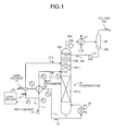
- FIG. 1 is a schematic of a structure of the CO 2 recovery unit according to the first embodiment.
- Fig. 2A is a schematic of a heat balance of a lean solvent and a rich solvent in a heat exchanger included in the CO 2 recovery unit according to the first embodiment.
- Fig. 2B is a schematic of a test example of the heat balance of the lean solvent and the rich solvent in the heat exchanger of the CO 2 recovery unit according to the first embodiment.
- the same structures as those in the CO 2 recovery unit shown in Fig. 5 are given the same reference signs, and redundant explanations thereof are omitted herein.
- Fig. 1 the same structures as those in the CO 2 recovery unit shown in Fig. 5 are given the same reference signs, and redundant explanations thereof are omitted herein.
- Fig. 1 the same structures as those in the CO 2 recovery unit shown in Fig. 5 are given the same reference signs, and redundant explanations thereof are omitted herein.
- Fig. 1 the same structures as those in the CO 2 recovery unit
- the CO 2 recovery unit includes: a CO 2 absorber (not shown) that brings flue gas containing CO 2 into contact with CO 2 absorbent to reduce the CO 2 contained in the flue gas; a regenerator 18 that reduces CO 2 contained in rich solvent 17 that has absorbed CO 2 in the CO 2 absorber to regenerate the rich solvent 17, so that lean solvent 15 having CO 2 reduced in the regenerator 18 is reused in the CO 2 absorber; a rich/lean solvent heat exchanger (hereinafter, "heat exchanger") 23 that allows the rich solvent 17 to exchange heat with the lean solvent 15; and a controller 40 that controls to extract rich solvent portion 17-2 that is part of the rich solvent 17, to allow the rich solvent portion 17-2 to bypass the heat exchanger 23, and to be supplied into the top of the regenerator 18 without exchanging heat, so as to minimize the sum (E1+E2) of an enthalpy (E1) that is taken
- the references sign 18A-1 denotes to a first regenerating unit
- the references sign 18A-2 denotes to a second regenerating unit
- the references sign 18B denotes to a washing unit
- the references sign 18C denotes to a demister
- the references sign L 1 denotes to a rich solvent supplying line
- the references sign L 2 denotes to a lean solvent supplying line
- the references sign L 3 denotes to a split rich solvent supplying line
- the references sign 41 denotes to an adjusting valve inserted into the split rich solvent supplying line L 3
- the references sign F denotes to a flow meter.
- the rich solvent portion 17-2 that is part of the rich solvent 17 is split into the split rich solvent supplying line L 3 , supplied into the regenerator 18, stripped in the first regenerating unit 18A-1 included in the regenerator 18 by way of steam rising from the bottom of the regenerator 18 to release CO 2 gas.
- the released CO 2 gas is taken out from the top of the regenerator 18 as the CO 2 gas 26a accompanying steam.
- the extracted rich solvent portion 17-2 does not exchange heat in the heat exchanger 23, the temperature of the rich solvent remains low, maintaining a great heat exchange capacity. This heat exchange capacity allows the rich solvent portion 17-2 to exchange heat with steam in the first regenerating unit 18A-1.
- a less amount of the enthalpy (E1) is taken out of the regenerator 18 as the CO 2 gas 26a accompanying steam, in comparison with a scenario without splitting the rich solvent 17.
- a major rich solvent portion 17-1 having exchanged heat in the heat exchanger 23 is supplied into an intermittent area of the regenerator 18, and stripped in the second regenerating unit 18A-2 in the regenerator 18 by way of steam rising from the bottom of the regenerator 18 to release CO 2 gas.
- the enthalpy (E2) of the lean solvent 15 after exchanging heat in the heat exchanger 23 is obtained.
- the enthalpy (E1) that is taken out as the CO 2 gas 26a accompanying steam is also obtained.
- an adjusting valve 41 is adjusted to adjust the amount of the rich solvent 17 to be split under an instruction of the controller 40, so as to minimize the sum of the enthalpy (E2) and the enthalpy (E1).
- the enthalpy (E1) that is taken out as the CO 2 gas 26a accompanying steam can be obtained based on a temperature (T 4 ) and the pressure of the CO 2 gas 26a that is taken out accompanying steam, and the amount of the recovered CO 2 .
- the enthalpy (E2) of the lean solvent after exchanging heat can be obtained based on a difference between a temperature (T 6 ) of the lean solvent 15 after exchanging heat in the heat exchanger 23 and the temperature (T 1 ) of the rich solvent 17 before exchanging heat in the heat exchanger 23, and the flow rate and the pressure of the lean solvent.
- a ratio of the rich solvent portion 17-2 to be bypassed differs depending on a plant facility; however, it is preferable to set the ratio approximately between 3 to 15 percent by weight. This is because, if the ratio is not within this range, the sum of the enthalpies (E1+E2) will not be minimized.
- the controller 40 preferably controls to approximate a temperature difference at an entering side of the heat exchanger 23 [(the temperature of the lean solvent 15 (T 6 ) - the temperature of rich the solvent 17 (T 1 )): ⁇ T a ] and a temperature difference at an exiting side of the heat exchanger 23 [(the temperature of the lean solvent 15 (T 5 ) - the temperature of the rich solvent 17 (T 2 )): ⁇ T b ] ( ⁇ T a ⁇ T b ).
- the rich solvent absorbs CO 2 gas in the CO 2 absorber, the rich solvent becomes greater in volume approximately by 10 percent. Therefore, to make the heat exchange performed in the heat exchanger suitable, the temperature differences should be brought to the same level. In this manner, the efficiency of the heat exchange can be made ideal.
- the temperature difference at the entering side of the heat exchanger 23 was [(the temperature of the lean solvent 15 (T 6 : 60.0 degrees Celsius) - the temperature of the rich solvent 17 (T 1 : 52.0 degrees Celsius)) ⁇ T a : 8.0 degrees Celsius], and the temperature difference at the exiting side of the heat exchanger 23 was [(the temperature of the lean solvent 15 (T 5 : 109.4 degrees Celsius) - the temperature of the rich solvent 17 (T 2 : 96.8 degrees Celsius)) ⁇ T b : 12.6 degrees Celsius], respectively, and these temperature differences were not approximate.
- the temperature difference at the entering side of the heat exchanger 23 was [(the temperature of the lean solvent 15 (T 6 : 62.1 degrees Celsius) - the temperature of the rich solvent 17 (T 1 : 52.0 degrees Celsius)) ⁇ T a : 10.1 degrees Celsius], and the temperature difference at the exiting side of the heat exchanger 23 was [(the temperature of the lean solvent 15 (T 5 : 109.4 degrees Celsius) - the temperature of the rich solvent 17 (T 2 : 99.3 degrees Celsius)) ⁇ T b : 10.1 degrees Celsius], and the temperature differences were the same.
- the heat balance of the entire system is taken into account.
- the amount of steam supplied into a regenerating heater 24 can be dramatically reduced.
- the heat of steam to be taken out from the top of the regenerator can be recovered to increase the temperature of the rich solvent, as well as to regenerate the rich solvent. In this manner, less amount of energy is required to supply steam in the regenerating heater 24 that generates steam for regeneration of the absorbent.
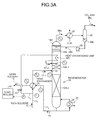
- FIGs. 3A and 3B are schematics of structures of the CO 2 recovery unit according to the second embodiment.
- the CO 2 recovery unit according to the second embodiment includes a first heat exchanging unit 18D that allows the rich solvent portion 17-2 bypassed and introduced from the top of the regenerator 18 to exchange heat at the top of the regenerator.
- the rich solvent portion 17-2 that is temporarily is brought into the regenerator 18 is heated by way of rising steam, having the temperature thereof (T 7 ) increased by the time of being released into the regenerator 18.
- the amount of steam used in the regenerating heater 24 can be further reduced, in comparison with the first embodiment, further to improve the heat efficiency of the entire system.
- the steam was supplied into the bottom of the regenerator 18 at the temperature of 140 degrees Celsius (to); after the major rich solvent portion 17-1 was stripped by way of rising steam to release CO 2 gas in the second regenerating unit 18A-2, the temperature of the steam was 86 degrees Celsius (t 1 ); and the temperature of the steam after passing through the first regenerating unit 18A-1 was 82 degrees Celsius (t 3 ).
- the rich solvent portion 17-2 was then temporarily brought into the regenerator 18 at the temperature of 52 degrees Celsius (T 1 ). After the heat exchange, the temperature of the rich solvent increased to 62 degrees Celsius (T 7 ).
- FIGs. 4A and 4B are schematics of structures of the CO 2 recovery unit according to the third embodiment.
- the CO 2 recovery unit according to the third embodiment includes a second heat exchanging unit 18E that allows the CO 2 gas 26a accompanying steam, taken out from the regenerator 18, to exchange heat with the bypassed rich solvent portion 17-2.
- the rich solvent portion 17-2 that is before being supplied into the regenerator 18 exchanges heat with the CO 2 gas 26a accompanying steam that is to be released out, the rich solvent portion 17-2 is heated by steam, having the temperature thereof (T 8 ) increased, by the time the rich solvent portion 17-2 is released into the regenerator 18.
- the amount of steam used in the regenerating heater 24 can be further reduced, in comparison with the first embodiment, improving the heat efficiency of the entire system further.
- the steam was supplied into the bottom of the regenerator 18 at the temperature of 140 degrees Celsius (to); after the major rich solvent portion 17-1 was stripped by way of rising steam to release CO 2 gas in the second regenerating unit 18A-2, the temperature of the steam was 86 degrees Celsius (t 1 ); and the temperature of the steam after passing through the first regenerating unit 18A-1 was 82 degrees Celsius (t 3 ). The steam was released out of the regenerator 18 at the temperature of 80 degrees Celsius (T 4 ). The temperature of the rich solvent portion 17-2 was 52 degrees Celsius (T 1 ). After the heat exchange performed in the second heat exchanging unit 18E, the temperature increased to 62 degrees Celsius (T 8 ).
Landscapes
- Chemical & Material Sciences (AREA)
- Engineering & Computer Science (AREA)
- Analytical Chemistry (AREA)
- General Chemical & Material Sciences (AREA)
- Oil, Petroleum & Natural Gas (AREA)
- Chemical Kinetics & Catalysis (AREA)
- Health & Medical Sciences (AREA)
- Biomedical Technology (AREA)
- Environmental & Geological Engineering (AREA)
- Treating Waste Gases (AREA)
- Gas Separation By Absorption (AREA)
- Carbon And Carbon Compounds (AREA)
Abstract
Description
- The present invention relates to a CO2 recovery unit and a CO2 recovery method that can dramatically reduce the amount of energy used in regenerating a CO2 absorbent in a CO2 recovery process.
- It has come to be pointed out that one of the causes of the global warming is a greenhouse effect of CO2, and it has become an urgent task, also internationally, to provide a countermeasure for CO2 to protect the global environment against the warming. CO2 is generated by any human activities combusting fossil fuels, and there are increasing demands for suppressing CO2 emissions. Along with such an increasing demand, researchers are energetically investigating a method for reducing and recovering CO2 included in flue gas, to apply in a power plant that consumes a large amount of fossil fuels, such as a thermal plant. In such a method, flue gas emitted from a steam generator is brought into contact with an amine-based CO2 absorbent to allow such absorbent to absorb the CO2, and the recovered CO2 is stored therein without being released into the air. As processes for reducing and recovering CO2 from the flue gas using the CO2 absorbent, Japanese Patent Application Laid-open No.
H3-193116 - As shown in
Fig. 5 , a conventional CO2 recovering apparatus 100 as mentioned above includes aflue gas cooler 14, a CO2 absorber 16, and aregenerator 18. Theflue gas cooler 14cools flue gas 12 containing CO2 emitted from anindustrial combustion facility 11, such as a steam generator or a gas turbine, withcooling water 13. The CO2 absorber 16 further includes a CO2 recovering unit 16A.
The CO2 recoveringunit 16A brings theflue gas 12, containing the cooled CO2, into contact with CO2 absorbent (hereinafter, also referred to as "absorbent") 15 that absorbs CO2, to reduce CO2 in theflue gas 12. Theregenerator 18 causes CO2 absorbent (hereinafter, also referred to as "rich solvent") 17 that has absorbed CO2 to release CO2 to regenerate the CO2 absorbent.
In the CO2 recovering apparatus 100, the regenerated CO2 absorbent (hereinafter, also referred to as "lean solvent") 15 having CO2 reduced in theregenerator 18 is reused in the CO2 absorber 16 as the CO2 absorbent. - By a CO2 recovering method using the CO2 recovering apparatus 100, a flue
gas booster fan 20 raises the pressure of theflue gas 12 emitted from an industrial combustion facility such as a steam generator or a gas turbine and containing CO2. Theflue gas 12 is then sent into theflue gas cooler 14, cooled by way of thecooling water 13, and then sent into the CO2 absorber 16. - The CO2 absorber 16 then brings the
flue gas 12 in a counter-current contact with the CO2 absorbent 15 that is based on amine-based solvent, allowing the CO2 absorbent 15 to absorb the CO2 contained in theflue gas 12 by way of chemical reaction.
Awashing unit 16B, included in the CO2 absorber 16, brings the flue gas having CO2 reduced in the CO2 recovering unit 16A into a gas-liquid contact with circulatingcondensate water 19. Thecondensate water 19 contains the CO2 absorbent, and is supplied via a nozzle included in awashing unit 16B. In this manner, the CO2 absorbent 15 that has accompanied the flue gas having CO2 reduced is recovered.Flue gas 12 having CO2 reduced is released out of the system.
Arich solvent pump 22 increases the pressure of the rich solvent that is the CO2 absorbent 17 that has absorbed CO2. Then, a rich/leansolvent heat exchanger 23 heats the rich solvent by way of the CO2 absorbent 15 that is lean solvent regenerated by theregenerator 18, and supplied into theregenerator 18. - The rich solvent discharged into the
regenerator 18 through the top thereof causes an endothermal reaction, thus releasing a majority of CO2. The CO2 absorbent that has released some or a majority of CO2 in theregenerator 18 is called semi-lean solvent. By the time the semi-lean solvent reaches the bottom of theregenerator 18, almost all of the CO2 is removed, turning the semi-lean solvent into the absorbent 15. A regeneratingheater 24 then heats the lean solvent by way ofsteam 25, supplying steam inside theregenerator 18.
CO2 gas 26a is guided out from the top of theregenerator 18, together with the steam that has been released from the rich solvent and semi-lean solvent in theregenerator 18. Acondenser 27 then condenses steam contained in the CO2 gas 26, and aseparation drum 28 separateswater 26b from the CO2 gas 26. The CO2 gas 26c is then released out of the system, and recovered separately. The recovered CO2 gas 26c is injected into an oilfield using enhanced oil recovery (EOR) method, or stored in an aquifer as a countermeasure for global warming.
Thewater 26b separated in theseparation drum 28 is pumped up to the top of theregenerator 18 by way of a condensed-water circulating pump 29. The rich/leansolvent heat exchanger 23 cools the regenerated CO2 absorbent (lean solvent) 15 by way of therich solvent 17. Alean solvent pump 30 then increases the pressure of thelean solvent 15. After being cooled down by alean solvent cooler 31, thelean solvent 15 is supplied into the CO2 absorber 16. - In
Fig. 5 , thereference numeral 11a denotes to a flue for theflue gas 12; thereference numeral 11b denotes to a stack; and thereference numeral 32 denotes to steam-condensed water. The CO2 recovering apparatus may be either added to an existing flue gas source to recover CO2, or installed with a flue gas source that is to be newly installed. A door that can be opened and closed is attached on thestack 11b. The door is closed while the CO2 recovering apparatus is operating, and opened while the flue gas source is operating but the CO2 recovering apparatus is not operating. - As a method for releasing CO2 gas from the
rich solvent 17 that has absorbed CO2 to regenerate the absorbent, steam stripping is used. According to this method, the absorbent is boiled in the regeneratingheater 24 to generate steam. The absorbent is heated thereby in theregenerator 18, and is regenerated by way of a steam-stripping effect thereof. - Disadvantageously, this method has a high heat loss, because steam is released out of the steam system by accompanying the CO2 gas 26a that is brought out of the
regenerator 18. - In response to this issue, according to a suggestion disclosed in Japanese Patent Application Laid-open No.
55-9079 -
- [PATENT LITERATURE 1] Japanese Patent Application Laid-open No.
H3-193116 - [PATENT LITERATURE 2] Japanese Patent Application Laid-open No.
S55-9079 - However, according to the amine regenerating method disclosed in the Japanese Patent Application Laid-open No.
S55-9079 - The present invention is made in consideration of the above, and an object of the present invention is to provide a CO2 recovery unit and a CO2 recovery method that can dramatically reduce the amount of energy used in regenerating an absorbent by considering an enthalpy of the system of CO2 absorbing apparatus.
- According to an aspect of the present invention, a CO2 recovery unit, which includes a CO2 absorber that brings flue gas containing CO2 into contact with a CO2 absorbent to reduce the CO2 contained in the flue gas, and a regenerator that reduces CO2 contained in rich solvent absorbing CO2 in the CO2 absorber to regenerate the rich solvent, so that lean solvent from which the CO2 is reduced in the regenerator is reused in the CO2 absorber, includes: a heat exchanger that allows the rich solvent to exchange heat with the lean solvent; and a controller that controls to extract part of the rich solvent to allow the part to bypass the heat exchanger, and to be supplied into a top of the regenerator without exchanging heat so as to minimize a sum of an enthalpy that is taken out of the regenerator as CO2 gas accompanying steam and an enthalpy that is a result of subtracting an enthalpy of the rich solvent before heat exchange in the heat exchanger from an enthalpy of the lean solvent after the heat exchange.
- Advantageously, in the CO2 recovery unit, control is performed to approximate a temperature difference between the rich solvent and the lean solvent at an entering side of the heat exchanger and a temperature difference between the rich solvent and the lean solvent at an exiting side of the heat exchanger.
- Advantageously, in the CO2 recovery unit, the part of the rich solvent that has bypassed the heat exchanger accounts for 3 to 15 percent by weight of the rich solvent.
- Advantageously, the CO2 recovery unit further includes a first heat exchanging unit that allows the part of the rich solvent that has bypassed the heat exchanger and been guided into the top of the regenerator to exchange heat in an upper section of the regenerator.
- Advantageously, the CO2 recovery unit further includes a second heat exchanging unit that allows the part of the rich solvent that has bypassed the heat exchanger to exchange heat with the CO2 gas accompanying steam extracted from the regenerator.
- According to another aspect of the present invention, a CO2 recovery method, for a CO2 absorber that brings flue gas containing CO2 into contact with a CO2 absorbent to reduce the CO2 contained in the flue gas, and a regenerator that reduces CO2 contained in rich solvent absorbing CO2 in the CO2 absorber to regenerate the rich solvent, so that lean solvent from which the CO2 is reduced in the regenerator is reused in the CO2 absorber, includes: allowing the rich solvent to exchange heat with the lean solvent; and controlling to extract part of the rich solvent to allow the part to bypass the heat exchanger, and to be supplied into a top of the regenerator without exchanging heat so as to minimize a sum of an enthalpy that is taken out of the regenerator as CO2 gas accompanying steam and an enthalpy that is a result of subtracting an enthalpy of the rich solvent before heat exchange in the heat exchanger from an enthalpy of the lean solvent after the heat exchange.
- Advantageously, the CO2 recovery method further includes allowing the part of the rich solvent that has bypassed the heat exchanger and been guided into the top of the regenerator to exchange heat in an upper section of the regenerator.
- Advantageously, the CO2 recovery method further includes allowing the part of the rich solvent that has bypassed the heat exchanger to exchange heat with the CO2 gas accompanying steam extracted from the regenerator.
- According to the present invention, the heat balance of the entire system can be taken into account. As a result, the amount of steam supplied into the reheater can be dramatically reduced.
-
-
Fig. 1 is a schematic of a structure of a CO2 recovery unit according to a first embodiment of the present invention; -
Fig. 2A is a schematic of a heat balance of a lean solvent and a rich solvent in a heat exchanger included in the CO2 recovery unit shown inFig. 1 ; -
Fig. 2B is a schematic of a test example of the heat balance of the lean solvent and the rich solvent in the heat exchanger of the CO2 recovery unit shown inFig. 1 ; -
Fig. 3A is a schematic of a structure of a CO2 recovery unit according to a second embodiment of the present invention; -
Fig. 3B is another schematic of the structure of the CO2 recovery unit according to the second embodiment; -
Fig. 4A is a schematic of a structure of a CO2 recovery unit according to a third embodiment of the present invention; -
Fig. 4B is another schematic of the structure of the CO2 recovery unit according to the third embodiment; and -
Fig. 5 is an exemplary structure of a conventional CO2 recovery unit. - Embodiments of a CO2 recovery unit according to the present invention will now be explained in detail with reference to the drawings. The embodiments disclosed herein are not intended to limit the scope of the present invention in any way.
- A CO2 recovery unit according to a first embodiment of the present invention will now be explained with reference to
Fig. 1 .
Fig. 1 is a schematic of a structure of the CO2 recovery unit according to the first embodiment.Fig. 2A is a schematic of a heat balance of a lean solvent and a rich solvent in a heat exchanger included in the CO2 recovery unit according to the first embodiment.Fig. 2B is a schematic of a test example of the heat balance of the lean solvent and the rich solvent in the heat exchanger of the CO2 recovery unit according to the first embodiment.
InFig. 1 , the same structures as those in the CO2 recovery unit shown inFig. 5 are given the same reference signs, and redundant explanations thereof are omitted herein.Fig. 1 depicts the CO2 regenerator 18 included in the CO2 recovery unit 100 explained above.
As shown inFig. 1 , the CO2 recovery unit according to the first embodiment includes: a CO2 absorber (not shown) that brings flue gas containing CO2 into contact with CO2 absorbent to reduce the CO2 contained in the flue gas; aregenerator 18 that reduces CO2 contained in rich solvent 17 that has absorbed CO2 in the CO2 absorber to regenerate the rich solvent 17, so that lean solvent 15 having CO2 reduced in theregenerator 18 is reused in the CO2 absorber; a rich/lean solvent heat exchanger (hereinafter, "heat exchanger") 23 that allows the rich solvent 17 to exchange heat with the lean solvent 15; and acontroller 40 that controls to extract rich solvent portion 17-2 that is part of the rich solvent 17, to allow the rich solvent portion 17-2 to bypass theheat exchanger 23, and to be supplied into the top of theregenerator 18 without exchanging heat, so as to minimize the sum (E1+E2) of an enthalpy (E1) that is taken out of theregenerator 18 as the CO2 gas 26a accompanying steam, and an enthalpy (E2) that is the result of subtracting an enthalpy of the rich solvent 17 before exchanging heat in theheat exchanger 23 from an enthalpy of the lean solvent 15 after exchanging heat.
InFig. 1 , the references sign 18A-1 denotes to a first regenerating unit; the references sign 18A-2 denotes to a second regenerating unit; the references sign 18B denotes to a washing unit; the references sign 18C denotes to a demister; the references sign L1 denotes to a rich solvent supplying line; the references sign L2 denotes to a lean solvent supplying line; the references sign L3 denotes to a split rich solvent supplying line; the references sign 41 denotes to an adjusting valve inserted into the split rich solvent supplying line L3; and the references sign F denotes to a flow meter. - According to the first embodiment, the rich solvent portion 17-2 that is part of the rich solvent 17 is split into the split rich solvent supplying line L3, supplied into the
regenerator 18, stripped in thefirst regenerating unit 18A-1 included in theregenerator 18 by way of steam rising from the bottom of theregenerator 18 to release CO2 gas. The released CO2 gas is taken out from the top of theregenerator 18 as the CO2 gas 26a accompanying steam.
Because the extracted rich solvent portion 17-2 does not exchange heat in theheat exchanger 23, the temperature of the rich solvent remains low, maintaining a great heat exchange capacity. This heat exchange capacity allows the rich solvent portion 17-2 to exchange heat with steam in thefirst regenerating unit 18A-1.
As a result, a less amount of the enthalpy (E1) is taken out of theregenerator 18 as the CO2 gas 26a accompanying steam, in comparison with a scenario without splitting the rich solvent 17. - A major rich solvent portion 17-1 having exchanged heat in the
heat exchanger 23 is supplied into an intermittent area of theregenerator 18, and stripped in thesecond regenerating unit 18A-2 in theregenerator 18 by way of steam rising from the bottom of theregenerator 18 to release CO2 gas. - According to the present invention, the enthalpy (E2) of the lean solvent 15 after exchanging heat in the
heat exchanger 23 is obtained. The enthalpy (E1) that is taken out as the CO2 gas 26a accompanying steam is also obtained. Then, an adjustingvalve 41 is adjusted to adjust the amount of the rich solvent 17 to be split under an instruction of thecontroller 40, so as to minimize the sum of the enthalpy (E2) and the enthalpy (E1). - The enthalpy (E1) that is taken out as the CO2 gas 26a accompanying steam can be obtained based on a temperature (T4) and the pressure of the CO2 gas 26a that is taken out accompanying steam, and the amount of the recovered CO2.
The enthalpy (E2) of the lean solvent after exchanging heat can be obtained based on a difference between a temperature (T6) of the lean solvent 15 after exchanging heat in theheat exchanger 23 and the temperature (T1) of the rich solvent 17 before exchanging heat in theheat exchanger 23, and the flow rate and the pressure of the lean solvent. - A ratio of the rich solvent portion 17-2 to be bypassed differs depending on a plant facility; however, it is preferable to set the ratio approximately between 3 to 15 percent by weight.
This is because, if the ratio is not within this range, the sum of the enthalpies (E1+E2) will not be minimized. - Furthermore, as shown in
Fig. 2A , thecontroller 40 preferably controls to approximate a temperature difference at an entering side of the heat exchanger 23 [(the temperature of the lean solvent 15 (T6) - the temperature of rich the solvent 17 (T1)): ΔTa] and a temperature difference at an exiting side of the heat exchanger 23 [(the temperature of the lean solvent 15 (T5) - the temperature of the rich solvent 17 (T2)): ΔTb] (ΔTa≈ΔTb).
At this time, because the rich solvent absorbs CO2 gas in the CO2 absorber, the rich solvent becomes greater in volume approximately by 10 percent. Therefore, to make the heat exchange performed in the heat exchanger suitable, the temperature differences should be brought to the same level. In this manner, the efficiency of the heat exchange can be made ideal. - More specifically, when part of the rich solvent 17 was not split, as shown in
Fig. 2B , the temperature difference at the entering side of theheat exchanger 23 was [(the temperature of the lean solvent 15 (T6: 60.0 degrees Celsius) - the temperature of the rich solvent 17 (T1: 52.0 degrees Celsius)) ΔTa: 8.0 degrees Celsius], and the temperature difference at the exiting side of theheat exchanger 23 was [(the temperature of the lean solvent 15 (T5: 109.4 degrees Celsius) - the temperature of the rich solvent 17 (T2: 96.8 degrees Celsius)) ΔTb: 12.6 degrees Celsius], respectively, and these temperature differences were not approximate.
In contrast, when part of the rich solvent 17 was split as disclosed herein, the temperature difference at the entering side of theheat exchanger 23 was [(the temperature of the lean solvent 15 (T6: 62.1 degrees Celsius) - the temperature of the rich solvent 17 (T1: 52.0 degrees Celsius)) ΔTa: 10.1 degrees Celsius], and the temperature difference at the exiting side of theheat exchanger 23 was [(the temperature of the lean solvent 15 (T5: 109.4 degrees Celsius) - the temperature of the rich solvent 17 (T2: 99.3 degrees Celsius)) ΔTb: 10.1 degrees Celsius], and the temperature differences were the same. - In this manner, the heat exchange efficiency of the
heat exchanger 23 can be maximized. - A particular example of an operation performed by the CO2 recovery unit will now be explained.
- (1) The CO2 recovery unit is driven to recover CO2 from the flue gas.
- (2) When the circulation of the absorbent reaches a predetermined stability, a controller unit, not shown, controls to gradually open the adjusting
valve 41 so that part of the rich solvent 17 is split to the split rich solvent supplying line L3. - (3) The enthalpy (E1) taken out as the CO2 gas 26a accompanying steam is then obtained. The enthalpy (E2) of the lean solvent 15 after heat exchange is also obtained. A controller, not shown, controls to adjust the adjusting
valve 41 so as to minimize the sum of the enthalpy (E1) and the enthalpy (E2). - (4) While the operation is kept running, the
controller 40 constantly monitors to keep the sum of the enthalpies to the minimum. - By controlling according to the present invention, the heat balance of the entire system is taken into account. As a result, the amount of steam supplied into a regenerating
heater 24 can be dramatically reduced. - A test was performed using an amine-based solution as the CO2 absorbent to recover 29.0Nm/H (57.0Kg/H) of carbon dioxide. In this test setting, according to the conventional method where no part of the rich solvent 17 that is to be supplied into the
regenerator 18 was split, the temperature of the CO2 gas 26a that is taken out from the top of theregenerator 18 accompanying steam was 87 degrees Celsius.
On the contrary, as shown inFig. 1 , when the portion 17-2 of the rich solvent 17 was split to minimize the sum (E1+E2) of the enthalpy (E1) taken out of theregenerator 18 as the CO2 gas 26a accompanying steam, and the enthalpy (E2) of the lean solvent 15 after exchanging heat with the rich solvent 17 in the heat exchanger 23 (33.1kg/H that was approximately 5 percent of 681.1kg/H of the rich solvent 17 was split), the temperature of the CO2 gas 26a accompanying steam declined to 60 degrees Celsius.
At this time, the heat lost in the lean solvent 15 was 1,310Kcal/H, and the heat gained at the top of theregenerator 18 was 4,830Kcal/H. The amount of steam corresponding to the energy of 3,520Kcal/H that is the difference between these two was reduced. - Therefore, approximately 7.5 percent of 46,800Kcal/H that is the amount of steam used in the regenerating
heater 24 was reduced to improve the heat efficiency of the entire system. - In other words, according to the present invention, the heat of steam to be taken out from the top of the regenerator can be recovered to increase the temperature of the rich solvent, as well as to regenerate the rich solvent. In this manner, less amount of energy is required to supply steam in the regenerating
heater 24 that generates steam for regeneration of the absorbent. - A CO2 recovery unit according to a second embodiment of the present invention will now be explained with reference to
Figs. 3A and3B .
Figs. 3A and3B are schematics of structures of the CO2 recovery unit according to the second embodiment. In these drawings, the same structures as those in the CO2 recovery unit shown inFig. 1 are given the same references signs, and redundant explanations thereof are omitted herein.
As shown inFig. 3A , the CO2 recovery unit according to the second embodiment includes a firstheat exchanging unit 18D that allows the rich solvent portion 17-2 bypassed and introduced from the top of theregenerator 18 to exchange heat at the top of the regenerator.
In the firstheat exchanging unit 18D, the rich solvent portion 17-2 that is temporarily is brought into theregenerator 18 is heated by way of rising steam, having the temperature thereof (T7) increased by the time of being released into theregenerator 18. - Therefore, the amount of steam used in the regenerating
heater 24 can be further reduced, in comparison with the first embodiment, further to improve the heat efficiency of the entire system. - More specifically, as shown in the temperature distribution in
Fig. 4B , the steam was supplied into the bottom of theregenerator 18 at the temperature of 140 degrees Celsius (to); after the major rich solvent portion 17-1 was stripped by way of rising steam to release CO2 gas in thesecond regenerating unit 18A-2, the temperature of the steam was 86 degrees Celsius (t1); and the temperature of the steam after passing through thefirst regenerating unit 18A-1 was 82 degrees Celsius (t3). The rich solvent portion 17-2 was then temporarily brought into theregenerator 18 at the temperature of 52 degrees Celsius (T1). After the heat exchange, the temperature of the rich solvent increased to 62 degrees Celsius (T7). - As a result, it has been demonstrated that, when the amount of used steam was 120kg/H, a reduction by 13.4kg/H was achieved, accounting for 12 percent of a steam reduction. At this time, the lean solvent was let out from the
regenerator 18 at the temperature of 109.4 degrees Celsius (T5); after exchanging heat in theheat exchanger 23, the temperature of the rich solvent was 99.3 degrees Celsius (T2); and 10 percent of the rich solvent portion 17-2 was split. - A CO2 recovery unit according to a third embodiment of the present invention will now be explained with reference to
Figs. 4A and4B .
Figs. 4A and4B are schematics of structures of the CO2 recovery unit according to the third embodiment. In these drawings, the same structures as those in the CO2 recovery unit shown inFig. 1 are given the same references signs, and redundant explanations thereof are omitted herein.
As shown inFig. 4A , the CO2 recovery unit according to the third embodiment includes a secondheat exchanging unit 18E that allows the CO2 gas 26a accompanying steam, taken out from theregenerator 18, to exchange heat with the bypassed rich solvent portion 17-2.
Because the rich solvent portion 17-2 that is before being supplied into theregenerator 18 exchanges heat with the CO2 gas 26a accompanying steam that is to be released out, the rich solvent portion 17-2 is heated by steam, having the temperature thereof (T8) increased, by the time the rich solvent portion 17-2 is released into theregenerator 18. - Therefore, the amount of steam used in the regenerating
heater 24 can be further reduced, in comparison with the first embodiment, improving the heat efficiency of the entire system further. - More specifically, as shown in the temperature distribution in the
Fig. 2B , the steam was supplied into the bottom of theregenerator 18 at the temperature of 140 degrees Celsius (to); after the major rich solvent portion 17-1 was stripped by way of rising steam to release CO2 gas in thesecond regenerating unit 18A-2, the temperature of the steam was 86 degrees Celsius (t1); and the temperature of the steam after passing through thefirst regenerating unit 18A-1 was 82 degrees Celsius (t3). The steam was released out of theregenerator 18 at the temperature of 80 degrees Celsius (T4). The temperature of the rich solvent portion 17-2 was 52 degrees Celsius (T1). After the heat exchange performed in the secondheat exchanging unit 18E, the temperature increased to 62 degrees Celsius (T8). - As a result, it has been demonstrated that, when the amount of used steam was 120kg/H, a reduction by 13.4kg/H was achieved, accounting for 12 percent of a steam reduction. At this time, the lean solvent was let out from the
regenerator 18 at the temperature of 109.4 degrees Celsius (T5); after exchanging heat in theheat exchanger 23, the temperature of the rich solvent was 99.3 degrees Celsius (T2); and 10 percent of the rich solvent portion 17-2 was split.
Claims (8)
- A CO2 recovery unit, which includes a CO2 absorber (16) that brings flue gas containing CO2 into contact with a CO2 absorbent to reduce the CO2 contained in the flue gas, and a regenerator (18) that reduces CO2 contained in rich solvent absorbing CO2 in the CO2 absorber (16) to regenerate the rich solvent, so that lean solvent from which the CO2 is reduced in the regenerator (18) is reused in the CO2 absorber (16), comprising:a heat exchanger (23) that allows the rich solvent to exchange heat with the lean solvent; andcharacterized in that it further comprises
a controller (40) that controls to extract part of the rich solvent to allow the part to bypass the heat exchanger (23), and to be supplied into a top of the regenerator (18) without exchanging heat so as to minimize a sum of an enthalpy that is taken out of the regenerator (18) as CO2 gas accompanying steam and an enthalpy that is a result of subtracting an enthalpy of the rich solvent before heat exchange in the heat exchanger (23) from an enthalpy of the lean solvent after the heat exchange. - The CO2 recovery unit according to claim 1, wherein control is performed to approximate a temperature difference between the rich solvent and the lean solvent at an entering side of the heat exchanger (23) and a temperature difference between the rich solvent and the lean solvent at an exiting side of the heat exchanger (23).
- The CO2 recovery unit according to claim 1 or 2, wherein the part of the rich solvent that has bypassed the heat exchanger (23) accounts for 3 to 15 percent by weight of the rich solvent.
- The CO2 recovery unit according to any one of claims 1 to 3 further comprising a first heat exchanging unit (18D) that allows the part of the rich solvent that has bypassed the heat exchanger (23) and been guided into the top of the regenerator (18) to exchange heat in an upper section of the regenerator (18).
- The CO2 recovery unit according to any one of claims 1 to 4 further comprising a second heat exchanging unit (18E) that allows the part of the rich solvent that has bypassed the heat exchanger (23) to exchange heat with the CO2 gas accompanying steam extracted from the regenerator (18).
- A CO2 recovery method, for a CO2 absorber (16) that brings flue gas containing CO2 into contact with a CO2 absorbent to reduce the CO2 contained in the flue gas, and a regenerator (18) that reduces CO2 contained in rich solvent absorbing CO2 in the CO2 absorber (16) to regenerate the rich solvent, so that lean solvent from which the CO2 is reduced in the regenerator (18) is reused in the CO2 absorber (16), comprising:allowing the rich solvent to exchange heat with the lean solvent; andcharacterized in that it further comprises
controlling to extract part of the rich solvent to allow the part to bypass the heat exchanger (23), and to be supplied into a top of the regenerator (18) without exchanging heat so as to minimize a sum of an enthalpy that is taken out of the regenerator (18) as CO2 gas accompanying steam and an enthalpy that is a result of subtracting an enthalpy of the rich solvent before heat exchange in the heat exchanger (23) from an enthalpy of the lean solvent after the heat exchange. - The CO2 recovery method according to claim 6 further comprising allowing the part of the rich solvent that has bypassed the heat exchanger (23) and been guided into the top of the regenerator (18) to exchange heat in an upper section of the regenerator (18).
- The CO2 recovery unit according to claim 6 further comprising allowing the part of the rich solvent that has bypassed the heat exchanger (23) to exchange heat with the CO2 gas accompanying steam extracted from the regenerator (18).
Applications Claiming Priority (1)
| Application Number | Priority Date | Filing Date | Title |
|---|---|---|---|
| JP2009144585A JP5383338B2 (en) | 2009-06-17 | 2009-06-17 | CO2 recovery device and CO2 recovery method |
Publications (2)
| Publication Number | Publication Date |
|---|---|
| EP2269712A1 true EP2269712A1 (en) | 2011-01-05 |
| EP2269712B1 EP2269712B1 (en) | 2012-10-24 |
Family
ID=42363191
Family Applications (1)
| Application Number | Title | Priority Date | Filing Date |
|---|---|---|---|
| EP10150434A Active EP2269712B1 (en) | 2009-06-17 | 2010-01-11 | CO2 recovery apparatus and CO2 recovery method |
Country Status (6)
| Country | Link |
|---|---|
| US (2) | US8414694B2 (en) |
| EP (1) | EP2269712B1 (en) |
| JP (1) | JP5383338B2 (en) |
| AU (1) | AU2010200175B1 (en) |
| CA (1) | CA2688966C (en) |
| DK (1) | DK2269712T3 (en) |
Cited By (14)
| Publication number | Priority date | Publication date | Assignee | Title |
|---|---|---|---|---|
| US8192530B2 (en) | 2007-12-13 | 2012-06-05 | Alstom Technology Ltd | System and method for regeneration of an absorbent solution |
| JP2013184090A (en) * | 2012-03-06 | 2013-09-19 | Toshiba Corp | Carbon dioxide recovery apparatus and carbon dioxide recovery method |
| EP2644250A1 (en) * | 2012-03-28 | 2013-10-02 | Mitsubishi Heavy Industries, Ltd. | Exhaust gas treatment system |
| CN103521051A (en) * | 2012-06-25 | 2014-01-22 | 株式会社东芝 | Carbon dioxide recovering apparatus and method for operating the same |
| US8864878B2 (en) | 2011-09-23 | 2014-10-21 | Alstom Technology Ltd | Heat integration of a cement manufacturing plant with an absorption based carbon dioxide capture process |
| US8911538B2 (en) | 2011-12-22 | 2014-12-16 | Alstom Technology Ltd | Method and system for treating an effluent stream generated by a carbon capture system |
| EP2772297A4 (en) * | 2011-10-28 | 2015-03-11 | Ihi Corp | METHOD FOR RECOVERING CARBON DIOXIDE AND RECOVERY DEVICE |
| US9028654B2 (en) | 2012-02-29 | 2015-05-12 | Alstom Technology Ltd | Method of treatment of amine waste water and a system for accomplishing the same |
| US9101912B2 (en) | 2012-11-05 | 2015-08-11 | Alstom Technology Ltd | Method for regeneration of solid amine CO2 capture beds |
| US9133407B2 (en) | 2011-02-25 | 2015-09-15 | Alstom Technology Ltd | Systems and processes for removing volatile degradation products produced in gas purification |
| EP3037152A3 (en) * | 2014-12-05 | 2016-10-26 | Kabushiki Kaisha Toshiba | Carbon dioxide capturing system and method of operating the same |
| CN104759188B (en) * | 2010-11-17 | 2017-06-30 | 株式会社东芝 | Carbon dioxide recovery plant and process for carbon dioxide recovery |
| NL2036131B1 (en) * | 2023-10-26 | 2025-05-12 | Carbonoro Tech B V | Process for removing co2 from gas |
| NL2036130B1 (en) * | 2023-10-26 | 2025-05-12 | Carbonoro Tech B V | Process for removing co2 from gas |
Families Citing this family (81)
| Publication number | Priority date | Publication date | Assignee | Title |
|---|---|---|---|---|
| AU2009228062B2 (en) | 2008-03-28 | 2014-01-16 | Exxonmobil Upstream Research Company | Low emission power generation and hydrocarbon recovery systems and methods |
| WO2009120779A2 (en) | 2008-03-28 | 2009-10-01 | Exxonmobil Upstream Research Company | Low emission power generation and hydrocarbon recovery systems and methods |
| EA026915B1 (en) | 2008-10-14 | 2017-05-31 | Эксонмобил Апстрим Рисерч Компани | Methods and systems for controlling the products of combustion |
| BRPI0924205B1 (en) * | 2009-01-28 | 2019-05-07 | Siemens Aktiengesellschaft | METHOD FOR SEPARATING CARBON DIOXIDE FROM EXHAUST GAS FROM A FOSSIL ENERGY POWER PLANT. |
| JP5317833B2 (en) * | 2009-05-28 | 2013-10-16 | 株式会社東芝 | Steam turbine power generation equipment |
| CA2777768C (en) | 2009-11-12 | 2016-06-07 | Exxonmobil Upstream Research Company | Low emission power generation and hydrocarbon recovery systems and methods |
| US9732673B2 (en) | 2010-07-02 | 2017-08-15 | Exxonmobil Upstream Research Company | Stoichiometric combustion with exhaust gas recirculation and direct contact cooler |
| BR112012031153A2 (en) | 2010-07-02 | 2016-11-08 | Exxonmobil Upstream Res Co | low emission triple-cycle power generation systems and methods |
| CN102971508B (en) | 2010-07-02 | 2016-06-01 | 埃克森美孚上游研究公司 | CO2 separation system and method for separating CO2 |
| EA029336B1 (en) | 2010-07-02 | 2018-03-30 | Эксонмобил Апстрим Рисерч Компани | Systems and method of generating power by stoichiometric combustion with enriched air and exhaust gas recirculation |
| GB2486476A (en) * | 2010-12-16 | 2012-06-20 | Doosan Power Systems Ltd | Method and apparatus for the regeneration of a capture medium |
| TWI563165B (en) | 2011-03-22 | 2016-12-21 | Exxonmobil Upstream Res Co | Power generation system and method for generating power |
| TWI593872B (en) | 2011-03-22 | 2017-08-01 | 艾克頌美孚上游研究公司 | Integrated system and method of generating power |
| TWI564474B (en) | 2011-03-22 | 2017-01-01 | 艾克頌美孚上游研究公司 | Integrated systems for controlling stoichiometric combustion in turbine systems and methods of generating power using the same |
| TWI563166B (en) | 2011-03-22 | 2016-12-21 | Exxonmobil Upstream Res Co | Integrated generation systems and methods for generating power |
| CN104428490B (en) | 2011-12-20 | 2018-06-05 | 埃克森美孚上游研究公司 | The coal bed methane production of raising |
| JP6216490B2 (en) * | 2012-02-03 | 2017-10-18 | 三菱重工業株式会社 | CO2 recovery device |
| US9353682B2 (en) | 2012-04-12 | 2016-05-31 | General Electric Company | Methods, systems and apparatus relating to combustion turbine power plants with exhaust gas recirculation |
| US10273880B2 (en) | 2012-04-26 | 2019-04-30 | General Electric Company | System and method of recirculating exhaust gas for use in a plurality of flow paths in a gas turbine engine |
| US9784185B2 (en) | 2012-04-26 | 2017-10-10 | General Electric Company | System and method for cooling a gas turbine with an exhaust gas provided by the gas turbine |
| US10161312B2 (en) | 2012-11-02 | 2018-12-25 | General Electric Company | System and method for diffusion combustion with fuel-diluent mixing in a stoichiometric exhaust gas recirculation gas turbine system |
| US10107495B2 (en) | 2012-11-02 | 2018-10-23 | General Electric Company | Gas turbine combustor control system for stoichiometric combustion in the presence of a diluent |
| US9611756B2 (en) | 2012-11-02 | 2017-04-04 | General Electric Company | System and method for protecting components in a gas turbine engine with exhaust gas recirculation |
| US9574496B2 (en) | 2012-12-28 | 2017-02-21 | General Electric Company | System and method for a turbine combustor |
| US9599070B2 (en) | 2012-11-02 | 2017-03-21 | General Electric Company | System and method for oxidant compression in a stoichiometric exhaust gas recirculation gas turbine system |
| US9869279B2 (en) | 2012-11-02 | 2018-01-16 | General Electric Company | System and method for a multi-wall turbine combustor |
| US9803865B2 (en) | 2012-12-28 | 2017-10-31 | General Electric Company | System and method for a turbine combustor |
| US10215412B2 (en) | 2012-11-02 | 2019-02-26 | General Electric Company | System and method for load control with diffusion combustion in a stoichiometric exhaust gas recirculation gas turbine system |
| US9708977B2 (en) | 2012-12-28 | 2017-07-18 | General Electric Company | System and method for reheat in gas turbine with exhaust gas recirculation |
| US9631815B2 (en) | 2012-12-28 | 2017-04-25 | General Electric Company | System and method for a turbine combustor |
| US10208677B2 (en) | 2012-12-31 | 2019-02-19 | General Electric Company | Gas turbine load control system |
| US9581081B2 (en) | 2013-01-13 | 2017-02-28 | General Electric Company | System and method for protecting components in a gas turbine engine with exhaust gas recirculation |
| US9512759B2 (en) | 2013-02-06 | 2016-12-06 | General Electric Company | System and method for catalyst heat utilization for gas turbine with exhaust gas recirculation |
| TW201502356A (en) | 2013-02-21 | 2015-01-16 | Exxonmobil Upstream Res Co | Reducing oxygen in a gas turbine exhaust |
| US9938861B2 (en) | 2013-02-21 | 2018-04-10 | Exxonmobil Upstream Research Company | Fuel combusting method |
| WO2014133406A1 (en) | 2013-02-28 | 2014-09-04 | General Electric Company | System and method for a turbine combustor |
| US20140250945A1 (en) | 2013-03-08 | 2014-09-11 | Richard A. Huntington | Carbon Dioxide Recovery |
| CN105008499A (en) | 2013-03-08 | 2015-10-28 | 埃克森美孚上游研究公司 | Power generation and methane recovery from methane hydrates |
| TW201500635A (en) | 2013-03-08 | 2015-01-01 | Exxonmobil Upstream Res Co | Processing exhaust for use in enhanced oil recovery |
| US9618261B2 (en) | 2013-03-08 | 2017-04-11 | Exxonmobil Upstream Research Company | Power generation and LNG production |
| JP6157925B2 (en) * | 2013-05-20 | 2017-07-05 | 株式会社東芝 | Carbon dioxide separation and recovery device and operation method thereof |
| TWI654368B (en) | 2013-06-28 | 2019-03-21 | 美商艾克頌美孚上游研究公司 | System, method and media for controlling exhaust gas flow in an exhaust gas recirculation gas turbine system |
| US9617914B2 (en) | 2013-06-28 | 2017-04-11 | General Electric Company | Systems and methods for monitoring gas turbine systems having exhaust gas recirculation |
| US9835089B2 (en) | 2013-06-28 | 2017-12-05 | General Electric Company | System and method for a fuel nozzle |
| US9631542B2 (en) | 2013-06-28 | 2017-04-25 | General Electric Company | System and method for exhausting combustion gases from gas turbine engines |
| US9587510B2 (en) | 2013-07-30 | 2017-03-07 | General Electric Company | System and method for a gas turbine engine sensor |
| US9903588B2 (en) | 2013-07-30 | 2018-02-27 | General Electric Company | System and method for barrier in passage of combustor of gas turbine engine with exhaust gas recirculation |
| US9951658B2 (en) | 2013-07-31 | 2018-04-24 | General Electric Company | System and method for an oxidant heating system |
| US10030588B2 (en) | 2013-12-04 | 2018-07-24 | General Electric Company | Gas turbine combustor diagnostic system and method |
| US9752458B2 (en) | 2013-12-04 | 2017-09-05 | General Electric Company | System and method for a gas turbine engine |
| US10227920B2 (en) | 2014-01-15 | 2019-03-12 | General Electric Company | Gas turbine oxidant separation system |
| US9863267B2 (en) | 2014-01-21 | 2018-01-09 | General Electric Company | System and method of control for a gas turbine engine |
| US9915200B2 (en) | 2014-01-21 | 2018-03-13 | General Electric Company | System and method for controlling the combustion process in a gas turbine operating with exhaust gas recirculation |
| US10079564B2 (en) | 2014-01-27 | 2018-09-18 | General Electric Company | System and method for a stoichiometric exhaust gas recirculation gas turbine system |
| US10047633B2 (en) | 2014-05-16 | 2018-08-14 | General Electric Company | Bearing housing |
| US10655542B2 (en) | 2014-06-30 | 2020-05-19 | General Electric Company | Method and system for startup of gas turbine system drive trains with exhaust gas recirculation |
| US10060359B2 (en) | 2014-06-30 | 2018-08-28 | General Electric Company | Method and system for combustion control for gas turbine system with exhaust gas recirculation |
| US9885290B2 (en) | 2014-06-30 | 2018-02-06 | General Electric Company | Erosion suppression system and method in an exhaust gas recirculation gas turbine system |
| US9819292B2 (en) | 2014-12-31 | 2017-11-14 | General Electric Company | Systems and methods to respond to grid overfrequency events for a stoichiometric exhaust recirculation gas turbine |
| US9869247B2 (en) | 2014-12-31 | 2018-01-16 | General Electric Company | Systems and methods of estimating a combustion equivalence ratio in a gas turbine with exhaust gas recirculation |
| US10788212B2 (en) | 2015-01-12 | 2020-09-29 | General Electric Company | System and method for an oxidant passageway in a gas turbine system with exhaust gas recirculation |
| US10253690B2 (en) | 2015-02-04 | 2019-04-09 | General Electric Company | Turbine system with exhaust gas recirculation, separation and extraction |
| US10316746B2 (en) | 2015-02-04 | 2019-06-11 | General Electric Company | Turbine system with exhaust gas recirculation, separation and extraction |
| US10094566B2 (en) | 2015-02-04 | 2018-10-09 | General Electric Company | Systems and methods for high volumetric oxidant flow in gas turbine engine with exhaust gas recirculation |
| US10267270B2 (en) | 2015-02-06 | 2019-04-23 | General Electric Company | Systems and methods for carbon black production with a gas turbine engine having exhaust gas recirculation |
| US10145269B2 (en) | 2015-03-04 | 2018-12-04 | General Electric Company | System and method for cooling discharge flow |
| US10480792B2 (en) | 2015-03-06 | 2019-11-19 | General Electric Company | Fuel staging in a gas turbine engine |
| ITUB20156071A1 (en) * | 2015-12-02 | 2017-06-02 | Nuovo Pignone Tecnologie Srl | SYSTEM AND METHOD OF CONTROL FOR REMI CABINS |
| US20180216532A1 (en) * | 2017-01-31 | 2018-08-02 | General Electric Company | System and method for treating exhaust gas |
| JP7043249B2 (en) | 2017-12-27 | 2022-03-29 | 三菱重工エンジニアリング株式会社 | CO2 recovery device, CO2 recovery method |
| CA3098188A1 (en) * | 2018-04-24 | 2019-10-31 | Petroliam Nasional Berhad (Petronas) | System and method for solvent regeneration |
| CN109351125A (en) * | 2018-09-20 | 2019-02-19 | 湖南大学 | A novel catalytic desorption tower for reducing energy consumption for regeneration of CO2-rich amine solution |
| JP7152975B2 (en) * | 2019-03-20 | 2022-10-13 | 三菱重工エンジニアリング株式会社 | Absorbing liquid regeneration device, CO2 recovery device, and absorbing liquid regeneration method |
| JP7177734B2 (en) * | 2019-03-20 | 2022-11-24 | 三菱重工エンジニアリング株式会社 | ABSORBENT LIQUID REGENERATION DEVICE, CO2 RECOVERY DEVICE, AND METHOD OF MODIFYING ABSORBENT LIQUID REGENERATION DEVICE |
| CN109999618B (en) * | 2019-04-25 | 2024-05-14 | 华能国际电力股份有限公司 | System and method for separating carbon dioxide from medium-high pressure gas source |
| CN113842760A (en) * | 2021-10-15 | 2021-12-28 | 四川德胜集团钒钛有限公司 | A sintering flue gas treatment system and method |
| US20230166212A1 (en) * | 2021-11-30 | 2023-06-01 | University Of Kentucky Research Foundation | Automated co2 capture process control system with solvent property prediction |
| US20240307820A1 (en) * | 2023-03-16 | 2024-09-19 | Uop Llc | Solvent-based co2 capture process incorporating overhead vapor compression |
| CN116293762A (en) * | 2023-04-28 | 2023-06-23 | 秦皇岛玻璃工业研究设计院有限公司 | High hydrogen fuel flue gas treatment system and method |
| WO2025089950A1 (en) | 2023-10-26 | 2025-05-01 | Carbonoro Technology B.V. | Process for removing co2 from gas |
| CN119896968A (en) * | 2025-03-28 | 2025-04-29 | 深圳市深汕特别合作区华润电力有限公司 | A method and device for energy-saving analysis of amine solvents in carbon capture systems |
Citations (5)
| Publication number | Priority date | Publication date | Assignee | Title |
|---|---|---|---|---|
| US4146569A (en) * | 1976-07-13 | 1979-03-27 | Giuseppe Giammarco | Process for removing gaseous impurities from a gaseous mixture containing the same |
| US4152217A (en) * | 1978-06-30 | 1979-05-01 | Exxon Research & Engineering Co. | Amine regeneration process |
| WO2006118795A1 (en) * | 2005-04-29 | 2006-11-09 | Fluor Technologies Corporation | Configurations and methods for acid gas absorption and solvent regeneration |
| WO2008144918A1 (en) * | 2007-05-29 | 2008-12-04 | University Of Regina | Method and absorbent composition for recovering a gaseous component from a gas stream |
| WO2009112518A1 (en) * | 2008-03-13 | 2009-09-17 | Shell Internationale Research Maatschappij B.V. | Process for removal of carbon dioxide from a gas |
Family Cites Families (19)
| Publication number | Priority date | Publication date | Assignee | Title |
|---|---|---|---|---|
| US3563696A (en) * | 1969-06-17 | 1971-02-16 | Field And Epes | Separation of co2 and h2s from gas mixtures |
| GB1431767A (en) * | 1972-04-19 | 1976-04-14 | Petrocarbon Dev Ltd | Controlling the concentration of impurities in a gas stream |
| US4106916A (en) * | 1977-08-10 | 1978-08-15 | Phillips Petroleum Company | Automatic control of an absorption/stripping process |
| US4460383A (en) * | 1982-12-20 | 1984-07-17 | Black, Sivalls & Bryson | Method and apparatus for reconcentrating liquid absorbent |
| US5192341A (en) * | 1984-12-03 | 1993-03-09 | Sandoz Ltd. | Selected solvent composition and process employing same |
| FR2641542B1 (en) * | 1988-11-15 | 1994-06-24 | Elf Aquitaine | PROCESS FOR SIMULTANEOUS DECARBONATION AND DEGAZOLINATION OF A GASEOUS MIXTURE MAINLY CONSISTING OF METHANE AND HYDROCARBONS OF C2 AND MORE AND INCLUDING CO2 |
| JPH0779950B2 (en) | 1989-12-25 | 1995-08-30 | 三菱重工業株式会社 | Method for removing CO 2 in combustion exhaust gas |
| FR2695709B1 (en) * | 1992-09-17 | 1994-12-02 | Valeo Vision | Projector comprising a corrective device and means for adjusting the zero of the corrective device. |
| US6090356A (en) * | 1997-09-12 | 2000-07-18 | Texaco Inc. | Removal of acidic gases in a gasification power system with production of hydrogen |
| US6800120B1 (en) * | 1998-11-23 | 2004-10-05 | Fluor Corporation | Split-flow process and apparatus |
| EP1201290A4 (en) * | 1999-07-19 | 2002-09-04 | Ebara Corp | Apparatus and method for cleaning acidic gas |
| US7377967B2 (en) * | 2002-07-03 | 2008-05-27 | Fluor Technologies Corporation | Split flow process and apparatus |
| US7976803B2 (en) * | 2005-08-16 | 2011-07-12 | Co2Crc Technologies Pty Ltd. | Plant and process for removing carbon dioxide from gas streams |
| JP5021917B2 (en) * | 2005-09-01 | 2012-09-12 | 三菱重工業株式会社 | CO2 recovery apparatus and method |
| US20070221065A1 (en) * | 2006-03-23 | 2007-09-27 | Adisorn Aroonwilas | Heat recovery gas absorption process |
| US20090151564A1 (en) * | 2007-12-13 | 2009-06-18 | Alstom Technology Ltd. | System and method for removal of an acidic component from a process stream |
| US20110052453A1 (en) * | 2008-01-18 | 2011-03-03 | Mclarnon Christopher | Removal of carbon dioxide from a flue gas stream |
| JP2009214089A (en) * | 2008-03-13 | 2009-09-24 | Research Institute Of Innovative Technology For The Earth | Carbon dioxide recovery apparatus and method therefor |
| US8123842B2 (en) * | 2009-01-16 | 2012-02-28 | Uop Llc | Direct contact cooling in an acid gas removal process |
-
2009
- 2009-06-17 JP JP2009144585A patent/JP5383338B2/en active Active
- 2009-12-22 CA CA2688966A patent/CA2688966C/en active Active
- 2009-12-23 US US12/645,591 patent/US8414694B2/en active Active
-
2010
- 2010-01-11 EP EP10150434A patent/EP2269712B1/en active Active
- 2010-01-11 DK DK10150434.8T patent/DK2269712T3/en active
- 2010-01-15 AU AU2010200175A patent/AU2010200175B1/en active Active
-
2013
- 2013-03-11 US US13/792,676 patent/US8702839B2/en active Active
Patent Citations (5)
| Publication number | Priority date | Publication date | Assignee | Title |
|---|---|---|---|---|
| US4146569A (en) * | 1976-07-13 | 1979-03-27 | Giuseppe Giammarco | Process for removing gaseous impurities from a gaseous mixture containing the same |
| US4152217A (en) * | 1978-06-30 | 1979-05-01 | Exxon Research & Engineering Co. | Amine regeneration process |
| WO2006118795A1 (en) * | 2005-04-29 | 2006-11-09 | Fluor Technologies Corporation | Configurations and methods for acid gas absorption and solvent regeneration |
| WO2008144918A1 (en) * | 2007-05-29 | 2008-12-04 | University Of Regina | Method and absorbent composition for recovering a gaseous component from a gas stream |
| WO2009112518A1 (en) * | 2008-03-13 | 2009-09-17 | Shell Internationale Research Maatschappij B.V. | Process for removal of carbon dioxide from a gas |
Cited By (21)
| Publication number | Priority date | Publication date | Assignee | Title |
|---|---|---|---|---|
| US8192530B2 (en) | 2007-12-13 | 2012-06-05 | Alstom Technology Ltd | System and method for regeneration of an absorbent solution |
| CN104759188B (en) * | 2010-11-17 | 2017-06-30 | 株式会社东芝 | Carbon dioxide recovery plant and process for carbon dioxide recovery |
| US9133407B2 (en) | 2011-02-25 | 2015-09-15 | Alstom Technology Ltd | Systems and processes for removing volatile degradation products produced in gas purification |
| US8864878B2 (en) | 2011-09-23 | 2014-10-21 | Alstom Technology Ltd | Heat integration of a cement manufacturing plant with an absorption based carbon dioxide capture process |
| EP2772297A4 (en) * | 2011-10-28 | 2015-03-11 | Ihi Corp | METHOD FOR RECOVERING CARBON DIOXIDE AND RECOVERY DEVICE |
| US8911538B2 (en) | 2011-12-22 | 2014-12-16 | Alstom Technology Ltd | Method and system for treating an effluent stream generated by a carbon capture system |
| US9028654B2 (en) | 2012-02-29 | 2015-05-12 | Alstom Technology Ltd | Method of treatment of amine waste water and a system for accomplishing the same |
| JP2013184090A (en) * | 2012-03-06 | 2013-09-19 | Toshiba Corp | Carbon dioxide recovery apparatus and carbon dioxide recovery method |
| AU2013201825B2 (en) * | 2012-03-28 | 2014-10-09 | Mitsubishi Heavy Industries, Ltd. | Exhaust gas treatment system |
| US8961665B2 (en) | 2012-03-28 | 2015-02-24 | Mitsubishi Heavy Industries, Ltd. | Exhaust gas treatment system |
| EP2644250A1 (en) * | 2012-03-28 | 2013-10-02 | Mitsubishi Heavy Industries, Ltd. | Exhaust gas treatment system |
| EP2679295A3 (en) * | 2012-06-25 | 2014-10-01 | Kabushiki Kaisha Toshiba | Carbon dioxide recovering apparatus and method for operating the same |
| AU2013206469B2 (en) * | 2012-06-25 | 2015-07-30 | Kabushiki Kaisha Toshiba | Carbon dioxide recovering apparatus and method for operating the same |
| CN103521051A (en) * | 2012-06-25 | 2014-01-22 | 株式会社东芝 | Carbon dioxide recovering apparatus and method for operating the same |
| CN103521051B (en) * | 2012-06-25 | 2016-03-30 | 株式会社东芝 | Carbon dioxide recovery plant and method of operating thereof |
| US10173166B2 (en) | 2012-06-25 | 2019-01-08 | Kabushiki Kaisha Toshiba | Carbon dioxide recovering apparatus and method for operating the same |
| US9101912B2 (en) | 2012-11-05 | 2015-08-11 | Alstom Technology Ltd | Method for regeneration of solid amine CO2 capture beds |
| EP3037152A3 (en) * | 2014-12-05 | 2016-10-26 | Kabushiki Kaisha Toshiba | Carbon dioxide capturing system and method of operating the same |
| US9815016B2 (en) | 2014-12-05 | 2017-11-14 | Kabushiki Kaisha Toshiba | Carbon dioxide capturing system and method of operating the same |
| NL2036131B1 (en) * | 2023-10-26 | 2025-05-12 | Carbonoro Tech B V | Process for removing co2 from gas |
| NL2036130B1 (en) * | 2023-10-26 | 2025-05-12 | Carbonoro Tech B V | Process for removing co2 from gas |
Also Published As
| Publication number | Publication date |
|---|---|
| CA2688966C (en) | 2012-12-18 |
| US20130189174A1 (en) | 2013-07-25 |
| CA2688966A1 (en) | 2010-12-17 |
| US20100319532A1 (en) | 2010-12-23 |
| US8414694B2 (en) | 2013-04-09 |
| JP5383338B2 (en) | 2014-01-08 |
| DK2269712T3 (en) | 2013-02-11 |
| JP2011000525A (en) | 2011-01-06 |
| AU2010200175B1 (en) | 2010-11-11 |
| US8702839B2 (en) | 2014-04-22 |
| EP2269712B1 (en) | 2012-10-24 |
Similar Documents
| Publication | Publication Date | Title |
|---|---|---|
| EP2269712B1 (en) | CO2 recovery apparatus and CO2 recovery method | |
| CA2689453C (en) | Co2 recovering apparatus and method | |
| US8597412B2 (en) | CO2 recovery apparatus and CO2 recovery method | |
| EP2269711B1 (en) | CO2 recovery apparatus and method | |
| CA2771516C (en) | Co2 recovery apparatus | |
| CA2894307C (en) | Co2 recovery system | |
| KR20130023484A (en) | Energy saving method and apparatus for carbon dioxide capture in power plant | |
| EP3546054B1 (en) | Co2 recovery device and method for recovering co2 | |
| JP5737916B2 (en) | CO2 recovery system | |
| JP5237204B2 (en) | CO2 recovery apparatus and method | |
| JP2011000528A (en) | Co2 recovering device and co2 recovering method | |
| JP2011005368A (en) | Co2 recovering apparatus and method | |
| JP2011005367A (en) | Co2 recovering apparatus and method | |
| EP2907793A1 (en) | Carbon dioxide recovery system |
Legal Events
| Date | Code | Title | Description |
|---|---|---|---|
| PUAI | Public reference made under article 153(3) epc to a published international application that has entered the european phase |
Free format text: ORIGINAL CODE: 0009012 |
|
| AK | Designated contracting states |
Kind code of ref document: A1 Designated state(s): AT BE BG CH CY CZ DE DK EE ES FI FR GB GR HR HU IE IS IT LI LT LU LV MC MK MT NL NO PL PT RO SE SI SK SM TR |
|
| AX | Request for extension of the european patent |
Extension state: AL BA RS |
|
| 17P | Request for examination filed |
Effective date: 20110630 |
|
| GRAP | Despatch of communication of intention to grant a patent |
Free format text: ORIGINAL CODE: EPIDOSNIGR1 |
|
| RIC1 | Information provided on ipc code assigned before grant |
Ipc: B01D 53/14 20060101AFI20120402BHEP |
|
| GRAS | Grant fee paid |
Free format text: ORIGINAL CODE: EPIDOSNIGR3 |
|
| GRAA | (expected) grant |
Free format text: ORIGINAL CODE: 0009210 |
|
| AK | Designated contracting states |
Kind code of ref document: B1 Designated state(s): AT BE BG CH CY CZ DE DK EE ES FI FR GB GR HR HU IE IS IT LI LT LU LV MC MK MT NL NO PL PT RO SE SI SK SM TR |
|
| REG | Reference to a national code |
Ref country code: GB Ref legal event code: FG4D |
|
| REG | Reference to a national code |
Ref country code: CH Ref legal event code: EP |
|
| REG | Reference to a national code |
Ref country code: AT Ref legal event code: REF Ref document number: 580602 Country of ref document: AT Kind code of ref document: T Effective date: 20121115 |
|
| REG | Reference to a national code |
Ref country code: IE Ref legal event code: FG4D |
|
| REG | Reference to a national code |
Ref country code: DE Ref legal event code: R096 Ref document number: 602010003273 Country of ref document: DE Effective date: 20121220 |
|
| REG | Reference to a national code |
Ref country code: DK Ref legal event code: T3 |
|
| REG | Reference to a national code |
Ref country code: NL Ref legal event code: T3 |
|
| REG | Reference to a national code |
Ref country code: AT Ref legal event code: MK05 Ref document number: 580602 Country of ref document: AT Kind code of ref document: T Effective date: 20121024 |
|
| REG | Reference to a national code |
Ref country code: NO Ref legal event code: T2 Effective date: 20121024 |
|
| PG25 | Lapsed in a contracting state [announced via postgrant information from national office to epo] |
Ref country code: ES Free format text: LAPSE BECAUSE OF FAILURE TO SUBMIT A TRANSLATION OF THE DESCRIPTION OR TO PAY THE FEE WITHIN THE PRESCRIBED TIME-LIMIT Effective date: 20130204 Ref country code: FI Free format text: LAPSE BECAUSE OF FAILURE TO SUBMIT A TRANSLATION OF THE DESCRIPTION OR TO PAY THE FEE WITHIN THE PRESCRIBED TIME-LIMIT Effective date: 20121024 Ref country code: IS Free format text: LAPSE BECAUSE OF FAILURE TO SUBMIT A TRANSLATION OF THE DESCRIPTION OR TO PAY THE FEE WITHIN THE PRESCRIBED TIME-LIMIT Effective date: 20130224 Ref country code: HR Free format text: LAPSE BECAUSE OF FAILURE TO SUBMIT A TRANSLATION OF THE DESCRIPTION OR TO PAY THE FEE WITHIN THE PRESCRIBED TIME-LIMIT Effective date: 20121024 Ref country code: SE Free format text: LAPSE BECAUSE OF FAILURE TO SUBMIT A TRANSLATION OF THE DESCRIPTION OR TO PAY THE FEE WITHIN THE PRESCRIBED TIME-LIMIT Effective date: 20121024 |
|
| PG25 | Lapsed in a contracting state [announced via postgrant information from national office to epo] |
Ref country code: GR Free format text: LAPSE BECAUSE OF FAILURE TO SUBMIT A TRANSLATION OF THE DESCRIPTION OR TO PAY THE FEE WITHIN THE PRESCRIBED TIME-LIMIT Effective date: 20130125 Ref country code: SI Free format text: LAPSE BECAUSE OF FAILURE TO SUBMIT A TRANSLATION OF THE DESCRIPTION OR TO PAY THE FEE WITHIN THE PRESCRIBED TIME-LIMIT Effective date: 20121024 Ref country code: PL Free format text: LAPSE BECAUSE OF FAILURE TO SUBMIT A TRANSLATION OF THE DESCRIPTION OR TO PAY THE FEE WITHIN THE PRESCRIBED TIME-LIMIT Effective date: 20121024 Ref country code: BE Free format text: LAPSE BECAUSE OF FAILURE TO SUBMIT A TRANSLATION OF THE DESCRIPTION OR TO PAY THE FEE WITHIN THE PRESCRIBED TIME-LIMIT Effective date: 20121024 Ref country code: LV Free format text: LAPSE BECAUSE OF FAILURE TO SUBMIT A TRANSLATION OF THE DESCRIPTION OR TO PAY THE FEE WITHIN THE PRESCRIBED TIME-LIMIT Effective date: 20121024 Ref country code: PT Free format text: LAPSE BECAUSE OF FAILURE TO SUBMIT A TRANSLATION OF THE DESCRIPTION OR TO PAY THE FEE WITHIN THE PRESCRIBED TIME-LIMIT Effective date: 20130225 |
|
| PG25 | Lapsed in a contracting state [announced via postgrant information from national office to epo] |
Ref country code: AT Free format text: LAPSE BECAUSE OF FAILURE TO SUBMIT A TRANSLATION OF THE DESCRIPTION OR TO PAY THE FEE WITHIN THE PRESCRIBED TIME-LIMIT Effective date: 20121024 |
|
| PG25 | Lapsed in a contracting state [announced via postgrant information from national office to epo] |
Ref country code: BG Free format text: LAPSE BECAUSE OF FAILURE TO SUBMIT A TRANSLATION OF THE DESCRIPTION OR TO PAY THE FEE WITHIN THE PRESCRIBED TIME-LIMIT Effective date: 20130124 Ref country code: EE Free format text: LAPSE BECAUSE OF FAILURE TO SUBMIT A TRANSLATION OF THE DESCRIPTION OR TO PAY THE FEE WITHIN THE PRESCRIBED TIME-LIMIT Effective date: 20121024 Ref country code: CZ Free format text: LAPSE BECAUSE OF FAILURE TO SUBMIT A TRANSLATION OF THE DESCRIPTION OR TO PAY THE FEE WITHIN THE PRESCRIBED TIME-LIMIT Effective date: 20121024 Ref country code: SK Free format text: LAPSE BECAUSE OF FAILURE TO SUBMIT A TRANSLATION OF THE DESCRIPTION OR TO PAY THE FEE WITHIN THE PRESCRIBED TIME-LIMIT Effective date: 20121024 |
|
| PG25 | Lapsed in a contracting state [announced via postgrant information from national office to epo] |
Ref country code: RO Free format text: LAPSE BECAUSE OF FAILURE TO SUBMIT A TRANSLATION OF THE DESCRIPTION OR TO PAY THE FEE WITHIN THE PRESCRIBED TIME-LIMIT Effective date: 20121024 Ref country code: MC Free format text: LAPSE BECAUSE OF NON-PAYMENT OF DUE FEES Effective date: 20130131 |
|
| PLBE | No opposition filed within time limit |
Free format text: ORIGINAL CODE: 0009261 |
|
| STAA | Information on the status of an ep patent application or granted ep patent |
Free format text: STATUS: NO OPPOSITION FILED WITHIN TIME LIMIT |
|
| 26N | No opposition filed |
Effective date: 20130725 |
|
| REG | Reference to a national code |
Ref country code: IE Ref legal event code: MM4A |
|
| REG | Reference to a national code |
Ref country code: DE Ref legal event code: R097 Ref document number: 602010003273 Country of ref document: DE Effective date: 20130725 |
|
| PG25 | Lapsed in a contracting state [announced via postgrant information from national office to epo] |
Ref country code: CY Free format text: LAPSE BECAUSE OF FAILURE TO SUBMIT A TRANSLATION OF THE DESCRIPTION OR TO PAY THE FEE WITHIN THE PRESCRIBED TIME-LIMIT Effective date: 20121024 |
|
| PG25 | Lapsed in a contracting state [announced via postgrant information from national office to epo] |
Ref country code: IE Free format text: LAPSE BECAUSE OF NON-PAYMENT OF DUE FEES Effective date: 20130111 |
|
| PGFP | Annual fee paid to national office [announced via postgrant information from national office to epo] |
Ref country code: DK Payment date: 20140110 Year of fee payment: 5 |
|
| PGFP | Annual fee paid to national office [announced via postgrant information from national office to epo] |
Ref country code: FR Payment date: 20140108 Year of fee payment: 5 |
|
| PG25 | Lapsed in a contracting state [announced via postgrant information from national office to epo] |
Ref country code: LT Free format text: LAPSE BECAUSE OF FAILURE TO SUBMIT A TRANSLATION OF THE DESCRIPTION OR TO PAY THE FEE WITHIN THE PRESCRIBED TIME-LIMIT Effective date: 20121024 Ref country code: MT Free format text: LAPSE BECAUSE OF FAILURE TO SUBMIT A TRANSLATION OF THE DESCRIPTION OR TO PAY THE FEE WITHIN THE PRESCRIBED TIME-LIMIT Effective date: 20121024 |
|
| REG | Reference to a national code |
Ref country code: CH Ref legal event code: PL |
|
| PG25 | Lapsed in a contracting state [announced via postgrant information from national office to epo] |
Ref country code: CH Free format text: LAPSE BECAUSE OF NON-PAYMENT OF DUE FEES Effective date: 20140131 Ref country code: LI Free format text: LAPSE BECAUSE OF NON-PAYMENT OF DUE FEES Effective date: 20140131 |
|
| PG25 | Lapsed in a contracting state [announced via postgrant information from national office to epo] |
Ref country code: SM Free format text: LAPSE BECAUSE OF FAILURE TO SUBMIT A TRANSLATION OF THE DESCRIPTION OR TO PAY THE FEE WITHIN THE PRESCRIBED TIME-LIMIT Effective date: 20121024 |
|
| PG25 | Lapsed in a contracting state [announced via postgrant information from national office to epo] |
Ref country code: TR Free format text: LAPSE BECAUSE OF FAILURE TO SUBMIT A TRANSLATION OF THE DESCRIPTION OR TO PAY THE FEE WITHIN THE PRESCRIBED TIME-LIMIT Effective date: 20121024 |
|
| PG25 | Lapsed in a contracting state [announced via postgrant information from national office to epo] |
Ref country code: HU Free format text: LAPSE BECAUSE OF FAILURE TO SUBMIT A TRANSLATION OF THE DESCRIPTION OR TO PAY THE FEE WITHIN THE PRESCRIBED TIME-LIMIT; INVALID AB INITIO Effective date: 20100111 Ref country code: LU Free format text: LAPSE BECAUSE OF NON-PAYMENT OF DUE FEES Effective date: 20130111 Ref country code: MK Free format text: LAPSE BECAUSE OF FAILURE TO SUBMIT A TRANSLATION OF THE DESCRIPTION OR TO PAY THE FEE WITHIN THE PRESCRIBED TIME-LIMIT Effective date: 20121024 |
|
| REG | Reference to a national code |
Ref country code: DK Ref legal event code: EBP Effective date: 20150131 |
|
| REG | Reference to a national code |
Ref country code: FR Ref legal event code: ST Effective date: 20150930 |
|
| PG25 | Lapsed in a contracting state [announced via postgrant information from national office to epo] |
Ref country code: FR Free format text: LAPSE BECAUSE OF NON-PAYMENT OF DUE FEES Effective date: 20150202 |
|
| PG25 | Lapsed in a contracting state [announced via postgrant information from national office to epo] |
Ref country code: DK Free format text: LAPSE BECAUSE OF NON-PAYMENT OF DUE FEES Effective date: 20150131 |
|
| REG | Reference to a national code |
Ref country code: NO Ref legal event code: CHAD Owner name: MITSUBISHI HEAVY INDUSTRIES ENGINEERING, JP |
|
| REG | Reference to a national code |
Ref country code: GB Ref legal event code: 732E Free format text: REGISTERED BETWEEN 20181018 AND 20181024 |
|
| REG | Reference to a national code |
Ref country code: NL Ref legal event code: PD Owner name: THE KANSAI ELECTRIC POWER CO., INC.; JP Free format text: DETAILS ASSIGNMENT: CHANGE OF OWNER(S), ASSIGNMENT; FORMER OWNER NAME: THE KANSAI ELECTRIC POWER CO., INC. Effective date: 20181113 |
|
| REG | Reference to a national code |
Ref country code: DE Ref legal event code: R081 Ref document number: 602010003273 Country of ref document: DE Owner name: MITSUBISHI HEAVY INDUSTRIES, LTD., JP Free format text: FORMER OWNERS: THE KANSAI ELECTRIC POWER CO., INC., OSAKA-SHI, OSAKA, JP; MITSUBISHI HEAVY INDUSTRIES, LTD., TOKYO, JP Ref country code: DE Ref legal event code: R082 Ref document number: 602010003273 Country of ref document: DE Representative=s name: CBDL PATENTANWAELTE, DE Ref country code: DE Ref legal event code: R081 Ref document number: 602010003273 Country of ref document: DE Owner name: MITSUBISHI HEAVY INDUSTRIES ENGINEERING, LTD.,, JP Free format text: FORMER OWNERS: THE KANSAI ELECTRIC POWER CO., INC., OSAKA-SHI, OSAKA, JP; MITSUBISHI HEAVY INDUSTRIES, LTD., TOKYO, JP Ref country code: DE Ref legal event code: R081 Ref document number: 602010003273 Country of ref document: DE Owner name: THE KANSAI ELECTRIC POWER CO., INC., OSAKA-SHI, JP Free format text: FORMER OWNERS: THE KANSAI ELECTRIC POWER CO., INC., OSAKA-SHI, OSAKA, JP; MITSUBISHI HEAVY INDUSTRIES, LTD., TOKYO, JP |
|
| REG | Reference to a national code |
Ref country code: DE Ref legal event code: R082 Ref document number: 602010003273 Country of ref document: DE Representative=s name: CBDL PATENTANWAELTE GBR, DE Ref country code: DE Ref legal event code: R082 Ref document number: 602010003273 Country of ref document: DE Representative=s name: CBDL PATENTANWAELTE EGBR, DE |
|
| P01 | Opt-out of the competence of the unified patent court (upc) registered |
Effective date: 20230522 |
|
| REG | Reference to a national code |
Ref country code: DE Ref legal event code: R081 Ref document number: 602010003273 Country of ref document: DE Owner name: THE KANSAI ELECTRIC POWER CO., INC., OSAKA-SHI, JP Free format text: FORMER OWNERS: MITSUBISHI HEAVY INDUSTRIES ENGINEERING, LTD., YOKOHAMA-SHI, KANAGAWA, JP; THE KANSAI ELECTRIC POWER CO., INC., OSAKA-SHI, OSAKA, JP Ref country code: DE Ref legal event code: R081 Ref document number: 602010003273 Country of ref document: DE Owner name: MITSUBISHI HEAVY INDUSTRIES, LTD., JP Free format text: FORMER OWNERS: MITSUBISHI HEAVY INDUSTRIES ENGINEERING, LTD., YOKOHAMA-SHI, KANAGAWA, JP; THE KANSAI ELECTRIC POWER CO., INC., OSAKA-SHI, OSAKA, JP |
|
| REG | Reference to a national code |
Ref country code: NL Ref legal event code: PD Owner name: THE KANSAI ELECTRIC POWER CO., INC.; JP Free format text: DETAILS ASSIGNMENT: CHANGE OF OWNER(S), ASSIGNMENT; FORMER OWNER NAME: THE KANSAI ELECTRIC POWER CO., INC. Effective date: 20231206 Ref country code: NL Ref legal event code: HC Owner name: THE KANSAI ELECTRIC POWER CO., INC.; JP Free format text: DETAILS ASSIGNMENT: CHANGE OF OWNER(S), CHANGE OF OWNER(S) NAME; FORMER OWNER NAME: THE KANSAI ELECTRIC POWER CO., INC. Effective date: 20231206 |
|
| REG | Reference to a national code |
Ref country code: GB Ref legal event code: 732E Free format text: REGISTERED BETWEEN 20240404 AND 20240410 |
|
| PGFP | Annual fee paid to national office [announced via postgrant information from national office to epo] |
Ref country code: GB Payment date: 20251127 Year of fee payment: 17 |
|
| PGFP | Annual fee paid to national office [announced via postgrant information from national office to epo] |
Ref country code: NL Payment date: 20251215 Year of fee payment: 17 |
|
| PGFP | Annual fee paid to national office [announced via postgrant information from national office to epo] |
Ref country code: NO Payment date: 20260109 Year of fee payment: 17 Ref country code: DE Payment date: 20251203 Year of fee payment: 17 |
|
| PGFP | Annual fee paid to national office [announced via postgrant information from national office to epo] |
Ref country code: IT Payment date: 20251219 Year of fee payment: 17 |