JP6157925B2 - Carbon dioxide separation and recovery device and operation method thereof - Google Patents
Carbon dioxide separation and recovery device and operation method thereof Download PDFInfo
- Publication number
- JP6157925B2 JP6157925B2 JP2013106435A JP2013106435A JP6157925B2 JP 6157925 B2 JP6157925 B2 JP 6157925B2 JP 2013106435 A JP2013106435 A JP 2013106435A JP 2013106435 A JP2013106435 A JP 2013106435A JP 6157925 B2 JP6157925 B2 JP 6157925B2
- Authority
- JP
- Japan
- Prior art keywords
- heat exchanger
- liquid
- carbon dioxide
- rich liquid
- regenerative heat
- Prior art date
- Legal status (The legal status is an assumption and is not a legal conclusion. Google has not performed a legal analysis and makes no representation as to the accuracy of the status listed.)
- Expired - Fee Related
Links
Images


Classifications
-
- B—PERFORMING OPERATIONS; TRANSPORTING
- B01—PHYSICAL OR CHEMICAL PROCESSES OR APPARATUS IN GENERAL
- B01D—SEPARATION
- B01D53/00—Separation of gases or vapours; Recovering vapours of volatile solvents from gases; Chemical or biological purification of waste gases, e.g. engine exhaust gases, smoke, fumes, flue gases, aerosols
- B01D53/14—Separation of gases or vapours; Recovering vapours of volatile solvents from gases; Chemical or biological purification of waste gases, e.g. engine exhaust gases, smoke, fumes, flue gases, aerosols by absorption
- B01D53/1425—Regeneration of liquid absorbents
-
- B—PERFORMING OPERATIONS; TRANSPORTING
- B01—PHYSICAL OR CHEMICAL PROCESSES OR APPARATUS IN GENERAL
- B01D—SEPARATION
- B01D53/00—Separation of gases or vapours; Recovering vapours of volatile solvents from gases; Chemical or biological purification of waste gases, e.g. engine exhaust gases, smoke, fumes, flue gases, aerosols
- B01D53/14—Separation of gases or vapours; Recovering vapours of volatile solvents from gases; Chemical or biological purification of waste gases, e.g. engine exhaust gases, smoke, fumes, flue gases, aerosols by absorption
- B01D53/1456—Removing acid components
- B01D53/1475—Removing carbon dioxide
-
- B—PERFORMING OPERATIONS; TRANSPORTING
- B01—PHYSICAL OR CHEMICAL PROCESSES OR APPARATUS IN GENERAL
- B01D—SEPARATION
- B01D2258/00—Sources of waste gases
- B01D2258/02—Other waste gases
- B01D2258/0283—Flue gases
-
- Y—GENERAL TAGGING OF NEW TECHNOLOGICAL DEVELOPMENTS; GENERAL TAGGING OF CROSS-SECTIONAL TECHNOLOGIES SPANNING OVER SEVERAL SECTIONS OF THE IPC; TECHNICAL SUBJECTS COVERED BY FORMER USPC CROSS-REFERENCE ART COLLECTIONS [XRACs] AND DIGESTS
- Y02—TECHNOLOGIES OR APPLICATIONS FOR MITIGATION OR ADAPTATION AGAINST CLIMATE CHANGE
- Y02C—CAPTURE, STORAGE, SEQUESTRATION OR DISPOSAL OF GREENHOUSE GASES [GHG]
- Y02C20/00—Capture or disposal of greenhouse gases
- Y02C20/40—Capture or disposal of greenhouse gases of CO2
-
- Y—GENERAL TAGGING OF NEW TECHNOLOGICAL DEVELOPMENTS; GENERAL TAGGING OF CROSS-SECTIONAL TECHNOLOGIES SPANNING OVER SEVERAL SECTIONS OF THE IPC; TECHNICAL SUBJECTS COVERED BY FORMER USPC CROSS-REFERENCE ART COLLECTIONS [XRACs] AND DIGESTS
- Y02—TECHNOLOGIES OR APPLICATIONS FOR MITIGATION OR ADAPTATION AGAINST CLIMATE CHANGE
- Y02E—REDUCTION OF GREENHOUSE GAS [GHG] EMISSIONS, RELATED TO ENERGY GENERATION, TRANSMISSION OR DISTRIBUTION
- Y02E20/00—Combustion technologies with mitigation potential
- Y02E20/32—Direct CO2 mitigation
Description
本発明の実施形態は、二酸化炭素分離回収装置及びその運転方法に関する。 Embodiments described herein relate generally to a carbon dioxide separation and recovery device and an operation method thereof.
近年、二酸化炭素の回収に関し、地球規模で懸念される地球温暖化問題に対する有効な対策として二酸化炭素回収貯留技術が注目されている。特に、火力発電所やプロセス排出ガスを対象に、二酸化炭素を水溶液により回収する手法が検討されている。例えば、二酸化炭素含有ガスを吸収液に吸収させてリッチ液を生成する吸収塔と、吸収塔から排出されたリッチ液を加熱することにより二酸化炭素を蒸気と共に放散させて分離し、生成されたリーン液を吸収塔に戻す再生塔とを備えた二酸化炭素回収装置が知られている。この二酸化炭素回収装置では、再生熱交換器を用いて低温のリッチ液を高温のリーン液で予熱してから再生塔に供給することで、二酸化炭素の放散に要するエネルギ量を低減させている。 In recent years, carbon dioxide capture and storage technology has attracted attention as an effective measure for the global warming problem of concern on a global scale regarding the capture of carbon dioxide. In particular, a technique for recovering carbon dioxide with an aqueous solution is being studied for thermal power plants and process exhaust gas. For example, an absorption tower that generates a rich liquid by absorbing a carbon dioxide-containing gas into an absorption liquid and a lean liquid that is generated by separating and separating carbon dioxide together with steam by heating the rich liquid discharged from the absorption tower. A carbon dioxide recovery device including a regeneration tower for returning a liquid to an absorption tower is known. In this carbon dioxide recovery device, a regenerative heat exchanger is used to preheat a low-temperature rich liquid with a high-temperature lean liquid and then supply the regenerated tower to reduce the amount of energy required for carbon dioxide emission.
しかし、リッチ液及びリーン液は再生熱交換器内を液相で流通しているため、吸収液間での熱伝達特性は低かった。また、再生塔でのエネルギ投入量を低減させるために、再生熱交換器によりリッチ液の温度を再生塔の運転温度近くまで昇温させる場合、再生熱交換器の出口付近では、リッチ液とリーン液との温度差が小さくなる。すなわち、再生熱交換器の出口付近では、リーン液からリッチ液へ熱を伝えるための駆動力が小さくなるため、再生熱交換器を大型化し、広い伝熱面積を確保する必要があった。これに対し、再生熱交換器の出口付近におけるリッチ液とリーン液との温度差を大きくした場合、再生塔におけるリッチ液の昇温幅が大きくなり、再生塔でのエネルギ投入量が増加する。 However, since the rich liquid and the lean liquid are circulated in the regenerative heat exchanger in the liquid phase, the heat transfer characteristics between the absorbing liquids are low. In order to reduce the amount of energy input in the regeneration tower, when the temperature of the rich liquid is raised to near the operating temperature of the regeneration tower by the regeneration heat exchanger, the rich liquid and the lean are near the outlet of the regeneration heat exchanger. The temperature difference from the liquid is reduced. That is, in the vicinity of the outlet of the regenerative heat exchanger, the driving force for transferring heat from the lean liquid to the rich liquid becomes small, so it is necessary to enlarge the regenerative heat exchanger and ensure a wide heat transfer area. On the other hand, when the temperature difference between the rich liquid and the lean liquid in the vicinity of the outlet of the regenerative heat exchanger is increased, the temperature rise range of the rich liquid in the regeneration tower is increased, and the amount of energy input in the regeneration tower is increased.
このような問題を解決するために、熱伝達特性が高くコンパクトなプレート型の再生熱交換器が用いられている。また、リッチ液側の圧力を低く設定し、再生熱交換器の出口に向かって昇温していく過程において、リッチ液から水蒸気及び二酸化炭素ガスを発生させることが考えられる。この場合、水蒸気発生時の蒸発潜熱とリッチ液中からの二酸化炭素ガス発生の解離熱の分だけ余分にリーン液から熱回収を行うことができる。そのため、リッチ液の温度を再生塔の運転温度近くまで昇温させなくても、再生塔でのエネルギ投入量を抑えることができる。また、リッチ液とリーン液との温度差を小さくしなくてもよく、再生熱交換器の伝熱面積の増大を抑えることができる。 In order to solve such a problem, a compact plate-type regenerative heat exchanger having high heat transfer characteristics is used. Further, it is conceivable that steam and carbon dioxide gas are generated from the rich liquid in the process of setting the pressure on the rich liquid side low and raising the temperature toward the outlet of the regenerative heat exchanger. In this case, it is possible to recover heat from the lean liquid by an amount corresponding to the latent heat of vaporization at the time of water vapor generation and the dissociation heat of carbon dioxide gas generation from the rich liquid. Therefore, the amount of energy input in the regeneration tower can be suppressed without raising the temperature of the rich liquid to near the operating temperature of the regeneration tower. Moreover, it is not necessary to reduce the temperature difference between the rich liquid and the lean liquid, and an increase in the heat transfer area of the regenerative heat exchanger can be suppressed.
しかし、プレート型の再生熱交換器において、リッチ液が液体とガスとが混合した気液二相流になると、プレートで挟まれた複数の流路における流量が不均一になる。また、気液二相流のガス成分が多くなると、プレート型再生熱交換器の伝熱面が乾燥する。その結果、再生熱交換器の伝熱性能が劣化したり、運転が不安定になったりする。一方、再生熱交換器におけるリッチ液の昇温幅を小さくし、ガスの発生を抑制した場合、リーン液から十分に熱回収を行えず、再生塔でのエネルギ投入量低減効果が小さくなる。 However, in the plate-type regenerative heat exchanger, when the rich liquid becomes a gas-liquid two-phase flow in which the liquid and the gas are mixed, the flow rates in the plurality of flow paths sandwiched between the plates become uneven. Further, when the gas component of the gas-liquid two-phase flow increases, the heat transfer surface of the plate type regenerative heat exchanger is dried. As a result, the heat transfer performance of the regenerative heat exchanger deteriorates or the operation becomes unstable. On the other hand, when the temperature rise of the rich liquid in the regenerative heat exchanger is reduced to suppress the generation of gas, heat cannot be sufficiently recovered from the lean liquid, and the effect of reducing the amount of energy input in the regenerator becomes small.
本発明が解決しようとする課題は、再生熱交換器における回収熱量を増大させ、かつ安定的に運転する二酸化炭素分離回収装置及びその運転方法を提供することである。 The problem to be solved by the present invention is to provide a carbon dioxide separation and recovery device that increases the amount of heat recovered in a regenerative heat exchanger and operates stably, and an operating method thereof.
本実施形態によれば、二酸化炭素分離回収装置は、二酸化炭素含有ガスが導入され、二酸化炭素を吸収する吸収液と接触させて二酸化炭素を吸収したリッチ液を排出する吸収塔と、吸収液を加熱して、前記吸収液から二酸化炭素を含むガスを放出させ、前記リッチ液よりも二酸化炭素濃度の低いリーン液を排出する再生塔と、前記リーン液を用いて前記リッチ液を加熱する第1再生熱交換器及び第2再生熱交換器と、を備える。前記第1再生熱交換器は、プレート型熱交換器であり、前記吸収塔から排出された前記リッチ液を、前記第2再生熱交換器から排出された前記リーン液を用いて加熱し、液相のリッチ液を排出し、前記第2再生熱交換器は、シェルアンドチューブ型熱交換器であり、前記第1再生熱交換器から排出された液相の前記リッチ液を、前記再生塔から排出された前記リーン液を用いて加熱し、前記リッチ液から水蒸気及び二酸化炭素ガスを発生させる。前記第1再生熱交換器から排出された前記リーン液が前記吸収塔に供給され、前記第2再生熱交換器から排出された前記リッチ液、前記水蒸気及び二酸化炭素ガスが前記再生塔に供給される。 According to the present embodiment, the carbon dioxide separation and recovery apparatus is configured such that the carbon dioxide-containing gas is introduced, the absorption tower that discharges the rich liquid that is brought into contact with the absorption liquid that absorbs carbon dioxide and absorbs carbon dioxide, and the absorption liquid. A regeneration tower that discharges a gas containing carbon dioxide from the absorbing liquid and discharges a lean liquid having a lower carbon dioxide concentration than the rich liquid, and a first heating the rich liquid using the lean liquid. A regenerative heat exchanger and a second regenerative heat exchanger. The first regenerative heat exchanger is a plate heat exchanger, and the rich liquid discharged from the absorption tower is heated using the lean liquid discharged from the second regenerative heat exchanger, Phase rich liquid is discharged, and the second regenerative heat exchanger is a shell-and-tube heat exchanger, and the liquid rich liquid discharged from the first regenerative heat exchanger is discharged from the regeneration tower. Heating is performed using the discharged lean liquid, and water vapor and carbon dioxide gas are generated from the rich liquid. The lean liquid discharged from the first regeneration heat exchanger is supplied to the absorption tower, and the rich liquid, water vapor, and carbon dioxide gas discharged from the second regeneration heat exchanger are supplied to the regeneration tower. The
以下、本発明の実施の形態を図面に基づいて説明する。 Hereinafter, embodiments of the present invention will be described with reference to the drawings.
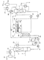
(第1の実施形態)図1は、第1の実施形態による二酸化炭素分離回収装置の概略構成図である。図1に示すように、二酸化炭素分離回収装置は、吸収塔1、プレート型の第1再生熱交換器5、シェルアンドチューブ型の第2再生熱交換器21、再生塔6、リボイラー8、リーン液タンク11、及びリーン液冷却器13を備えている。
(First Embodiment) FIG. 1 is a schematic configuration diagram of a carbon dioxide separation and recovery apparatus according to a first embodiment. As shown in FIG. 1, the carbon dioxide separation and recovery apparatus includes an absorption tower 1, a plate-type first
火力発電所等からの燃焼排ガス3は、燃焼排ガス供給口(図示せず)を介して吸収塔1の下部に導入される。吸収塔1では、燃焼排ガス3と吸収液とが接触し、燃焼排ガス3中の二酸化炭素が吸収液に吸収される。吸収液は、吸収塔1の上部から導入され、気液接触の効率を高めるための充填材が充填された充填層2を通過し、吸収塔1内を流下する。吸収液として、例えばアミン化合物と水との混合物を使用することができる。
燃焼排ガス3中の二酸化炭素の大部分は吸収液に吸収され、二酸化炭素含有量が減少した排ガスが吸収塔1の塔頂から排出される。吸収塔1から排出された排ガスは、吸収塔還流冷却器14により冷却されて水分が凝縮し、気液分離器15により水分と分離され、脱二酸化炭素ガス16が外部に排出される。気液分離機15で分離された水分は、吸収液成分を含んでいるため、吸収塔1に戻される。
Most of the carbon dioxide in the
吸収塔1の底部には、二酸化炭素を吸収した吸収液であるリッチ液が溜まる。吸収塔1の底部に溜まったリッチ液は、吸収塔1の底部から排出され、リッチ液移送ポンプ4により、第1再生熱交換器5及び第2再生熱交換器21を通過する。リッチ液は、第1再生熱交換器5及び第2再生熱交換器21において、再生塔6の底部から排出される高温のリーン液によって加熱される。加熱されたリッチ液は、再生塔6に供給される。
At the bottom of the absorption tower 1, a rich liquid that is an absorption liquid that has absorbed carbon dioxide is accumulated. The rich liquid accumulated at the bottom of the absorption tower 1 is discharged from the bottom of the absorption tower 1 and passes through the first
再生塔6に供給されたリッチ液は、気液接触の効率を高めるための充填材が充填された充填層7を通過し、再生塔6内を流下し、再生塔6の底部に溜まる。再生塔6の底部に溜まった吸収液は、その一部が再生塔6の底部から排出され、再生塔6とリボイラー8との間を循環する。吸収液は、リボイラー8において加熱媒体9により加熱され、蒸気と二酸化炭素ガスを発生する。発生した蒸気と二酸化炭素ガスは、再生塔6内に戻され、充填層7を通過して上昇し、流下する吸収液を加熱する。その結果、再生塔6に供給されたリッチ液から二酸化炭素ガスと水蒸気が放出され、再生塔6の底部には二酸化炭素ガスを放出した吸収液であるリーン液が溜まる。
The rich liquid supplied to the
吸収液から放出された二酸化炭素ガスと水蒸気を含む排ガスは、再生塔6の塔頂から排出される。再生塔6から排出された排ガスは、再生塔還流冷却器17により冷却されて水分が凝縮し、気液分離器18により水分と分離され、二酸化炭素ガス19が外部に排出される。一方、気液分離機18で分離された水分は、吸収液中の水分濃度を一定に保つため、再生塔6に戻される。
The exhaust gas containing carbon dioxide gas and water vapor released from the absorption liquid is discharged from the top of the
再生塔6の底部には、二酸化炭素溶存濃度が低下した吸収液であるリーン液が溜まっている。リーン液は再生塔6の底部から排出され、リーン液移送ポンプ10により、第2再生熱交換器21及び第1再生熱交換器5を順に通過する。このリーン液は、第2再生熱交換器21及び第1再生熱交換器5において、吸収塔1の底部から排出される低温のリッチ液を加熱する。第1再生熱交換器5を通過したリーン液は、リーン液タンク11内に貯留される。リーン液タンク11に貯留されたリーン液は、リーン液戻りポンプ12により、リーン液冷却器13を介して吸収塔1の上部に供給される。吸収塔1に供給されたリーン液は、燃焼排ガス3中の二酸化炭素の吸収に再利用される。
At the bottom of the
次に、第1再生熱交換器5及び第2再生熱交換器21について説明する。第1再生熱交換器5及び第2再生熱交換器21は、吸収塔1から再生塔6へと向かうリッチ液ラインと、再生塔6から吸収塔1へと向かうリーン液ラインが交差する地点に直列に配置されている。
Next, the first
第1再生熱交換器5はコンパクトなプレート型熱交換器である。再生塔6からのリーン液は、リボイラー8で加熱された際に得た余熱を有しているが、第2再生熱交換器21においてリッチ液を加熱した分だけ余熱が減少した状態で第1再生熱交換器5に供給される。第1再生熱交換器5では、リーン液の余熱でリッチ液を加熱する。リッチ液は、所定の圧力・温度を超えると、水蒸気及び二酸化炭素ガスを発生し始めるが、第1再生熱交換器5では、水蒸気及び二酸化炭素ガスが発生しない程度にリッチ液を加熱する。
The first
第1再生熱交換器で加熱されたリッチ液は、シェルアンドチューブ型熱交換器である第2再生熱交換器21のリッチ液入口24を介してシェル側に供給され、第2再生熱交換器21の下部に液相として溜まる。例えば、シェルアンドチューブ型熱交換器として、ケトルリボイラー型熱交換器を用いることができる。再生塔6からのリーン液は、リーン液入口27を介して第2再生熱交換器21のリーン液流路23に供給され、下部に溜まっているリッチ液を加熱する。これにより、リッチ液からは水蒸気及び二酸化炭素ガスが放出され、重力によって、ガスとガスを放出した後のセミリーン液とに分離される。リッチ液から放出されたガスは、シェル側上部のガス出口25から排出され、再生塔6に供給される。ガスを放出して二酸化炭素濃度が下がったリッチ液(セミリーン液)は、シェルの図中左側にある堰20を越えてセミリーン液出口26から排出される。このセミリーン液は、ポンプ22によって再生塔6に供給される。
The rich liquid heated in the first regenerative heat exchanger is supplied to the shell side via the rich
第2再生熱交換器21で余熱の一部を奪われたリーン液は、リーン液出口28から排出され、第1再生熱交換器5に供給され、吸収塔1からの低温リッチ液を加熱する。
The lean liquid from which part of the residual heat has been removed by the second
以上のように、本実施形態では、リッチ液は、プレート型の第1再生熱交換器5内を液相として流れ、シェルアンドチューブ型の第2再生熱交換器21において水蒸気と二酸化炭素ガスを放出する。第1再生熱交換器5では、液相のリッチ液だけをリーン液で加熱するので、機器をコンパクトにできる。また、偏流による伝熱性能劣化を抑制し、安定した運転を実現することができる。また、第2再生熱交換器21においてリッチ液からガスを放出することで、水蒸気発生や二酸化炭素ガス解離時の潜熱を利用することができ、リーン液からの回収熱量を増大させることができる。
As described above, in the present embodiment, the rich liquid flows as a liquid phase in the plate-type first
そのため、本実施形態によれば、再生熱交換器における回収熱量を増大させ、かつ再生熱交換器を含む二酸化炭素分離回収装置全体を安定的に運転することができる。また、再生塔6において吸収液から二酸化炭素を放散させるために必要なエネルギ投入量を削減することが可能となる。
Therefore, according to this embodiment, the amount of recovered heat in the regenerative heat exchanger can be increased, and the entire carbon dioxide separation and recovery device including the regenerative heat exchanger can be stably operated. In addition, it is possible to reduce the amount of energy input required to dissipate carbon dioxide from the absorbing solution in the
なお、第2再生熱交換器21では、リッチ液が加熱されて水蒸気及び二酸化炭素ガスが発生し、気液二相流になる。ガスの滞留等を考慮すると、この気液二相流は、下降流よりも、上昇流又は水平流にすることが好ましい。
In the second
また、上記第1の実施形態では、第2再生熱交換器21として、シェルアンドチューブ型熱交換器を用いる例について説明したが、二重管式熱交換器、容器にコイル状チューブを浸漬したジャケット型、渦板型などの熱交換器を使用することも可能である。更にチューブ自体も、外表面や内表面にフィン等の加工を施したものを使用することが可能である。
Moreover, in the said 1st Embodiment, although the example using a shell and tube type heat exchanger was demonstrated as the 2nd reproduction |
(第2の実施形態)図2は、第2の実施形態による二酸化炭素分離回収装置の概略構成図である。本実施形態による二酸化炭素分離回収装置は、図1に示す第1の実施形態と比較して、シェルアンドチューブ型熱交換器である第2再生熱交換器21のチューブ側にリッチ液を供給する点で相違する。
(Second Embodiment) FIG. 2 is a schematic configuration diagram of a carbon dioxide separation and recovery apparatus according to a second embodiment. Compared with the first embodiment shown in FIG. 1, the carbon dioxide separation and recovery apparatus according to this embodiment supplies a rich liquid to the tube side of the second
第1再生熱交換器5で加熱された液相のリッチ液は、リッチ液入口24を介して第2再生熱交換器21に供給される。また、再生塔6からの高温リーン液が、リーン液入口27を介して、第2再生熱交換器21のシェル側に供給される。
The liquid rich liquid heated in the first
第2再生熱交換器21においてリッチ液を加熱することで、水蒸気及び二酸化炭素ガスが発生する。リッチ液は気液二相の状態で水平に流れ、図中右側の水室で重力によって気液分離され、ガスはガス出口25を介して排出され、再生塔6の上部に供給される。一方、液体はセミリーン液出口26を介して排出され、ポンプ22によって再生塔6の上部に供給される。リーン液はシェル側を流れてリッチ液を加熱した後、リーン液出口28から排出され、再生熱交換器5に供給される。
Steam and carbon dioxide gas are generated by heating the rich liquid in the second
このような構成によっても、上記第1の実施形態と同様に、第1再生熱交換器5では、液相のリッチ液だけをリーン液で加熱するので、機器をコンパクトにできる。また、偏流による伝熱性能劣化を抑制し、安定した運転を実現することができる。また、第2再生熱交換器21においてリッチ液からガスを放出することで、水蒸気発生や二酸化炭素ガス解離時の潜熱を利用することができ、リーン液からの回収熱量を増大させることができる。
Even with such a configuration, as in the first embodiment, the first
(第3実施形態)図3は、第3の実施形態による二酸化炭素分離回収装置の概略構成図である。本実施形態による二酸化炭素分離回収装置は、図1に示す第1の実施形態と比較して、シェルアンドチューブ型熱交換器である第2再生熱交換器21を垂直設置し、チューブ側にリッチ液を下向きに流す流下液膜型とする点で相違する。
(Third Embodiment) FIG. 3 is a schematic configuration diagram of a carbon dioxide separation and recovery apparatus according to a third embodiment. Compared with the first embodiment shown in FIG. 1, the carbon dioxide separation and recovery apparatus according to this embodiment has a second
第2再生熱交換器21のチューブ側頂部のリッチ液入口24を介してリッチ液が供給される。この場合、供給口の上流側に減圧弁等を設けてリッチ液を減圧し、多量のガスを発生させてチューブ内を下降する液量を減らすことが好ましい。これによって、チューブ壁面に薄い液膜を形成させ、中心部にガスが通り抜ける空間を確保する。液膜はシェル側を流れる再生塔6からの高温リーン液で加熱され、さらにガスを発生しながら落下する。発生したガスは中心部の空間を上方に向かって流れる。
The rich liquid is supplied through the rich
ガスは、チューブ側頂部のガス出口25から排出され、再生塔6に供給される。また、第2再生熱交換器21の底部のセミリーン液出口26から排出されるセミリーン液は、ポンプ22によって再生塔6の上部に供給される。
The gas is discharged from the
このような構成によっても、上記第1の実施形態と同様に、第1再生熱交換器5では、液相のリッチ液だけをリーン液で加熱するので、機器をコンパクトにできる。また、偏流による伝熱性能劣化を抑制し、安定した運転を実現することができる。また、第2再生熱交換器21においてリッチ液からガスを放出することで、水蒸気発生や二酸化炭素ガス解離時の潜熱を利用することができ、リーン液からの回収熱量を増大させることができる。
Even with such a configuration, as in the first embodiment, the first
(第4の実施形態)図4は、第4の実施形態による二酸化炭素分離回収装置の概略構成図である。本実施形態による二酸化炭素分離回収装置は、図1に示す第1の実施形態と比較して、シェルアンドチューブ型熱交換器である第2再生熱交換器21を垂直設置し、チューブ側にリッチ液を上向きに流す点で相違する。
(Fourth Embodiment) FIG. 4 is a schematic configuration diagram of a carbon dioxide separation and recovery apparatus according to a fourth embodiment. Compared with the first embodiment shown in FIG. 1, the carbon dioxide separation and recovery apparatus according to this embodiment has a second
第2再生熱交換器21のチューブ側底部のリッチ液入口24を介してリッチ液が供給される。再生塔6からの高温リーン液は、シェル側上部のリーン液入口27を介して第2再生熱交換器21に供給され、シェル側を下部に流れてリーン液出口28から排出される。チューブ側を上昇するリッチ液は、高温リーン液によって加熱され、ガスを発生する。リッチ液は、第2再生熱交換器21の頂部においてガスとセミリーン液とに分離し、ガスはガス出口25から排出され、セミリーン液はセミリーン液出口26から排出される。排出されたガスは再生塔6の上部に供給される。また、排出されたセミリーン液は、ポンプ22によって再生塔6の上部に供給される。
The rich liquid is supplied through the rich
このような構成によっても、上記第1の実施形態と同様に、第1再生熱交換器5では、液相のリッチ液だけをリーン液で加熱するので、機器をコンパクトにできる。また、偏流による伝熱性能劣化を抑制し、安定した運転を実現することができる。また、第2再生熱交換器21においてリッチ液からガスを放出することで、水蒸気発生や二酸化炭素ガス解離時の潜熱を利用することができ、リーン液からの回収熱量を増大させることができる。
Even with such a configuration, as in the first embodiment, the first
(第5の実施形態)図5は、第5の実施形態による二酸化炭素分離回収装置の概略構成図である。本実施形態による二酸化炭素分離回収装置は、図1に示す第1の実施形態と比較して、シェルアンドチューブ型熱交換器である第2再生熱交換器21を垂直設置し、シェル側にリッチ液を上向きに流す点で相違する。
(Fifth Embodiment) FIG. 5 is a schematic configuration diagram of a carbon dioxide separation and recovery apparatus according to a fifth embodiment. Compared with the first embodiment shown in FIG. 1, the carbon dioxide separation and recovery apparatus according to the present embodiment has a second
第2再生熱交換器21のシェル側下部のリッチ液入口24を介してリッチ液が供給される。また、再生塔6からの高温リーン液は、第2再生熱交換器21のチューブ側上部のリーン液入口27から供給され、底部のリーン液出口28に向かって下降して流れる。このとき、リッチ液は高温リーン液により加熱され、ガスを発生しながら上昇してシェル側上部のノズルから気液二相の状態で排出される。気液二相のリッチ液は、気液分離器29によりガスと液体とに分離され、ガスは再生塔6の上部に供給される。また、液体(セミリーン液)は、ポンプ22によって再生塔6の上部に供給される。
The rich liquid is supplied through the rich
なお、気液分離器29を省略し、シェル側上部のノズルから、気液二相のリッチ液を再生塔6の上部に直接供給するようにしても良い。
Note that the gas-
このような構成によっても、上記第1の実施形態と同様に、第1再生熱交換器5では、液相のリッチ液だけをリーン液で加熱するので、機器をコンパクトにできる。また、偏流による伝熱性能劣化を抑制し、安定した運転を実現することができる。また、第2再生熱交換器21においてリッチ液からガスを放出することで、水蒸気発生や二酸化炭素ガス解離時の潜熱を利用することができ、リーン液からの回収熱量を増大させることができる。
Even with such a configuration, as in the first embodiment, the first
(第6の実施形態)図6は、第6の実施形態による二酸化炭素分離回収装置の概略構成図である。本実施形態による二酸化炭素分離回収装置は、図1に示す第1の実施形態と比較して、第2再生熱交換器21に供給されるリッチ液の状態を監視する点で相違する。
(Sixth Embodiment) FIG. 6 is a schematic configuration diagram of a carbon dioxide separation and recovery apparatus according to a sixth embodiment. The carbon dioxide separation and recovery apparatus according to the present embodiment is different from the first embodiment shown in FIG. 1 in that the state of the rich liquid supplied to the second
図6に示すように、第1再生熱交換器5と第2再生熱交換器21のリッチ液入口24との間のリッチ液ラインに、圧力調整バルブ30、リッチ液温度測定器32、及びリッチ液圧力測定器33が設けられている。圧力調整バルブ30によりリッチ液の圧力が調整される。リッチ液温度測定器32及びリッチ液圧力測定器33は、第1再生熱交換器5から排出された(第2再生熱交換器21に供給される)リッチ液の温度及び圧力を測定し、測定結果を制御装置34に通知する。
As shown in FIG. 6, a
また、吸収塔1の底部にある液溜部から第1再生熱交換器5の入口部との間のリッチ液ラインに、リッチ液溶存二酸化炭素濃度測定器31が設けられている。リッチ液溶存二酸化炭素濃度測定器31は、吸収塔1から排出された(第1再生熱交換器5に供給される)リッチ液の溶存二酸化炭素濃度を測定し、測定結果を制御装置34に通知する。
Further, a rich liquid dissolved carbon dioxide
制御装置34は、二酸化炭素分離回収装置で使用されている吸収液の気液平衡データを用いて、リッチ液溶存二酸化炭素濃度測定器31、リッチ液温度測定器32から得られる測定値を基に、第1再生熱交換器5内でリッチ液がガスを発生する直前の液相状態を保ち続けることができる圧力値を算出する。そして、制御装置34は、第1再生熱交換器5の出口圧力、即ちリッチ液圧力測定器33の測定値が、算出した圧力値以上となるように、調整バルブ30を制御する。
Based on the measurement values obtained from the rich liquid dissolved carbon dioxide
これにより、リッチ液は、第1再生熱交換器5では液相、第2再生熱交換器21では気液二相という状態を安定して保ちながら運転を継続することができる。
As a result, the rich liquid can continue to operate while stably maintaining the liquid phase in the first
また、本実施形態によれば、上記第1の実施形態と同様に、第1再生熱交換器5では、液相のリッチ液だけをリーン液で加熱するので、機器をコンパクトにできる。また、偏流による伝熱性能劣化を抑制し、安定した運転を実現することができる。また、第2再生熱交換器21においてリッチ液からガスを放出することで、水蒸気発生や二酸化炭素ガス解離時の潜熱を利用することができ、リーン液からの回収熱量を増大させることができる。
Further, according to the present embodiment, as in the first embodiment, the first
(第7の実施形態)図7は、第7の実施形態による二酸化炭素分離回収装置の概略構成図である。本実施形態による二酸化炭素分離回収装置は、図1に示す第1の実施形態と比較して、吸収塔1から排出されたリッチ液を分流し、一方を第1再生熱交換器5へ供給し、他方を二酸化炭素発生器36に供給する点で異なる。
(Seventh Embodiment) FIG. 7 is a schematic configuration diagram of a carbon dioxide separation and recovery apparatus according to a seventh embodiment. Compared with the first embodiment shown in FIG. 1, the carbon dioxide separation and recovery apparatus according to the present embodiment diverts the rich liquid discharged from the absorption tower 1 and supplies one to the first
図7に示すように、吸収塔1から排出されたリッチ液は、分流装置35で第1リッチ液R1と第2リッチ液R2とに分流される。第1リッチ液R1は第1再生熱交換器5に供給され、リーン液と熱交換し、加熱される。第1リッチ液R1は液相の状態で第1再生熱交換器5から排出され、第2再生熱交換器21においてさらに加熱され、気液二相となる。
As shown in FIG. 7, the rich liquid discharged from the absorption tower 1 is diverted into the first rich liquid R1 and the second rich liquid R2 by the
第2リッチ液R2は、二酸化炭素発生器36に供給される。二酸化炭素発生器(熱交換器)36は、再生塔6の頂部から排出される高温のガスを用いて第2リッチ液R2を加熱する。これにより、再生塔6の頂部から排出されるガスが保有する熱を、第2リッチ液R2に回収できるので、リボイラー8に投入するエネルギ量をさらに削減することができる。
The second rich liquid R2 is supplied to the
また、本実施形態によれば、上記第1の実施形態と同様に、第1再生熱交換器5では、液相のリッチ液だけをリーン液で加熱するので、機器をコンパクトにできる。また、偏流による伝熱性能劣化を抑制し、安定した運転を実現することができる。また、第2再生熱交換器21においてリッチ液からガスを放出することで、水蒸気発生や二酸化炭素ガス解離時の潜熱を利用することができ、リーン液からの回収熱量を増大させることができる。
Further, according to the present embodiment, as in the first embodiment, the first
なお、本実施形態において、二酸化炭素発生器36を省略し、第2リッチ液R2を再生塔6の頂部付近に直接供給し、再生塔6の内部で高温のガスと接触させても、同様の効果を得ることができる。
In the present embodiment, the
以上説明した少なくともひとつの実施形態によれば、再生熱交換器における回収熱量を増大させ、かつ二酸化炭素分離回収装置を安定的に運転することができる。 According to at least one embodiment described above, the amount of recovered heat in the regenerative heat exchanger can be increased, and the carbon dioxide separation and recovery apparatus can be operated stably.
本発明のいくつかの実施形態を説明したが、これらの実施形態は、例として提示したものであり、発明の範囲を限定することは意図していない。これら新規な実施形態は、その他の様々な形態で実施されることが可能であり、発明の要旨を逸脱しない範囲で、種々の省略、置き換え、変更を行うことができる。これら実施形態やその変形は、発明の範囲や要旨に含まれるとともに、特許請求の範囲に記載された発明とその均等の範囲に含まれる。 Although several embodiments of the present invention have been described, these embodiments are presented by way of example and are not intended to limit the scope of the invention. These novel embodiments can be implemented in various other forms, and various omissions, replacements, and changes can be made without departing from the scope of the invention. These embodiments and modifications thereof are included in the scope and gist of the invention, and are included in the invention described in the claims and the equivalents thereof.
1 吸収塔
5 第1再生熱交換器
6 再生塔
8 リボイラー
21 第2再生熱交換器
DESCRIPTION OF SYMBOLS 1
Claims (4)
吸収液を加熱して、前記吸収液から二酸化炭素を含むガスを放出させ、前記リッチ液よりも二酸化炭素濃度の低いリーン液を排出する再生塔と、
前記リーン液を用いて前記リッチ液を加熱する第1再生熱交換器及び第2再生熱交換器と、
を備え、
前記第1再生熱交換器は、プレート型熱交換器であり、前記吸収塔から排出された前記リッチ液を、前記第2再生熱交換器から排出された前記リーン液を用いて加熱し、液相のリッチ液を排出し、
前記第2再生熱交換器は、シェルアンドチューブ型熱交換器であり、前記第1再生熱交換器から排出された液相の前記リッチ液を、前記再生塔から排出された前記リーン液を用いて加熱し、前記リッチ液から水蒸気及び二酸化炭素ガスを発生させ、
前記第1再生熱交換器から排出された前記リーン液が前記吸収塔に供給され、
前記第2再生熱交換器から排出された前記リッチ液、前記水蒸気及び二酸化炭素ガスが前記再生塔に供給され、
前記第1再生熱交換器に供給されるリッチ液の二酸化炭素濃度を測定する第1測定器と、
前記第1再生熱交換器から排出されるリッチ液の温度を測定する第2測定器と、
前記第1再生熱交換器から排出されるリッチ液の圧力を測定する第3測定器と、
前記第1再生熱交換器から排出されるリッチ液の圧力を調整する圧力調整バルブと、
前記第1測定器及び前記第2測定器を用いて前記第1再生熱交換器から排出されるリッチ液が液相状態を保つ圧力値を算出し、前記第3測定器の測定結果が算出した圧力値以上となるように前記圧力調整バルブを制御する制御装置と、
をさらに備えることを特徴とする二酸化炭素分離回収装置。 An absorption tower that introduces a carbon dioxide-containing gas, contacts an absorption liquid that absorbs carbon dioxide, and discharges a rich liquid that has absorbed carbon dioxide;
A regenerating tower that heats the absorbing liquid, releases a gas containing carbon dioxide from the absorbing liquid, and discharges a lean liquid having a lower carbon dioxide concentration than the rich liquid;
A first regenerative heat exchanger and a second regenerative heat exchanger that heat the rich liquid using the lean liquid;
With
The first regenerative heat exchanger is a plate heat exchanger, and the rich liquid discharged from the absorption tower is heated using the lean liquid discharged from the second regenerative heat exchanger, Drain the rich liquid of the phase,
The second regenerative heat exchanger is a shell-and-tube heat exchanger, and the rich liquid in the liquid phase discharged from the first regenerative heat exchanger is used as the lean liquid discharged from the regeneration tower. To generate water vapor and carbon dioxide gas from the rich liquid,
The lean liquid discharged from the first regenerative heat exchanger is supplied to the absorption tower;
The rich liquid discharged from the second regeneration heat exchanger, the water vapor and carbon dioxide gas are supplied to the regeneration tower ;
A first measuring device for measuring the carbon dioxide concentration of the rich liquid supplied to the first regenerative heat exchanger;
A second measuring device for measuring the temperature of the rich liquid discharged from the first regenerative heat exchanger;
A third measuring device for measuring the pressure of the rich liquid discharged from the first regenerative heat exchanger;
A pressure adjusting valve for adjusting the pressure of the rich liquid discharged from the first regenerative heat exchanger;
Using the first measuring device and the second measuring device, a pressure value for maintaining the liquid phase state of the rich liquid discharged from the first regenerative heat exchanger was calculated, and the measurement result of the third measuring device was calculated. A control device for controlling the pressure regulating valve so as to be equal to or higher than a pressure value;
A carbon dioxide separation and recovery device , further comprising:
前記第1リッチ液は前記第1再生熱交換器に供給され、
前記第2リッチ液は、前記再生塔から排出される前記二酸化炭素を含むガスにより加熱されることを特徴とする請求項1に記載の二酸化炭素分離回収装置。 A diversion device for diverting the rich liquid discharged from the absorption tower into the first rich liquid and the second rich liquid;
The first rich liquid is supplied to the first regenerative heat exchanger;
The carbon dioxide separation and recovery apparatus according to claim 1, wherein the second rich liquid is heated by a gas containing the carbon dioxide discharged from the regeneration tower.
前記吸収塔において、二酸化炭素含有ガスと前記第1再生熱交換器から排出されたリーン液とを接触させ、二酸化炭素を吸収したリッチ液を前記吸収塔から排出し、
前記第1再生熱交換器において、前記吸収塔から排出された前記リッチ液を、前記第2再生熱交換器から排出されたリーン液を用いて加熱し、液相のリッチ液を排出し、
前記第2再生熱交換器において、前記第1再生熱交換器から排出された液相の前記リッチ液を、前記再生塔から排出されたリーン液を用いて加熱し、前記リッチ液から水蒸気及び二酸化炭素ガスを発生させ、
前記第2再生熱交換器から排出された前記リッチ液、前記水蒸気及び二酸化炭素ガスを前記再生塔に供給し、前記リッチ液から二酸化炭素を含むガスを放出させ、前記リッチ液よりも二酸化炭素濃度の低い前記リーン液を排出し、
前記第1再生熱交換器に供給されるリッチ液の二酸化炭素濃度を第1測定器により測定し、
前記第1再生熱交換器から排出されるリッチ液の温度を第2測定器により測定し、
前記第1再生熱交換器から排出されるリッチ液の圧力を第3測定器により測定し、
前記第1再生熱交換器から排出されるリッチ液の圧力を圧力調整バルブにより調整し、
制御装置が、前記第1測定器及び前記第2測定器を用いて前記第1再生熱交換器から排出されるリッチ液が液相状態を保つ圧力値を算出し、前記第3測定器の測定結果が算出した圧力値以上となるように前記圧力調整バルブを制御することを特徴とする二酸化炭素分離回収装置の運転方法。 An operation method of a carbon dioxide separation and recovery device comprising an absorption tower, a regeneration tower, a plate-type first regeneration heat exchanger, and a shell-and-tube second regeneration heat exchanger,
In the absorption tower, the carbon dioxide-containing gas is brought into contact with the lean liquid discharged from the first regeneration heat exchanger, and the rich liquid that has absorbed carbon dioxide is discharged from the absorption tower.
In the first regenerative heat exchanger, the rich liquid discharged from the absorption tower is heated using the lean liquid discharged from the second regenerative heat exchanger, and a liquid rich liquid is discharged,
In the second regenerative heat exchanger, the rich liquid in the liquid phase discharged from the first regenerative heat exchanger is heated using the lean liquid discharged from the regeneration tower, and water vapor and carbon dioxide are discharged from the rich liquid. Generate carbon gas,
The rich liquid discharged from the second regenerative heat exchanger, the water vapor and carbon dioxide gas are supplied to the regeneration tower, a gas containing carbon dioxide is released from the rich liquid, and the carbon dioxide concentration is higher than that of the rich liquid. the lean solution discharged low,
The carbon dioxide concentration of the rich liquid supplied to the first regenerative heat exchanger is measured by the first measuring device,
Measuring the temperature of the rich liquid discharged from the first regenerative heat exchanger with a second measuring device;
Measuring the pressure of the rich liquid discharged from the first regenerative heat exchanger with a third measuring instrument;
Adjusting the pressure of the rich liquid discharged from the first regenerative heat exchanger by a pressure adjusting valve;
The control device uses the first measuring device and the second measuring device to calculate a pressure value at which the rich liquid discharged from the first regenerative heat exchanger maintains a liquid phase state, and the measurement by the third measuring device A method for operating a carbon dioxide separation and recovery device , wherein the pressure control valve is controlled so that a result is equal to or greater than a calculated pressure value .
Priority Applications (5)
| Application Number | Priority Date | Filing Date | Title |
|---|---|---|---|
| JP2013106435A JP6157925B2 (en) | 2013-05-20 | 2013-05-20 | Carbon dioxide separation and recovery device and operation method thereof |
| US14/163,268 US9248397B2 (en) | 2013-05-20 | 2014-01-24 | Carbon dioxide separating and capturing apparatus and method of operating same |
| EP14152866.1A EP2805757B1 (en) | 2013-05-20 | 2014-01-28 | Carbon dioxide separating and capturing apparatus and method of operating the same |
| AU2014200565A AU2014200565B2 (en) | 2013-05-20 | 2014-01-31 | Carbon dioxide separating and capturing apparatus and method of operating same |
| CN201410059738.5A CN104174257B (en) | 2013-05-20 | 2014-02-21 | Carbon dioxide separation and acquisition equipment and method of operating thereof |
Applications Claiming Priority (1)
| Application Number | Priority Date | Filing Date | Title |
|---|---|---|---|
| JP2013106435A JP6157925B2 (en) | 2013-05-20 | 2013-05-20 | Carbon dioxide separation and recovery device and operation method thereof |
Publications (2)
| Publication Number | Publication Date |
|---|---|
| JP2014226583A JP2014226583A (en) | 2014-12-08 |
| JP6157925B2 true JP6157925B2 (en) | 2017-07-05 |
Family
ID=49999843
Family Applications (1)
| Application Number | Title | Priority Date | Filing Date |
|---|---|---|---|
| JP2013106435A Expired - Fee Related JP6157925B2 (en) | 2013-05-20 | 2013-05-20 | Carbon dioxide separation and recovery device and operation method thereof |
Country Status (5)
| Country | Link |
|---|---|
| US (1) | US9248397B2 (en) |
| EP (1) | EP2805757B1 (en) |
| JP (1) | JP6157925B2 (en) |
| CN (1) | CN104174257B (en) |
| AU (1) | AU2014200565B2 (en) |
Families Citing this family (12)
| Publication number | Priority date | Publication date | Assignee | Title |
|---|---|---|---|---|
| KR101421611B1 (en) * | 2013-06-04 | 2014-07-22 | 한국전력기술 주식회사 | Apparatus for separating CO2 having sensible heat recovery using decompression and phase separation |
| KR101550618B1 (en) * | 2014-01-14 | 2015-09-07 | 현대자동차 주식회사 | Reboiling device and regeneration tower |
| KR101646125B1 (en) * | 2015-02-16 | 2016-08-12 | 현대자동차 주식회사 | Gas capturing plant |
| CN106731600A (en) * | 2016-12-20 | 2017-05-31 | 新疆敦华石油技术股份有限公司 | A kind of collecting carbonic anhydride liquefying plant |
| CN106914104B (en) * | 2017-04-18 | 2022-08-12 | 长沙紫宸科技开发有限公司 | Absorption-regenerator suitable for continuously capturing carbon dioxide in flue gas |
| CN107243258A (en) * | 2017-07-20 | 2017-10-13 | 中国华能集团清洁能源技术研究院有限公司 | The regenerating unit and method of sour gas trapping solution in a kind of power-plant flue gas |
| CN108801036A (en) * | 2018-06-22 | 2018-11-13 | 沈阳汇博热能设备有限公司 | A kind of kettle type reboiler tube bank limiting device |
| CN114632402B (en) * | 2020-12-16 | 2022-11-11 | 中冶京诚工程技术有限公司 | Trapping method of flue gas carbon dioxide trapping system |
| CN113828120A (en) * | 2021-11-01 | 2021-12-24 | 中国船舶重工集团公司第七一一研究所 | Low-energy-consumption marine diesel engine flue gas CO2Trapping system |
| CN114272735B (en) * | 2021-12-27 | 2022-11-25 | 北京华源泰盟节能设备有限公司 | Flue gas waste heat utilization and carbon capture integrated system |
| CN114712990B (en) * | 2022-03-17 | 2023-08-08 | 中国华能集团清洁能源技术研究院有限公司 | CO (carbon monoxide) 2 Regeneration device and process method |
| CN115212710A (en) * | 2022-07-22 | 2022-10-21 | 碳索(杭州)能源环境科技有限公司 | Is suitable for ultralow-concentration CO 2 Carbon capture system of flue gas |
Family Cites Families (10)
| Publication number | Priority date | Publication date | Assignee | Title |
|---|---|---|---|---|
| JP2882950B2 (en) * | 1992-09-16 | 1999-04-19 | 関西電力株式会社 | Method for removing carbon dioxide in flue gas |
| JP4274846B2 (en) | 2003-04-30 | 2009-06-10 | 三菱重工業株式会社 | Carbon dioxide recovery method and system |
| JP4690659B2 (en) | 2004-03-15 | 2011-06-01 | 三菱重工業株式会社 | CO2 recovery device |
| DE102005040531A1 (en) | 2005-08-26 | 2007-03-22 | Siemens Ag | Power source, control device and method for operating the control device |
| JP2010201379A (en) * | 2009-03-04 | 2010-09-16 | Toshiba Corp | Carbon dioxide recovery system |
| JP5383338B2 (en) * | 2009-06-17 | 2014-01-08 | 三菱重工業株式会社 | CO2 recovery device and CO2 recovery method |
| JP5697411B2 (en) | 2010-11-17 | 2015-04-08 | 株式会社東芝 | Carbon dioxide recovery device and carbon dioxide recovery method |
| US8845790B2 (en) * | 2011-01-06 | 2014-09-30 | Alstom Technology Ltd | Method and system for removal of gaseous contaminants |
| JP5658101B2 (en) * | 2011-07-06 | 2015-01-21 | Jfeスチール株式会社 | CO2 recovery device and recovery method |
| EP2570164B1 (en) | 2011-09-16 | 2013-10-23 | MT-Biomethan GmbH | Device and method for removing carbon dioxide from biogas by means of absorption |
-
2013
- 2013-05-20 JP JP2013106435A patent/JP6157925B2/en not_active Expired - Fee Related
-
2014
- 2014-01-24 US US14/163,268 patent/US9248397B2/en not_active Expired - Fee Related
- 2014-01-28 EP EP14152866.1A patent/EP2805757B1/en not_active Not-in-force
- 2014-01-31 AU AU2014200565A patent/AU2014200565B2/en not_active Ceased
- 2014-02-21 CN CN201410059738.5A patent/CN104174257B/en not_active Expired - Fee Related
Also Published As
| Publication number | Publication date |
|---|---|
| EP2805757B1 (en) | 2015-12-02 |
| CN104174257B (en) | 2016-09-07 |
| AU2014200565B2 (en) | 2015-10-01 |
| JP2014226583A (en) | 2014-12-08 |
| CN104174257A (en) | 2014-12-03 |
| US9248397B2 (en) | 2016-02-02 |
| AU2014200565A1 (en) | 2014-12-04 |
| EP2805757A1 (en) | 2014-11-26 |
| US20140338394A1 (en) | 2014-11-20 |
Similar Documents
| Publication | Publication Date | Title |
|---|---|---|
| JP6157925B2 (en) | Carbon dioxide separation and recovery device and operation method thereof | |
| JP5582960B2 (en) | Carbon dioxide separation and recovery system and reboiler heat input measurement method | |
| JP5331587B2 (en) | Carbon dioxide recovery system | |
| JP5767609B2 (en) | Carbon dioxide recovery device and operation method thereof | |
| JP5659176B2 (en) | Carbon dioxide recovery device and carbon dioxide recovery method | |
| JP5349221B2 (en) | Carbon dioxide recovery device | |
| JP5741690B2 (en) | Carbon dioxide recovery method and recovery apparatus | |
| JP6180793B2 (en) | Carbon dioxide recovery device and carbon dioxide recovery method | |
| JP2010201379A (en) | Carbon dioxide recovery system | |
| JP5586358B2 (en) | Carbon dioxide separation and recovery system and operation method thereof | |
| JP5646524B2 (en) | Carbon dioxide separation and recovery system and operation method thereof | |
| JP6560938B2 (en) | Absorption tower with absorption reaction separator | |
| JP5720463B2 (en) | Carbon dioxide recovery method and recovery apparatus | |
| JP2019103973A (en) | Carbon dioxide recovery system and operation method thereof | |
| JP2011125824A (en) | System for separating/recovering carbon dioxide | |
| JP6225574B2 (en) | Carbon dioxide recovery method and recovery apparatus | |
| JP2019118902A (en) | Carbon dioxide recovery system and method for operation thereof | |
| JP6618840B2 (en) | Carbon dioxide recovery system and carbon dioxide recovery method | |
| JP2015097986A (en) | Distillation column, liquid heating method, and carbon dioxide recovery apparatus and carbon dioxide recovery method using the same |
Legal Events
| Date | Code | Title | Description |
|---|---|---|---|
| A621 | Written request for application examination |
Free format text: JAPANESE INTERMEDIATE CODE: A621 Effective date: 20160212 |
|
| A977 | Report on retrieval |
Free format text: JAPANESE INTERMEDIATE CODE: A971007 Effective date: 20170323 |
|
| A131 | Notification of reasons for refusal |
Free format text: JAPANESE INTERMEDIATE CODE: A131 Effective date: 20170328 |
|
| A521 | Written amendment |
Free format text: JAPANESE INTERMEDIATE CODE: A523 Effective date: 20170414 |
|
| TRDD | Decision of grant or rejection written | ||
| A01 | Written decision to grant a patent or to grant a registration (utility model) |
Free format text: JAPANESE INTERMEDIATE CODE: A01 Effective date: 20170509 |
|
| A61 | First payment of annual fees (during grant procedure) |
Free format text: JAPANESE INTERMEDIATE CODE: A61 Effective date: 20170607 |
|
| R151 | Written notification of patent or utility model registration |
Ref document number: 6157925 Country of ref document: JP Free format text: JAPANESE INTERMEDIATE CODE: R151 |
|
| LAPS | Cancellation because of no payment of annual fees |