JP5582960B2 - Carbon dioxide separation and recovery system and reboiler heat input measurement method - Google Patents
Carbon dioxide separation and recovery system and reboiler heat input measurement method Download PDFInfo
- Publication number
- JP5582960B2 JP5582960B2 JP2010237307A JP2010237307A JP5582960B2 JP 5582960 B2 JP5582960 B2 JP 5582960B2 JP 2010237307 A JP2010237307 A JP 2010237307A JP 2010237307 A JP2010237307 A JP 2010237307A JP 5582960 B2 JP5582960 B2 JP 5582960B2
- Authority
- JP
- Japan
- Prior art keywords
- heat
- heating medium
- liquid
- supplied
- reboiler
- Prior art date
- Legal status (The legal status is an assumption and is not a legal conclusion. Google has not performed a legal analysis and makes no representation as to the accuracy of the status listed.)
- Active
Links
Images

Classifications
-
- F—MECHANICAL ENGINEERING; LIGHTING; HEATING; WEAPONS; BLASTING
- F01—MACHINES OR ENGINES IN GENERAL; ENGINE PLANTS IN GENERAL; STEAM ENGINES
- F01K—STEAM ENGINE PLANTS; STEAM ACCUMULATORS; ENGINE PLANTS NOT OTHERWISE PROVIDED FOR; ENGINES USING SPECIAL WORKING FLUIDS OR CYCLES
- F01K13/00—General layout or general methods of operation of complete plants
-
- B—PERFORMING OPERATIONS; TRANSPORTING
- B01—PHYSICAL OR CHEMICAL PROCESSES OR APPARATUS IN GENERAL
- B01D—SEPARATION
- B01D53/00—Separation of gases or vapours; Recovering vapours of volatile solvents from gases; Chemical or biological purification of waste gases, e.g. engine exhaust gases, smoke, fumes, flue gases, aerosols
- B01D53/14—Separation of gases or vapours; Recovering vapours of volatile solvents from gases; Chemical or biological purification of waste gases, e.g. engine exhaust gases, smoke, fumes, flue gases, aerosols by absorption
- B01D53/1425—Regeneration of liquid absorbents
-
- B—PERFORMING OPERATIONS; TRANSPORTING
- B01—PHYSICAL OR CHEMICAL PROCESSES OR APPARATUS IN GENERAL
- B01D—SEPARATION
- B01D53/00—Separation of gases or vapours; Recovering vapours of volatile solvents from gases; Chemical or biological purification of waste gases, e.g. engine exhaust gases, smoke, fumes, flue gases, aerosols
- B01D53/14—Separation of gases or vapours; Recovering vapours of volatile solvents from gases; Chemical or biological purification of waste gases, e.g. engine exhaust gases, smoke, fumes, flue gases, aerosols by absorption
- B01D53/1456—Removing acid components
- B01D53/1475—Removing carbon dioxide
-
- B—PERFORMING OPERATIONS; TRANSPORTING
- B01—PHYSICAL OR CHEMICAL PROCESSES OR APPARATUS IN GENERAL
- B01D—SEPARATION
- B01D2252/00—Absorbents, i.e. solvents and liquid materials for gas absorption
- B01D2252/10—Inorganic absorbents
- B01D2252/103—Water
-
- B—PERFORMING OPERATIONS; TRANSPORTING
- B01—PHYSICAL OR CHEMICAL PROCESSES OR APPARATUS IN GENERAL
- B01D—SEPARATION
- B01D2252/00—Absorbents, i.e. solvents and liquid materials for gas absorption
- B01D2252/20—Organic absorbents
- B01D2252/204—Amines
-
- B—PERFORMING OPERATIONS; TRANSPORTING
- B01—PHYSICAL OR CHEMICAL PROCESSES OR APPARATUS IN GENERAL
- B01D—SEPARATION
- B01D2258/00—Sources of waste gases
- B01D2258/02—Other waste gases
- B01D2258/0283—Flue gases
-
- B—PERFORMING OPERATIONS; TRANSPORTING
- B01—PHYSICAL OR CHEMICAL PROCESSES OR APPARATUS IN GENERAL
- B01D—SEPARATION
- B01D2259/00—Type of treatment
- B01D2259/65—Employing advanced heat integration, e.g. Pinch technology
-
- Y—GENERAL TAGGING OF NEW TECHNOLOGICAL DEVELOPMENTS; GENERAL TAGGING OF CROSS-SECTIONAL TECHNOLOGIES SPANNING OVER SEVERAL SECTIONS OF THE IPC; TECHNICAL SUBJECTS COVERED BY FORMER USPC CROSS-REFERENCE ART COLLECTIONS [XRACs] AND DIGESTS
- Y02—TECHNOLOGIES OR APPLICATIONS FOR MITIGATION OR ADAPTATION AGAINST CLIMATE CHANGE
- Y02C—CAPTURE, STORAGE, SEQUESTRATION OR DISPOSAL OF GREENHOUSE GASES [GHG]
- Y02C20/00—Capture or disposal of greenhouse gases
- Y02C20/40—Capture or disposal of greenhouse gases of CO2
Description
本発明は、二酸化炭素分離回収システム及びリボイラー入熱量測定方法に関する。 The present invention relates to a carbon dioxide separation and recovery system and a reboiler heat input measuring method.
近年、大量の化石燃料を使用する火力発電所等を対象に、燃焼排ガスとアミン系吸収液を接触させ、燃焼排ガス中の二酸化炭素を分離回収する方法、及び回収された二酸化炭素を大気へ放出することなく貯蔵する方法が研究されている。 In recent years, for thermal power plants that use large amounts of fossil fuels, a method for separating and recovering carbon dioxide in combustion exhaust gas by bringing the combustion exhaust gas into contact with an amine-based absorbent and releasing the recovered carbon dioxide to the atmosphere Research has been done on how to store without doing.
具体的には、燃焼排ガスに含まれる二酸化炭素をアミン系吸収液に吸収させる吸収塔と、二酸化炭素を吸収した吸収液(リッチ液)が吸収塔から供給され、リッチ液を加熱し、リッチ液から二酸化炭素ガスを放出させて吸収液を再生する再生塔とを備え、再生した吸収液(リーン液)を吸収塔に供給して再利用する二酸化炭素回収システムが知られている(例えば特許文献1参照)。 Specifically, an absorption tower that absorbs carbon dioxide contained in combustion exhaust gas in an amine-based absorption liquid and an absorption liquid (rich liquid) that has absorbed carbon dioxide are supplied from the absorption tower, the rich liquid is heated, and the rich liquid A carbon dioxide recovery system is known that includes a regeneration tower that regenerates the absorbing liquid by releasing carbon dioxide gas from the atmosphere, and supplies the regenerated absorbing liquid (lean liquid) to the absorbing tower for reuse (for example, Patent Documents). 1).
リッチ液から二酸化炭素を放出させる工程では、再生塔に隣接して設けられたリボイラーが再生塔内の吸収液を循環・加熱している。リボイラーには加熱媒体として、火力発電所や工場等で用いる為に発生させている水蒸気の一部が供給されることが多い。この時、リボイラー加熱媒体から再生塔内吸収液に供給される熱量は、リボイラー入口における水蒸気の熱量と、リボイラー出口における水の熱量との差から求められている。リボイラー入口における水蒸気の熱量は、水蒸気の温度・圧力を測定して求めた単位重量当りの保有熱量(エンタルピー:kJ/kg)と水蒸気の質量流量(kg/sec)との積から算出される。また、リボイラー出口における水の熱量は、水の温度・圧力を測定して求めた単位重量当りの保有熱量(エンタルピー:kJ/kg)と水の質量流量(kg/sec)との積から算出される。 In the step of releasing carbon dioxide from the rich liquid, a reboiler provided adjacent to the regeneration tower circulates and heats the absorption liquid in the regeneration tower. In many cases, reboilers are supplied with a part of steam generated for use in a thermal power plant or factory as a heating medium. At this time, the amount of heat supplied from the reboiler heating medium to the regenerator absorption liquid is determined from the difference between the amount of water vapor at the reboiler inlet and the amount of water at the reboiler outlet. The amount of heat of water vapor at the reboiler inlet is calculated from the product of the amount of heat held per unit weight (enthalpy: kJ / kg) obtained by measuring the temperature and pressure of water vapor and the mass flow rate (kg / sec) of water vapor. The amount of water at the reboiler outlet is calculated from the product of the amount of heat retained per unit weight (enthalpy: kJ / kg) and the mass flow rate of water (kg / sec) determined by measuring the temperature and pressure of the water. The
しかし、リボイラーに供給された水蒸気の一部は凝縮せず(水にはならず)、水蒸気のままである。つまり、リボイラー出口における流体は、水蒸気と水とが混在する気液二相流体である。また水蒸気と水の流量比率は、二酸化炭素回収システムの運転条件によって変化する。この流量比率を正確に測定する方法は確立されていない。 However, a part of the water vapor supplied to the reboiler does not condense (does not become water) and remains as water vapor. That is, the fluid at the reboiler outlet is a gas-liquid two-phase fluid in which water vapor and water are mixed. The flow rate of water vapor and water varies depending on the operating conditions of the carbon dioxide recovery system. A method for accurately measuring the flow rate ratio has not been established.
そのため、上述したような、リボイラー入口における水蒸気の熱量と、リボイラー出口における水の熱量との差を求める従来の方法では、リボイラー加熱媒体から再生塔内吸収液に供給される熱量を正確に測定することが出来なかった。 Therefore, in the conventional method for obtaining the difference between the heat amount of water vapor at the reboiler inlet and the heat amount of water at the reboiler outlet as described above, the heat amount supplied from the reboiler heating medium to the absorbent in the regenerator is accurately measured. I couldn't.
本発明は、リボイラー加熱媒体から再生塔内吸収液に供給される熱量を正確に測定することができる二酸化炭素分離回収システム及びリボイラー入熱量測定方法を提供することを目的とする。 An object of the present invention is to provide a carbon dioxide separation and recovery system and a reboiler heat input measurement method capable of accurately measuring the amount of heat supplied from the reboiler heating medium to the absorption liquid in the regeneration tower.
本発明の一態様による二酸化炭素分離回収システムは、燃焼排ガスに含まれる二酸化炭素を吸収液に吸収させる吸収塔と、前記吸収塔から二酸化炭素を吸収した吸収液が供給され、当該吸収液から蒸気を含む二酸化炭素ガスを放出させるとともに当該吸収液を再生し、放出された二酸化炭素ガス及び蒸気を含む排出ガスを排出する再生塔と、前記吸収塔と前記再生塔との間に設けられ、前記再生塔から前記吸収塔に供給される再生された吸収液を熱源として、前記吸収塔から前記再生塔に供給される二酸化炭素を吸収した吸収液を加熱する再生熱交換器と、前記再生塔に連結され、加熱媒体を用いて前記再生塔内の吸収液を加熱するリボイラーと、前記加熱媒体から前記吸収液に供給される熱量を測定する測定装置と、を備え、前記測定装置は、前記リボイラーから排出される前記加熱媒体を冷却する冷却器を有し、前記リボイラーに供給される前記加熱媒体の保有熱量から、前記冷却器により冷却された前記加熱媒体の保有熱量と前記冷却器における前記加熱媒体からの除熱量とを減じて、前記加熱媒体から前記吸収液に供給される熱量を求めるものである。 A carbon dioxide separation and recovery system according to an aspect of the present invention includes an absorption tower that absorbs carbon dioxide contained in combustion exhaust gas into an absorption liquid, and an absorption liquid that absorbs carbon dioxide from the absorption tower. The carbon dioxide gas containing the carbon dioxide gas is regenerated and the absorption liquid is regenerated, and the regenerated tower that discharges the discharged carbon dioxide gas and the exhaust gas containing the vapor is provided between the absorption tower and the regeneration tower, A regeneration heat exchanger that heats the absorption liquid that has absorbed carbon dioxide that is supplied from the absorption tower to the regeneration tower, using the regenerated absorption liquid that is supplied from the regeneration tower to the absorption tower as a heat source, and the regeneration tower A reboiler that is connected and heats the absorbing liquid in the regeneration tower using a heating medium; and a measuring device that measures the amount of heat supplied from the heating medium to the absorbing liquid. And a cooler for cooling the heating medium discharged from the reboiler, and from the amount of heat held by the heating medium supplied to the reboiler, the amount of heat held by the heating medium cooled by the cooler and the cooler The amount of heat supplied from the heating medium to the absorbing liquid is determined by subtracting the amount of heat removed from the heating medium.
本発明の一態様による二酸化炭素分離回収システムは、燃焼排ガスに含まれる二酸化炭素を吸収液に吸収させる吸収塔と、前記吸収塔から二酸化炭素を吸収した吸収液が供給され、当該吸収液から蒸気を含む二酸化炭素ガスを放出させるとともに当該吸収液を再生し、放出された二酸化炭素ガス及び蒸気を含む排出ガスを排出する再生塔と、前記吸収塔と前記再生塔との間に設けられ、前記再生塔から前記吸収塔に供給される再生された吸収液を熱源として、前記吸収塔から前記再生塔に供給される二酸化炭素を吸収した吸収液を加熱する再生熱交換器と、前記再生塔に連結され、加熱媒体を用いて前記再生塔内の吸収液を加熱するリボイラーと、前記加熱媒体から前記吸収液に供給される熱量を測定する測定装置と、を備え、前記測定装置は、前記リボイラーに供給される前記加熱媒体の流量を測定する第1流量センサと、前記リボイラーから排出される前記加熱媒体を気液分離する気液分離器と、前記気液分離器から排出される液相成分の流量を測定する第2流量センサと、を有し、前記リボイラーに供給される前記加熱媒体の単位重量当たりの保有熱量から、前記気液分離器から排出される液相成分の単位重量当たりの保有熱量を減じた値に、前記リボイラーに供給される前記加熱媒体の流量を乗じた値と、前記液相成分の単位重量当たりの保有熱量から前記液相成分の単位重量当たりの保有熱量を減じた値に、前記液相成分の流量を乗じた値とを加算して、前記加熱媒体から前記吸収液に供給される熱量を求めるものである。 A carbon dioxide separation and recovery system according to an aspect of the present invention includes an absorption tower that absorbs carbon dioxide contained in combustion exhaust gas into an absorption liquid, and an absorption liquid that absorbs carbon dioxide from the absorption tower. The carbon dioxide gas containing the carbon dioxide gas is regenerated and the absorption liquid is regenerated, and the regenerated tower that discharges the discharged carbon dioxide gas and the exhaust gas containing the vapor is provided between the absorption tower and the regeneration tower, A regeneration heat exchanger that heats the absorption liquid that has absorbed carbon dioxide that is supplied from the absorption tower to the regeneration tower, using the regenerated absorption liquid that is supplied from the regeneration tower to the absorption tower as a heat source, and the regeneration tower A reboiler that is connected and heats the absorbing liquid in the regeneration tower using a heating medium; and a measuring device that measures the amount of heat supplied from the heating medium to the absorbing liquid. A first flow sensor for measuring a flow rate of the heating medium supplied to the reboiler, a gas-liquid separator for separating the heating medium discharged from the reboiler, and a gas-liquid separator. A second flow rate sensor for measuring the flow rate of the liquid phase component, and a unit of the liquid phase component discharged from the gas-liquid separator from the amount of heat held per unit weight of the heating medium supplied to the reboiler The value obtained by multiplying the value obtained by subtracting the amount of heat held per weight by the flow rate of the heating medium supplied to the reboiler, and the amount of heat retained per unit weight of the liquid phase component from the amount of heat retained per unit weight of the liquid phase component A value obtained by multiplying the value obtained by subtracting the amount of heat and the value obtained by multiplying the flow rate of the liquid phase component is added to obtain the amount of heat supplied from the heating medium to the absorbing liquid.
本発明の一態様によるリボイラー入熱量測定方法は、燃焼排ガスに含まれる二酸化炭素を吸収液に吸収させる吸収塔と、前記吸収塔から二酸化炭素を吸収した吸収液が供給され、当該吸収液から蒸気を含む二酸化炭素ガスを放出させるとともに当該吸収液を再生し、放出された二酸化炭素ガス及び蒸気を含む排出ガスを排出する再生塔と、前記吸収塔と前記再生塔との間に設けられ、前記再生塔から前記吸収塔に供給される再生された吸収液を熱源として、前記吸収塔から前記再生塔に供給される二酸化炭素を吸収した吸収液を加熱する再生熱交換器と、前記再生塔に連結され、加熱媒体を用いて前記再生塔内の吸収液を加熱するリボイラーと、を備える二酸化炭素分離回収システムの前記リボイラーにおいて、前記加熱媒体から前記吸収液に供給される熱量を測定するリボイラー入熱量測定方法であって、前記リボイラーに供給される前記加熱媒体の第1保有熱量を算出する工程と、前記リボイラーから排出される前記加熱媒体を冷却器により冷却する工程と、前記冷却器により冷却された前記加熱媒体の第2保有熱量を算出する工程と、前記冷却器における前記加熱媒体からの除熱量を算出する工程と、前記第1保有熱量から、前記第2保有熱量及び前記除熱量を減じて、前記加熱媒体から前記吸収液に供給される熱量を求める工程と、を有するものである。 The reboiler heat input measuring method according to one aspect of the present invention includes an absorption tower that absorbs carbon dioxide contained in combustion exhaust gas in an absorption liquid, an absorption liquid that absorbs carbon dioxide from the absorption tower, and vapor from the absorption liquid. The carbon dioxide gas containing the carbon dioxide gas is regenerated and the absorption liquid is regenerated, and the regenerated tower that discharges the discharged carbon dioxide gas and the exhaust gas containing the vapor is provided between the absorption tower and the regeneration tower, A regeneration heat exchanger that heats the absorption liquid that has absorbed carbon dioxide that is supplied from the absorption tower to the regeneration tower, using the regenerated absorption liquid that is supplied from the regeneration tower to the absorption tower as a heat source, and the regeneration tower In the reboiler of the carbon dioxide separation and recovery system, the reboiler comprising: a reboiler that is connected and heats the absorption liquid in the regeneration tower using a heating medium. A reboiler heat input measuring method for measuring the amount of heat supplied, the step of calculating a first retained heat amount of the heating medium supplied to the reboiler, and cooling the heating medium discharged from the reboiler with a cooler From the step of calculating, the step of calculating the second retained heat amount of the heating medium cooled by the cooler, the step of calculating the heat removal amount from the heating medium in the cooler, and the first retained heat amount, And subtracting the second retained heat amount and the heat removal amount to obtain the heat amount supplied from the heating medium to the absorbing liquid.
本発明の一態様によるリボイラー入熱量測定方法は、燃焼排ガスに含まれる二酸化炭素を吸収液に吸収させる吸収塔と、前記吸収塔から二酸化炭素を吸収した吸収液が供給され、当該吸収液から蒸気を含む二酸化炭素ガスを放出させるとともに当該吸収液を再生し、放出された二酸化炭素ガス及び蒸気を含む排出ガスを排出する再生塔と、前記吸収塔と前記再生塔との間に設けられ、前記再生塔から前記吸収塔に供給される再生された吸収液を熱源として、前記吸収塔から前記再生塔に供給される二酸化炭素を吸収した吸収液を加熱する再生熱交換器と、前記再生塔に連結され、加熱媒体を用いて前記再生塔内の吸収液を加熱するリボイラーと、を備える二酸化炭素分離回収システムの前記リボイラーにおいて、前記加熱媒体から前記吸収液に供給される熱量を測定するリボイラー入熱量測定方法であって、前記リボイラーに供給される前記加熱媒体の単位重量当たりの第1保有熱量を算出する工程と、前記リボイラーから排出される前記加熱媒体を気液分離器により気液分離する工程と、前記気液分離器から排出される液相成分の単位重量当たりの第2保有熱量を算出する工程と、前記気液分離器から排出される気相成分の単位重量当たりの第3保有熱量を算出する工程と、前記リボイラーに供給される前記加熱媒体の第1流量を測定する工程と、前記液相成分の第2流量を測定する工程と、単位重量当たりの前記第1保有熱量と前記第3保有熱量との差分に前記第1流量を乗じた値と、単位重量当たりの前記第3保有熱量と前記第2保有熱量との差分に前記第2流量を乗じた値とを加算して、前記加熱媒体から前記吸収液に供給される熱量を求める工程と、を有するものである。 The reboiler heat input measuring method according to one aspect of the present invention includes an absorption tower that absorbs carbon dioxide contained in combustion exhaust gas in an absorption liquid, an absorption liquid that absorbs carbon dioxide from the absorption tower, and vapor from the absorption liquid. The carbon dioxide gas containing the carbon dioxide gas is regenerated and the absorption liquid is regenerated, and the regenerated tower that discharges the discharged carbon dioxide gas and the exhaust gas containing the vapor is provided between the absorption tower and the regeneration tower, A regeneration heat exchanger that heats the absorption liquid that has absorbed carbon dioxide that is supplied from the absorption tower to the regeneration tower, using the regenerated absorption liquid that is supplied from the regeneration tower to the absorption tower as a heat source, and the regeneration tower In the reboiler of the carbon dioxide separation and recovery system, the reboiler comprising: a reboiler that is connected and heats the absorption liquid in the regeneration tower using a heating medium. A reboiler heat input measuring method for measuring the amount of heat supplied, the step of calculating a first retained heat amount per unit weight of the heating medium supplied to the reboiler; and the heating medium discharged from the reboiler. A step of gas-liquid separation by the gas-liquid separator, a step of calculating a second retained heat amount per unit weight of the liquid-phase component discharged from the gas-liquid separator, and a gas phase discharged from the gas-liquid separator Calculating a third retained heat quantity per unit weight of the component; measuring a first flow rate of the heating medium supplied to the reboiler; measuring a second flow rate of the liquid phase component; The difference between the first stored heat amount per weight and the third stored heat amount multiplied by the first flow rate and the difference between the third stored heat amount and the second stored heat amount per unit weight Value multiplied by flow rate The by adding a step of obtaining the amount of heat supplied to the absorbent liquid from the heating medium, and has a.
本発明によれば、リボイラー加熱媒体から再生塔内吸収液に供給される熱量を正確に測定することができる。 According to the present invention, it is possible to accurately measure the amount of heat supplied from the reboiler heating medium to the absorption liquid in the regeneration tower.
以下、本発明の実施の形態を図面に基づいて説明する。 Hereinafter, embodiments of the present invention will be described with reference to the drawings.
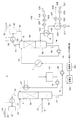
(第1の実施形態)図1に本発明の第1の実施形態に係る二酸化炭素分離回収システムの概略構成を示す。ここで二酸化炭素分離回収システムは、二酸化炭素を吸収可能な吸収液を用いて、化石燃料の燃焼により生成された燃焼排ガスに含まれる二酸化炭素を回収するものである。 (First Embodiment) FIG. 1 shows a schematic configuration of a carbon dioxide separation and recovery system according to a first embodiment of the present invention. Here, the carbon dioxide separation and recovery system recovers carbon dioxide contained in the combustion exhaust gas generated by the combustion of fossil fuel using an absorbing solution capable of absorbing carbon dioxide.
図1に示すように二酸化炭素分離回収システム1は、燃焼排ガス2aに含まれる二酸化炭素を吸収液に吸収させる吸収塔3と、吸収塔3から二酸化炭素を吸収した吸収液(以下、リッチ液4aと記す)が供給され、このリッチ液4aを加熱し、吸収液から水蒸気を含む二酸化炭素ガスを放出させて、二酸化炭素ガスと水蒸気とを含む排出ガス2dを排出し、吸収液を再生する再生塔5とを備える。
As shown in FIG. 1, the carbon dioxide separation and
例えば、火力発電所などの発電設備において生成された燃焼排ガス2aが、排ガス導入ライン8を介して吸収塔3の下部に供給され、吸収塔3の頂部から二酸化炭素が取り除かれた燃焼排ガス2bが排出されるようになっている。
For example,
吸収塔3は、吸収液が二酸化炭素を吸収することにより生成されたリッチ液4aを貯留する吸収塔スチル(タンク)3aを有する。同様に、再生塔5は、リッチ液4aが二酸化炭素ガスを放出することにより再生された吸収液(以下、リーン液4bと記す)を貯留する再生塔スチル(タンク)5aを有する。
The
ここで、二酸化炭素を吸収可能な吸収液には、例えばアミン化合物を水に溶かしたアミン化合物水溶液が使用される。 Here, as the absorbing solution capable of absorbing carbon dioxide, for example, an amine compound aqueous solution in which an amine compound is dissolved in water is used.
図1に示すように、再生塔5にはリボイラー6が設けられている。リボイラー6は、発電設備から供給されるプラント蒸気(水蒸気)等の加熱媒体101を熱源として、再生塔スチル5aに貯留されていたリーン液4bの一部を加熱してその温度を上昇させて蒸気を生成し、再生塔5に供給する。リボイラー6には、加熱媒体101から再生塔5内の吸収液(リーン液4b)に供給される熱量を測定するリボイラー入熱量測定装置100が設けられている。リボイラー入熱量測定装置100の詳細は後述する。
As shown in FIG. 1, a reboiler 6 is provided in the
リボイラー6においてリーン液4bを加熱する際、リーン液4bから二酸化炭素ガスが放出され、吸収液蒸気とともに再生塔5に供給される。この吸収液蒸気は、充填層5bを介して再生塔5内を上昇し、リッチ液4aを加熱する。これによりリッチ液4aから二酸化炭素ガスが放出される。充填層5bは、例えば、多孔構造、ハニカム構造等を有するもので構成され、充填層5bを通過する吸収液を撹乱する作用を有するものであればよい。
When heating the
再生塔5から排出された二酸化炭素ガスと吸収液蒸気とを含む排出ガス2dは、ガスライン35を通り、ガス冷却器31によって水分凝縮した後、気液分離器32によって二酸化炭素ガスと吸収液成分を含む還流水とに気液分離される。気液分離器32からの二酸化炭素ガス2eは回収二酸化炭素導出ライン33を介して排出され、貯蔵設備(図示せず)で貯蔵される。また、気液分離器32からの還流水は還流ライン34を介して再生塔5に戻される。
The
吸収塔3と再生塔5との間に、再生塔5から吸収塔3に供給されるリーン液4bを熱源として、吸収塔3から再生塔5に供給されるリッチ液4aを加熱する再生熱交換器7が設けられ、リーン液4bの熱を回収するように構成されている。ここで、上述したように、再生塔5においてリッチ液4aから二酸化炭素ガスを放出させる際、リッチ液4aはリボイラー6からの高温の蒸気を熱源として加熱される。従って、再生熱交換器7に供給されるリーン液4bの温度は比較的高く、このリーン液4bが熱源として用いられている。
Regeneration heat exchange between the
吸収塔3と再生熱交換器7との間に、吸収塔タンク3aの底部から再生熱交換器7にリッチ液4aを供給するリッチ液ライン11が連結されている。このリッチ液ライン11に、吸収塔3からのリッチ液4aを再生熱交換器7に送り込むリッチ液ポンプ12が設けられている。
A rich
再生熱交換器7と再生塔5との間に、再生熱交換器7から再生塔5の上部にリッチ液4aを供給するリッチ液ライン13が連結されている。
A rich
再生塔5と再生熱交換器7との間に、再生塔タンク5aの底部から再生熱交換器7にリーン液4bを供給するリーン液ライン14が連結されている。このリーン液ライン14に、再生塔5からのリーン液4bを再生熱交換器7に送り込むリーン液ポンプ15が設けられている。
Connected between the
再生熱交換器7からのリーン液4bは、緩衝タンク10に貯留される。緩衝タンク10に貯留されているリーン液4bは、ポンプ16により吸収塔3の上部へ送り込まれる。ポンプ16と吸収塔3との間には吸収液冷却器17が設けられている。吸収液冷却器17は、冷却水(冷却媒体)を冷却源として、吸収塔3に供給される吸収液を冷却する。
The
吸収塔3の上部に供給された吸収液は、吸収塔3内において上部から吸収塔タンク3aに向けて下降する。一方、吸収塔3に供給された燃焼排ガス2aは、吸収塔3内において下部から頂部に向けて上昇する。そのため、二酸化炭素を含む燃焼排ガス2aと吸収液とが充填層3bにおいて向流接触(直接接触)し、吸収液が燃焼排ガス2a中の二酸化炭素を吸収し、リッチ液4aが生成される。二酸化炭素が取り除かれた燃焼排ガス2bは、吸収塔3の頂部から排出され、リッチ液4aは吸収塔3の吸収塔タンク3aに貯留される。充填層3bは、例えば、多孔構造、ハニカム構造等を有するもので構成され、充填層3bを通過する吸収液を撹乱する作用を有するものであればよい。
The absorption liquid supplied to the upper part of the
吸収塔3の頂部から排出された燃焼排ガス2bは、ガス冷却器21によって冷却されて水分凝縮した後、気液分離器22によって排ガスと吸収液成分を含む還流水とに気液分離される。気液分離器22からの排ガス2cは排ガス導出ライン23を介して系外に排出され、還流水は還流ライン24を介して吸収塔3に戻される。
The
次に、リボイラー入熱量測定装置100について説明する。リボイラー入熱量測定装置100は、供給ライン105を介して、リボイラー6に水蒸気等の加熱媒体101を供給する。供給ライン105には、加熱媒体101の温度を測定する温度センサ102、圧力を測定する圧力センサ103、及び流量を測定する流量センサ104が設けられている。すなわち、温度センサ102、圧力センサ103、及び流量センサ104は、リボイラー6の入口における加熱媒体101の温度、圧力、及び流量を測定している。
Next, the reboiler heat
リボイラー6において吸収液に熱を供給した加熱媒体101は、排出ライン110を介して排出される。排出ライン110には、リボイラー6から排出された加熱媒体101を冷却する冷却器120が設けられている。リボイラー6に供給される加熱媒体101が水蒸気であった場合、リボイラー6から排出される加熱媒体101は水(液体)及び水蒸気(気体)を含む気液二相流体である。リボイラー6から排出された加熱媒体101中の水蒸気は、冷却器120により全て凝縮される。従って、冷却器120より下流側の排出ライン110を流れる加熱媒体101は水(液体)となる。
The
冷却器120より下流側の排出ライン110には、加熱媒体101の温度を測定する温度センサ111が設けられている。
A temperature sensor 111 that measures the temperature of the
冷却器120には、供給ライン125を介して、リボイラー6から排出された加熱媒体101を冷却するための冷却媒体121が供給される。冷却媒体121は例えば水である。供給ライン125には、冷却媒体121の温度を測定する温度センサ122及び流量を測定する流量センサ123が設けられている。すなわち、温度センサ122及び流量センサ123は、冷却器120の入口における冷却媒体121の温度及び流量を測定している。
A cooling medium 121 for cooling the
冷却器120において加熱媒体101を冷却した冷却媒体121は、排出ライン126を介して冷却器120から排出される。排出ライン126には、冷却器121から排出された冷却媒体121の温度を測定する温度センサ127が設けられている。すなわち、温度センサ127は、冷却器120の出口における冷却媒体121の温度を測定している。
The cooling medium 121 that has cooled the
リボイラー6において加熱媒体101から吸収液に供給される熱量Qは、リボイラー6入口における加熱媒体101の単位重量当たりの保有熱量(エンタルピーHi)と、冷却器120より下流側における加熱媒体101の単位重量当たりの保有熱量(エンタルピーHlo)との差に加熱媒体流量(Gi)を乗じた値から、冷却器120における加熱媒体101からの除熱量Qrを減じたものに相当し、以下の数式1で表すことができる。
数式1:Q=Gi×(Hi−Hlo)−Qr
The amount of heat Q supplied from the
Formula 1: Q = Gi × (Hi−Hlo) −Qr
リボイラー6入口の加熱媒体101の単位重量当たりの保有熱量(エンタルピーHi)は、温度センサ102及び圧力センサ103の測定値を用いて、日本機械学会等で作成している蒸気表から求めることができる。加熱媒体流量(Gi)は、流量センサ104の測定値である。
The amount of heat (enthalpy Hi) per unit weight of the
また、冷却器120より下流側における加熱媒体101の単位重量当たりの保有熱量(エンタルピーHlo)は、温度センサ111及び圧力センサ103の測定値から求めることができる。
Further, the amount of heat (enthalpy Hlo) per unit weight of the
また、冷却器120における除熱量Qrは、温度センサ122の測定値Ti、温度センサ127の測定値To、流量センサ123の測定値Gr、冷却媒体121の比熱Cprを用いて、以下の数式2で求めることができる。
数式2:Qr=Gr×Cpr×(To−Ti)
The heat removal amount Qr in the cooler 120 is expressed by the following formula 2 using the measured value Ti of the
Formula 2: Qr = Gr × Cpr × (To-Ti)
従って、各センサの測定値を数式1及び数式2に代入することで、リボイラー6において加熱媒体101から吸収液に供給される熱量Qを求めることができる。
Therefore, by substituting the measured values of each sensor into
例えば、演算部150が、温度センサ102、圧力センサ103、流量センサ104、温度センサ111、温度センサ122、流量センサ123、温度センサ127の測定値を取得し、記憶部151に記憶されている蒸気表を参照してエンタルピーHi及びエンタルピーHloを求め、数式2及び数式1の計算を行うことで、熱量Qを算出する。
For example, the
このように本実施形態では、リボイラー6から排出された加熱媒体101を冷却器120で凝縮し、加熱媒体101を全て液体にしてから単位重量当たりの保有熱量(エンタルピー:Hlo)を求めている。そして、リボイラー6入口における加熱媒体101の保有熱量から、冷却器120より下流側の加熱媒体101の保有熱量と、冷却器120における除熱量Qrとを減じることで、リボイラー6において加熱媒体101から吸収液に供給される熱量Qを求めている。
As described above, in the present embodiment, the
そのため、二酸化炭素分離回収システム1の運転条件の変更に伴いリボイラー6から排出される加熱媒体101の蒸気成分と液成分との流量比率が変わっても、リボイラー6において加熱媒体101から吸収液に供給される熱量Qを、簡単かつ正確に算出することができる。
Therefore, even if the flow rate ratio of the vapor component and the liquid component of the
なお、上記実施形態では、加熱媒体101の流量を測定する流量センサ104を供給ライン105に設けていたが、冷却器120より下流側の排出ライン110に設けてもよい。蒸気(気体)よりも液体の流量を測定する方が容易なためである。
In the above embodiment, the
また、上記実施形態において、冷却器120より下流側の排出ライン110に圧力センサを設け、この圧力センサと温度センサ111の測定値に基づいて、冷却器120より下流側の加熱媒体101の単位重量当たりの保有熱量(エンタルピー:エンタルピー:Hlo)を求めるようにしてもよい。
In the above embodiment, a pressure sensor is provided in the
また、上記実施形態において、流量計123は供給ライン125でなく、排出ライン126に設けてもよい。
In the above embodiment, the
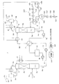
(第2の実施形態)図2に本発明の第2の実施形態に係る二酸化炭素分離回収システムの概略構成を示す。本実施形態は、図1に示す第1の実施形態と比較して、リボイラー入熱量測定装置100の構成が異なる。図2において、図1に示す第1の実施形態と同一部分には同一符号を付して説明を省略する。
(Second Embodiment) FIG. 2 shows a schematic configuration of a carbon dioxide separation and recovery system according to a second embodiment of the present invention. This embodiment differs from the first embodiment shown in FIG. 1 in the configuration of the reboiler heat
図2に示すように、リボイラー6から排出された加熱媒体101は、排出ライン110を介して気液分離器130に供給される。気液分離器130は、加熱媒体101中の液相成分140と気相成分141を分離する。気相成分141は、気液分離器130の上部から排出される。液相成分140は、重力によって気液分離器130の下部に溜まり、排出ライン131を介して排出される。
As shown in FIG. 2, the
排出ライン131には、液相成分140の温度を測定する温度センサ132、圧力を測定する圧力センサ133、及び流量を測定する流量センサ134が設けられている。
The
液相成分140が保有する熱量Qloは以下の数式3から算出できる。
数式3:Qlo=Go×Hlo
The amount of heat Qlo held by the
Formula 3: Qlo = Go × Hlo
ここで、液相成分140の単位重量当たりの保有熱量(エンタルピーHlo)は、温度センサ132及び圧力センサ133の測定値から求めることができる。また、液相成分140の流量Goは、流量センサ134の測定値である。
Here, the amount of heat (enthalpy Hlo) per unit weight of the
気液分離器130から排出される気相成分141の流量Gvoは、リボイラー6入口の加熱媒体101の流量Gi(流量センサ104の測定値)を用いて、以下の数式4で表される。
数式4:Gvo=Gi−Go
The flow rate Gvo of the
Formula 4: Gvo = Gi-Go
気液分離器130から気相成分141は、温度センサ135により温度が測定され、圧力センサ136により圧力が測定される。温度センサ135及び圧力センサ136の測定値から、気相成分141の単位重量当たりの保有熱量(エンタルピーHi’)を求めることができる。気液分離器130から気相成分141として排出される熱量Qvoは、以下の数式5で表される。
数式5:Qvo=Gvo×Hi’
The temperature of the
Formula 5: Qvo = Gvo × Hi ′
従って、リボイラー6において加熱媒体101から吸収液に供給される熱量Qは、以下の数式6から求めることができる。
数式6:Q=Gi×Hi−Gvo×Hi’−Qlo
=Gi×Hi−(Gi−Go)×Hi’−Go×Hlo
=Gi×(Hi−Hi’)+Go×(Hi’−Hlo)
Therefore, the amount of heat Q supplied from the
Formula 6: Q = Gi * Hi-Gvo * Hi'-Ql o
= Gi * Hi- (Gi-Go) * Hi'-Go * Hl o
= Gi × (Hi−Hi ′) + Go × (Hi′−Hl o )
このように、本実施形態によれば、リボイラー6入口における加熱媒体101の温度、圧力を温度センサ102、圧力センサ103で測定し、気液分離器130により気液分離された加熱媒体101の液相成分140の温度、圧力、流量を温度センサ132、圧力センサ133、流量センサ134で測定し、気相成分141の温度、圧力を温度センサ135、圧力センサ136で測定し、上述の数式6に測定値を代入することで、熱量Qを求めている。すなわち、リボイラー6入口における加熱媒体101の単位重量当たりの保有熱量と気相成分141の単位重量当たりの保有熱量との差分にリボイラー6入口における加熱媒体101の流量を乗じた値と、気相成分141の単位重量当たりの保有熱量と液相成分140の単位重量当たりの保有熱量との差分に、液相成分140の流量(=リボイラー6で凝縮した加熱媒体101の流量)を乗じた値とを加算することで、熱量Qを求めている。
As described above, according to this embodiment, the temperature and pressure of the
そのため、二酸化炭素分離回収システム1の運転条件の変更に伴いリボイラー6から排出される加熱媒体101の蒸気成分と液成分との流量比率が変わっても、リボイラー6において加熱媒体101から吸収液に供給される熱量Qを、簡単かつ正確に算出することができる。
Therefore, even if the flow rate ratio of the vapor component and the liquid component of the
なお、数式6から分かるように、本実施形態では熱量Qを算出するにあたり流量センサ104の測定値は用いないため、流量センサ104を省略した構成としてもよい。
As can be seen from Equation 6, in this embodiment, the measurement value of the
(第3の実施形態)図3に本発明の第3の実施形態に係る二酸化炭素分離回収システムの概略構成を示す。本実施形態は、図2に示す第2の実施形態と比較して、リッチ液ライン13に加熱装置40を設けた点が異なる。図3において、図2に示す第2の実施形態と同一部分には同一符号を付して説明を省略する。
(Third Embodiment) FIG. 3 shows a schematic configuration of a carbon dioxide separation and recovery system according to a third embodiment of the present invention. This embodiment is different from the second embodiment shown in FIG. 2 in that a
加熱装置40は、気液分離器130から排出された加熱媒体101の気相成分141を熱源として、リッチ液4aを加熱する。加熱装置40により加熱されたリッチ液4aは再生塔5に供給される。
The
このように本実施形態は、加熱媒体101(水蒸気)が凝縮する時の膨大な潜熱を利用してリッチ液4aを加熱する。そのため、加熱媒体101の流量がリッチ液4aの流量と比較して少ない場合であっても、リッチ液4aを更に昇温することができ、吸収液の再生のために外部から再生塔5に供給される熱量を削減することができる。
As described above, in the present embodiment, the
なお、本発明は上記実施形態そのままに限定されるものではなく、実施段階ではその要旨を逸脱しない範囲で構成要素を変形して具体化できる。また、上記実施形態に開示されている複数の構成要素の適宜な組み合わせにより、種々の発明を形成できる。例えば、実施形態に示される全構成要素から幾つかの構成要素を削除してもよい。さらに、異なる実施形態にわたる構成要素を適宜組み合わせてもよい。 Note that the present invention is not limited to the above-described embodiment as it is, and can be embodied by modifying the constituent elements without departing from the scope of the invention in the implementation stage. In addition, various inventions can be formed by appropriately combining a plurality of components disclosed in the embodiment. For example, some components may be deleted from all the components shown in the embodiment. Furthermore, constituent elements over different embodiments may be appropriately combined.
1 二酸化炭素分離回収システム
3 吸収塔
5 再生塔
6 リボイラー
7 再生熱交換器
100 リボイラー入熱量測定装置
120 冷却器
130 気液分離器
DESCRIPTION OF
Claims (8)
前記吸収塔から二酸化炭素を吸収した吸収液が供給され、当該吸収液から蒸気を含む二酸化炭素ガスを放出させるとともに当該吸収液を再生し、放出された二酸化炭素ガス及び蒸気を含む排出ガスを排出する再生塔と、
前記吸収塔と前記再生塔との間に設けられ、前記再生塔から前記吸収塔に供給される再生された吸収液を熱源として、前記吸収塔から前記再生塔に供給される二酸化炭素を吸収した吸収液を加熱する再生熱交換器と、
前記再生塔に連結され、加熱媒体を用いて前記再生塔内の吸収液を加熱するリボイラーと、
前記加熱媒体から前記吸収液に供給される熱量を測定する測定装置と、
を備え、
前記測定装置は、前記リボイラーから排出される前記加熱媒体を冷却する冷却器を有し、前記リボイラーに供給される前記加熱媒体の保有熱量から、前記冷却器により冷却された前記加熱媒体の保有熱量と前記冷却器における前記加熱媒体からの除熱量とを減じて、前記加熱媒体から前記吸収液に供給される熱量を求めることを特徴とする二酸化炭素分離回収システム。 An absorption tower for absorbing carbon dioxide contained in the combustion exhaust gas into the absorption liquid;
An absorption liquid that absorbs carbon dioxide is supplied from the absorption tower, and carbon dioxide gas containing vapor is released from the absorption liquid and the absorption liquid is regenerated, and the discharged carbon dioxide gas and exhaust gas containing vapor are discharged. A regenerating tower,
The carbon dioxide supplied from the absorption tower to the regeneration tower is absorbed by the regenerated absorption liquid provided between the absorption tower and the regeneration tower and supplied from the regeneration tower to the absorption tower as a heat source. A regenerative heat exchanger for heating the absorption liquid;
A reboiler connected to the regeneration tower and heating the absorbent in the regeneration tower using a heating medium;
A measuring device for measuring the amount of heat supplied from the heating medium to the absorbing liquid;
With
The measuring device includes a cooler that cools the heating medium discharged from the reboiler, and the retained heat amount of the heating medium cooled by the cooler from the retained heat amount of the heating medium supplied to the reboiler. And the amount of heat removed from the heating medium in the cooler to determine the amount of heat supplied from the heating medium to the absorbing liquid.
前記リボイラーに供給される前記加熱媒体の温度を測定する第1温度センサと、
前記リボイラーに供給される前記加熱媒体の圧力を測定する圧力センサと、
前記リボイラーに供給される前記加熱媒体の質量流量又は前記冷却器により冷却された前記加熱媒体の質量流量を測定する第1流量センサと、
前記冷却器により冷却された前記加熱媒体の温度を測定する第2温度センサと、
を有し、
前記第1温度センサ及び前記圧力センサの測定値に基づいて、前記リボイラーに供給される前記加熱媒体の単位重量当たりの保有熱量を求め、この単位重量当たりの保有熱量に前記流量センサの測定値を乗じて、前記リボイラーに供給される前記加熱媒体の保有熱量を算出し、
前記第2温度センサ及び前記圧力センサの測定値に基づいて、前記冷却器により冷却された前記加熱媒体の単位重量当たりの保有熱量を求め、この単位重量当たりの保有熱量に前記流量センサの測定値を乗じて、前記冷却器により冷却された前記加熱媒体の保有熱量を算出することを特徴とする請求項1に記載の二酸化炭素分離回収システム。 The measuring device is
A first temperature sensor for measuring a temperature of the heating medium supplied to the reboiler;
A pressure sensor for measuring the pressure of the heating medium supplied to the reboiler;
A first flow rate sensor for measuring a mass flow rate of the heating medium supplied to the reboiler or a mass flow rate of the heating medium cooled by the cooler;
A second temperature sensor for measuring the temperature of the heating medium cooled by the cooler;
Have
Based on the measured values of the first temperature sensor and the pressure sensor, the amount of retained heat per unit weight of the heating medium supplied to the reboiler is obtained, and the measured value of the flow sensor is used as the retained amount of heat per unit weight. Multiply by calculating the amount of heat held by the heating medium supplied to the reboiler,
Based on the measured values of the second temperature sensor and the pressure sensor, the amount of retained heat per unit weight of the heating medium cooled by the cooler is obtained, and the measured value of the flow rate sensor is obtained as the retained amount of heat per unit weight. The carbon dioxide separation and recovery system according to claim 1, wherein the amount of heat retained by the heating medium cooled by the cooler is calculated by multiplying by.
前記冷却器に供給される冷却媒体の温度を測定する第3温度センサと、
前記冷却器から排出される前記冷却媒体の温度を測定する第4温度センサと、
前記冷却器に供給される前記冷却媒体の質量流量又は前記冷却器から排出される前記冷却媒体の質量流量を測定する第2流量センサと、
を有し、
前記第3温度センサの測定値と前記第4温度センサの測定値との差分に、前記第2流量センサの測定値と前記冷却媒体の比熱とを乗じて、前記冷却器における前記加熱媒体からの除熱量を算出することを特徴とする請求項1又は2に記載の二酸化炭素分離回収システム。 The measuring device is
A third temperature sensor for measuring the temperature of the cooling medium supplied to the cooler;
A fourth temperature sensor for measuring the temperature of the cooling medium discharged from the cooler;
A second flow rate sensor for measuring a mass flow rate of the cooling medium supplied to the cooler or a mass flow rate of the cooling medium discharged from the cooler;
Have
The difference between the measured value of the third temperature sensor and the measured value of the fourth temperature sensor is multiplied by the measured value of the second flow rate sensor and the specific heat of the cooling medium to obtain the difference from the heating medium in the cooler. The carbon dioxide separation and recovery system according to claim 1 or 2, wherein a heat removal amount is calculated.
前記吸収塔から二酸化炭素を吸収した吸収液が供給され、当該吸収液から蒸気を含む二酸化炭素ガスを放出させるとともに当該吸収液を再生し、放出された二酸化炭素ガス及び蒸気を含む排出ガスを排出する再生塔と、
前記吸収塔と前記再生塔との間に設けられ、前記再生塔から前記吸収塔に供給される再生された吸収液を熱源として、前記吸収塔から前記再生塔に供給される二酸化炭素を吸収した吸収液を加熱する再生熱交換器と、
前記再生塔に連結され、加熱媒体を用いて前記再生塔内の吸収液を加熱するリボイラーと、
前記加熱媒体から前記吸収液に供給される熱量を測定する測定装置と、
を備え、
前記測定装置は、
前記リボイラーに供給される前記加熱媒体の質量流量を測定する第1流量センサと、
前記リボイラーから排出される前記加熱媒体を気液分離する気液分離器と、
前記気液分離器から排出される液相成分の質量流量を測定する第2流量センサと、
を有し、
前記リボイラーに供給される前記加熱媒体の単位重量当たりの保有熱量から、前記気液分離器から排出される気相成分の単位重量当たりの保有熱量を減じた値に、前記リボイラーに供給される前記加熱媒体の質量流量を乗じた値と、前記気相成分の単位重量当たりの保有熱量から前記液相成分の単位重量当たりの保有熱量を減じた値に、前記液相成分の質量流量を乗じた値とを加算して、前記加熱媒体から前記吸収液に供給される熱量を求めることを特徴とする二酸化炭素分離回収システム。 An absorption tower for absorbing carbon dioxide contained in the combustion exhaust gas into the absorption liquid;
An absorption liquid that absorbs carbon dioxide is supplied from the absorption tower, and carbon dioxide gas containing vapor is released from the absorption liquid and the absorption liquid is regenerated, and the discharged carbon dioxide gas and exhaust gas containing vapor are discharged. A regenerating tower,
The carbon dioxide supplied from the absorption tower to the regeneration tower is absorbed by the regenerated absorption liquid provided between the absorption tower and the regeneration tower and supplied from the regeneration tower to the absorption tower as a heat source. A regenerative heat exchanger for heating the absorption liquid;
A reboiler connected to the regeneration tower and heating the absorbent in the regeneration tower using a heating medium;
A measuring device for measuring the amount of heat supplied from the heating medium to the absorbing liquid;
With
The measuring device is
A first flow rate sensor for measuring a mass flow rate of the heating medium supplied to the reboiler;
A gas-liquid separator for gas-liquid separation of the heating medium discharged from the reboiler;
A second flow rate sensor for measuring a mass flow rate of the liquid phase component discharged from the gas-liquid separator;
Have
The heat supplied per unit weight of the heating medium supplied to the reboiler is subtracted from the heat held per unit weight of the gas phase component discharged from the gas-liquid separator, and supplied to the reboiler. The value obtained by multiplying the mass flow rate of the heating medium and the value obtained by subtracting the heat amount per unit weight of the liquid phase component from the amount of heat per unit weight of the gas phase component multiplied by the mass flow rate of the liquid phase component. A carbon dioxide separation and recovery system characterized in that the amount of heat supplied from the heating medium to the absorption liquid is obtained by adding the value.
前記リボイラーに供給される前記加熱媒体の温度を測定する第1温度センサと、
前記リボイラーに供給される前記加熱媒体の圧力を測定する第1圧力センサと、
前記液相成分の温度を測定する第2温度センサと、
前記液相成分の圧力を測定する第2圧力センサと、
前記気相成分の温度を測定する第3温度センサと、
前記気相成分の圧力を測定する第3圧力センサと、
を有し、
前記第1温度センサ及び前記第1圧力センサの測定値に基づいて、前記リボイラーに供給される前記加熱媒体の単位重量当たりの保有熱量を求め、
前記第2温度センサ及び前記第2圧力センサの測定値に基づいて、前記液相成分の単位重量当たりの保有熱量を求め、
前記第3温度センサ及び前記第3圧力センサの測定値に基づいて、前記気相成分の単位重量当たりの保有熱量を求めることを特徴とする請求項4に記載の二酸化炭素分離回収システム。 The measuring device is
A first temperature sensor for measuring a temperature of the heating medium supplied to the reboiler;
A first pressure sensor for measuring the pressure of the heating medium supplied to the reboiler;
A second temperature sensor for measuring the temperature of the liquid phase component;
A second pressure sensor for measuring the pressure of the liquid phase component;
A third temperature sensor for measuring the temperature of the gas phase component;
A third pressure sensor for measuring the pressure of the gas phase component;
Have
Based on the measured values of the first temperature sensor and the first pressure sensor, obtain the amount of heat retained per unit weight of the heating medium supplied to the reboiler,
Based on the measured values of the second temperature sensor and the second pressure sensor, the amount of retained heat per unit weight of the liquid phase component is obtained,
5. The carbon dioxide separation and recovery system according to claim 4, wherein a retained heat amount per unit weight of the gas phase component is obtained based on measurement values of the third temperature sensor and the third pressure sensor.
前記吸収塔から二酸化炭素を吸収した吸収液が供給され、当該吸収液から蒸気を含む二酸化炭素ガスを放出させるとともに当該吸収液を再生し、放出された二酸化炭素ガス及び蒸気を含む排出ガスを排出する再生塔と、
前記吸収塔と前記再生塔との間に設けられ、前記再生塔から前記吸収塔に供給される再生された吸収液を熱源として、前記吸収塔から前記再生塔に供給される二酸化炭素を吸収した吸収液を加熱する再生熱交換器と、
前記再生塔に連結され、加熱媒体を用いて前記再生塔内の吸収液を加熱するリボイラーと、
を備える二酸化炭素分離回収システムの前記リボイラーにおいて、前記加熱媒体から前記吸収液に供給される熱量を測定するリボイラー入熱量測定方法であって、
前記リボイラーに供給される前記加熱媒体の第1保有熱量を算出する工程と、
前記リボイラーから排出される前記加熱媒体を冷却器により冷却する工程と、
前記冷却器により冷却された前記加熱媒体の第2保有熱量を算出する工程と、
前記冷却器における前記加熱媒体からの除熱量を算出する工程と、
前記第1保有熱量から、前記第2保有熱量及び前記除熱量を減じて、前記加熱媒体から前記吸収液に供給される熱量を求める工程と、
を有することを特徴とするリボイラー入熱量測定方法。 An absorption tower for absorbing carbon dioxide contained in the combustion exhaust gas into the absorption liquid;
An absorption liquid that absorbs carbon dioxide is supplied from the absorption tower, and carbon dioxide gas containing vapor is released from the absorption liquid and the absorption liquid is regenerated, and the discharged carbon dioxide gas and exhaust gas containing vapor are discharged. A regenerating tower,
The carbon dioxide supplied from the absorption tower to the regeneration tower is absorbed by the regenerated absorption liquid provided between the absorption tower and the regeneration tower and supplied from the regeneration tower to the absorption tower as a heat source. A regenerative heat exchanger for heating the absorption liquid;
A reboiler connected to the regeneration tower and heating the absorbent in the regeneration tower using a heating medium;
In the reboiler of the carbon dioxide separation and recovery system comprising: a reboiler heat input measurement method for measuring the amount of heat supplied from the heating medium to the absorption liquid,
Calculating a first stored heat amount of the heating medium supplied to the reboiler;
Cooling the heating medium discharged from the reboiler with a cooler;
Calculating a second retained heat amount of the heating medium cooled by the cooler;
Calculating a heat removal amount from the heating medium in the cooler;
Subtracting the second retained heat amount and the heat removal amount from the first retained heat amount to obtain the amount of heat supplied from the heating medium to the absorbing liquid;
A reboiler heat input measuring method characterized by comprising:
前記吸収塔から二酸化炭素を吸収した吸収液が供給され、当該吸収液から蒸気を含む二酸化炭素ガスを放出させるとともに当該吸収液を再生し、放出された二酸化炭素ガス及び蒸気を含む排出ガスを排出する再生塔と、
前記吸収塔と前記再生塔との間に設けられ、前記再生塔から前記吸収塔に供給される再生された吸収液を熱源として、前記吸収塔から前記再生塔に供給される二酸化炭素を吸収した吸収液を加熱する再生熱交換器と、
前記再生塔に連結され、加熱媒体を用いて前記再生塔内の吸収液を加熱するリボイラーと、
を備える二酸化炭素分離回収システムの前記リボイラーにおいて、前記加熱媒体から前記吸収液に供給される熱量を測定するリボイラー入熱量測定方法であって、
前記リボイラーに供給される前記加熱媒体の単位重量当たりの第1保有熱量を算出する工程と、
前記リボイラーから排出される前記加熱媒体を気液分離器により気液分離する工程と、 前記気液分離器から排出される液相成分の単位重量当たりの第2保有熱量を算出する工程と、
前記気液分離器から排出される気相成分の単位重量当たりの第3保有熱量を算出する工程と、
前記リボイラーに供給される前記加熱媒体の第1質量流量を測定する工程と、
前記液相成分の第2質量流量を測定する工程と、
単位重量当たりの前記第1保有熱量と前記第3保有熱量との差分に前記第1質量流量を乗じた値と、単位重量当たりの前記第3保有熱量と前記第2保有熱量との差分に前記第2質量流量を乗じた値とを加算して、前記加熱媒体から前記吸収液に供給される熱量を求める工程と、
を有することを特徴とするリボイラー入熱量測定方法。 An absorption tower for absorbing carbon dioxide contained in the combustion exhaust gas into the absorption liquid;
An absorption liquid that absorbs carbon dioxide is supplied from the absorption tower, and carbon dioxide gas containing vapor is released from the absorption liquid and the absorption liquid is regenerated, and the discharged carbon dioxide gas and exhaust gas containing vapor are discharged. A regenerating tower,
The carbon dioxide supplied from the absorption tower to the regeneration tower is absorbed by the regenerated absorption liquid provided between the absorption tower and the regeneration tower and supplied from the regeneration tower to the absorption tower as a heat source. A regenerative heat exchanger for heating the absorption liquid;
A reboiler connected to the regeneration tower and heating the absorbent in the regeneration tower using a heating medium;
In the reboiler of the carbon dioxide separation and recovery system comprising: a reboiler heat input measurement method for measuring the amount of heat supplied from the heating medium to the absorption liquid,
Calculating a first retained heat amount per unit weight of the heating medium supplied to the reboiler;
Gas-liquid separation of the heating medium discharged from the reboiler by a gas-liquid separator; calculating a second retained heat amount per unit weight of the liquid phase component discharged from the gas-liquid separator;
Calculating a third retained heat amount per unit weight of the gas phase component discharged from the gas-liquid separator;
Measuring a first mass flow rate of the heating medium supplied to the reboiler;
Measuring a second mass flow rate of the liquid phase component;
The difference between the first stored heat amount per unit weight and the third stored heat amount multiplied by the first mass flow rate , and the difference between the third stored heat amount and the second stored heat amount per unit weight Adding the value multiplied by the second mass flow rate to obtain the amount of heat supplied from the heating medium to the absorbing liquid;
A reboiler heat input measuring method characterized by comprising:
Priority Applications (6)
| Application Number | Priority Date | Filing Date | Title |
|---|---|---|---|
| JP2010237307A JP5582960B2 (en) | 2010-10-22 | 2010-10-22 | Carbon dioxide separation and recovery system and reboiler heat input measurement method |
| AU2011232812A AU2011232812B2 (en) | 2010-10-22 | 2011-10-07 | Carbon dioxide separation recovery system and method of measuring amount of reboiler input heat |
| CA2754466A CA2754466C (en) | 2010-10-22 | 2011-10-07 | Carbon dioxide separation recovery system and method of measuring amount of reboiler input heat |
| EP11185581.3A EP2444140B1 (en) | 2010-10-22 | 2011-10-18 | Carbon dioxide separation recovery system and method of measuring amount of reboiler input heat |
| CN201110324009.4A CN102527194B (en) | 2010-10-22 | 2011-10-21 | Carbon dioxide separation recovery system and method of measuring amount of reboiler input heat |
| US13/279,041 US8983791B2 (en) | 2010-10-22 | 2011-10-21 | Carbon dioxide separation recovery system and method of measuring amount of reboiler input heat |
Applications Claiming Priority (1)
| Application Number | Priority Date | Filing Date | Title |
|---|---|---|---|
| JP2010237307A JP5582960B2 (en) | 2010-10-22 | 2010-10-22 | Carbon dioxide separation and recovery system and reboiler heat input measurement method |
Publications (2)
| Publication Number | Publication Date |
|---|---|
| JP2012087032A JP2012087032A (en) | 2012-05-10 |
| JP5582960B2 true JP5582960B2 (en) | 2014-09-03 |
Family
ID=44910133
Family Applications (1)
| Application Number | Title | Priority Date | Filing Date |
|---|---|---|---|
| JP2010237307A Active JP5582960B2 (en) | 2010-10-22 | 2010-10-22 | Carbon dioxide separation and recovery system and reboiler heat input measurement method |
Country Status (6)
| Country | Link |
|---|---|
| US (1) | US8983791B2 (en) |
| EP (1) | EP2444140B1 (en) |
| JP (1) | JP5582960B2 (en) |
| CN (1) | CN102527194B (en) |
| AU (1) | AU2011232812B2 (en) |
| CA (1) | CA2754466C (en) |
Families Citing this family (14)
| Publication number | Priority date | Publication date | Assignee | Title |
|---|---|---|---|---|
| JP5767609B2 (en) * | 2012-06-25 | 2015-08-19 | 株式会社東芝 | Carbon dioxide recovery device and operation method thereof |
| US20140041523A1 (en) * | 2012-08-09 | 2014-02-13 | Mitsubishi Heavy Industries, Ltd. | Exhaust gas treatment system |
| MY178577A (en) * | 2012-09-05 | 2020-10-16 | Basf Se | Process for separating off acid gases from a water-comprising fluid stream |
| US10195561B2 (en) * | 2012-09-20 | 2019-02-05 | Mitsubishi Heavy Industries Engineering, Ltd. | Steam supply system and CO2 recovery unit including the same |
| KR101550618B1 (en) | 2014-01-14 | 2015-09-07 | 현대자동차 주식회사 | Reboiling device and regeneration tower |
| KR101618347B1 (en) | 2015-02-17 | 2016-05-04 | (주) 선두솔루션 | Coolant calorimeter that can do pressure cycle test |
| CN105302180B (en) * | 2015-11-26 | 2018-09-21 | 重庆耐德工业股份有限公司 | A kind of temprature control method, system and desorber |
| WO2018189947A1 (en) * | 2017-04-13 | 2018-10-18 | 関西電力株式会社 | Carbon dioxide recovery system and carbon dioxide recovery method |
| JP6913604B2 (en) * | 2017-10-27 | 2021-08-04 | 株式会社東芝 | How to operate the carbon dioxide separation and recovery system and the carbon dioxide separation and recovery system |
| JP7269761B2 (en) * | 2019-03-15 | 2023-05-09 | 三菱重工業株式会社 | Raw material fluid processing plant and raw material fluid processing method |
| CN110175400B (en) * | 2019-05-27 | 2023-04-07 | 浙江大学城市学院 | CO based on high-pressure natural gas processing device 2 Absorption dynamic model and control method |
| CN110411611A (en) * | 2019-07-24 | 2019-11-05 | 河北冀研能源科学技术研究院有限公司 | A kind of high-precision Gateway Station in Heating Network heating load capacity checking device |
| CN111450656A (en) * | 2020-05-29 | 2020-07-28 | 山东兴鲁生物科技有限公司 | Acrolein production waste gas treatment device |
| CN113813749A (en) * | 2021-10-25 | 2021-12-21 | 北京美斯顿科技开发有限公司 | A energy-conserving wisdom carbon island for whole factory exhaust gas carbon entrapment |
Family Cites Families (23)
| Publication number | Priority date | Publication date | Assignee | Title |
|---|---|---|---|---|
| FR2142780B1 (en) * | 1971-06-24 | 1973-06-29 | Inst Francais Du Petrole | |
| US4106916A (en) * | 1977-08-10 | 1978-08-15 | Phillips Petroleum Company | Automatic control of an absorption/stripping process |
| JPS5926926A (en) * | 1982-07-30 | 1984-02-13 | Hitachi Zosen Corp | Apparatus for removing co2 with hot potassium carbonate |
| DK0733396T3 (en) * | 1991-10-09 | 2009-11-23 | Mitsubishi Heavy Ind Ltd | Extraction of carbon dioxide from exhaust gas from combustion |
| JP2964194B2 (en) * | 1992-02-18 | 1999-10-18 | ゴスダルストベンヌイ ナウチノーイスレドバーテリスキー イ ブロエクトヌイ インスティトゥト アゾトノイ ブロムィシュレンノスチ イ ブロドゥクトフ オルガニーチェスコゴ シンテザ | Method for separating carbon monoxide from gas mixtures |
| JP3212524B2 (en) * | 1996-12-16 | 2001-09-25 | 関西電力株式会社 | Control method of flue gas decarbonation equipment |
| DK174407B1 (en) * | 2001-04-05 | 2003-02-17 | Topsoe Haldor As | Process for preparing an aqueous solution of ammonium thiosulfate |
| AU2004258854B2 (en) * | 2003-07-22 | 2009-07-02 | Dow Global Technologies Inc. | Regeneration of acid gas-containing treatment fluids |
| JP4690659B2 (en) * | 2004-03-15 | 2011-06-01 | 三菱重工業株式会社 | CO2 recovery device |
| JP4875303B2 (en) * | 2005-02-07 | 2012-02-15 | 三菱重工業株式会社 | Carbon dioxide recovery system, power generation system using the same, and methods thereof |
| US7632476B2 (en) * | 2006-03-09 | 2009-12-15 | Praxair Technology, Inc. | Method of recovering carbon dioxide from a synthesis gas stream |
| US20070221065A1 (en) * | 2006-03-23 | 2007-09-27 | Adisorn Aroonwilas | Heat recovery gas absorption process |
| CN101479022A (en) * | 2006-05-17 | 2009-07-08 | 赛欧所威有限公司 | Process for treating a gas stream |
| JP5558036B2 (en) * | 2008-09-04 | 2014-07-23 | 株式会社東芝 | Carbon dioxide recovery steam power generation system |
| JP2010100491A (en) * | 2008-10-24 | 2010-05-06 | Toshiba Corp | Device and method for carbon dioxide recovery |
| JP5479949B2 (en) * | 2009-04-08 | 2014-04-23 | 株式会社東芝 | Measuring device, measuring method, and carbon dioxide recovery system |
| JP5148546B2 (en) * | 2009-04-09 | 2013-02-20 | 三菱重工業株式会社 | Heat recovery equipment |
| JP2011177684A (en) * | 2010-03-03 | 2011-09-15 | Toshiba Corp | Carbon dioxide separation and recovery system |
| JP5351816B2 (en) * | 2010-04-08 | 2013-11-27 | 三菱重工業株式会社 | Apparatus and method for recovering carbon dioxide in exhaust gas |
| JP2011240321A (en) * | 2010-04-20 | 2011-12-01 | Babcock Hitachi Kk | Exhaust gas treatment system having carbon dioxide removal device |
| CN103097000A (en) * | 2010-07-20 | 2013-05-08 | 鲍尔斯潘公司 | Absorption media for scrubbing co2 from a gas stream and methods using the same |
| JP5527095B2 (en) * | 2010-08-09 | 2014-06-18 | 株式会社Ihi | Carbon dioxide recovery method and recovery apparatus |
| US8623307B2 (en) * | 2010-09-14 | 2014-01-07 | Alstom Technology Ltd. | Process gas treatment system |
-
2010
- 2010-10-22 JP JP2010237307A patent/JP5582960B2/en active Active
-
2011
- 2011-10-07 AU AU2011232812A patent/AU2011232812B2/en active Active
- 2011-10-07 CA CA2754466A patent/CA2754466C/en active Active
- 2011-10-18 EP EP11185581.3A patent/EP2444140B1/en active Active
- 2011-10-21 CN CN201110324009.4A patent/CN102527194B/en active Active
- 2011-10-21 US US13/279,041 patent/US8983791B2/en active Active
Also Published As
| Publication number | Publication date |
|---|---|
| JP2012087032A (en) | 2012-05-10 |
| EP2444140A2 (en) | 2012-04-25 |
| CA2754466A1 (en) | 2012-04-22 |
| US20120101767A1 (en) | 2012-04-26 |
| AU2011232812A1 (en) | 2012-05-10 |
| CN102527194B (en) | 2014-10-15 |
| US8983791B2 (en) | 2015-03-17 |
| AU2011232812B2 (en) | 2013-08-15 |
| CN102527194A (en) | 2012-07-04 |
| EP2444140B1 (en) | 2018-01-10 |
| EP2444140A3 (en) | 2016-03-23 |
| CA2754466C (en) | 2013-11-26 |
Similar Documents
| Publication | Publication Date | Title |
|---|---|---|
| JP5582960B2 (en) | Carbon dioxide separation and recovery system and reboiler heat input measurement method | |
| JP5331587B2 (en) | Carbon dioxide recovery system | |
| JP6157925B2 (en) | Carbon dioxide separation and recovery device and operation method thereof | |
| JP5479949B2 (en) | Measuring device, measuring method, and carbon dioxide recovery system | |
| JP5868741B2 (en) | Acid gas removal device | |
| JP5767609B2 (en) | Carbon dioxide recovery device and operation method thereof | |
| JP6284383B2 (en) | CO2 recovery device and CO2 recovery method | |
| JP5741690B2 (en) | Carbon dioxide recovery method and recovery apparatus | |
| JP2014520661A (en) | Amine absorbent and CO2 capture method | |
| JP6507089B2 (en) | Carbon dioxide recovery system | |
| JP5758013B2 (en) | Method and system for removing gaseous contaminants | |
| JP2010201379A (en) | Carbon dioxide recovery system | |
| JP5586358B2 (en) | Carbon dioxide separation and recovery system and operation method thereof | |
| JP5707894B2 (en) | Carbon dioxide recovery method and recovery apparatus | |
| AU2014220049B2 (en) | System and method for recovering gas containing CO2 and H2S | |
| JP5237204B2 (en) | CO2 recovery apparatus and method | |
| JP2013173656A (en) | Carbon dioxide separation recovery system and operation method thereof | |
| JP2014113546A (en) | Carbon dioxide recovery device and carbon dioxide recovery method | |
| JP5897142B2 (en) | Steam supply system and CO2 recovery equipment equipped with the same | |
| JP2014205102A (en) | Method and apparatus for recovering carbon dioxide in gas to be treated | |
| JP2011125824A (en) | System for separating/recovering carbon dioxide | |
| JP6043171B2 (en) | Carbon dioxide recovery device | |
| JP2015039670A (en) | Carbon dioxide separation and recovery system and operational method thereof |
Legal Events
| Date | Code | Title | Description |
|---|---|---|---|
| A621 | Written request for application examination |
Free format text: JAPANESE INTERMEDIATE CODE: A621 Effective date: 20130705 |
|
| A977 | Report on retrieval |
Free format text: JAPANESE INTERMEDIATE CODE: A971007 Effective date: 20140228 |
|
| A131 | Notification of reasons for refusal |
Free format text: JAPANESE INTERMEDIATE CODE: A131 Effective date: 20140304 |
|
| A521 | Request for written amendment filed |
Free format text: JAPANESE INTERMEDIATE CODE: A523 Effective date: 20140407 |
|
| TRDD | Decision of grant or rejection written | ||
| A01 | Written decision to grant a patent or to grant a registration (utility model) |
Free format text: JAPANESE INTERMEDIATE CODE: A01 Effective date: 20140617 |
|
| A61 | First payment of annual fees (during grant procedure) |
Free format text: JAPANESE INTERMEDIATE CODE: A61 Effective date: 20140715 |
|
| R151 | Written notification of patent or utility model registration |
Ref document number: 5582960 Country of ref document: JP Free format text: JAPANESE INTERMEDIATE CODE: R151 |