KR20130023484A - Energy saving method and apparatus for carbon dioxide capture in power plant - Google Patents
Energy saving method and apparatus for carbon dioxide capture in power plant Download PDFInfo
- Publication number
- KR20130023484A KR20130023484A KR1020110086271A KR20110086271A KR20130023484A KR 20130023484 A KR20130023484 A KR 20130023484A KR 1020110086271 A KR1020110086271 A KR 1020110086271A KR 20110086271 A KR20110086271 A KR 20110086271A KR 20130023484 A KR20130023484 A KR 20130023484A
- Authority
- KR
- South Korea
- Prior art keywords
- heat
- heat exchanger
- absorbent
- carbon dioxide
- stripping column
- Prior art date
Links
Images
Classifications
-
- B—PERFORMING OPERATIONS; TRANSPORTING
- B01—PHYSICAL OR CHEMICAL PROCESSES OR APPARATUS IN GENERAL
- B01D—SEPARATION
- B01D47/00—Separating dispersed particles from gases, air or vapours by liquid as separating agent
-
- B—PERFORMING OPERATIONS; TRANSPORTING
- B01—PHYSICAL OR CHEMICAL PROCESSES OR APPARATUS IN GENERAL
- B01D—SEPARATION
- B01D53/00—Separation of gases or vapours; Recovering vapours of volatile solvents from gases; Chemical or biological purification of waste gases, e.g. engine exhaust gases, smoke, fumes, flue gases, aerosols
- B01D53/14—Separation of gases or vapours; Recovering vapours of volatile solvents from gases; Chemical or biological purification of waste gases, e.g. engine exhaust gases, smoke, fumes, flue gases, aerosols by absorption
- B01D53/1406—Multiple stage absorption
-
- B—PERFORMING OPERATIONS; TRANSPORTING
- B01—PHYSICAL OR CHEMICAL PROCESSES OR APPARATUS IN GENERAL
- B01D—SEPARATION
- B01D53/00—Separation of gases or vapours; Recovering vapours of volatile solvents from gases; Chemical or biological purification of waste gases, e.g. engine exhaust gases, smoke, fumes, flue gases, aerosols
- B01D53/14—Separation of gases or vapours; Recovering vapours of volatile solvents from gases; Chemical or biological purification of waste gases, e.g. engine exhaust gases, smoke, fumes, flue gases, aerosols by absorption
- B01D53/1412—Controlling the absorption process
-
- B—PERFORMING OPERATIONS; TRANSPORTING
- B01—PHYSICAL OR CHEMICAL PROCESSES OR APPARATUS IN GENERAL
- B01D—SEPARATION
- B01D53/00—Separation of gases or vapours; Recovering vapours of volatile solvents from gases; Chemical or biological purification of waste gases, e.g. engine exhaust gases, smoke, fumes, flue gases, aerosols
- B01D53/14—Separation of gases or vapours; Recovering vapours of volatile solvents from gases; Chemical or biological purification of waste gases, e.g. engine exhaust gases, smoke, fumes, flue gases, aerosols by absorption
- B01D53/1418—Recovery of products
-
- B—PERFORMING OPERATIONS; TRANSPORTING
- B01—PHYSICAL OR CHEMICAL PROCESSES OR APPARATUS IN GENERAL
- B01D—SEPARATION
- B01D53/00—Separation of gases or vapours; Recovering vapours of volatile solvents from gases; Chemical or biological purification of waste gases, e.g. engine exhaust gases, smoke, fumes, flue gases, aerosols
- B01D53/14—Separation of gases or vapours; Recovering vapours of volatile solvents from gases; Chemical or biological purification of waste gases, e.g. engine exhaust gases, smoke, fumes, flue gases, aerosols by absorption
- B01D53/1425—Regeneration of liquid absorbents
-
- B—PERFORMING OPERATIONS; TRANSPORTING
- B01—PHYSICAL OR CHEMICAL PROCESSES OR APPARATUS IN GENERAL
- B01D—SEPARATION
- B01D53/00—Separation of gases or vapours; Recovering vapours of volatile solvents from gases; Chemical or biological purification of waste gases, e.g. engine exhaust gases, smoke, fumes, flue gases, aerosols
- B01D53/34—Chemical or biological purification of waste gases
- B01D53/96—Regeneration, reactivation or recycling of reactants
-
- Y—GENERAL TAGGING OF NEW TECHNOLOGICAL DEVELOPMENTS; GENERAL TAGGING OF CROSS-SECTIONAL TECHNOLOGIES SPANNING OVER SEVERAL SECTIONS OF THE IPC; TECHNICAL SUBJECTS COVERED BY FORMER USPC CROSS-REFERENCE ART COLLECTIONS [XRACs] AND DIGESTS
- Y02—TECHNOLOGIES OR APPLICATIONS FOR MITIGATION OR ADAPTATION AGAINST CLIMATE CHANGE
- Y02A—TECHNOLOGIES FOR ADAPTATION TO CLIMATE CHANGE
- Y02A50/00—TECHNOLOGIES FOR ADAPTATION TO CLIMATE CHANGE in human health protection, e.g. against extreme weather
- Y02A50/20—Air quality improvement or preservation, e.g. vehicle emission control or emission reduction by using catalytic converters
-
- Y—GENERAL TAGGING OF NEW TECHNOLOGICAL DEVELOPMENTS; GENERAL TAGGING OF CROSS-SECTIONAL TECHNOLOGIES SPANNING OVER SEVERAL SECTIONS OF THE IPC; TECHNICAL SUBJECTS COVERED BY FORMER USPC CROSS-REFERENCE ART COLLECTIONS [XRACs] AND DIGESTS
- Y02—TECHNOLOGIES OR APPLICATIONS FOR MITIGATION OR ADAPTATION AGAINST CLIMATE CHANGE
- Y02C—CAPTURE, STORAGE, SEQUESTRATION OR DISPOSAL OF GREENHOUSE GASES [GHG]
- Y02C20/00—Capture or disposal of greenhouse gases
- Y02C20/40—Capture or disposal of greenhouse gases of CO2
-
- Y—GENERAL TAGGING OF NEW TECHNOLOGICAL DEVELOPMENTS; GENERAL TAGGING OF CROSS-SECTIONAL TECHNOLOGIES SPANNING OVER SEVERAL SECTIONS OF THE IPC; TECHNICAL SUBJECTS COVERED BY FORMER USPC CROSS-REFERENCE ART COLLECTIONS [XRACs] AND DIGESTS
- Y02—TECHNOLOGIES OR APPLICATIONS FOR MITIGATION OR ADAPTATION AGAINST CLIMATE CHANGE
- Y02P—CLIMATE CHANGE MITIGATION TECHNOLOGIES IN THE PRODUCTION OR PROCESSING OF GOODS
- Y02P70/00—Climate change mitigation technologies in the production process for final industrial or consumer products
- Y02P70/10—Greenhouse gas [GHG] capture, material saving, heat recovery or other energy efficient measures, e.g. motor control, characterised by manufacturing processes, e.g. for rolling metal or metal working
Abstract
Description
본 발명은 이산화탄소 포집을 위한 흡수 및 탈거공정에 관한 것으로, 좀 더 자세하게는 발전소 보일러의 절탄기와 탈질설비 사이에 배열회수 열교환기를 설치함으로써, 탈질설비로 유입되는 배기가스의 반응온도를 조절하여 탈질 촉매의 탈질성능을 높이는 동시에, 배기가스의 열에너지를 회수하여 산성가스 포집공정의 탈거에너지로 이용하는 장치 및 방법에 관한 것이다.
The present invention relates to an absorption and stripping process for carbon dioxide capture, and more particularly, by installing a heat recovery heat exchanger between a coal firer and a denitrification facility of a power plant boiler, by controlling the reaction temperature of the exhaust gas flowing into the denitrification facility, a denitrification catalyst. The present invention relates to a device and a method for increasing the denitrification performance of a gas and recovering thermal energy of exhaust gas and using the stripping energy of an acid gas collection process.
최근 지구온난화의 원인 물질인 온실가스를 포집하고 저장하는 노력이 국제적으로 경주되고 있다. 특히 온실가스 중 산성가스인 이산화탄소를 줄이기 위하여 화학적 흡수법, 흡착법, 막분리법, 심냉법 등 많은 기술이 개발되고 있다.Recently, efforts to capture and store greenhouse gases, which are the causes of global warming, have been racing internationally. In particular, many technologies such as chemical absorption, adsorption, membrane separation, deep cooling, and the like have been developed to reduce carbon dioxide, which is an acid gas among greenhouse gases.
화력발전소 등 연소설비에서 발생하는 이산화탄소를 제거하기 위하여 사용되는 흡수제를 이용한 화학적 흡수방법은 높은 효율과 안정적인 기술로 가장 많이 연구되고 있다. 이산화탄소를 포집하기 위한 아민계 포집공정은 화학적 흡수기술의 일종으로 발전소에 효과적으로 적용하기 위해서는 사용되는 에너지를 줄이기 위하여 고효율, 저에너지형 흡수제 및 공정의 개선이 필요한 분리기술이다.Chemical absorption methods using absorbents used to remove carbon dioxide from combustion facilities such as thermal power plants have been studied the most with high efficiency and stable technology. The amine-based capture process for capturing carbon dioxide is a kind of chemical absorption technology. It is a separation technology that requires high-efficiency, low-energy absorbents and process improvements in order to reduce the energy used for effective application to power plants.
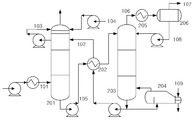
화학적 흡수제를 이용한 이산화탄소 흡수 및 탈거 공정에 대한 흐름도는 도 1과 같다. 냉각된 배기가스(101)는 흡수탑(201)에 유입되고, 통상적으로 40 내지 60℃의 온도에서 흡수제(102)와 접촉되며, 배기가스(101) 중 이산화탄소는 흡수제(102) 내의 화학적 흡수제와 결합한 다음 흡수탑(201) 하단으로 배출되고, 이산화탄소가 제거된 배기가스는 흡수탑(201) 상단으로 배출된다. 이때 순환되는 세척용 물(103)을 이용하거나, 공정의 물 수지를 맞출 수 있도록 공급되는 보충수(104)를 이용하여, 흡수제(102) 또는 증기가 비말하는 것을 방지한다. 출구 가스의 이산화탄소 농도는 흡수제(102)에서의 화학 반응으로 감소시킬 수 있지만, 낮은 출구 이산화탄소 농도를 유지하기 위해서는 흡수탑(201)이 높아져야 한다.A flowchart of a carbon dioxide absorption and stripping process using a chemical absorbent is shown in FIG. 1. The cooled
화학적 결합에 의해 이산화탄소를 흡수한 흡수제(105)는 열교환기(202)를 거쳐 가열된 후, 탈거탑(203)의 상부로 주입된다. 포화 흡수제(105)의 재생은 높은 온도(100 내지 140℃) 및 대기압 정도의 압력 하에 탈거탑(203)에서 수행된다. 재생 조건을 유지하기 위하여, 터빈 수증기(109) 등의 열원이 리보일러(204)로 공급되며, 이 과정에서 열에너지가 소모된다. 공급되는 에너지는 포화 흡수제(105)에 화학적으로 결합되어 있는 이산화탄소를 탈거시키고, 탈거된 이산화탄소와 수증기의 혼합가스(106)는 응축기(205)와 리플럭스 드럼(206)을 거쳐 분리된 후, 이산화탄소(107)는 배출되어 별도로 처리되고, 응축수(108)는 회수되어 탈거탑(203)로 다시 공급된다. 이산화탄소가 탈거되어 재생된 흡수제(102)는 열교환기(202)를 거쳐 흡수탑 수준의 온도로 냉각된 후, 흡수탑(201)으로 펌프에 의해 이송된다.The absorbent 105 absorbing carbon dioxide by chemical bonding is heated through the
상기 이산화탄소 흡수 및 탈거공정에서 흡수제의 재생을 위해 많은 에너지가 소모되므로, 재생에너지를 줄이기 위한 흡수제와 관련 공정의 개발이 절실히 요구되고 있다. 종래기술에서는 이산화탄소의 탈거에너지를 얻기 위하여, 발전소 보일러의 고압, 중압, 저압 스팀 터빈으로부터 스팀을 추출하여 탈거탑의 리보일러에 공급하여 탈거시켰다. 또한, 대한민국 특허공개 제2010-73614호에서는 연돌 배가스의 폐열을 탈거에너지로 이용하였다. 특히 탈거공정의 장치 및 흐름을 최적화하여 가장 경제적인 이산화탄소 흡수효율을 얻고자 하는 연구가 많은 연구자에 의해 연구되고 있다.Since a lot of energy is consumed for the regeneration of the absorbent in the carbon dioxide absorption and stripping process, the development of absorbents and related processes to reduce the renewable energy is urgently required. In the prior art, in order to obtain carbon dioxide stripping energy, steam is extracted from a high pressure, medium pressure, and low pressure steam turbine of a power plant boiler and supplied to a reboiler of a stripping tower. In addition, the Republic of Korea Patent Publication No. 2010-73614 used waste heat of the flue flue gas as stripping energy. In particular, many researchers are trying to obtain the most economical carbon dioxide absorption efficiency by optimizing the device and flow of the stripping process.
또한 탈질설비에서는 사용되는 촉매들이 특정 반응온도 영역에서만 높은 효율을 보이므로, 탈질 효율을 높이기 위하여 해당 설비의 온도 조건에 맞는 촉매를 개발하는 연구를 진행하고 있다. 발전소에서 발생하는 질소산화물을 제거하기 위하여 절탄기와 공기예열기 사이에 촉매를 설치하고 있다.In addition, since the catalysts used in the denitrification facility show high efficiency only in a specific reaction temperature range, researches are being conducted to develop catalysts suitable for the temperature conditions of the facility in order to increase the denitrification efficiency. A catalyst is installed between the coke and the air preheater to remove nitrogen oxides from the power plant.
이와 같이, 발전소 이산화탄소 흡수 및 탈거공정에서 흡수제의 재생을 위한 많은 에너지가 소모되므로, 재생에너지를 줄이기 위한 공정의 개발이 요구되고 있다. 그러나 상기 종래의 기술은 보일러 저온, 중온, 고온 스팀터빈으로부터 스팀을 추출하여, 이산화탄소 포집설비의 탈거공정의 열원으로 이용하므로, 발전소의 발전 효율을 크게 감소시킨다. 또한 발전소 탈질공정에서 탈질효율을 맞추기 위해, 특정온도 조건에서 탈질율을 보이는 촉매를 절탄기와 공기예열기 사이에 설치하여 질소산화물을 제거하고 있다. 그러나 이와 같은 공정은 발전소의 발전 부하가 변하거나 사용되는 연료가 바뀌는 등 운전 조건이 바뀌면, 배기가스의 온도가 변하여 질소산화물 제거 효율이 낮아지게 된다.
As such, since much energy for regeneration of the absorbent is consumed in the power plant carbon dioxide absorption and stripping process, development of a process for reducing renewable energy is required. However, the conventional technology extracts steam from the boiler low temperature, medium temperature, and high temperature steam turbine, and uses it as a heat source for the removal process of the carbon dioxide capture facility, thereby greatly reducing the power generation efficiency of the power plant. In addition, in order to match the denitrification efficiency in the power plant denitrification process, a nitrogen oxide is removed by installing a catalyst showing a denitrification rate at a specific temperature condition between the economizer and the air preheater. However, in such a process, when operating conditions are changed, such as a change in the power generation load of a power plant or a fuel used, the temperature of the exhaust gas is changed to reduce the nitrogen oxide removal efficiency.
본 발명의 목적은 발전소 이산화탄소 포집 설비의 에너지 효율 증대 방안을 제공하는 것으로, 구체적으로 발전소 보일러의 절탄기와 탈질설비 사이에 배열회수 열교환기를 설치함으로써, 탈질설비로 유입되는 배기가스의 반응온도를 조절하여 탈질 촉매의 탈질성능을 높이는 동시에, 배기가스의 열에너지를 회수하여 이산화탄소 포집공정의 탈거에너지로 이용하는 장치 및 방법을 제공하는 것이다.
It is an object of the present invention to provide a method for increasing energy efficiency of a power plant carbon dioxide capture facility, and in particular, by installing a heat recovery heat exchanger between a coal firer and a denitrification facility of a power plant boiler, thereby controlling the reaction temperature of the exhaust gas flowing into the denitrification facility. The present invention provides an apparatus and method for improving the denitrification performance of a denitrification catalyst and recovering thermal energy of exhaust gas and using it as stripping energy of a carbon dioxide capture process.
본 발명은 상기 목적을 달성하기 위하여, 흡수제를 이용한 이산화탄소의 흡수가 이루어지는 흡수탑; 흡수탑과 연결되고 흡수제의 재생이 이루어지는 탈거탑; 탈거탑과 연결되고 흡수제의 재생에 필요한 열원을 공급하는 리보일러; 및 발전소 보일러의 절탄기와 배연탈질설비 사이에 설치되어 배기가스의 열을 회수하고, 리보일러와 연결되어 회수한 열을 리보일러의 열원으로 공급하는 배열회수 열교환기를 포함하는 이산화탄소 포집장치를 제공한다.The present invention, in order to achieve the above object, the absorption tower is made of absorption of carbon dioxide using the absorbent; A stripping column connected to the absorption tower and configured to regenerate the absorbent; A reboiler connected to the stripping column and supplying a heat source necessary for regeneration of the absorbent; And a heat recovery heat exchanger installed between a coal-fired denitrification facility and a flue gas denitrification facility of a power plant boiler, and recovering heat of exhaust gas, and supplying the recovered heat to a heat source of the reboiler.
본 발명에 따른 이산화탄소 포집장치는 배열회수 열교환기와 연결되어 배열회수 열교환기로 들어가는 물의 양을 조절함으로써, 배기가스의 온도를 조절하고 회수되는 열량을 제어하는 유량조절기; 배열회수 열교환기와 배연탈질설비 사이에 설치되어 배기가스의 온도를 감지하고, 유량조절기와 연계되는 온도감지기; 탈거탑과 리보일러에 사이에 설치되고 재생 흡수제를 가열하여 불순물을 분리하며, 배열회수 열교환기와 연결되어 열원을 공급받는 리클레이머; 탈거탑과 연결되어 탈거탑에 공급되는 흡수제 보충분을 용해하고, 배열회수 열교환기와 연결되어 열원을 공급받는 흡수제 주입기; 흡수탑과 탈거탑 사이에 설치되어 탈거탑으로 이송되는 포화 흡수제를 예열하고, 배열회수 열교환기와 연결되어 열원을 공급받는 흡수제 예열용 열교환기; 및/또는 탈거탑과 연결되어 탈거탑으로 유입되는 응축액을 가열하고, 배열회수 열교환기와 연결되어 열원을 공급받는 응축액 예열용 열교환기를 추가로 포함할 수 있다.Carbon dioxide collection device according to the present invention is connected to the heat recovery heat exchanger by controlling the amount of water entering the heat recovery heat exchanger, by controlling the temperature of the exhaust gas and controlling the amount of heat recovered; A temperature sensor installed between the heat recovery heat exchanger and the flue gas denitrification system to sense the temperature of the exhaust gas and associated with the flow regulator; A reclaimer installed between the stripping column and the reboiler and separating impurities by heating a regenerative absorbent and connected to a heat recovery heat exchanger to receive a heat source; An absorbent injector connected to the stripping column to dissolve the absorbent supplement supplied to the stripping column, and connected to the heat recovery heat exchanger to receive a heat source; A heat exchanger for preheating the absorbent installed between the absorption tower and the stripping column to preheat the saturated absorbent transferred to the stripping column, and connected to the heat recovery heat exchanger to receive a heat source; And / or a heat exchanger for preheating the condensate connected to the stripping column to heat the condensate flowing into the stripping column and connected to the heat recovery heat exchanger to receive a heat source.
본 발명에서 리보일러는 발전소 터빈과도 연결되어 터빈으로부터 열원을 선택적으로 공급받을 수 있다.In the present invention, the reboiler may also be connected to a power plant turbine to selectively receive a heat source from the turbine.
본 발명에서 흡수제는 아민계, 아미노산염, 무기염계 용액, 암모니아수 및 금속 이온염 용액 등을 사용할 수 있다.In the present invention, the absorbent may be an amine, an amino acid salt, an inorganic salt solution, ammonia water and a metal ion salt solution.
또한, 본 발명은 흡수탑에서 흡수제를 이용하여 이산화탄소를 흡수하는 단계; 발전소 보일러의 절탄기와 배연탈질설비 사이에 설치된 배열회수 열교환기를 통해 배기가스의 열을 회수하는 단계; 회수된 열을 탈거탑과 연결된 리보일러의 열원으로 공급하는 단계; 및 리보일러의 열원을 이용하여 탈거탑에서 흡수제를 재생하는 단계를 포함하는 이산화탄소 포집방법을 제공한다.In addition, the present invention comprises the steps of absorbing carbon dioxide using an absorbent in the absorption tower; Recovering heat of the exhaust gas through a heat recovery heat exchanger installed between the coal firer and the flue gas denitrification facility of the power plant boiler; Supplying the recovered heat to a heat source of the reboiler connected to the stripping column; And it provides a carbon dioxide capture method comprising the step of regenerating the absorbent in the stripping column using the heat source of the reboiler.
본 발명에 따른 이산화탄소 포집방법은 배열회수 열교환기와 연결된 유량조절기를 이용하여 배열회수 열교환기로 들어가는 물의 양을 조절함으로써, 배연탈질설비로 유입되는 배기가스의 온도를 조절하고 회수되는 열량을 제어하는 단계; 배열회수 열교환기와 배연탈질설비 사이에 설치된 온도감지기를 이용하여 배기가스의 온도를 감지하면서, 온도감지기와 연계된 유량조절기를 제어하는 단계; 배열회수 열교환기로부터 회수된 열을 탈거탑과 리보일러에 사이에 설치된 리클레이머의 열원으로 사용하여 재생 흡수제의 불순물을 분리하는 단계; 배열회수 열교환기로부터 회수된 열을 탈거탑과 연결된 흡수제 주입기의 열원으로 사용하여 탈거탑에 공급되는 흡수제 보충분을 용해하는 단계; 배열회수 열교환기로부터 회수된 열을 흡수탑과 탈거탑 사이에 설치된 열교환기의 열원으로 사용하여 탈거탑으로 이송되는 포화 흡수제를 예열하는 단계; 및/또는 배열회수 열교환기로부터 회수된 열을 탈거탑과 연결된 열교환기의 열원으로 사용하여 탈거탑으로 유입되는 응축액을 가열하는 단계를 추가로 포함할 수 있다. 또한, 발전소 터빈의 열원을 선택적으로 리보일러의 열원으로 사용할 수 있다.
The method for collecting carbon dioxide according to the present invention includes controlling a temperature of exhaust gas flowing into a flue gas denitrification facility and controlling the amount of heat recovered by adjusting an amount of water entering the heat recovery heat exchanger using a flow controller connected to the heat recovery heat exchanger; Controlling a flow regulator associated with the temperature sensor while sensing a temperature of the exhaust gas using a temperature sensor installed between the heat recovery heat exchanger and the flue gas denitrification facility; Separating the impurities in the regeneration absorbent by using the heat recovered from the heat recovery heat exchanger as a heat source of the reclaimer installed between the stripping column and the reboiler; Using heat recovered from the heat recovery heat exchanger as a heat source of the absorber injector connected to the stripping column to dissolve the absorbent supplement supplied to the stripping column; Preheating the saturated absorbent transferred to the stripping column by using the heat recovered from the heat recovery heat exchanger as a heat source of the heat exchanger installed between the absorption tower and the stripping column; And / or heating the condensate flowing into the stripping column using the heat recovered from the heat recovery heat exchanger as a heat source of the heat exchanger connected to the stripping column. In addition, the heat source of the power plant turbine can optionally be used as the heat source of the reboiler.
본 발명에서는 발전소 보일러의 절탄기와 탈질설비 사이에 배열회수 열교환기를 설치함으로써, 탈질설비로 유입되는 배기가스의 반응온도를 조절하여 반응온도에 따라 변하는 탈질촉매의 탈질성능을 일정하게 유지할 수 있으며, 이에 따라 약품의 사용량을 줄여 탈질설비의 운전비를 감소시킬 수 있다. 또한 배기가스의 열에너지를 회수하여 이산화탄소 포집공정의 탈거에너지로 이용함으로써, 이산화탄소 포집설비에 소요되는 열에너지를 줄이고 포집설비 설치에 따른 발전소 효율 감소를 획기적으로 줄일 수 있다.
In the present invention, by installing the heat recovery heat exchanger between the power plant boiler and the denitrification equipment, by controlling the reaction temperature of the exhaust gas flowing into the denitrification equipment can be maintained constant denitrification performance of the denitration catalyst changes according to the reaction temperature, Therefore, it is possible to reduce the operating cost of the denitrification plant by reducing the amount of chemicals used. In addition, by recovering the thermal energy of the exhaust gas and using it as stripping energy of the carbon dioxide capture process, it is possible to reduce the thermal energy required for the carbon dioxide capture facility and significantly reduce the power plant efficiency due to the installation of the capture facility.
도 1은 종래의 이산화탄소 포집 공정도이다.
도 2는 본 발명에 따른 이산화탄소 포집 공정도이다.1 is a conventional carbon dioxide capture process chart.
2 is a carbon dioxide capture process according to the present invention.
이하, 첨부한 도면을 참조하여 본 발명의 바람직한 실시형태에 대해, 본 발명이 속하는 기술 분야에서 통상의 지식을 가진 자가 용이하게 실시할 수 있도록 상세히 설명한다.DETAILED DESCRIPTION Hereinafter, exemplary embodiments of the present invention will be described in detail with reference to the accompanying drawings so that those skilled in the art may easily implement the present invention.
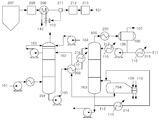
도 2는 본 발명에 따른 이산화탄소 포집공정도로서, 이산화탄소 포집장치는 흡수탑(201), 열교환기(202), 탈거탑(203), 리보일러(204), 응축기(205), 리플럭스 드럼(206), 배열회수 열교환기(209), 유량조절기(210), 온도감지기(211), 리클레이머(214), 흡수제 주입기(215), 흡수제 예열용 열교환기(216), 응축액 예열용 열교환기(217) 등을 포함한다.2 is a carbon dioxide collection process according to the present invention, the carbon dioxide capture device is an
흡수탑(201)으로 배기가스(101)와 흡수제(102)가 공급된다. 배기가스(101)는 이산화탄소를 포함한 연소배기가스이다. 흡수제(102)로는 특별히 제한되지 않고, 예를 들어 아민계, 아미노산염, 무기염류 용액, 암모니아수 및 이온염용액 등을 단독 또는 혼합하여 사용할 수 있다. 이때 흡수제(102)는 1 내지 50 부피 분율 범위의 수용액으로 이용되는 것이 좋다.The
흡수탑(201)에서 흡수제(102)와 배기가스(101)는 향류 접촉된다. 흡수제(102)는 배기가스(101) 중에 포함된 이산화탄소를 흡수하여 이산화탄소 포화 흡수제(105)를 생성한다. 배기가스(101) 중 흡수제(102)와 반응하지 않은 질소, 산소 등 미반응 가스는 흡수탑(201) 상부를 통해 배출된다. 흡수탑(201)의 운전온도는 흡수제(102)의 종류에 따라 달라질 수 있으며, 예를 들어 흡수탑(201)의 운전 온도는 40℃ 내지 60℃의 범위로 유지될 수 있다.In the
포화 흡수제(105)는 펌프에 의해 이송되고, 열교환기(202)에 의해 예열된 상태로 탈거탑(203) 상부로 주입된다. 탈거탑(203) 상부로 주입된 포화 흡수제(105)는 탈거탑(203)의 하부로 이동하면서 리보일러(204)에서 공급되는 열 에너지에 의하여 이산화탄소가 탈거되고 흡수제가 재생된다.The saturated absorbent 105 is conveyed by the pump and injected into the
이산화탄소와 배출수증기가 혼합된 혼합가스(106)는 응축기(205)와 리플럭스 드럼(206)을 거치면서, 응축수(108)와 이산화탄소(107)로 분리된다. 이산화탄소(107)는 회수 공정 또는 처리 공정으로 이송되어 저장 또는 용도에 따라 사용되고, 응축수(108)는 탈거탑(203)으로 공급된다.The mixed
재생된 흡수제(102)는 펌프에 의해 열교환기(202)를 거쳐 흡수탑(201) 상부로 공급된다. 재생된 흡수제 중 일부의 흡수제(112)는 리클레이머(214)로 보내지고, 여기에서 흡수제에 포함되어 있는 불순물을 가열하여 분리한다.The regenerated absorbent 102 is supplied to the upper portion of the
한편, 발전소 보일러(207)에서 배출되는 배기가스 중 질소 성분을 제거하기 위해, 절탄기(208)와 공기예열기(213) 사이에 배연탈질설비(212)가 설치된다.On the other hand, in order to remove the nitrogen component of the exhaust gas discharged from the
본 발명에서는 보일러(207)의 절탄기(208)와 배연탈질설비(212) 사이에 배열회수 열교환기(209)를 설치함으로써, 탈질설비(212)로 유입되는 배기가스의 반응온도를 조절하여 탈질 촉매의 탈질성능을 높이는 동시에, 배기가스의 열에너지를 회수하여 이산화탄소 포집공정의 탈거에너지로 이용하는 것을 특징으로 한다.In the present invention, by installing the heat
배열회수 열교환기(209)에는 유량조절기(210)가 설치되는 것이 바람직한데, 이 유량조절기(210)는 배열회수 열교환기(209)로 들어가는 물의 양을 조절함으로써, 배연탈질설비(212)로 유입되는 배기가스의 온도를 조절하여 배연탈질설비(212)의 탈질 성능을 유지함과 동시에, 회수되는 열량을 제어할 수 있다.The heat recovery heat exchanger (209) is preferably provided with a flow regulator 210, the flow regulator 210 by adjusting the amount of water entering the heat recovery heat exchanger (209), inlet to the flue gas denitrification facility (212). By controlling the temperature of the exhaust gas, the denitrification performance of the flue
또한, 배열회수 열교환기(209)와 배연탈질설비(212) 사이에는 온도감지기(211)가 설치되고, 이 온도감지기(211)는 유량조절기(210)와 연계되는 것이 바람직하다. 발전소의 출력변화에 따라 변하는 배연탈질설비(212) 전단의 배기가스의 온도를 온도감지기(211)를 통해 감지하여 적절한 배연탈질설비(212)의 촉매 반응온도에 맞추도록, 배열회수 열교환기(209)로 들어가는 물의 양을 유량조절기(210)를 통해 제어하여 추출 열량을 결정할 수 있다.In addition, a
배열회수 열교환기(209)를 통해 회수된 배기가스의 열은 수증기(110)의 형태로 리보일러(204) 등의 열원으로 공급되며, 배연탈질설비(212)에 의해 질소 성분이 제거된 배기가스(101)는 흡수탑(201)으로 공급된다.The heat of the exhaust gas recovered through the heat
리보일러(204)에 공급되는 열원으로는 배열회수 열교환기(209)를 통해 발생된 수증기(110) 및/또는 발전소의 고압, 중압, 저압 스팀 터빈으로부터의 수증기(109)를 이용할 수 있는데, 배열회수 열교환기(209)에서 회수된 열량만으로 이산화탄소와 흡수제를 분리하기에 부족한 열량은 발전소 고압, 중압, 저압 터빈으로부터 스팀을 축출하여 보충할 수 있다.As a heat source supplied to the
이와 같이, 리보일러(204)에 스팀을 공급하는 방법은 배열회수 열교환기(209)에서 회수된 스팀과 발전소 고압, 중압, 저압 터빈으로부터 회수한 스팀을 독립적으로 또는 혼합하여 공급할 수 있다. 즉, 배열회수 열교환기(209)를 통해 발생된 수증기(110)를 스팀터빈으로부터 추출된 수증기(109)와 혼합하여 리보일러(204)에 주입할 수 있고, 터빈 수증기(109)와는 별도로 리보일러(204)에 주입할 수 있다.As described above, in the method of supplying steam to the
한편, 배열회수 열교환기(209)를 통해 발생된 수증기(110)는 리보일러(204)의 열원뿐만 아니라, 리클레이머(214), 흡수제 주입기(215), 흡수제 예열용 열교환기(216), 응축액 예열용 열교환기(217)의 열원으로도 사용될 수 있다.Meanwhile, the
구체적으로, 배열회수 열교환기(209)로부터 회수된 열은 불순물 제거를 위한 리클레이머(214)의 열원으로 공급됨으로써, 탈거탑(203)으로 재순환되는 재생 흡수제(112)에 포함되어 있는 불순물을 가열하여 제거하는데 사용될 수 있다.Specifically, the heat recovered from the heat
또한, 배열회수 열교환기(209)로부터 회수된 열은 흡수액 주입장치(215)의 열원으로 공급됨으로써, 탈거탑(203)으로 공급되는 흡수제 보충분(111)을 용해하는데 사용될 수 있다.In addition, heat recovered from the heat
또한, 배열회수 열교환기(209)로부터 회수된 열은 흡수탑(201)과 탈거탑(203) 사이에 설치되는 흡수제 예열용 열교환기(216)의 열원으로 공급됨으로써, 이산화탄소로 포화되어 탈거탑(203)으로 이송되는 포화 흡수제(105)을 예열하는데 사용될 수 있다.In addition, the heat recovered from the heat
또한, 배열회수 열교환기(209)로부터 회수된 열은 응축액 예열용 열교환기(217)의 열원으로 공급됨으로써, 리플럭스 드럼(206)으로부터 회수되어 탈거탑(203)으로 공급되는 응축액을 가열하는데 사용될 수 있다.
In addition, the heat recovered from the heat
101: 배기가스
102: 흡수제/ 재생 흡수제
103: 세척수
104: 보충수
105: 이산화탄소 포화 흡수제
106: 이산화탄소와 수증기 혼합가스
107: 이산화탄소
108: 응축수
109: 터빈 수증기
110: 배기가스 열회수 수증기
111: 보충 흡수제
112: 불순물 제거용 재생흡수제
201: 흡수탑
202: 열교환기
203: 탈거탑
204: 리보일러
205: 응축기
206: 리플럭스 드럼
207: 보일러
208: 절탄기
209: 배열회수 열교환기
210: 유량조절기
211: 온도감지기
212: 배연탈질설비
213: 공기예열기
214: 리클레이머
215: 흡수제 주입기
216: 흡수제 예열용 열교환기
217: 응축액 예열용 열교환기101: exhaust gas
102: absorbent / regenerated absorbent
103: washing water
104: replenishment
105: carbon dioxide saturated absorbent
106: carbon dioxide and water vapor mixed gas
107: carbon dioxide
108: condensate
109: turbine steam
110: exhaust gas heat recovery steam
111: supplemental absorbent
112: regeneration absorbent for removing impurities
201: absorption tower
202: heat exchanger
203: stripping tower
204: reboiler
205: condenser
206: reflux drum
207: boiler
208: cutter
209: heat recovery heat exchanger
210: flow controller
211: temperature sensor
212: flue gas denitrification system
213: air preheater
214: reclaimer
215: absorbent injector
216: heat exchanger for absorbent preheating
217: heat exchanger for condensate preheating
Claims (18)
흡수탑과 연결되고 흡수제의 재생이 이루어지는 탈거탑;
탈거탑과 연결되고 흡수제의 재생에 필요한 열원을 공급하는 리보일러; 및
발전소 보일러의 절탄기와 배연탈질설비 사이에 설치되어 배기가스의 열을 회수하고, 리보일러와 연결되어 회수한 열을 리보일러의 열원으로 공급하는 배열회수 열교환기를 포함하는 이산화탄소 포집장치.
An absorption tower in which carbon dioxide is absorbed using an absorbent;
A stripping column connected to the absorption tower and configured to regenerate the absorbent;
A reboiler connected to the stripping column and supplying a heat source necessary for regeneration of the absorbent; And
A carbon dioxide capture device installed between a coal firer and a flue gas denitrification facility of a power plant boiler to recover heat from exhaust gas and supply heat recovered from a reboiler to a heat source of the reboiler.
배열회수 열교환기와 연결되어 배열회수 열교환기로 들어가는 물의 양을 조절함으로써, 배기가스의 온도를 조절하고 회수되는 열량을 제어하는 유량조절기를 추가로 포함하는 이산화탄소 포집장치.
The method of claim 1,
And a flow regulator for controlling the temperature of the exhaust gas and controlling the amount of heat recovered by controlling the amount of water that is connected to the heat recovery heat exchanger to enter the heat recovery heat exchanger.
배열회수 열교환기와 배연탈질설비 사이에 설치되어 배기가스의 온도를 감지하고, 유량조절기와 연계되는 온도감지기를 추가로 포함하는 이산화탄소 포집장치.
The method of claim 2,
Installed between the heat recovery heat exchanger and the flue gas denitrification equipment to detect the temperature of the exhaust gas, and further comprising a temperature sensor associated with the flow regulator.
탈거탑과 리보일러에 사이에 설치되고 재생 흡수제를 가열하여 불순물을 분리하며, 배열회수 열교환기와 연결되어 열원을 공급받는 리클레이머를 추가로 포함하는 이산화탄소 포집장치.
The method of claim 1,
And a reclaimer installed between the stripping column and the reboiler, to separate impurities by heating a regenerative absorbent, and further comprising a reclaimer connected to a heat recovery heat exchanger to receive a heat source.
탈거탑과 연결되어 탈거탑에 공급되는 흡수제 보충분을 용해하고, 배열회수 열교환기와 연결되어 열원을 공급받는 흡수제 주입기를 추가로 포함하는 이산화탄소 포집장치.
The method of claim 1,
And a sorbent injector connected to the stripping column to dissolve the absorbent supplement supplied to the stripping column and connected to the heat recovery heat exchanger to receive a heat source.
흡수탑과 탈거탑 사이에 설치되어 탈거탑으로 이송되는 포화 흡수제를 예열하고, 배열회수 열교환기와 연결되어 열원을 공급받는 흡수제 예열용 열교환기를 추가로 포함하는 이산화탄소 포집장치.
The method of claim 1,
A carbon dioxide capture device is installed between the absorption tower and the stripping column to preheat the saturated absorbent to be transferred to the stripping column, and further comprising an absorber preheating heat exchanger connected to the heat recovery heat exchanger to receive a heat source.
탈거탑과 연결되어 탈거탑으로 유입되는 응축액을 가열하고, 배열회수 열교환기와 연결되어 열원을 공급받는 응축액 예열용 열교환기를 추가로 포함하는 이산화탄소 포집장치.
The method of claim 1,
A carbon dioxide capture device is further connected to the stripping column to heat the condensate flowing into the stripping column, and further comprising a heat exchanger for preheating the condensate is connected to the heat recovery heat exchanger receives a heat source.
리보일러는 발전소 터빈과도 연결되어 터빈으로부터 열원을 선택적으로 공급받는 것을 특징으로 하는 이산화탄소 포집장치.
The method of claim 1,
The reboiler is also connected to the power plant turbine is a carbon dioxide capture device, characterized in that selectively receives a heat source from the turbine.
흡수제는 아민계, 아미노산염, 무기염계 용액, 암모니아수 또는 금속 이온염 용액 중에서 선택되는 1종 이상인 것을 특징으로 하는 이산화탄소 포집장치.
The method of claim 1,
Absorbent is a carbon dioxide capture device, characterized in that at least one selected from amine, amino acid salt, inorganic salt solution, ammonia water or metal ion salt solution.
발전소 보일러의 절탄기와 배연탈질설비 사이에 설치된 배열회수 열교환기를 통해 배기가스의 열을 회수하는 단계;
회수된 열을 탈거탑과 연결된 리보일러의 열원으로 공급하는 단계; 및
리보일러의 열원을 이용하여 탈거탑에서 흡수제를 재생하는 단계를 포함하는 이산화탄소 포집방법.
Absorbing carbon dioxide using an absorbent in the absorption tower;
Recovering heat of the exhaust gas through a heat recovery heat exchanger installed between the coal firer and the flue gas denitrification facility of the power plant boiler;
Supplying the recovered heat to a heat source of the reboiler connected to the stripping column; And
A method for capturing carbon dioxide comprising regenerating an absorbent in a stripping column using a heat source of the reboiler.
배열회수 열교환기와 연결된 유량조절기를 이용하여 배열회수 열교환기로 들어가는 물의 양을 조절함으로써, 배연탈질설비로 유입되는 배기가스의 온도를 조절하고 회수되는 열량을 제어하는 단계를 추가로 포함하는 이산화탄소 포집방법.
The method of claim 10,
And controlling the temperature of the exhaust gas flowing into the flue gas denitrification system and controlling the amount of heat recovered by controlling the amount of water entering the heat recovery heat exchanger using a flow controller connected to the heat recovery heat exchanger.
배열회수 열교환기와 배연탈질설비 사이에 설치된 온도감지기를 이용하여 배기가스의 온도를 감지하면서, 온도감지기와 연계된 유량조절기를 제어하는 단계를 추가로 포함하는 이산화탄소 포집방법.
The method of claim 11,
And detecting the temperature of the exhaust gas by using a temperature sensor installed between the heat recovery heat exchanger and the flue gas denitrification system, and controlling the flow regulator associated with the temperature sensor.
배열회수 열교환기로부터 회수된 열을 탈거탑과 리보일러에 사이에 설치된 리클레이머의 열원으로 사용하여 재생 흡수제의 불순물을 분리하는 단계를 추가로 포함하는 이산화탄소 포집방법.
The method of claim 10,
And collecting the impurities of the regeneration absorbent by using the heat recovered from the heat recovery heat exchanger as a heat source of the reclaimer installed between the stripping column and the reboiler.
배열회수 열교환기로부터 회수된 열을 탈거탑과 연결된 흡수제 주입기의 열원으로 사용하여 탈거탑에 공급되는 흡수제 보충분을 용해하는 단계를 추가로 포함하는 이산화탄소 포집방법.
The method of claim 10,
And dissolving the absorbent supplement supplied to the stripping column by using the heat recovered from the heat recovery heat exchanger as a heat source of the absorber injector connected to the stripping column.
배열회수 열교환기로부터 회수된 열을 흡수탑과 탈거탑 사이에 설치된 열교환기의 열원으로 사용하여 탈거탑으로 이송되는 포화 흡수제를 예열하는 단계를 추가로 포함하는 이산화탄소 포집방법.
The method of claim 10,
And preheating the saturated absorbent transferred to the stripping column by using the heat recovered from the heat recovery heat exchanger as a heat source of the heat exchanger installed between the absorption tower and the stripping column.
배열회수 열교환기로부터 회수된 열을 탈거탑과 연결된 열교환기의 열원으로 사용하여 탈거탑으로 유입되는 응축액을 가열하는 단계를 추가로 포함하는 이산화탄소 포집방법.
The method of claim 10,
And heating the condensate introduced into the stripping column by using the heat recovered from the heat recovery heat exchanger as a heat source of the heat exchanger connected to the stripping column.
발전소 터빈의 열원을 선택적으로 리보일러의 열원으로 사용하는 것을 특징으로 하는 이산화탄소 포집방법.
The method of claim 10,
A method of capturing carbon dioxide, characterized by selectively using a heat source of a power plant turbine as a heat source of a reboiler.
흡수제는 아민계, 아미노산염, 무기염계 용액, 암모니아수 또는 금속 이온염 용액 중에서 선택되는 1종 이상인 것을 특징으로 하는 이산화탄소 포집방법.The method of claim 10,
Absorbent is a carbon dioxide capture method, characterized in that at least one selected from amine, amino acid salt, inorganic salt solution, ammonia water or metal ion salt solution.
Priority Applications (1)
| Application Number | Priority Date | Filing Date | Title |
|---|---|---|---|
| KR1020110086271A KR101746235B1 (en) | 2011-08-29 | 2011-08-29 | Energy saving method and apparatus for carbon dioxide capture in power plant |
Applications Claiming Priority (1)
| Application Number | Priority Date | Filing Date | Title |
|---|---|---|---|
| KR1020110086271A KR101746235B1 (en) | 2011-08-29 | 2011-08-29 | Energy saving method and apparatus for carbon dioxide capture in power plant |
Publications (2)
| Publication Number | Publication Date |
|---|---|
| KR20130023484A true KR20130023484A (en) | 2013-03-08 |
| KR101746235B1 KR101746235B1 (en) | 2017-06-13 |
Family
ID=48175707
Family Applications (1)
| Application Number | Title | Priority Date | Filing Date |
|---|---|---|---|
| KR1020110086271A KR101746235B1 (en) | 2011-08-29 | 2011-08-29 | Energy saving method and apparatus for carbon dioxide capture in power plant |
Country Status (1)
| Country | Link |
|---|---|
| KR (1) | KR101746235B1 (en) |
Cited By (12)
| Publication number | Priority date | Publication date | Assignee | Title |
|---|---|---|---|---|
| KR20150024190A (en) * | 2013-08-26 | 2015-03-06 | 한국전력공사 | System for solvent scrubbing acid gas by improvement of stripper process flow and method for solvent scrubbing acid gas using thereof |
| WO2015080324A1 (en) * | 2013-11-27 | 2015-06-04 | 한국에너지기술연구원 | Energy-saving acidic gas capture system and method using separated water |
| WO2015083866A1 (en) * | 2013-12-04 | 2015-06-11 | 한국에너지기술연구원 | Energy-saving acid gas capture system and method |
| WO2015083865A1 (en) * | 2013-12-04 | 2015-06-11 | 한국에너지기술연구원 | System and method for separation and recovery of acid gas |
| KR20160016144A (en) | 2014-08-04 | 2016-02-15 | 한국전력공사 | System for collecting acid gas and method for collecting the same |
| KR20190069357A (en) * | 2019-06-04 | 2019-06-19 | 재단법인 포항산업과학연구원 | Method for preventing vaporization of absorbent in the CO2 capture process |
| KR20190074048A (en) * | 2017-12-19 | 2019-06-27 | 한국에너지기술연구원 | Waste heat application method applicable to waste heat generation plant |
| CN110354644A (en) * | 2018-04-10 | 2019-10-22 | 天津科技大学 | A kind of efficient butyl acetate waste gas absorption and desorption apparatus |
| CN115212699A (en) * | 2022-08-15 | 2022-10-21 | 中国海洋石油集团有限公司 | Oxygen-enriched scorching regeneration and heat comprehensive utilization process and system |
| CN115350574A (en) * | 2022-08-03 | 2022-11-18 | 大连理工大学 | Gas thermal power energy recovery and carbon capture comprehensive utilization method and device |
| CN115463516A (en) * | 2022-07-22 | 2022-12-13 | 国家能源集团新能源技术研究院有限公司 | System and method for using flue gas waste heat for carbon capture regeneration |
| KR102533169B1 (en) * | 2022-04-12 | 2023-05-15 | 김성주 | Carbon dioxide capture device with improved energy efficiency |
Family Cites Families (3)
| Publication number | Priority date | Publication date | Assignee | Title |
|---|---|---|---|---|
| JP4795991B2 (en) | 2007-02-27 | 2011-10-19 | 三菱重工業株式会社 | CO2 recovery device and solid content extraction method in CO2 recovery device |
| JP5558036B2 (en) * | 2008-09-04 | 2014-07-23 | 株式会社東芝 | Carbon dioxide recovery steam power generation system |
| JP2010235395A (en) | 2009-03-31 | 2010-10-21 | Hitachi Ltd | Apparatus for recovering carbon dioxide, and thermal power system with apparatus for recovering carbon dioxide |
-
2011
- 2011-08-29 KR KR1020110086271A patent/KR101746235B1/en active IP Right Grant
Cited By (16)
| Publication number | Priority date | Publication date | Assignee | Title |
|---|---|---|---|---|
| KR20150024190A (en) * | 2013-08-26 | 2015-03-06 | 한국전력공사 | System for solvent scrubbing acid gas by improvement of stripper process flow and method for solvent scrubbing acid gas using thereof |
| WO2015080324A1 (en) * | 2013-11-27 | 2015-06-04 | 한국에너지기술연구원 | Energy-saving acidic gas capture system and method using separated water |
| US9579599B2 (en) | 2013-11-27 | 2017-02-28 | Korea Institute Of Energy Research | Energy-saving system and method of capturing acidic gas by using separated water |
| WO2015083866A1 (en) * | 2013-12-04 | 2015-06-11 | 한국에너지기술연구원 | Energy-saving acid gas capture system and method |
| WO2015083865A1 (en) * | 2013-12-04 | 2015-06-11 | 한국에너지기술연구원 | System and method for separation and recovery of acid gas |
| US9757680B2 (en) | 2013-12-04 | 2017-09-12 | Korea Institute Of Energy Research | System and method for separation and recovery of acid gas |
| US9956518B2 (en) | 2013-12-04 | 2018-05-01 | Korea Institute Of Energy Research | Energy-saving acid gas capture system and method |
| KR20160016144A (en) | 2014-08-04 | 2016-02-15 | 한국전력공사 | System for collecting acid gas and method for collecting the same |
| KR20190074048A (en) * | 2017-12-19 | 2019-06-27 | 한국에너지기술연구원 | Waste heat application method applicable to waste heat generation plant |
| CN110354644A (en) * | 2018-04-10 | 2019-10-22 | 天津科技大学 | A kind of efficient butyl acetate waste gas absorption and desorption apparatus |
| KR20190069357A (en) * | 2019-06-04 | 2019-06-19 | 재단법인 포항산업과학연구원 | Method for preventing vaporization of absorbent in the CO2 capture process |
| KR102533169B1 (en) * | 2022-04-12 | 2023-05-15 | 김성주 | Carbon dioxide capture device with improved energy efficiency |
| CN115463516A (en) * | 2022-07-22 | 2022-12-13 | 国家能源集团新能源技术研究院有限公司 | System and method for using flue gas waste heat for carbon capture regeneration |
| CN115350574A (en) * | 2022-08-03 | 2022-11-18 | 大连理工大学 | Gas thermal power energy recovery and carbon capture comprehensive utilization method and device |
| CN115350574B (en) * | 2022-08-03 | 2023-08-04 | 大连理工大学 | Gas heat function recovery and carbon capture comprehensive utilization method and device |
| CN115212699A (en) * | 2022-08-15 | 2022-10-21 | 中国海洋石油集团有限公司 | Oxygen-enriched scorching regeneration and heat comprehensive utilization process and system |
Also Published As
| Publication number | Publication date |
|---|---|
| KR101746235B1 (en) | 2017-06-13 |
Similar Documents
| Publication | Publication Date | Title |
|---|---|---|
| KR101746235B1 (en) | Energy saving method and apparatus for carbon dioxide capture in power plant | |
| CA2811261C (en) | Removal of non-volatiles from ammonia-based co2-absorbent solution | |
| US20130327025A1 (en) | Combustion exhaust gas treatment system and method of treating combustion exhaust gas | |
| EP2230000B1 (en) | Flue gas treatment system and method using ammonia solution | |
| US9138677B2 (en) | Ammonia stripper for a carbon capture system for reduction of energy consumption | |
| EP2823876B1 (en) | System for chemically absorbing carbon dioxide in combustion exhaust gas | |
| JP2013059726A (en) | Co2 recovery device and co2 recovery method | |
| JP5738137B2 (en) | CO2 recovery apparatus and CO2 recovery method | |
| EP2726179B1 (en) | Low pressure steam pre-heaters for gas purification systems and processes of use | |
| KR20130046546A (en) | Acidic gas capturing apparatus and method capable of controlling acidic gas absorption quantity | |
| KR20150004562A (en) | Carbon dioxide capture device | |
| JP5237204B2 (en) | CO2 recovery apparatus and method | |
| JP2011000528A (en) | Co2 recovering device and co2 recovering method | |
| JP2011005367A (en) | Co2 recovering apparatus and method | |
| JP2011005368A (en) | Co2 recovering apparatus and method | |
| KR101036651B1 (en) | Recovery method of carbon dioxide from off gas by non used waste heat utilization | |
| AU2015200530B2 (en) | Removal of non-volatiles from ammonia-based CO2-absorbent solution | |
| KR20180024464A (en) | Method for collecting acid gas using demineralized water |
Legal Events
| Date | Code | Title | Description |
|---|---|---|---|
| A201 | Request for examination | ||
| E902 | Notification of reason for refusal | ||
| E701 | Decision to grant or registration of patent right | ||
| GRNT | Written decision to grant |