EP2268211B1 - Outil d'accès minimal - Google Patents
Outil d'accès minimal Download PDFInfo
- Publication number
- EP2268211B1 EP2268211B1 EP09729763.4A EP09729763A EP2268211B1 EP 2268211 B1 EP2268211 B1 EP 2268211B1 EP 09729763 A EP09729763 A EP 09729763A EP 2268211 B1 EP2268211 B1 EP 2268211B1
- Authority
- EP
- European Patent Office
- Prior art keywords
- user
- tool
- joint
- pitch
- yaw
- Prior art date
- Legal status (The legal status is an assumption and is not a legal conclusion. Google has not performed a legal analysis and makes no representation as to the accuracy of the status listed.)
- Active
Links
Images


Classifications
-
- A—HUMAN NECESSITIES
- A61—MEDICAL OR VETERINARY SCIENCE; HYGIENE
- A61B—DIAGNOSIS; SURGERY; IDENTIFICATION
- A61B17/00—Surgical instruments, devices or methods, e.g. tourniquets
- A61B17/28—Surgical forceps
- A61B17/29—Forceps for use in minimally invasive surgery
- A61B17/2909—Handles
-
- A—HUMAN NECESSITIES
- A61—MEDICAL OR VETERINARY SCIENCE; HYGIENE
- A61B—DIAGNOSIS; SURGERY; IDENTIFICATION
- A61B34/00—Computer-aided surgery; Manipulators or robots specially adapted for use in surgery
- A61B34/70—Manipulators specially adapted for use in surgery
-
- A—HUMAN NECESSITIES
- A61—MEDICAL OR VETERINARY SCIENCE; HYGIENE
- A61B—DIAGNOSIS; SURGERY; IDENTIFICATION
- A61B34/00—Computer-aided surgery; Manipulators or robots specially adapted for use in surgery
- A61B34/70—Manipulators specially adapted for use in surgery
- A61B34/71—Manipulators operated by drive cable mechanisms
-
- A—HUMAN NECESSITIES
- A61—MEDICAL OR VETERINARY SCIENCE; HYGIENE
- A61B—DIAGNOSIS; SURGERY; IDENTIFICATION
- A61B34/00—Computer-aided surgery; Manipulators or robots specially adapted for use in surgery
- A61B34/70—Manipulators specially adapted for use in surgery
- A61B34/75—Manipulators having means for prevention or compensation of hand tremors
-
- A—HUMAN NECESSITIES
- A61—MEDICAL OR VETERINARY SCIENCE; HYGIENE
- A61B—DIAGNOSIS; SURGERY; IDENTIFICATION
- A61B34/00—Computer-aided surgery; Manipulators or robots specially adapted for use in surgery
- A61B34/70—Manipulators specially adapted for use in surgery
- A61B34/77—Manipulators with motion or force scaling
-
- A—HUMAN NECESSITIES
- A61—MEDICAL OR VETERINARY SCIENCE; HYGIENE
- A61B—DIAGNOSIS; SURGERY; IDENTIFICATION
- A61B17/00—Surgical instruments, devices or methods, e.g. tourniquets
- A61B17/00234—Surgical instruments, devices or methods, e.g. tourniquets for minimally invasive surgery
- A61B2017/00292—Surgical instruments, devices or methods, e.g. tourniquets for minimally invasive surgery mounted on or guided by flexible, e.g. catheter-like, means
- A61B2017/003—Steerable
- A61B2017/00318—Steering mechanisms
- A61B2017/00323—Cables or rods
-
- A—HUMAN NECESSITIES
- A61—MEDICAL OR VETERINARY SCIENCE; HYGIENE
- A61B—DIAGNOSIS; SURGERY; IDENTIFICATION
- A61B17/00—Surgical instruments, devices or methods, e.g. tourniquets
- A61B2017/0042—Surgical instruments, devices or methods, e.g. tourniquets with special provisions for gripping
- A61B2017/00424—Surgical instruments, devices or methods, e.g. tourniquets with special provisions for gripping ergonomic, e.g. fitting in fist
-
- A—HUMAN NECESSITIES
- A61—MEDICAL OR VETERINARY SCIENCE; HYGIENE
- A61B—DIAGNOSIS; SURGERY; IDENTIFICATION
- A61B17/00—Surgical instruments, devices or methods, e.g. tourniquets
- A61B2017/0042—Surgical instruments, devices or methods, e.g. tourniquets with special provisions for gripping
- A61B2017/00442—Surgical instruments, devices or methods, e.g. tourniquets with special provisions for gripping connectable to wrist or forearm
-
- A—HUMAN NECESSITIES
- A61—MEDICAL OR VETERINARY SCIENCE; HYGIENE
- A61B—DIAGNOSIS; SURGERY; IDENTIFICATION
- A61B17/00—Surgical instruments, devices or methods, e.g. tourniquets
- A61B2017/0046—Surgical instruments, devices or methods, e.g. tourniquets with a releasable handle; with handle and operating part separable
- A61B2017/00464—Surgical instruments, devices or methods, e.g. tourniquets with a releasable handle; with handle and operating part separable for use with different instruments
-
- A—HUMAN NECESSITIES
- A61—MEDICAL OR VETERINARY SCIENCE; HYGIENE
- A61B—DIAGNOSIS; SURGERY; IDENTIFICATION
- A61B17/00—Surgical instruments, devices or methods, e.g. tourniquets
- A61B17/28—Surgical forceps
- A61B17/29—Forceps for use in minimally invasive surgery
- A61B17/2909—Handles
- A61B2017/2912—Handles transmission of forces to actuating rod or piston
- A61B2017/2913—Handles transmission of forces to actuating rod or piston cams or guiding means
- A61B2017/2917—Handles transmission of forces to actuating rod or piston cams or guiding means with flexible part
-
- A—HUMAN NECESSITIES
- A61—MEDICAL OR VETERINARY SCIENCE; HYGIENE
- A61B—DIAGNOSIS; SURGERY; IDENTIFICATION
- A61B17/00—Surgical instruments, devices or methods, e.g. tourniquets
- A61B17/28—Surgical forceps
- A61B17/29—Forceps for use in minimally invasive surgery
- A61B2017/2926—Details of heads or jaws
- A61B2017/2927—Details of heads or jaws the angular position of the head being adjustable with respect to the shaft
- A61B2017/2929—Details of heads or jaws the angular position of the head being adjustable with respect to the shaft with a head rotatable about the longitudinal axis of the shaft
-
- A—HUMAN NECESSITIES
- A61—MEDICAL OR VETERINARY SCIENCE; HYGIENE
- A61B—DIAGNOSIS; SURGERY; IDENTIFICATION
- A61B17/00—Surgical instruments, devices or methods, e.g. tourniquets
- A61B17/28—Surgical forceps
- A61B17/29—Forceps for use in minimally invasive surgery
- A61B2017/2926—Details of heads or jaws
- A61B2017/2931—Details of heads or jaws with releasable head
-
- A—HUMAN NECESSITIES
- A61—MEDICAL OR VETERINARY SCIENCE; HYGIENE
- A61B—DIAGNOSIS; SURGERY; IDENTIFICATION
- A61B17/00—Surgical instruments, devices or methods, e.g. tourniquets
- A61B17/28—Surgical forceps
- A61B17/29—Forceps for use in minimally invasive surgery
- A61B2017/2926—Details of heads or jaws
- A61B2017/2932—Transmission of forces to jaw members
- A61B2017/2933—Transmission of forces to jaw members camming or guiding means
- A61B2017/2937—Transmission of forces to jaw members camming or guiding means with flexible part
-
- A—HUMAN NECESSITIES
- A61—MEDICAL OR VETERINARY SCIENCE; HYGIENE
- A61B—DIAGNOSIS; SURGERY; IDENTIFICATION
- A61B17/00—Surgical instruments, devices or methods, e.g. tourniquets
- A61B17/28—Surgical forceps
- A61B17/29—Forceps for use in minimally invasive surgery
- A61B2017/2926—Details of heads or jaws
- A61B2017/2932—Transmission of forces to jaw members
- A61B2017/2939—Details of linkages or pivot points
-
- A—HUMAN NECESSITIES
- A61—MEDICAL OR VETERINARY SCIENCE; HYGIENE
- A61B—DIAGNOSIS; SURGERY; IDENTIFICATION
- A61B17/00—Surgical instruments, devices or methods, e.g. tourniquets
- A61B17/28—Surgical forceps
- A61B17/29—Forceps for use in minimally invasive surgery
- A61B2017/2926—Details of heads or jaws
- A61B2017/2932—Transmission of forces to jaw members
- A61B2017/2944—Translation of jaw members
-
- A—HUMAN NECESSITIES
- A61—MEDICAL OR VETERINARY SCIENCE; HYGIENE
- A61B—DIAGNOSIS; SURGERY; IDENTIFICATION
- A61B34/00—Computer-aided surgery; Manipulators or robots specially adapted for use in surgery
- A61B34/30—Surgical robots
- A61B2034/305—Details of wrist mechanisms at distal ends of robotic arms
- A61B2034/306—Wrists with multiple vertebrae
Definitions
- This invention relates to a minimal access tool, such as for surgery, endoscopy, or other interventions.
- MIS Minimally invasive surgical
- other minimal access procedures are increasing in frequency and becoming more complex, thus demanding improvements in technology to meet the needs of surgeons.
- MIS minimal invasive surgical
- In these procedures generally thin tools are inserted into the body through ports.
- Motion input from the user, such as a surgeon is transferred via the tool to the motion of a manipulator attached to the tool's tip inside the patient's body.
- This arrangement is used to carry out an externally controlled operation within the body without making large incisions.
- MIS tools range from simple scissor-like tools to complex robotic systems.
- US 5908436 A discloses a medical handling device, in particular for endoscopic applications, has a distally arranged medical instrument, a proximally arranged handle which has a grip part that can be gripped with the hand, and further a shaft part arranged between instrument and handle. It is proposed that the grip part gripped by a human hand can pivot relative to the shaft part about both the volar flexion axis and the dorsal flexion axis of the wrist, with no change occurring thereby in the position of the shaft part.
- the present invention provides a high-dexterity, multi-DoF, minimal access tool capable of intuitive actuation for use in MIS, endoscopy, or other interventions.
- a tool in accordance with the present invention is designated generally by reference numeral 10 and may provide the following functionality.
- six DoF may be provided at an end effector 12, such as a tool tip manipulator, to provide complete motion control in the three translational directions and three rotational directions.
- the end effector 12 may have an open/close capability for grasping, cutting, etc., depending on its use.
- Ergonomic and intuitive motion mapping may be provided from an input (i.e., a user's arm, hand, and fingers) to an output (i.e., the end effector 12), and the tool 10 may provide force feedback to allow the user to feel the amount of force exerted by the tool 10. Still further, the tool 10 may provide motion scaling between the input and output motions, and hand-tremor reduction to improve the precision in surgery. It should be noted that "DoF” and "motion” are used interchangeably in the description provided herein.
- the tool 10 according to the present invention may be purely mechanical with a minimal number of components and assembly steps, ensuring simplicity and cost-effective manufacturing.
- a mechanical hand-held tool 10 is illustrated, wherein the DoF of the end effector 12 may be controlled by their physiological analogs at the user's end 14. Intuitive input-output motion mapping for the tool 10 may be achieved when the DoF motions of the end effector 12 match those of the user's arm, hand, and fingers.
- the tool 10 includes a frame 18 arranged to be attached to the user's arm, typically the forearm, such as via an arm attachment member 20 or other means.
- the frame 18 may be generally rigid, and also may incorporate length and size adjustability features so as to accommodate users of varying sizes.
- the tool 10 further includes a tool shaft 22 having a proximal end 21 and a distal end 23, wherein the frame 18 may be connected to the shaft proximal end 21.
- the tool shaft 22 is configured to pass through a surgical port in the patient's body (not shown), such that the tool shaft 22 may be generally elongated and thin with a generally round cross-section, although the shaft 22 is not limited to this configuration.
- the tool shaft 22 may be generally rigid, or alternatively a flexible tool conduit such as one used in endoscopy may be used while retaining all other functionality.
- An input joint is connected to the frame 18 and arranged to receive the user's wrist motion input, wherein the input joint includes a virtual center-of-rotation (VC) mechanism 16 (best shown in FIGS. 9 , 12 , and 13 ) which provides a center of rotation that generally coincides with a wrist joint W of the user.
- the VC mechanism 16 creates a 2-DoF or 3-DoF joint with a virtual center-of-rotation located close to the user's own wrist W.
- a joint with a virtual center-of-rotation is one where no physical structure need exist at the virtual center-of-rotation.
- Such a joint should include a body that the user's hand can actuate, wherein this body is constrained by the VC mechanism 16 to move as if virtually pivoted at a point at the user's wrist by a 2-DoF universal or 3-DoF rotational joint.
- the user's hand can rotate freely in at least two directions relative to the user's forearm naturally about the user's wrist W. The natural motion of the user's arm is then replicated at the end effector 12 inside the patient's body.
- a traditional 2-DoF joint could be used for the input joint, as in U.S. Patent No. 7,147,650 .
- the center-of-rotation of the input joint in such cases coincides with the physical location of the joint, and hence can never be made to coincide with the user's wrist given the physical geometry/space constraints. Consequently, at the input the user would have to move his/her forearm, elbow, and shoulder along with the wrist to produce the output pitch and yaw motions at the end effector 12, which is cumbersome and non-intuitive.
- the center-of-rotation of the input joint 16 should generally coincide with the location of the user's wrist. This enables the user to move his/her wrist naturally and comfortably during operation, independent of forearm, elbow, and shoulder motions.
- the frame 18 gives structural integrity to the entire tool 10, providing a rigid connection between the arm attachment member 20 and the tool shaft 22, and also providing the reference ground for the VC mechanism 16.
- the frame 18 may be implemented in one of several ways. According to one non-limiting aspect of the present invention, a curved structure that does not interfere with the user's hand/fingers during wrist rotations may be provided, which may include a T-shaped or tubular cross-section to enhance structural rigidity. Also, as best illustrated in FIG. 9 , the VC mechanism 16 may include a first end or ground base 25 which is connected to or part of the frame 18.
- a second, input end of the VC mechanism 16 may comprise a floating member, such as a plate 26.
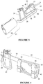
- the tool 10 may further comprise a handle 24 (also shown in FIGS. 3 and 4 ) mounted to the plate 26 to allow convenient grasping by a user's hand, wherein any wrist rotations of the user's hand are transmitted to the plate 26 via the handle 24.
- the handle 24 may include a soft covering comprised of a material such as rubber, and different types of grip tape, foam, or other materials may be used for comfort.
- the handle 24 may be of a pistol-grip type as depicted, or other handle shapes may be used including, but not limited to, scissor-like rings, a squeeze-ball grip design, or an ergonomic shape that conforms to a user's hand grip. Any shape of handle 24 may be used, provided it can be mounted to the floating plate 26. Alternatively, the handle 24 and the plate 26 may be embodied as a single component by simply extending the shape of the floating plate 26. It is also understood that the floating member 26 may take forms other than the plate depicted herein.
- the VC mechanism 16 may be covered with a baffle 30, such as for aesthetic reasons, and to contain an additional roll rotational DoF that may be provided by a 3-DoF VC mechanism 16 as described further below.
- the end effector 12 may be connected to the tool shaft distal end 23 via an output joint 32, wherein the output joint 32 is mechanically coupled to the VC mechanism input joint 16 to correlate motion of the VC mechanism 16 to motion of the output joint 32.
- the tool shaft 22 provides the reference ground for the end effector 12.
- a transmission system comprising cables 34 (best shown in FIGS. 5-10 ) connects the VC mechanism input joint 16 to the output joint 32 and end effector 12, thereby linking their motions.
- cables 34 (best shown in FIGS. 5-10 ) connects the VC mechanism input joint 16 to the output joint 32 and end effector 12, thereby linking their motions.
- the present invention is not limited to the use of cables 34, and that any type of mechanical transmission between the input joint 16 and the output joint 32 is fully contemplated.
- the dimensions and geometry of all components of the tool 10 according to the present invention may be chosen such that the wrist motion of the user's hand is replicated at the end effector 12 with any desired and adjustable scaling factor.
- FIG. 2a shows the three translation motions and roll rotation of the human forearm, the two rotational motions (pitch and yaw) of the human wrist, and the grasping motion of human hand.
- FIG. 2b shows the corresponding DoF of the tool 10 according to the present invention. These DoF include three translations and a roll rotation of the tool shaft 22, two wrist-like rotations (pitch and yaw), and a grasping motion of the end effector 12.
- a tool 10 as described herein that provides a one-to-one mapping between the human input DoF and the output DoF of the end effector 12.
- the 6 DoF of the arm and wrist, and the grasping action of the hand may be relayed successfully to the end effector 12. Because control of the motion of the end effector 12 happens with natural motion of the user's forearm, wrist, and hand, the tool 10 according to the present invention successfully provides multi-DoF motion with intuitive input-output motion mapping. Because the system may be purely mechanical, it intrinsically relays force feedback.
- the roll rotation at the end effector 12 is the consequence of forearm roll rotation only, as there is no roll rotation at the user's wrist with respect to the user's forearm. Since the frame 18 is secured to the user's forearm, any roll rotation of the forearm is transmitted entirely to the frame 18, the tool shaft 22, and ultimately to the end effector 12 when the output joint 32 is a 2-DoF joint. Thus, it is acceptable to have an input joint 16 that provides three rotational DoF (the desired yaw and pitch, and an additional roll). The roll is redundant because, in the above-described arrangement, any roll DoF of the input joint 16 cannot be actuated by the user's wrist motion.
- a spatial transmission mechanism may be used not only to transmit two rotational DoF (pitch and yaw) but all three rotational DoF (pitch, yaw, and roll).
- pitch and yaw rotational DoF
- yaw rotational DoF
- roll rotational DoF
- the present disclosure provides a method to translate the user's forearm's four DoF (3 translations and one roll rotation) to the corresponding DoF of the end effector 12 by providing a reference ground for the end effector 12 that is rigidly attached to the user's arm.
- the tool 10 described herein may be provided with a continuous rigid structure attached directly or indirectly to the user's arm.
- This continuous rigid structure may also incorporate a relatively long narrow feature to penetrate the patient's body.
- the tip of the long narrow feature which now is part of the continuous rigid structure, may provide a reference ground for the end effector 12.
- This ground and end effector 12 may be interconnected via an output joint 32.
- This continuous rigid structure also provides a reference ground for the VC mechanism 16 described above.
- the plate 26, which sees the user's motion inputs, may be connected to this ground via the VC mechanism input joint 16.
- the continuous rigid structure may effectively create a shared reference ground for the various mechanisms, sub-mechanisms, and joints in the tool 10 according to the present invention.
- This continuous rigid structure can include a single rigid body or several bodies connected rigidly to each other. These several rigid bodies may be detachable, re-attachable, and re-configurable.
- the continuous rigid structure may comprise the arm attachment member 20, the frame 18, and the tool shaft 22 (see FIG. 1 ).
- the arm attachment member 20 may be used to attach the continuous rigid structure to the forearm of the user.
- the end effector 12 may be attached to the continuous rigid structure at the tool shaft distal end 23 via an output joint 32.
- the end effector 12, the output joint 32, and a portion of the tool shaft 22 are generally in vivo, while the other components are generally in vitro.
- the implementation of the frame 18, the tool shaft 22, and the arm attachment member 20 dictates the general shape of the continuous rigid structure. Obviously, the geometries of these components and the overall continuous rigid structure can vary from that depicted herein and can be selected for right-hand or lefthand use.
- the end effector 12 may be made detachable so that the user may release and detach one end effector 12 and replace it with a different kind of end effector 12.
- the end effector 12 may be replaced while keeping the frame 18 attached to the user's forearm and the tool shaft 22 remaining attached to the frame 18. This allows the end effector 12 to be pulled out of the tool shaft 22 at a location outside the patient's body and be replaced by an end effector 12 with a different functionality during an operation, thus allowing the tool shaft 22 to remain in place while the end effector 12 is replaced.
- the end effector 12 and associated mechanisms may be disengaged utilizing a quick release or other mechanism and withdrawn through a hole in the frame 18 or tool shaft 22 without moving the tool shaft 22. This allows the user to change end effectors 12 while keeping the tool 10 inside of the patient.
- the arm attachment member 20 is provided to quickly and easily secure the user's forearm to the frame 18.
- the arm attachment member 20 may include flexible or rigid members to provide a secure interface between the forearm and the frame 18.
- the arm attachment member 20 may include flexible adjustable straps 36 that encircle the forearm and use a hook-and-loop arrangement, snap joints, buckles or other features for securing the arm attachment member 20 to the user's forearm.
- the arm attachment member 20 may also include a supporting shell-type structure 38 which may be made generally in the shape of a forearm (for example, half cone-shaped) to ensure comfort and correct attachment positioning.
- the shell structure 38 may be at least partially lined with a foam pad 40 or other suitable material to provide a comfortable interface between the user's forearm and the arm attachment member 20.
- the foam pad 40 may comprise a polyurethane open cell foam, although other types of soft gel and/or foam may also be used.
- the arm attachment member 20 may extend around approximately half of the forearm circumference. According to one non-limiting aspect of the present invention, the arm attachment member 20 may be integrated with the frame 18 for ease of manufacturing.
- the support shell structure 38 may extend partially or completely around the forearm. If the shell structure 38 extends partially around the forearm, other flexible or rigid components may be used to completely enclose and secure the forearm.
- the shell structure 38 can also extend around the entire circumference of the arm either continuously or in multiple sections. If the shell structure 38 encircles the forearm continuously, shape-morphing padding may be used to fit the forearm in place snugly. This padding could possibly be either passive or actuated by pressure, heat, or some other controllable shape-morphing structure. If the shell structure 38 encircles the forearm in sections, joints may be provided between each section.
- the present disclosure provides a method to relate the two wrist DoF to the corresponding two rotational DoF of the end effector 12.
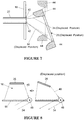
- This may be achieved using a master-slave, cable-based spatial transmission design, where the user actuates the master joint (input joint or VC mechanism 16) and the motion is transferred to the slave joint (output joint 32) via cables 34, and optionally cams (see, for example, FIG. 7 ) or pulleys (see, for example, FIG. 8 ).
- the two joints are coupled such that the motion at the output joint 32 is dependent on the input joint 16.
- the user input for actuating the input joint 16 comes from the rotation of the user's hand which happens about the user's wrist relative to the user's forearm.
- the two joints in question should have at least two rotational DoF (pitch and yaw) each.
- this structure also provides the ground for the two joints. Consequently, the two rotations produced at the end effector 12 are with respect to the user's forearm.
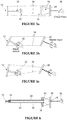
- a planar illustration of the transmission design, depicting one rotational DoF, is provided in FIG. 5 for the purpose of explanation.
- the present invention includes a spatial transmission design that transmits at least two wrist rotations (pitch and yaw) while utilizing 2-DoF or 3-DoF joints as the input 16 and output 32 joints.
- respective points on the floating plate 26 at the input joint 16 and the end effector 12 at the output joint 32 with similar orientation are connected (i.e., top to top, bottom to bottom, etc.) via cables 34, as schematically represented in FIG. 5 .
- This kind of connection ensures independent control of the two rotational DoF at the end effector 12 by corresponding rotations of the user's wrist.
- Rotation of the input joint 16 causes push and/or pull action to be transmitted from the floating plate 26 to the end effector 12 via cables 34 that may pass through the tool shaft 22 and attach to the output joint 32.
- corresponding points on the floating plate 26 and end effector 12 can be connected with either cables 34 or instead with rigid links (or push rods) with appropriate joints. It is also contemplated that the connection points could be reversed, e.g. top to bottom, bottom to top, to produce motion at the end effector 12 in a direction opposite the input motion at the floating plate 26 and the handle 24.
- FIG. 5c depicts motion scaling between the input and output joints 16, 32 which may be accomplished by varying the attachment points of the cables 34 between the end effector 12 (output joint 32) and the floating plate 26 (input joint 16).
- compliant and dampened joints may be used in the VC mechanism 16
- a compliant and dampened universal joint may be used for the output joint 32
- finite stiffness cables 34 may be used for the motion transmission system. All these flexible and dampening elements together may act as a low-pass filter, reducing the effects of high frequency input hand-tremors at the output motion of the end effector 12.
- the cables 34 may be routed through the tool shaft 22 (e.g., as illustrated in FIGS. 6 and 7 ) so that they remain shielded and protected from wear. According to the present invention, there may also be several routing components to prevent tangling of the cables 34 and ensure uninhibited motion. These components may be attached to the frame 18 or the tool shaft 22, and may include several individual holes 42 through which individual cables 34 pass. There may be variations on these routing components, depending on the configuration of the tool shaft 22 and the frame 18.
- a plurality of cables 34 may be used such as, but not limited to, four or more. Increasing the number of cables 34 may be beneficial up to a certain point, providing a higher degree of articulation at every position.
- the cables 34 may also be stiff or moderately compliant along their lengths. If compliant, the cables 34 may have inherent flexibility or springiness in series that provide the elasticity. This axial compliance can be carefully selected to filter/dampen any hand tremors and provide more stable and precise motion at the end effector 12.
- At least one spring or other such mechanism may be attached to the VC mechanism 16 ground (i.e., the frame 18) on one side and the floating plate 26 on the other side. While such a spring would not constrain the previously described DoF of the input joint 16, it may keep the plate 26 in a nominal "centered" condition in the lack of any input motions from the user.
- cam surfaces 44 may be incorporated in the floating plate 26 geometry, another portion of the input joint 16, or the frame 18 in order to alleviate this issue.
- cam surfaces 44 may be utilized in any of the various tool embodiments disclosed herein.
- the cam surfaces 44 may be configured such that any extra cable 34 on any side of the input portion of the transmission gets wrapped over the cam surface 44, thus effectively eliminating any cable slackness.
- Another embodiment, illustrated in FIG. 8 involves attaching the transmission cables 34 to one or more components/links of the VC mechanism 16 as opposed to the floating plate 26 of the VC mechanism 16.
- Pulleys 48 may also be utilized, wherein each pulley 48 rotates about a point on the frame 18 and alleviates the challenges associated with cable slack discussed above.
- This tripod mechanism may include two plates 25, 26 and three rigid links 46.
- Each link 46 may be connected to the plates 25, 26 on either end via joints 50, such as those depicted in FIG. 11 .
- plate 25 provides the mechanism ground, and in this case is part of the frame 18.
- the other plate 26 constitutes the floating member of the VC mechanism 16, which in turn attaches to the handle 24.
- One end of each link 46 may be attached in approximately 120 degree (measured with respect a longitudinal tool axis 52) increments to the frame 18, while the other end of each link 46 may be similarly attached to the plate 26 at a smaller radius but approximately the same degree increments.
- the relative radius of attachment between the two plates 25, 26 determines the location of the virtual center of location, as illustrated in FIG. 10 .
- each link 46 In mounting the links in this manner, the three axes that extend axially through each link 46 intersect generally at the user's wrist location ( FIG. 10 ). The intersection of these axes is also the center-of-rotation of the VC mechanism 16, and therefore the input joint. Thus, the input joint's center-of-rotation is made to coincide with the user's wrist. As a result, when the plate 26 is moved from its nominal position, it moves along a trajectory that lies approximately on a sphere centered at the user's wrist. Therefore, if the user's hand holds the floating plate 26, natural wrist rotation (pitch and yaw) is allowed.
- the VC location could be adjusted by varying the connection points of the links 46 on either of the two plates 25, 26. Alternately, the connection points could be kept fixed while the lengths of the individual links 46 may be made variable. Either of these two options allow adjusting the tool 10 to fit a range of user hand sizes and comfort.
- Similar VC mechanisms 16 may be realized by using four, five, or more rigid links 46, instead of the three links 46 shown, arranged such that all links 46 when extrapolated in the undeformed/nominal condition meet at the same point, which would be the mechanism's virtual center-of-rotation.
- the rigid links 46 used in the above-described embodiments can be any shape, and the joints 50 between the links 46 and the plates 25, 26 may be implemented in various different ways.
- the links 46 may be of circular, square, hexagonal, or any other cross-section, and may also be solid or hollow.
- the links 46 may be replaced with continuous semi-rigid wires, such as piano wire, that are axially inextensible but are compliant in bending and torsion.
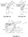
- the joints 50 may be joints of one of several different kinds including, but not limited to, a compliant wire ( FIG. 11a ), a traditional ball-and-socket joint assembly ( FIG. 11b ), a coiled extension spring ( FIG. 11c ), and others.
- Coiled extension springs provide some additional elasticity in the axial direction, which a traditional ball and socket joint does not. This added axial elasticity may extend the allowable range of motion of the VC mechanism 16.
- the plate 26 and attached handle 24 pull away from the user's hand due to the kinematics of the tripod mechanism.
- coiled springs When coiled springs are used, they can stretch axially and allow the user to move the handle 24 freely, providing a greater deflection.
- Coiled springs may make the tool 10 according to the present invention more robust, minimizing the need for maintenance and chances of failure.
- other possible mechanisms to create a virtual center at the wrist may include any other linkage mechanism with any number of rigid or compliant links wherein the trajectory of one (floating) link is generally restricted to motion on the surface of a sphere (2 DoF rotation) centered at the wrist.
- the VC mechanism 16 may include a floating plate 26 that the user's hand can actuate, such as via a handle 24, with respect to the frame 18.
- the VC mechanism 16 ensures that this plate 26, and therefore the handle 24, is restricted to move as if virtually pivoted around a point at the user's wrist via a 2 DoF or 3DoF joint.
- the VC mechanism 16 should provide a virtual center located at the user's wrist as best as possible. Second, the virtual center created by the VC mechanism 16 should remain located close to the user's wrist throughout the mechanism's entire range of motion. However, the VC mechanism 16 may cause a drift in the location of the virtual center, typically with large rotational displacements by the user.
- the location of the virtual center can drift along the axis of the tool 10, which is a consequence of the mechanism type and geometry. Dimensions and geometry can be chosen to minimize the magnitude of this drift, but a small amount may remain. In that case, it is desirable that the VC mechanism 16 provide some means for accommodating the deviation of the virtual center from the user's actual wrist rotation point (such as the springs described above). If this is not provided, the range by which the user can move the plate 26, via the handle 24, smoothly and effortlessly in the yaw and pitch rotational directions may become restricted.
- the VC mechanism 16 should allow for a practical transmission method to transmit the floating plate 26 pitch and yaw motions, actuated by the user's hand via the handle 24, to the end effector 12.
- a cascaded VC mechanism 16 may be provided which resolves the user input (which can be a general combination of pitch and yaw) and into two clearly separated single rotations.
- a first intermediate member or plate 54 when the floating plate 26 is rotated by yaw and pitch, a first intermediate member or plate 54 only experiences the yaw part of the overall input motion while rejecting the pitch component, whereas a second intermediate member or plate 56 only experiences the pitch part of the overall motion while rejecting the yaw component.
- Cables (not shown) mechanically coupled to the first and second intermediate members 54, 56 then transmit the separate pitch and yaw motions to the end effector 12.
- Cam surfaces similar to those described above with reference to FIG. 7 , may be provided on one or both of the first and second intermediate members 54, 56 in order to prevent cable slack. This configuration reduces the one 2-DoF transmission design problem, which has to transmit two rotations at the same time, into two 1-DoF transmission design problems, each of which have to transmit only one rotation independent of the other.
- the floating plate 26 of the VC mechanism 16 may be connected to the intermediate member 54 via a first set of connectors 58.
- Connectors 58 may be such that they transmit a yaw rotation from the floating plate 26 to the first intermediate member 54 because the connectors 58 are stiff in that direction.
- the first intermediate member 54 may be connected to the frame 18 via a second set of connectors 60. Because the connectors 58 are compliant in the pitch direction and the connectors 60 are stiff with respect to pitch rotation relative to the frame 18, any pitch rotation of the floating plate 26 does not get transmitted to the first intermediate member 54.
- this VC mechanism 16 provides a mechanical filtering arrangement such that, given any random combination of yaw and pitch rotations of the plate 26 (actuated by the user's hand such as via the handle 24), only the yaw component of that rotation is seen by the first intermediate member 54, while the pitch component of the overall rotation is rejected or not seen by the first intermediate member 54.
- the plate 26 is attached to the second intermediate member 56 via a third set of connectors 62 which are stiff in the pitch direction and compliant in the yaw direction.
- the second intermediate member 56 is attached to the frame 18 via a fourth set of connectors 64 which are stiff in the yaw direction and compliant in the pitch direction.
- any pitch rotation of the floating plate 26 is transmitted to the second intermediate member 56 via the connectors 62.
- any yaw rotation of the plate 26 is not transmitted to the second intermediate member 56 since the connectors 62 are compliant in this direction and the connectors 64 are stiff in this direction.
- this embodiment of the VC mechanism 16 is able to separate out the combined yaw and pitch rotations of the floating plate 26 into a pure yaw rotation of the first intermediate member 54 and a pure pitch rotation of the second intermediate member 56.
- intermediate members 54, 56 may be used to further transmit the yaw and pitch rotations to the end effector 12 via coupling to cables (not shown).
- two relatively independent 1-DoF transmission problems may be dealt with as opposed to a single 2-DoF transmission problem.
- the members 54, 56 and connectors 58, 60, 62, and 64 are not limited to the shapes and configurations depicted herein.
- Connectors 60 and 64 may be oriented such that an extrapolation of their lengths would intersect at the user's wrist. This may provide the virtual center attribute of the VC mechanism 16. Connectors 58 and 62 may be shaped such that they do not impose any constraint along the tool axis 52. Thus, any deviation of the virtual center provided by connectors 60 and 64 from the actual wrist center of the user may be accommodated by the axial direction compliance of connectors 58 and 62.
- This VC mechanism 16 provides a method to transmit the pitch and yaw rotations about the respective fixed axes, actuated by the user's hand via the handle 24, to the end effector 12. This may be accomplished by resolving the user input (which can be a general combination of pitch and yaw) into two clearly separated single rotations about their fixed respective axes.
- the VC mechanism 16 includes two fixed orthogonal pivots whose extended lines of rotation intersect, and thus create a virtual center, at the location of the user's wrist.
- This VC mechanism 16 ensures that the handle 24, and therefore the user's hand, is allowed to move as if virtually pivoted about a point located at the user's wrist. It should be noted that the handle 24 in this embodiment can move in towards or out away from the arm attachment location, allowing the tool 10 to naturally adapt to a wide range of user hand and arm sizes, and ensuring that there is no restriction to the natural range of motion of the user's wrist.
- the handle 24 and the floating plate 26 may be connected to a first, pitch connector 66 and a second, yaw connector 68 as shown.
- Each connector 66, 68 may in turn be pinned about a shaft 70, 72 on the respective pitch 74 and yaw 76 axes, wherein the pitch shaft 70 may receive a pitch axis pulley 78 and the yaw shaft 72 may receive a yaw axis pulley 80.
- the shafts 70, 72 are connected to the frame 18, which is secured to the user's arm, such that the rotations are relative to the VC mechanism 16 itself.
- the pitch connector 66 is stiff about the pitch axis, but is compliant about the yaw axis, allowing for the transmission of only the pitch component of the rotation while filtering the yaw component by allowing unconstrained rotation of the pitch connector 66 about the yaw axis.
- the opposite is true for the yaw connector 68, which will strictly transmit any yaw component of rotation while it will reject any pitch component of rotation.
- This design reduces the one 2-DoF transmission design problem, which has to transmit two rotations at the same time, into two 1-DoF transmission design problems, each of which have to transmit only one rotation independent of the other, such that the motion and force inputs about fixed axes may be easily transmitted to the end effector 12.
- the resulting virtual center location remains static with respect to the tool frame 18 (and therefore the user's forearm) at all times.
- this fixed axes VC mechanism 16 provides a mechanical filtering arrangement such that, given any general combination of yaw and pitch rotations to the handle 24 via the user's hand, only the yaw component of that rotation is seen by the yaw connector 68 while the pitch component of the overall rotation is rejected and not experienced about the yaw axis 76, and only the pitch component is seen by the pitch connector 66 while the yaw component is rejected and not experienced about the pitch axis 74.
- the combined yaw and pitch rotations of the handle 24 may be separated into a pure yaw rotation about the yaw axis 76 and a pure pitch rotation about the pitch axis 74.
- the rotations about the respective pitch and yaw axes 74, 76 may be used to transmit the desired yaw and pitch rotations to the pitch and yaw axes of the end effector 12.
- the rotations produced at the pitch and yaw axis pulleys 78, 80 may be individually transmitted to the end effector 12 using a cable arrangement (not shown) similar to the one described above.
- the orthogonal pitch and yaw axes of rotation intersect at the location of the wrist, providing the desired VC mechanism 16 behavior.
- the location of the virtual center will remain stationary throughout the range of motion of the VC mechanism 16.
- the geometry of the connectors 66, 68 is such that they do not impose any constraint along the tool axis 52 (see FIG. 9 ), allowing for handle 24 adjustability by the user.
- the fixed axes of rotation provide a trivial transmission method that can independently transmit pitch and yaw components of a rotational input by the user to the end effector 12 while maintaining a constant transmission cable length.
- the present invention provides a 2 DoF (pitch and yaw) output joint 32 for motion output at the end effector 12.
- the output joint 32 transmits roll rotation from the tool shaft 22 to the end effector 12. Since the tool shaft 22 is part of the continuous rigid structure, and since the continuous rigid structure is secured to the user's forearm, the roll rotation of the user's forearm can be transmitted to the end effector 12. Therefore, a 2-DoF rotational joint, that provides pitch and yaw rotation DoF, mounted to the in vivo portion of the tool shaft 22 may be used for this purpose.
- the output joint 32 may be provided with a third DoF (roll rotation), along with an appropriate method for actuating this roll rotation by the user at the tool's input end 14.
- the output joint 32 may be a flexible, snake-like joint, such as one comprising flexible disks 82 attached in a fashion such that the direction of flexure of each element alternates.
- This joint 32 can be actuated by pushing or pulling on the disks 82 in different places, causing expansion and contraction of its sides. Cables (not shown) running through each disk 82 of the output joint 32 may be selectively pulled to create deflection in the yaw and pitch rotation directions or any combination thereof.
- the output joint 32 may also be realized by means of a VC mechanism as illustrated in FIG. 14b , similar in intent to the one used at the input joint 16 described above. Barring space constraints, such a VC mechanism at the output joint 32 provides a center-of-rotation for the end effector 12 that can be conveniently located at any location other than the physical location of the output joint 32.
- the present disclosure also provides a method to relate a user's grasp (from thumb/fingers) to the end effector 12.
- a grasping motion of the end effector 12 may be actuated via a cable system that passes from the handle 24 to the end effector 12.
- the input motion device may comprise a lever 84 mounted on the handle 24 that is mechanically coupled to the end effector 12 for actuating a grasping motion of the end effector 12.
- a cable 86 may be attached to the lever 84 and an associated closure mechanism 88 provided, wherein the cable 86 may transmit the grasping motion from the lever 84 and the closure mechanism 88 to the end effector 12.
- the grasping transmission system transmits one grasping DoF from the user's thumb/fingers to a corresponding open/close action (also one DoF) at the end effector 12. Since the handle 24 will move along with the user's hand, thumb and fingers during wrist motion, providing the lever 84 and the closure mechanism 88 on the handle 24 ensures that the input device for providing the grasping motion does not move relative to the hand, thumb, and fingers.
- a flexure element 90 such as a piece of spring steel, may be used as a one-DoF joint, wherein this joint may be compliant in nature so as to automatically return to its nominal (undeformed) position. This automatic return is desirable to ease the motion input requirements for the user's thumb.
- any one-DoF joint could be used for this actuation, for example, a pin, slider, or push button (compliant or spring-mounted), provided one end is mounted to the handle 24 and the other is acted on by the fingers or thumb.
- thumb actuation allows the user to grasp the handle 24 with their fingers and palm while independently actuating the lever 84.
- a finger-actuated lever could alternatively be used, depending on size constraints from the shape of the handle 24.
- the closure mechanism 88 may include a ratcheting mechanism which allows the user to lock the lever 84 in different positions.
- This device may also use a compliant one DoF flexure joint 92 as shown in FIG. 15 .
- the ratcheting mechanism is similar to those seen in U.S. Patent Nos. 5,209,747 and 4,950,273 and may comprise a toothed body 94 that engages a single tooth on the lever 84 in different positions. As the user depresses the lever 84, the toothed body 94 deflects about axis (b) and allows the lever 84 to slip down to the next tooth. When the user releases the lever 84, it remains at whatever current position it is in.
- the toothed body 94 is simply deflected forward by the user's thumb causing the ratchet teeth to disengage.
- the springiness of the flexure joint 92 holding the lever 84 causes the lever 84 to go back to its nominal condition.
- any other variable closure mechanism may be used instead of the ratcheting mechanism, depending on the specifics of the application.
- Such a mechanism provides the user the ability to hold a grasp (for example, on a tissue) inside the patient's body via the jaws 96 of the end effector 12.
- the handle 24 moves along with the user's hand and wrist, such that the distance between the user input and the tool output is variable. Because each user input motion should be independent for the desired tool functionality, a transmission means that allows for a variable distance and orientation between components is generally desirable.
- relative motion between the cable 86 and a sheath may be used for actuation.
- the 86 cable may attach to the end effector 12, pass through the tool shaft 22, pass through the sheath to the floating plate 26 of the VC mechanism 16, pass through the handle 24, and then attach to the lever 84.
- the sheath may be connected between the tool frame 18 and the plate 26.
- the sheath through which the transmission cable 86 runs between the tool frame 18 and floating plate 26 can be any type of hollow body that is flexible in bending.
- the sheath may include a flexible coiled spring or nylon tubing that provides enough flexibility in bending, but has a high stiffness under compression. This stiffness ensures that the relative motion between the cable 86 and the sheath dominate during tension in the transmission cable 86.
- the cable 86 acts the same regardless of the shape of the sheath. With slack introduced in the sheath, the cable 86 can be straightened for a certain distance and without the grasping actuation force in the cable 86 being affected.
- This cable/sheath system may be implemented in various ways, but ultimately should allow for a variable distance between the tool frame 18 and the floating plate 26 of the VC mechanism 16. It should be noted that such a cable/sheath arrangement may be used not only for the grasping action transmission, but also for the transmission of the wrist rotations from the input joint 16 to the output joint 32. For example, separate sheaths could be employed for two pitch transmission cables, two yaw cables, and one grasping actuation cable.
- the end effector 12 reproduces the user's actions in vivo.
- the end effector 12 can be any number of one DoF devices, such as scissors, shears, needle drivers, dissectors, graspers, or retractors. These end effectors 12 may be compliant or rigid, and may have active and passive components (depending on the motion transmission system).
- the embodiment shown includes a compliant grasping mechanism that is at equilibrium in the open (or grasp-release) position. When the center of this grasper is pulled axially backwards, the jaws 96 of the end effector 12 close inward. In addition to grasping, the jaws 96 may have other functionality such as, but not limited to, cutting or cauterizing of tissue.
- transmission between the input joint 16 and the output joint 32 may be accomplished via a pulley and cable system for each of the two wrist DoF as described with respect to several embodiments above.
- the design may incorporate a mechanism to scale the user's input rotation ( ⁇ ) reflected at an input pulley 98 to the tool output rotation ( ⁇ ) at an output pulley 100 by some transmission ratio T, thereby providing a variable transmission ratio between the tool input (user's hand rotation about his/her wrist) and tool output (end-effector 12 rotation about the output joint 32).
- This transmission ratio T may be fixed, may be changed in discrete steps, or may be changed continuously. Any fixed transmission ratio may be achieved by choosing appropriate radii for the input and output pulleys 98, 100.
- a discretely variable transmission ratio may be accomplished by means of a stepped configuration of the input and output pulleys 98, 100 such as that shown in FIG. 17 , and a shifting mechanism (not shown) that allows a user to change between ratios.
- a continuously variable transmission CVT
- Such a CVT may be implemented by an intermediate module 102 such as, but not limited to, a V-Belt or toroidal arrangement, wherein a generic CVT arrangement is shown in FIG. 18 .
- the CVT embodiment is illustrated in an arrangement that utilizes input and output pulleys 98, 100, it is understood that pulleys 98, 100 are not required for the implementation of a CVT in accordance with the present invention.
- the tool 10 may incorporate an end-effector 12 and output joint 32 that decouple the actuation of the pitch and yaw DoF at the tool out put.
- the tool output comprises an end effector 12 and a 2-DoF rotational joint 32 about which the end-effector 12 can rotate.
- the actuation of three motions two wrist-like rotations of the end-effector 12 about the output joint 32, and one open/close motion of the end effector jaws 96) are decoupled in this embodiment.
- Pin-based joints can achieve large rotations in very small spaces, but their mechanical implementation can result in the coupling of rotations in cascaded arrangements.
- the pitch rotation of the tool is implemented after the yaw rotation and, as a result, the transmission cable actuation to produce a desired pitch depends on the current yaw angle. This is referred to as end effector motion coupling and results in non-intuitive tool output behavior.
- the output joint 32 includes a pair of nested rings 104, 106.
- the outer ring 104 may be connected by a pin joint to the tool shaft 22, and is actuated by a pair of cables (not shown) which may be attached to the outer ring 104 generally at the location of the pitch axis and which produce a rotation about the yaw axis.
- the inner ring 106 is pinned to the outer ring 104 so that the pitch axis is orthogonal to the yaw axis.
- the inner ring 106 is also driven by a pair of drive cables (not shown) which may be attached to the inner ring 106 at generally the same height as the outer ring 104 and generally at the location of the yaw axis.
- the two joints create a center of rotation acting at the intersection of the pitch and yaw axes.
- This arrangement prevents motion coupling by co-locating the two joint axes in an arrangement that would not be feasible with traditional cascaded, pin-based joints.
- This end effector 12 and output joint 32 design allows the tool 10 according to the present invention to be operated with a smaller radius of curvature, thus providing a tighter workspace which is desirable for the surgeon (user).
- This output joint 32 also fully separates the pitch and yaw motions to allow for completely independent motions, thus keeping the rotations mechanically decoupled.
- the tool shaft 22 may be easily replaceable while the frame 18 remains attached to the user's arm. This feature allows the user to quickly replace the tool shaft 22 and end effector 12 without having to remove the entire tool 10 from his or her arm.
- a cable junction 108 may be provided at the connection point between the tool shaft 22 and the frame 18.
- a junction 108 may be introduced at the base of the tool frame 18, such that one part of the frame 18 that supports to the tool input remains attached to the user's forearm via the arm attachment member 20, while the rest of the frame 18 along with the tool shaft 22 is replaceable.
- transmission cable connections must be severed and reconnected while maintaining sufficient cable tension to allow effective input-output motion transmission.
- These links could be established by a quick release mechanism 110 such as, but not limited to, a snap-fitting mechanism, magnetic coupling, or some other method of temporarily joining and releasing two tensile members. This link can be severed and reattached as desired during a surgery to allow the user to switch tool shafts 22 without having to change or remove the arm attachment member 20.
- the tool 10 according to the present invention may result in significantly reduced forces at the surgical port, which in turn reduces skin/tissue trauma for the patient.
- placement of the tool input joint between the handle and the tool shaft makes the actuation of the tool dependent on the presence of an external ground reference, which can provide reaction loads, or in other words, close the load loop.
- the user applies a torque at the tool handle, and the surgical port acts as the external ground reference to provide the balancing loads necessary to allow the handle to tip downwards, which then tips the end-effector downwards.
- the load loop in this case, comprises the tool handle, tool shaft, surgical port, patient's body, the ground that the patient's body rests on, the ground that the surgeon (user) stands on, the surgeon's body, the surgeon's forearm, and the surgeon's hand that grips the tool handle - in that order.
- all the tool actuation loads necessarily flow through the surgical port and patient's body. These loads are particularly detrimental to the skin and tissue surrounding the surgical port, in the case of young or elderly patients.
- the tool 10 provides a common ground frame 18 that bridges the tool shaft 22 and the user's forearm.
- Employing the user's forearm as a ground reference locally closes the load loop associated with the wrist DoF actuation forces.
- the load loop comprises the handle 24, the VC mechanism 16, the frame 18, the arm attachment member 20, and the user's arm and hand. Contrary to existing hand-held tools, this entirely eliminates the need for an external ground reference, such as the surgical port, to provide reaction loads.
- the frame 18 may be mounted on a bed frame or other structure 112 external to the user's body via an interface mechanism 114 connected therebetween which may help support the weight of the tool 10.
- This interface mechanism 114 may generally provide 6 DoF between the external structure 112 and the frame 18 to avoid over-constraining or limiting the motion of the tool 10. The surgeon (user) can then place his/her arm into the arm attachment member 20 and guide the tool 10 as described above while the external structure 112 supports the weight of the tool 10.
- an end effector 12 using an input joint that may include a VC mechanism 16 is described above, in another application, a similar VC mechanism-based input joint may be used to actuate the motion of an endoscopic device. Such an arrangement would provide the user with an intuitive and ergonomic means for guiding the endoscopic device inside a patient's body.
Claims (13)
- Outil d'accès minimal (10) comprenant:un cadre (18);un arbre d'outil (22) ayant une extrémité proximale et une extrémité distale, l'extrémité proximale de l'arbre d'outil étant reliée au cadre;une articulation d'entrée (16) ayant une première extrémité connectée au cadre et une seconde extrémité agencée pour recevoir une entrée d'utilisateur; etune articulation de sortie (32) reliée à l'extrémité distale (23) de l'arbre d'outil, dans lequel l'articulation de sortie est couplée à l'articulation d'entrée par le biais d'une transmission mécanique connectée entre eux pour corréler le mouvement de l'articulation d'entrée au mouvement de l'articulation de sortie,dans lequel l'articulation d'entrée comprend un mécanisme de centre de rotation virtuel (VC) qui fournit un centre de rotation qui coïncide généralement avec une articulation de poignet (W) de l'utilisateur, le mécanisme VC fournissant les mêmes deux degrés de liberté, à savoir rotation en tangage et rotation en lacet, comme l'articulation du poignet de l'utilisateur, etdans lequel la transmission mécanique est agencée pour transmettre les deux rotations du mécanisme VC, transmettant ainsi la rotation en tangage et la rotation en lacet de l'articulation de poignet de l'utilisateur à deux rotations correspondantes de l'articulation de sortie,caractérisé en ce quele cadre (18) est agencé se fixer à l'avant-bras de l'utilisateur par le biais d'un élément de fixation de bras (20).
- Outil selon la revendication 1, dans lequel la transmission mécanique comprend des câbles (34).
- Outil selon la revendication 2, dans lequel les câbles (34) sont acheminés à travers l'arbre d'outil (22).
- Outil selon la revendication 1, dans lequel la transmission mécanique comprend un rapport de transmission variable.
- Outil selon la revendication 1, dans lequel la seconde extrémité de l'articulation d'entrée comprend un élément flotteur (26) pour recevoir une entrée de l'utilisateur, et notamment une poignée (24) montée sur l'élément flottant (26) ou incorporée à celui-ci comme composant unique, qui peut alors être saisie par la main de l'utilisateur.
- Outil selon la revendication 1, comprenant en outre un effecteur d'extrémité (12) connecté à l'articulation de sortie (32).
- Outil selon la revendication 6, dans lequel l'effecteur d'extrémité (12) est détachable de l'articulation de sortie (32).
- Outil selon la revendication 6, dans lequel l'effecteur d'extrémité (12) comprend des mâchoires (96) capables de mouvements d'ouverture et de fermeture.
- Outil selon la revendication 1, comprenant en outre un mécanisme à déverrouillage rapide (110) pour dégager l'arbre de l'outil (22) du cadre (18).
- Outil selon la revendication 1 dans lequel:le mécanisme de centre de rotation virtuel (VC) est configuré de sorte que le centre de rotation reste stationnaire dans toute la plage de mouvement du mécanisme VC, le mécanisme VC comprenant un connecteur en tangage (66) et un connecteur en lacet (68) connectés entre la première extrémité et la seconde extrémité d'articulation d'entrée, dans lesquelles le connecteur en tangage est conforme uniquement à un axe de lacet par rapport au cadre (18) et le connecteur en lacet est conforme uniquement à un axe de tangage par rapport au cadre, découplant ainsi deux degrés de mouvement de rotation de liberté du mécanisme VC dans des rotations distinctes à un degré de liberté présenté sur une poulie d'axe de tangage (78) et une poulie d'axe de lacet (80); etla transmission comprend des câbles (34) pour coupler mécaniquement l'articulation de sortie (32) à l'articulation d'entrée (16).
- Outil selon la revendication 10, comprenant en outre:un arbre d'axe de tangage (70) pour coupler le connecteur de tangage (66) au cadre (18); un arbre d'axe de lacet (72) pour coupler le connecteur de lacet (68) au cadre (18); dans lequel la poulie d'axe de tangage (78) est reçue sur l'arbre d'axe de tangage; etdans lequel la poulie d'axe de lacet (80) est reçue sur l'arbre d'axe de lacet,dans lequel les câbles (34) sont connectés aux poulies d'axe de tangage et d'axe de lacet pour transmettre des rotations de tangage et de lacet découplées, respectivement, à l'articulation de sortie (32).
- Outil selon la revendication 10 ou la revendication 11, dans lequel une poignée (24), et donc la main de l'utilisateur, peut se rapprocher ou s'éloigner de l'élément de fixation du bras (20) permettant à l'outil (10) de s'adapter naturellement à une plage de tailles de main et de bras de l'utilisateur, de sorte qu'il n'y a pas de restriction à l'amplitude naturelle du mouvement du poignet de l'utilisateur.
- Outil selon l'une quelconque des revendications 10 à 12, dans lequel l'emplacement du centre virtuel reste statique par rapport à l'avant-bras de l'utilisateur.
Applications Claiming Priority (2)
| Application Number | Priority Date | Filing Date | Title |
|---|---|---|---|
| US4416808P | 2008-04-11 | 2008-04-11 | |
| PCT/US2009/040353 WO2009126955A2 (fr) | 2008-04-11 | 2009-04-13 | Outil d’accès minimal |
Publications (3)
| Publication Number | Publication Date |
|---|---|
| EP2268211A2 EP2268211A2 (fr) | 2011-01-05 |
| EP2268211A4 EP2268211A4 (fr) | 2012-10-10 |
| EP2268211B1 true EP2268211B1 (fr) | 2018-02-14 |
Family
ID=41162680
Family Applications (1)
| Application Number | Title | Priority Date | Filing Date |
|---|---|---|---|
| EP09729763.4A Active EP2268211B1 (fr) | 2008-04-11 | 2009-04-13 | Outil d'accès minimal |
Country Status (6)
| Country | Link |
|---|---|
| US (2) | US8668702B2 (fr) |
| EP (1) | EP2268211B1 (fr) |
| JP (1) | JP5513483B2 (fr) |
| AU (1) | AU2009234288B2 (fr) |
| CA (1) | CA2721216C (fr) |
| WO (1) | WO2009126955A2 (fr) |
Families Citing this family (60)
| Publication number | Priority date | Publication date | Assignee | Title |
|---|---|---|---|---|
| US10405936B2 (en) * | 2008-04-11 | 2019-09-10 | The Regents Of The University Of Michigan | Parallel kinematic mechanisms with decoupled rotational motions |
| US9869339B2 (en) | 2008-04-11 | 2018-01-16 | Flexdex, Inc. | End-effector jaw closure transmission systems for remote access tools |
| US9629689B2 (en) | 2008-04-11 | 2017-04-25 | Flexdex, Inc. | Attachment apparatus for remote access tools |
| WO2009126955A2 (fr) | 2008-04-11 | 2009-10-15 | The Regents Of The University Of Michigan | Outil d’accès minimal |
| US8968355B2 (en) * | 2008-08-04 | 2015-03-03 | Covidien Lp | Articulating surgical device |
| US8262894B2 (en) | 2009-04-30 | 2012-09-11 | Moses Lake Industries, Inc. | High speed copper plating bath |
| CN113967039A (zh) | 2009-11-13 | 2022-01-25 | 直观外科手术操作公司 | 具有紧凑腕部的手术工具 |
| US20110118708A1 (en) | 2009-11-13 | 2011-05-19 | Intuitive Surgical Operations, Inc. | Double universal joint |
| EP2498710B1 (fr) | 2009-11-13 | 2018-05-16 | Intuitive Surgical Operations, Inc. | Interface de moteur pour arbres d'entraînement parallèles dans un élément tournant indépendamment |
| WO2011060311A2 (fr) | 2009-11-13 | 2011-05-19 | Intuitive Surgical Operations, Inc. | Effecteur terminal pourvu de mécanismes de fermeture redondants |
| CA2786480C (fr) | 2010-01-26 | 2018-01-16 | Novolap Medical Ltd. | Instrument medical articule |
| WO2012049623A1 (fr) | 2010-10-11 | 2012-04-19 | Ecole Polytechnique Federale De Lausanne (Epfl) | Manipulateur mécanique destiné à des instruments chirurgicaux |
| US8828046B2 (en) * | 2010-10-14 | 2014-09-09 | Ethicon Endo-Surgery, Inc. | Laparoscopic device with distal handle |
| WO2012074564A1 (fr) | 2010-12-02 | 2012-06-07 | Freehand Endoscopic Devices, Inc. | Instrument chirurgical |
| US9186220B2 (en) | 2010-12-17 | 2015-11-17 | Ethicon Endo-Surgery, Inc. | Surgical system and methods for mimicked motion |
| WO2013014621A2 (fr) | 2011-07-27 | 2013-01-31 | Ecole Polytechnique Federale De Lausanne (Epfl) | Dispositif mécanique télécommandé pour manipulation à distance |
| WO2013035870A1 (fr) * | 2011-09-08 | 2013-03-14 | オリンパスメディカルシステムズ株式会社 | Pinces à degrés de liberté multiples |
| US9241770B2 (en) | 2011-09-30 | 2016-01-26 | Ethicon Endo-Surgery, Inc. | Methods and devices for remotely controlling movement of surgical tools |
| US9179927B2 (en) | 2011-12-02 | 2015-11-10 | Ethicon Endo-Surgery, Inc. | Surgical methods using a surgical device having a fixed angular orientation |
| US8617203B2 (en) | 2011-12-02 | 2013-12-31 | Ethicon Endo-Surgery, Inc. | Jaw assembly for surgical devices |
| US9131987B2 (en) | 2011-12-02 | 2015-09-15 | Ethicon Endo-Surgery, Inc. | Elbow assembly for surgical devices |
| US9211159B2 (en) | 2011-12-02 | 2015-12-15 | Ethicon Endo-Surgery, Inc. | Surgical devices with intracorporeal elbow joint |
| US9044258B2 (en) * | 2011-12-27 | 2015-06-02 | Specialty Surgical Instrumentation Inc. | Instrument with removable tip |
| WO2014033717A1 (fr) | 2012-08-30 | 2014-03-06 | Human Extensions Ltd. | Interface entre un utilisateur et des instruments laparoscopiques |
| DK3038542T3 (en) | 2013-09-01 | 2019-04-15 | Human Extensions Ltd | CONTROL UNIT FOR A MEDICAL DEVICE |
| CN106659540B (zh) | 2014-02-03 | 2019-03-05 | 迪斯塔莫申股份公司 | 包括能互换远端器械的机械遥控操作装置 |
| CN108836480B (zh) * | 2014-04-22 | 2022-05-13 | 香港生物医学工程有限公司 | 外科设备 |
| EP3185808B1 (fr) | 2014-08-27 | 2022-02-23 | DistalMotion SA | Système chirurgical pour techniques de microchirurgie |
| JP6910658B2 (ja) * | 2014-10-02 | 2021-07-28 | リブスメド インコーポレーテッド | 手術用インストルメント |
| US10864052B2 (en) | 2014-12-19 | 2020-12-15 | Distalmotion Sa | Surgical instrument with articulated end-effector |
| EP3232977B1 (fr) | 2014-12-19 | 2020-01-29 | DistalMotion SA | Système d'accueil pour télémanipulateur mécanique |
| EP4342412A2 (fr) | 2014-12-19 | 2024-03-27 | DistalMotion SA | Instrument chirurgical réutilisable pour interventions mini-invasives |
| EP3232973B1 (fr) | 2014-12-19 | 2020-04-01 | DistalMotion SA | Interface stérile pour instruments chirurgicaux articulés |
| EP3232974B1 (fr) | 2014-12-19 | 2018-10-24 | DistalMotion SA | Poignée articulée pour télémanipulateur mécanique |
| KR102153407B1 (ko) * | 2015-02-17 | 2020-09-08 | 주식회사 리브스메드 | 수술용 인스트루먼트 |
| US11344381B2 (en) * | 2015-02-17 | 2022-05-31 | Livsmed Inc. | Instrument for surgery |
| WO2016161449A1 (fr) * | 2015-04-03 | 2016-10-06 | The Regents Of The University Of Michigan | Appareil de gestion de la tension pour transmission entraînée par câble |
| EP3280337B1 (fr) * | 2015-04-09 | 2019-11-13 | DistalMotion SA | Instrument manuel articulé |
| WO2016162752A1 (fr) | 2015-04-09 | 2016-10-13 | Distalmotion Sa | Dispositif mécanique télécommandé pour manipulation à distance |
| KR102473629B1 (ko) | 2015-04-15 | 2022-12-01 | 플렉스덱스 인코포레이티드 | 원격 접근 공구용 부착 장치 |
| EP3851062A1 (fr) | 2015-05-11 | 2021-07-21 | Covidien LP | Unité de commande d'instrument de couplage et instrument chirurgical robotique |
| WO2016187056A1 (fr) * | 2015-05-15 | 2016-11-24 | The Johns Hopkins University | Dispositif manipulateur, méthodes thérapeutiques et diagnostiques |
| JP6771494B2 (ja) | 2015-06-19 | 2020-10-21 | コヴィディエン リミテッド パートナーシップ | 双方向連結部を備えたロボット外科用機器の制御法 |
| WO2017037532A1 (fr) | 2015-08-28 | 2017-03-09 | Distalmotion Sa | Instrument chirurgical doté d'une force d'actionnement accrue |
| CN108712886B (zh) * | 2015-10-02 | 2021-06-04 | 弗莱克斯德克斯公司 | 提供无限制滚转的手柄机构 |
| BR112018006826A2 (pt) | 2015-10-05 | 2018-10-16 | Flexdex Inc | dispositivos médicos que têm juntas multi-cluster que se articulam suavemente |
| US11896255B2 (en) | 2015-10-05 | 2024-02-13 | Flexdex, Inc. | End-effector jaw closure transmission systems for remote access tools |
| US10492819B2 (en) | 2016-04-01 | 2019-12-03 | Ethicon Llc | Surgical instrument with dual mode articulation drive |
| US9993920B2 (en) * | 2016-04-14 | 2018-06-12 | John Hatten | Guitar pick retriever |
| US10813710B2 (en) | 2017-03-02 | 2020-10-27 | KindHeart, Inc. | Telerobotic surgery system using minimally invasive surgical tool with variable force scaling and feedback and relayed communications between remote surgeon and surgery station |
| US11058503B2 (en) | 2017-05-11 | 2021-07-13 | Distalmotion Sa | Translational instrument interface for surgical robot and surgical robot systems comprising the same |
| AU2019218707A1 (en) | 2018-02-07 | 2020-08-13 | Distalmotion Sa | Surgical robot systems comprising robotic telemanipulators and integrated laparoscopy |
| US10441449B1 (en) | 2018-05-30 | 2019-10-15 | Vesper Medical, Inc. | Rotary handle stent delivery system and method |
| US10449073B1 (en) | 2018-09-18 | 2019-10-22 | Vesper Medical, Inc. | Rotary handle stent delivery system and method |
| US11219541B2 (en) | 2020-05-21 | 2022-01-11 | Vesper Medical, Inc. | Wheel lock for thumbwheel actuated device |
| CN115701943A (zh) | 2020-06-02 | 2023-02-14 | 弗莱克斯德克斯公司 | 手术工具和组件 |
| GB2597084A (en) * | 2020-07-14 | 2022-01-19 | Cmr Surgical Ltd | Geared instruments |
| US11737748B2 (en) * | 2020-07-28 | 2023-08-29 | Cilag Gmbh International | Surgical instruments with double spherical articulation joints with pivotable links |
| CN116035725B (zh) * | 2023-01-12 | 2023-06-27 | 美科特医疗科技(苏州)有限公司 | 自适应穿戴环及微创医疗器械 |
| US11844585B1 (en) | 2023-02-10 | 2023-12-19 | Distalmotion Sa | Surgical robotics systems and devices having a sterile restart, and methods thereof |
Citations (1)
| Publication number | Priority date | Publication date | Assignee | Title |
|---|---|---|---|---|
| US5908436A (en) * | 1996-12-18 | 1999-06-01 | Karl Storz Gmbh & Co. | VuMedical handling device in particular for endoscopic applications |
Family Cites Families (87)
| Publication number | Priority date | Publication date | Assignee | Title |
|---|---|---|---|---|
| FR1334446A (fr) | 1961-06-28 | 1963-08-09 | Bolkow Entwicklungen Kg | Articulation sans frottement |
| US3497083A (en) | 1968-05-10 | 1970-02-24 | Us Navy | Tensor arm manipulator |
| US4328839A (en) | 1980-09-19 | 1982-05-11 | Drilling Development, Inc. | Flexible drill pipe |
| JPS5920946Y2 (ja) * | 1981-05-30 | 1984-06-18 | 株式会社トミー | ロボツトハンド玩具 |
| JPS58132490A (ja) | 1982-01-29 | 1983-08-06 | 株式会社日立製作所 | 角度伝達機構 |
| US4712545A (en) | 1984-04-05 | 1987-12-15 | Acufex Microsurgical, Inc. | Surgical instrument |
| US4754909A (en) | 1984-08-09 | 1988-07-05 | Barker John M | Flexible stapler |
| JPS6233801U (fr) | 1985-08-14 | 1987-02-27 | ||
| US4950273A (en) | 1987-10-26 | 1990-08-21 | Briggs Jeffrey M | Cable action instrument |
| US5021969A (en) | 1988-03-17 | 1991-06-04 | Kabushiki Kaisha Toshiba | Manipulator operating apparatus |
| JPH0646935B2 (ja) * | 1990-04-09 | 1994-06-22 | 工業技術院長 | マスタスレイブ・マイクロ機構 |
| US5069596A (en) | 1990-07-10 | 1991-12-03 | Lawter International, Inc. | Bulk bag handling and discharging apparatus |
| US5209747A (en) | 1990-12-13 | 1993-05-11 | Knoepfler Dennis J | Adjustable angle medical forceps |
| US5147357A (en) | 1991-03-18 | 1992-09-15 | Rose Anthony T | Medical instrument |
| US5317952A (en) | 1991-11-22 | 1994-06-07 | Kinetic Sciences Inc. | Tentacle-like manipulators with adjustable tension lines |
| US6788999B2 (en) | 1992-01-21 | 2004-09-07 | Sri International, Inc. | Surgical system |
| US5297443A (en) | 1992-07-07 | 1994-03-29 | Wentz John D | Flexible positioning appendage |
| US5330502A (en) | 1992-10-09 | 1994-07-19 | Ethicon, Inc. | Rotational endoscopic mechanism with jointed drive mechanism |
| US5374277A (en) | 1992-10-09 | 1994-12-20 | Ethicon, Inc. | Surgical instrument |
| US5350391A (en) | 1992-10-19 | 1994-09-27 | Benedetto Iacovelli | Laparoscopic instruments |
| US5323570A (en) | 1993-01-25 | 1994-06-28 | General Motors Corporation | Door opening cable system with cable slack take-up |
| DE69409565T2 (de) | 1993-01-29 | 1998-10-01 | Smith & Nephew Inc | Schwenkbares gekrümmtes Instrument |
| DE4306786C1 (de) * | 1993-03-04 | 1994-02-10 | Wolfgang Daum | Chirurgischer Manipulator |
| JP2665052B2 (ja) | 1993-05-14 | 1997-10-22 | エスアールアイ インターナショナル | 遠隔中心位置決め装置 |
| US5368600A (en) | 1993-07-23 | 1994-11-29 | Ethicon, Inc. | Steerable bulldog clamp applier |
| US5456695A (en) | 1993-10-25 | 1995-10-10 | United States Surgical Corporation | Multi-tool surgical apparatus |
| US5454827A (en) | 1994-05-24 | 1995-10-03 | Aust; Gilbert M. | Surgical instrument |
| US5807376A (en) * | 1994-06-24 | 1998-09-15 | United States Surgical Corporation | Apparatus and method for performing surgical tasks during laparoscopic procedures |
| US5549637A (en) | 1994-11-10 | 1996-08-27 | Crainich; Lawrence | Articulated medical instrument |
| US5713505A (en) | 1996-05-13 | 1998-02-03 | Ethicon Endo-Surgery, Inc. | Articulation transmission mechanism for surgical instruments |
| US5683412A (en) | 1994-12-23 | 1997-11-04 | Symbiosis Corporation | Force-limiting control member for endoscopic instruments and endoscopic instruments incorporating same |
| US5860995A (en) | 1995-09-22 | 1999-01-19 | Misener Medical Co. Inc. | Laparoscopic endoscopic surgical instrument |
| US5820009A (en) | 1996-02-20 | 1998-10-13 | Richard-Allan Medical Industries, Inc. | Articulated surgical instrument with improved jaw closure mechanism |
| DE19608716C1 (de) | 1996-03-06 | 1997-04-17 | Aesculap Ag | Bipolares chirurgisches Faßinstrument |
| US5626608A (en) | 1996-03-29 | 1997-05-06 | United States Surgical Corporation | Surgical instrument having locking handle |
| US5735874A (en) | 1996-06-21 | 1998-04-07 | Ethicon Endo-Surgery, Inc. | Variable position handle locking mechanism |
| US5782748A (en) * | 1996-07-10 | 1998-07-21 | Symbiosis Corporation | Endoscopic surgical instruments having detachable proximal and distal portions |
| US6330837B1 (en) | 1997-08-28 | 2001-12-18 | Microdexterity Systems, Inc. | Parallel mechanism |
| US6714839B2 (en) | 1998-12-08 | 2004-03-30 | Intuitive Surgical, Inc. | Master having redundant degrees of freedom |
| US6309403B1 (en) | 1998-06-01 | 2001-10-30 | Board Of Trustees Operating Michigan State University | Dexterous articulated linkage for surgical applications |
| US6852107B2 (en) | 2002-01-16 | 2005-02-08 | Computer Motion, Inc. | Minimally invasive surgical training using robotics and tele-collaboration |
| JP2000193893A (ja) | 1998-12-28 | 2000-07-14 | Suzuki Motor Corp | 検査用挿入管の屈曲装置 |
| EP1224918A3 (fr) | 1999-05-10 | 2002-12-18 | endoVia Medical Inc. | Instrument chirurgical |
| US6312435B1 (en) | 1999-10-08 | 2001-11-06 | Intuitive Surgical, Inc. | Surgical instrument with extended reach for use in minimally invasive surgery |
| US6902560B1 (en) | 2000-07-27 | 2005-06-07 | Intuitive Surgical, Inc. | Roll-pitch-roll surgical tool |
| JP4014792B2 (ja) * | 2000-09-29 | 2007-11-28 | 株式会社東芝 | マニピュレータ |
| EP1199840A1 (fr) | 2000-10-19 | 2002-04-24 | THOMSON multimedia | Méthode pour connecter, via une liaison sans fil, un appareil éloigné de type IEEE1394 à un groupe d'appareils de type IEEE1394 |
| US6817974B2 (en) * | 2001-06-29 | 2004-11-16 | Intuitive Surgical, Inc. | Surgical tool having positively positionable tendon-actuated multi-disk wrist joint |
| JP3926119B2 (ja) | 2001-08-10 | 2007-06-06 | 株式会社東芝 | 医療用マニピュレータ |
| JP3631450B2 (ja) * | 2001-08-22 | 2005-03-23 | 株式会社東芝 | マニピュレータ |
| US7261728B2 (en) | 2002-03-15 | 2007-08-28 | Ethicon Endo-Surgery, Inc. | Biopsy forceps device and method |
| JP3680050B2 (ja) | 2002-09-18 | 2005-08-10 | 株式会社東芝 | 医療用マニピュレータ及びその制御方法 |
| JP3912251B2 (ja) | 2002-10-02 | 2007-05-09 | 株式会社日立製作所 | マニピュレータ |
| CN100389730C (zh) | 2002-12-06 | 2008-05-28 | 直观外科手术公司 | 用于手术工具的柔性肘节 |
| JP4286571B2 (ja) * | 2003-03-31 | 2009-07-01 | 独立行政法人科学技術振興機構 | 手術装置 |
| US7591783B2 (en) | 2003-04-01 | 2009-09-22 | Boston Scientific Scimed, Inc. | Articulation joint for video endoscope |
| US8182417B2 (en) | 2004-11-24 | 2012-05-22 | Intuitive Surgical Operations, Inc. | Articulating mechanism components and system for easy assembly and disassembly |
| US7410483B2 (en) * | 2003-05-23 | 2008-08-12 | Novare Surgical Systems, Inc. | Hand-actuated device for remote manipulation of a grasping tool |
| US7121781B2 (en) | 2003-06-11 | 2006-10-17 | Intuitive Surgical | Surgical instrument with a universal wrist |
| DE10327655A1 (de) | 2003-06-20 | 2005-01-27 | Karl Storz Gmbh & Co. Kg | Medizinisches Instrument |
| JP4460857B2 (ja) | 2003-06-23 | 2010-05-12 | オリンパス株式会社 | 外科手術用システム |
| US7708756B2 (en) | 2003-09-29 | 2010-05-04 | Ethicon Endo-Surgery, Inc. | Actuation mechanism for flexible endoscopic device |
| US7147650B2 (en) * | 2003-10-30 | 2006-12-12 | Woojin Lee | Surgical instrument |
| EP1723913A1 (fr) | 2004-03-10 | 2006-11-22 | Olympus Corporation | Instrument de traitement chirurgical |
| JP2007130485A (ja) * | 2004-03-30 | 2007-05-31 | Toshiba Corp | マニピュレータ装置 |
| US7678117B2 (en) | 2004-06-07 | 2010-03-16 | Novare Surgical Systems, Inc. | Articulating mechanism with flex-hinged links |
| US7553275B2 (en) | 2004-08-31 | 2009-06-30 | Surgical Solutions Llc | Medical device with articulating shaft |
| NO322126B1 (no) | 2004-09-29 | 2006-08-21 | Sinvent As | Artikulert styrbart element og en robotslange omfattende en hudstruktur og en brannslukkende dyse |
| US9700334B2 (en) | 2004-11-23 | 2017-07-11 | Intuitive Surgical Operations, Inc. | Articulating mechanisms and link systems with torque transmission in remote manipulation of instruments and tools |
| KR101258912B1 (ko) * | 2005-06-06 | 2013-04-30 | 인튜어티브 서지컬 인코포레이티드 | 복강경의 초음파 로보트 수술 시스템 |
| US20070078565A1 (en) * | 2005-10-03 | 2007-04-05 | Modjtaba Ghodoussi | Telerobotic system that transmits changed states of a subsystem |
| US8992422B2 (en) | 2006-03-23 | 2015-03-31 | Ethicon Endo-Surgery, Inc. | Robotically-controlled endoscopic accessory channel |
| US8062211B2 (en) | 2006-06-13 | 2011-11-22 | Intuitive Surgical Operations, Inc. | Retrograde instrument |
| US9561045B2 (en) | 2006-06-13 | 2017-02-07 | Intuitive Surgical Operations, Inc. | Tool with rotation lock |
| US8029531B2 (en) | 2006-07-11 | 2011-10-04 | Cambridge Endoscopic Devices, Inc. | Surgical instrument |
| US7708758B2 (en) * | 2006-08-16 | 2010-05-04 | Cambridge Endoscopic Devices, Inc. | Surgical instrument |
| US8302150B2 (en) * | 2006-09-08 | 2012-10-30 | Samsung Electronics Co., Ltd. | Method and system for managing the functionality of user devices |
| US7736254B2 (en) | 2006-10-12 | 2010-06-15 | Intuitive Surgical Operations, Inc. | Compact cable tension tender device |
| US9220398B2 (en) | 2007-10-11 | 2015-12-29 | Intuitive Surgical Operations, Inc. | System for managing Bowden cables in articulating instruments |
| US9629689B2 (en) | 2008-04-11 | 2017-04-25 | Flexdex, Inc. | Attachment apparatus for remote access tools |
| WO2009126955A2 (fr) | 2008-04-11 | 2009-10-15 | The Regents Of The University Of Michigan | Outil d’accès minimal |
| EP2328524B1 (fr) | 2008-07-02 | 2019-01-16 | Cook Medical Technologies LLC | Ensemble de déploiement |
| US8540748B2 (en) | 2008-07-07 | 2013-09-24 | Intuitive Surgical Operations, Inc. | Surgical instrument wrist |
| US8801752B2 (en) | 2008-08-04 | 2014-08-12 | Covidien Lp | Articulating surgical device |
| US8465475B2 (en) | 2008-08-18 | 2013-06-18 | Intuitive Surgical Operations, Inc. | Instrument with multiple articulation locks |
| US8834353B2 (en) | 2008-09-02 | 2014-09-16 | Olympus Medical Systems Corp. | Medical manipulator, treatment system, and treatment method |
| US20130012958A1 (en) | 2011-07-08 | 2013-01-10 | Stanislaw Marczyk | Surgical Device with Articulation and Wrist Rotation |
-
2009
- 2009-04-13 WO PCT/US2009/040353 patent/WO2009126955A2/fr active Application Filing
- 2009-04-13 JP JP2011504234A patent/JP5513483B2/ja active Active
- 2009-04-13 US US12/937,523 patent/US8668702B2/en active Active
- 2009-04-13 AU AU2009234288A patent/AU2009234288B2/en active Active
- 2009-04-13 CA CA2721216A patent/CA2721216C/fr active Active
- 2009-04-13 EP EP09729763.4A patent/EP2268211B1/fr active Active
-
2014
- 2014-01-28 US US14/166,503 patent/US9675370B2/en active Active
Patent Citations (1)
| Publication number | Priority date | Publication date | Assignee | Title |
|---|---|---|---|---|
| US5908436A (en) * | 1996-12-18 | 1999-06-01 | Karl Storz Gmbh & Co. | VuMedical handling device in particular for endoscopic applications |
Also Published As
| Publication number | Publication date |
|---|---|
| JP2011521673A (ja) | 2011-07-28 |
| WO2009126955A9 (fr) | 2010-04-08 |
| CA2721216C (fr) | 2016-06-14 |
| US20140142595A1 (en) | 2014-05-22 |
| US9675370B2 (en) | 2017-06-13 |
| US20120041450A1 (en) | 2012-02-16 |
| JP5513483B2 (ja) | 2014-06-04 |
| EP2268211A4 (fr) | 2012-10-10 |
| US8668702B2 (en) | 2014-03-11 |
| WO2009126955A3 (fr) | 2010-02-11 |
| EP2268211A2 (fr) | 2011-01-05 |
| WO2009126955A2 (fr) | 2009-10-15 |
| CA2721216A1 (fr) | 2009-10-15 |
| AU2009234288A1 (en) | 2009-10-15 |
| AU2009234288B2 (en) | 2014-07-10 |
Similar Documents
| Publication | Publication Date | Title |
|---|---|---|
| EP2268211B1 (fr) | Outil d'accès minimal | |
| US20230034145A1 (en) | Parallel kinematic mechanisms with decoupled rotational motions | |
| US10405936B2 (en) | Parallel kinematic mechanisms with decoupled rotational motions | |
| EP3355808B1 (fr) | Mécanisme à poignée offrant un roulis illimité | |
| EP3280337B1 (fr) | Instrument manuel articulé | |
| US9629689B2 (en) | Attachment apparatus for remote access tools | |
| EP3282964B1 (fr) | Appareil de fixation pour outils d'accès à distance | |
| EP1585425B1 (fr) | Instrument chirurgical presentant un mecanisme de type poignet a plusieurs disques, actionne par cables, positionnable de maniere sure | |
| US20180125592A1 (en) | Mechanical teleoperated device for remote manipulation | |
| US20170360522A1 (en) | Articulated handle for mechanical telemanipulator | |
| EP3791822A1 (fr) | Entraînement auto-antagoniste pour instruments médicaux | |
| CN111700654B (zh) | 单孔手术器械平台 | |
| JP2023534445A (ja) | 無制限ロールを提供するハンドルアセンブリ | |
| Awtar et al. | FlexDex™: A minimally invasive surgical tool with enhanced dexterity and intuitive actuation |
Legal Events
| Date | Code | Title | Description |
|---|---|---|---|
| PUAI | Public reference made under article 153(3) epc to a published international application that has entered the european phase |
Free format text: ORIGINAL CODE: 0009012 |
|
| 17P | Request for examination filed |
Effective date: 20101110 |
|
| AK | Designated contracting states |
Kind code of ref document: A2 Designated state(s): AT BE BG CH CY CZ DE DK EE ES FI FR GB GR HR HU IE IS IT LI LT LU LV MC MK MT NL NO PL PT RO SE SI SK TR |
|
| AX | Request for extension of the european patent |
Extension state: AL BA RS |
|
| RIN1 | Information on inventor provided before grant (corrected) |
Inventor name: AWTAR, SHORYA Inventor name: GEIGER, JAMES Inventor name: ABANI, ROSA Inventor name: MANSFIELD, ANDREW Inventor name: NIELSEN, JENS Inventor name: QUIGLEY, PATRICK Inventor name: TRUTNA, TRISTAN, THOMAS |
|
| DAX | Request for extension of the european patent (deleted) | ||
| A4 | Supplementary search report drawn up and despatched |
Effective date: 20120906 |
|
| RIC1 | Information provided on ipc code assigned before grant |
Ipc: A61B 17/29 20060101AFI20120831BHEP |
|
| 17Q | First examination report despatched |
Effective date: 20160512 |
|
| GRAP | Despatch of communication of intention to grant a patent |
Free format text: ORIGINAL CODE: EPIDOSNIGR1 |
|
| RIC1 | Information provided on ipc code assigned before grant |
Ipc: A61B 34/00 20160101ALN20170728BHEP Ipc: A61B 34/30 20160101ALN20170728BHEP Ipc: A61B 17/29 20060101AFI20170728BHEP Ipc: A61B 17/00 20060101ALN20170728BHEP |
|
| INTG | Intention to grant announced |
Effective date: 20170824 |
|
| RIN1 | Information on inventor provided before grant (corrected) |
Inventor name: ABANI, ROSA Inventor name: MANSFIELD, ANDREW Inventor name: NIELSEN, JENS Inventor name: TRUTNA, TRISTAN THOMAS Inventor name: AWTAR, SHORYA Inventor name: GEIGER, JAMES Inventor name: QUIGLEY, PATRICK |
|
| GRAS | Grant fee paid |
Free format text: ORIGINAL CODE: EPIDOSNIGR3 |
|
| GRAA | (expected) grant |
Free format text: ORIGINAL CODE: 0009210 |
|
| AK | Designated contracting states |
Kind code of ref document: B1 Designated state(s): AT BE BG CH CY CZ DE DK EE ES FI FR GB GR HR HU IE IS IT LI LT LU LV MC MK MT NL NO PL PT RO SE SI SK TR |
|
| REG | Reference to a national code |
Ref country code: GB Ref legal event code: FG4D |
|
| REG | Reference to a national code |
Ref country code: CH Ref legal event code: EP |
|
| REG | Reference to a national code |
Ref country code: IE Ref legal event code: FG4D |
|
| REG | Reference to a national code |
Ref country code: DE Ref legal event code: R096 Ref document number: 602009050734 Country of ref document: DE Ref country code: AT Ref legal event code: REF Ref document number: 969357 Country of ref document: AT Kind code of ref document: T Effective date: 20180315 |
|
| REG | Reference to a national code |
Ref country code: CH Ref legal event code: NV Representative=s name: BOVARD AG PATENT- UND MARKENANWAELTE, CH |
|
| REG | Reference to a national code |
Ref country code: FR Ref legal event code: PLFP Year of fee payment: 10 |
|
| REG | Reference to a national code |
Ref country code: NL Ref legal event code: FP |
|
| REG | Reference to a national code |
Ref country code: AT Ref legal event code: MK05 Ref document number: 969357 Country of ref document: AT Kind code of ref document: T Effective date: 20180214 |
|
| PG25 | Lapsed in a contracting state [announced via postgrant information from national office to epo] |
Ref country code: ES Free format text: LAPSE BECAUSE OF FAILURE TO SUBMIT A TRANSLATION OF THE DESCRIPTION OR TO PAY THE FEE WITHIN THE PRESCRIBED TIME-LIMIT Effective date: 20180214 Ref country code: HR Free format text: LAPSE BECAUSE OF FAILURE TO SUBMIT A TRANSLATION OF THE DESCRIPTION OR TO PAY THE FEE WITHIN THE PRESCRIBED TIME-LIMIT Effective date: 20180214 Ref country code: NO Free format text: LAPSE BECAUSE OF FAILURE TO SUBMIT A TRANSLATION OF THE DESCRIPTION OR TO PAY THE FEE WITHIN THE PRESCRIBED TIME-LIMIT Effective date: 20180514 Ref country code: FI Free format text: LAPSE BECAUSE OF FAILURE TO SUBMIT A TRANSLATION OF THE DESCRIPTION OR TO PAY THE FEE WITHIN THE PRESCRIBED TIME-LIMIT Effective date: 20180214 Ref country code: LT Free format text: LAPSE BECAUSE OF FAILURE TO SUBMIT A TRANSLATION OF THE DESCRIPTION OR TO PAY THE FEE WITHIN THE PRESCRIBED TIME-LIMIT Effective date: 20180214 Ref country code: CY Free format text: LAPSE BECAUSE OF FAILURE TO SUBMIT A TRANSLATION OF THE DESCRIPTION OR TO PAY THE FEE WITHIN THE PRESCRIBED TIME-LIMIT Effective date: 20180214 |
|
| PG25 | Lapsed in a contracting state [announced via postgrant information from national office to epo] |
Ref country code: GR Free format text: LAPSE BECAUSE OF FAILURE TO SUBMIT A TRANSLATION OF THE DESCRIPTION OR TO PAY THE FEE WITHIN THE PRESCRIBED TIME-LIMIT Effective date: 20180515 Ref country code: SE Free format text: LAPSE BECAUSE OF FAILURE TO SUBMIT A TRANSLATION OF THE DESCRIPTION OR TO PAY THE FEE WITHIN THE PRESCRIBED TIME-LIMIT Effective date: 20180214 Ref country code: LV Free format text: LAPSE BECAUSE OF FAILURE TO SUBMIT A TRANSLATION OF THE DESCRIPTION OR TO PAY THE FEE WITHIN THE PRESCRIBED TIME-LIMIT Effective date: 20180214 Ref country code: BG Free format text: LAPSE BECAUSE OF FAILURE TO SUBMIT A TRANSLATION OF THE DESCRIPTION OR TO PAY THE FEE WITHIN THE PRESCRIBED TIME-LIMIT Effective date: 20180514 Ref country code: AT Free format text: LAPSE BECAUSE OF FAILURE TO SUBMIT A TRANSLATION OF THE DESCRIPTION OR TO PAY THE FEE WITHIN THE PRESCRIBED TIME-LIMIT Effective date: 20180214 |
|
| PG25 | Lapsed in a contracting state [announced via postgrant information from national office to epo] |
Ref country code: RO Free format text: LAPSE BECAUSE OF FAILURE TO SUBMIT A TRANSLATION OF THE DESCRIPTION OR TO PAY THE FEE WITHIN THE PRESCRIBED TIME-LIMIT Effective date: 20180214 Ref country code: EE Free format text: LAPSE BECAUSE OF FAILURE TO SUBMIT A TRANSLATION OF THE DESCRIPTION OR TO PAY THE FEE WITHIN THE PRESCRIBED TIME-LIMIT Effective date: 20180214 Ref country code: PL Free format text: LAPSE BECAUSE OF FAILURE TO SUBMIT A TRANSLATION OF THE DESCRIPTION OR TO PAY THE FEE WITHIN THE PRESCRIBED TIME-LIMIT Effective date: 20180214 |
|
| REG | Reference to a national code |
Ref country code: DE Ref legal event code: R097 Ref document number: 602009050734 Country of ref document: DE |
|
| PG25 | Lapsed in a contracting state [announced via postgrant information from national office to epo] |
Ref country code: DK Free format text: LAPSE BECAUSE OF FAILURE TO SUBMIT A TRANSLATION OF THE DESCRIPTION OR TO PAY THE FEE WITHIN THE PRESCRIBED TIME-LIMIT Effective date: 20180214 Ref country code: MC Free format text: LAPSE BECAUSE OF FAILURE TO SUBMIT A TRANSLATION OF THE DESCRIPTION OR TO PAY THE FEE WITHIN THE PRESCRIBED TIME-LIMIT Effective date: 20180214 Ref country code: CZ Free format text: LAPSE BECAUSE OF FAILURE TO SUBMIT A TRANSLATION OF THE DESCRIPTION OR TO PAY THE FEE WITHIN THE PRESCRIBED TIME-LIMIT Effective date: 20180214 Ref country code: SK Free format text: LAPSE BECAUSE OF FAILURE TO SUBMIT A TRANSLATION OF THE DESCRIPTION OR TO PAY THE FEE WITHIN THE PRESCRIBED TIME-LIMIT Effective date: 20180214 |
|
| REG | Reference to a national code |
Ref country code: BE Ref legal event code: MM Effective date: 20180430 |
|
| PLBE | No opposition filed within time limit |
Free format text: ORIGINAL CODE: 0009261 |
|
| STAA | Information on the status of an ep patent application or granted ep patent |
Free format text: STATUS: NO OPPOSITION FILED WITHIN TIME LIMIT |
|
| 26N | No opposition filed |
Effective date: 20181115 |
|
| PG25 | Lapsed in a contracting state [announced via postgrant information from national office to epo] |
Ref country code: LU Free format text: LAPSE BECAUSE OF NON-PAYMENT OF DUE FEES Effective date: 20180413 |
|
| PG25 | Lapsed in a contracting state [announced via postgrant information from national office to epo] |
Ref country code: SI Free format text: LAPSE BECAUSE OF FAILURE TO SUBMIT A TRANSLATION OF THE DESCRIPTION OR TO PAY THE FEE WITHIN THE PRESCRIBED TIME-LIMIT Effective date: 20180214 Ref country code: BE Free format text: LAPSE BECAUSE OF NON-PAYMENT OF DUE FEES Effective date: 20180430 |
|
| PG25 | Lapsed in a contracting state [announced via postgrant information from national office to epo] |
Ref country code: MT Free format text: LAPSE BECAUSE OF NON-PAYMENT OF DUE FEES Effective date: 20180413 |
|
| PG25 | Lapsed in a contracting state [announced via postgrant information from national office to epo] |
Ref country code: TR Free format text: LAPSE BECAUSE OF FAILURE TO SUBMIT A TRANSLATION OF THE DESCRIPTION OR TO PAY THE FEE WITHIN THE PRESCRIBED TIME-LIMIT Effective date: 20180214 |
|
| PG25 | Lapsed in a contracting state [announced via postgrant information from national office to epo] |
Ref country code: PT Free format text: LAPSE BECAUSE OF FAILURE TO SUBMIT A TRANSLATION OF THE DESCRIPTION OR TO PAY THE FEE WITHIN THE PRESCRIBED TIME-LIMIT Effective date: 20180214 Ref country code: HU Free format text: LAPSE BECAUSE OF FAILURE TO SUBMIT A TRANSLATION OF THE DESCRIPTION OR TO PAY THE FEE WITHIN THE PRESCRIBED TIME-LIMIT; INVALID AB INITIO Effective date: 20090413 |
|
| PG25 | Lapsed in a contracting state [announced via postgrant information from national office to epo] |
Ref country code: MK Free format text: LAPSE BECAUSE OF NON-PAYMENT OF DUE FEES Effective date: 20180214 |
|
| PG25 | Lapsed in a contracting state [announced via postgrant information from national office to epo] |
Ref country code: IS Free format text: LAPSE BECAUSE OF FAILURE TO SUBMIT A TRANSLATION OF THE DESCRIPTION OR TO PAY THE FEE WITHIN THE PRESCRIBED TIME-LIMIT Effective date: 20180614 |
|
| P01 | Opt-out of the competence of the unified patent court (upc) registered |
Effective date: 20230503 |
|
| PGFP | Annual fee paid to national office [announced via postgrant information from national office to epo] |
Ref country code: NL Payment date: 20230417 Year of fee payment: 15 |
|
| PGFP | Annual fee paid to national office [announced via postgrant information from national office to epo] |
Ref country code: IT Payment date: 20230428 Year of fee payment: 15 Ref country code: IE Payment date: 20230425 Year of fee payment: 15 Ref country code: FR Payment date: 20230417 Year of fee payment: 15 Ref country code: DE Payment date: 20230418 Year of fee payment: 15 Ref country code: CH Payment date: 20230502 Year of fee payment: 15 |
|
| PGFP | Annual fee paid to national office [announced via postgrant information from national office to epo] |
Ref country code: GB Payment date: 20230420 Year of fee payment: 15 |