EP3355808B1 - Mécanisme à poignée offrant un roulis illimité - Google Patents
Mécanisme à poignée offrant un roulis illimité Download PDFInfo
- Publication number
- EP3355808B1 EP3355808B1 EP16852838.8A EP16852838A EP3355808B1 EP 3355808 B1 EP3355808 B1 EP 3355808B1 EP 16852838 A EP16852838 A EP 16852838A EP 3355808 B1 EP3355808 B1 EP 3355808B1
- Authority
- EP
- European Patent Office
- Prior art keywords
- handle
- effector
- axis
- rotation
- joint
- Prior art date
- Legal status (The legal status is an assumption and is not a legal conclusion. Google has not performed a legal analysis and makes no representation as to the accuracy of the status listed.)
- Active
Links
- 230000007246 mechanism Effects 0.000 title description 61
- 239000012636 effector Substances 0.000 claims description 335
- 230000005540 biological transmission Effects 0.000 claims description 137
- 210000000245 forearm Anatomy 0.000 claims description 109
- 230000033001 locomotion Effects 0.000 claims description 87
- 210000000707 wrist Anatomy 0.000 claims description 53
- 210000003811 finger Anatomy 0.000 claims description 26
- 210000003813 thumb Anatomy 0.000 claims description 15
- 230000006835 compression Effects 0.000 claims description 9
- 238000007906 compression Methods 0.000 claims description 9
- 239000000463 material Substances 0.000 claims description 5
- 238000005452 bending Methods 0.000 claims description 4
- 238000013519 translation Methods 0.000 description 17
- 230000009471 action Effects 0.000 description 12
- 238000000034 method Methods 0.000 description 8
- 229910000831 Steel Inorganic materials 0.000 description 6
- 230000000712 assembly Effects 0.000 description 6
- 238000000429 assembly Methods 0.000 description 6
- 239000010959 steel Substances 0.000 description 6
- 206010044565 Tremor Diseases 0.000 description 5
- 238000010586 diagram Methods 0.000 description 5
- 230000005484 gravity Effects 0.000 description 5
- 238000005096 rolling process Methods 0.000 description 5
- 238000001356 surgical procedure Methods 0.000 description 5
- 230000008901 benefit Effects 0.000 description 3
- 238000013461 design Methods 0.000 description 3
- 230000008569 process Effects 0.000 description 3
- 210000003857 wrist joint Anatomy 0.000 description 3
- ZOKXTWBITQBERF-UHFFFAOYSA-N Molybdenum Chemical compound [Mo] ZOKXTWBITQBERF-UHFFFAOYSA-N 0.000 description 2
- 238000010276 construction Methods 0.000 description 2
- 239000000314 lubricant Substances 0.000 description 2
- 238000004381 surface treatment Methods 0.000 description 2
- 238000012546 transfer Methods 0.000 description 2
- 208000019914 Mental Fatigue Diseases 0.000 description 1
- 239000004677 Nylon Substances 0.000 description 1
- 239000004809 Teflon Substances 0.000 description 1
- 229920006362 Teflon® Polymers 0.000 description 1
- 230000003213 activating effect Effects 0.000 description 1
- 230000001149 cognitive effect Effects 0.000 description 1
- 230000008878 coupling Effects 0.000 description 1
- 238000010168 coupling process Methods 0.000 description 1
- 238000005859 coupling reaction Methods 0.000 description 1
- 230000001419 dependent effect Effects 0.000 description 1
- 230000000994 depressogenic effect Effects 0.000 description 1
- 238000006073 displacement reaction Methods 0.000 description 1
- -1 etc.) Substances 0.000 description 1
- 230000007717 exclusion Effects 0.000 description 1
- 206010016256 fatigue Diseases 0.000 description 1
- 239000012530 fluid Substances 0.000 description 1
- 210000005224 forefinger Anatomy 0.000 description 1
- 210000004247 hand Anatomy 0.000 description 1
- 238000002357 laparoscopic surgery Methods 0.000 description 1
- 238000013507 mapping Methods 0.000 description 1
- 239000000203 mixture Substances 0.000 description 1
- 229920001778 nylon Polymers 0.000 description 1
- 230000003287 optical effect Effects 0.000 description 1
- 239000004033 plastic Substances 0.000 description 1
- 229920001343 polytetrafluoroethylene Polymers 0.000 description 1
- 239000004810 polytetrafluoroethylene Substances 0.000 description 1
- 230000001681 protective effect Effects 0.000 description 1
- 230000004044 response Effects 0.000 description 1
- 238000000926 separation method Methods 0.000 description 1
- 238000009958 sewing Methods 0.000 description 1
- 230000001960 triggered effect Effects 0.000 description 1
- WFKWXMTUELFFGS-UHFFFAOYSA-N tungsten Chemical compound [W] WFKWXMTUELFFGS-UHFFFAOYSA-N 0.000 description 1
- 229910052721 tungsten Inorganic materials 0.000 description 1
- 239000010937 tungsten Substances 0.000 description 1
- 238000004804 winding Methods 0.000 description 1
Images


Classifications
-
- A—HUMAN NECESSITIES
- A61—MEDICAL OR VETERINARY SCIENCE; HYGIENE
- A61B—DIAGNOSIS; SURGERY; IDENTIFICATION
- A61B17/00—Surgical instruments, devices or methods, e.g. tourniquets
- A61B17/28—Surgical forceps
- A61B17/29—Forceps for use in minimally invasive surgery
- A61B17/2909—Handles
-
- A—HUMAN NECESSITIES
- A61—MEDICAL OR VETERINARY SCIENCE; HYGIENE
- A61B—DIAGNOSIS; SURGERY; IDENTIFICATION
- A61B17/00—Surgical instruments, devices or methods, e.g. tourniquets
-
- A—HUMAN NECESSITIES
- A61—MEDICAL OR VETERINARY SCIENCE; HYGIENE
- A61B—DIAGNOSIS; SURGERY; IDENTIFICATION
- A61B17/00—Surgical instruments, devices or methods, e.g. tourniquets
- A61B17/04—Surgical instruments, devices or methods, e.g. tourniquets for suturing wounds; Holders or packages for needles or suture materials
- A61B17/06—Needles ; Sutures; Needle-suture combinations; Holders or packages for needles or suture materials
- A61B17/062—Needle manipulators
-
- A—HUMAN NECESSITIES
- A61—MEDICAL OR VETERINARY SCIENCE; HYGIENE
- A61B—DIAGNOSIS; SURGERY; IDENTIFICATION
- A61B34/00—Computer-aided surgery; Manipulators or robots specially adapted for use in surgery
- A61B34/70—Manipulators specially adapted for use in surgery
-
- A—HUMAN NECESSITIES
- A61—MEDICAL OR VETERINARY SCIENCE; HYGIENE
- A61B—DIAGNOSIS; SURGERY; IDENTIFICATION
- A61B17/00—Surgical instruments, devices or methods, e.g. tourniquets
- A61B2017/00017—Electrical control of surgical instruments
-
- A—HUMAN NECESSITIES
- A61—MEDICAL OR VETERINARY SCIENCE; HYGIENE
- A61B—DIAGNOSIS; SURGERY; IDENTIFICATION
- A61B17/00—Surgical instruments, devices or methods, e.g. tourniquets
- A61B17/00234—Surgical instruments, devices or methods, e.g. tourniquets for minimally invasive surgery
- A61B2017/00292—Surgical instruments, devices or methods, e.g. tourniquets for minimally invasive surgery mounted on or guided by flexible, e.g. catheter-like, means
- A61B2017/003—Steerable
-
- A—HUMAN NECESSITIES
- A61—MEDICAL OR VETERINARY SCIENCE; HYGIENE
- A61B—DIAGNOSIS; SURGERY; IDENTIFICATION
- A61B17/00—Surgical instruments, devices or methods, e.g. tourniquets
- A61B2017/00367—Details of actuation of instruments, e.g. relations between pushing buttons, or the like, and activation of the tool, working tip, or the like
- A61B2017/00389—Button or wheel for performing multiple functions, e.g. rotation of shaft and end effector
-
- A—HUMAN NECESSITIES
- A61—MEDICAL OR VETERINARY SCIENCE; HYGIENE
- A61B—DIAGNOSIS; SURGERY; IDENTIFICATION
- A61B17/00—Surgical instruments, devices or methods, e.g. tourniquets
- A61B2017/0042—Surgical instruments, devices or methods, e.g. tourniquets with special provisions for gripping
-
- A—HUMAN NECESSITIES
- A61—MEDICAL OR VETERINARY SCIENCE; HYGIENE
- A61B—DIAGNOSIS; SURGERY; IDENTIFICATION
- A61B17/00—Surgical instruments, devices or methods, e.g. tourniquets
- A61B2017/0042—Surgical instruments, devices or methods, e.g. tourniquets with special provisions for gripping
- A61B2017/00424—Surgical instruments, devices or methods, e.g. tourniquets with special provisions for gripping ergonomic, e.g. fitting in fist
-
- A—HUMAN NECESSITIES
- A61—MEDICAL OR VETERINARY SCIENCE; HYGIENE
- A61B—DIAGNOSIS; SURGERY; IDENTIFICATION
- A61B17/00—Surgical instruments, devices or methods, e.g. tourniquets
- A61B2017/0042—Surgical instruments, devices or methods, e.g. tourniquets with special provisions for gripping
- A61B2017/00442—Surgical instruments, devices or methods, e.g. tourniquets with special provisions for gripping connectable to wrist or forearm
-
- A—HUMAN NECESSITIES
- A61—MEDICAL OR VETERINARY SCIENCE; HYGIENE
- A61B—DIAGNOSIS; SURGERY; IDENTIFICATION
- A61B17/00—Surgical instruments, devices or methods, e.g. tourniquets
- A61B17/28—Surgical forceps
- A61B17/29—Forceps for use in minimally invasive surgery
- A61B17/2909—Handles
- A61B2017/291—Handles the position of the handle being adjustable with respect to the shaft
-
- A—HUMAN NECESSITIES
- A61—MEDICAL OR VETERINARY SCIENCE; HYGIENE
- A61B—DIAGNOSIS; SURGERY; IDENTIFICATION
- A61B17/00—Surgical instruments, devices or methods, e.g. tourniquets
- A61B17/28—Surgical forceps
- A61B17/29—Forceps for use in minimally invasive surgery
- A61B17/2909—Handles
- A61B2017/2912—Handles transmission of forces to actuating rod or piston
-
- A—HUMAN NECESSITIES
- A61—MEDICAL OR VETERINARY SCIENCE; HYGIENE
- A61B—DIAGNOSIS; SURGERY; IDENTIFICATION
- A61B17/00—Surgical instruments, devices or methods, e.g. tourniquets
- A61B17/28—Surgical forceps
- A61B17/29—Forceps for use in minimally invasive surgery
- A61B2017/2926—Details of heads or jaws
- A61B2017/2927—Details of heads or jaws the angular position of the head being adjustable with respect to the shaft
- A61B2017/2929—Details of heads or jaws the angular position of the head being adjustable with respect to the shaft with a head rotatable about the longitudinal axis of the shaft
-
- A—HUMAN NECESSITIES
- A61—MEDICAL OR VETERINARY SCIENCE; HYGIENE
- A61B—DIAGNOSIS; SURGERY; IDENTIFICATION
- A61B90/00—Instruments, implements or accessories specially adapted for surgery or diagnosis and not covered by any of the groups A61B1/00 - A61B50/00, e.g. for luxation treatment or for protecting wound edges
- A61B90/06—Measuring instruments not otherwise provided for
- A61B2090/067—Measuring instruments not otherwise provided for for measuring angles
Definitions
- Described herein are rotation mechanisms for inputs or handles, and apparatuses and applications using them.
- described herein are handles with an unlimited rotation mechanism (“unlimited roll handles”) and apparatuses for minimally invasive surgical tools and remote access tools using them.
- a number of remote access tools and minimally invasive surgical tools which incorporate handles with unlimited (“infinite”) rotation mechanisms are known, for example, WO 2007/146894 A2 .
- This application describes, for example, laparoscopy tools primarily consisting of a proximal handle, a tool frame/ tool shaft and distal end-effector (EE).
- EE distal end-effector
- the user may have to rotate the handle about its own center axis.
- the handle may fit or conform in the user's hand, palm, and/or fingers in the nominal condition (i.e., prior to any roll rotation), it may no longer continue to fit/conform with the user's hand during and after the roll rotation.
- the handle may start to collide with areas of the hand holding the device during rotation, typically limiting the amount of roll rotation and/or requiring repositioning of the handle within the surgeon's hand to achieve maximum roll rotation at the end-effector.
- many of these devices may require more than one hand to operate, or may require repositioning of the device during operation within a user's hand in order to continue to roll in a single direction beyond a limited amount of roll.
- the process of repositioning usually results in a loss of access to the input joint/mechanism between the tool shaft/frame and handle and loss of ergonomics at the handle to hand interface.
- Attempts have been made to address the challenge of limited rotation and reduced ergonomics by providing a rotational joint in the handle between the stationary portion of the handle that is held by user's hand, palm, finger(s) and/or thumb in the nominal condition and the roll portion that is rotated with respect to the stationary portion about its center axis by the user's finger(s) and/or thumb; these attempts have met with only limited success, in part because rolling the device in this manner may result in winding of internal cabling, including actuating cables and the like when rolling the stationary portion relative to the roll portion (e.g., dial, handle dial, rotation dial or the like).
- the stationary portion of the handle is defined stationary as far as roll rotation motion is concerned. This stationary portion may move along with the user's hand to provide other degree of freedoms (e.g., pitch and yaw rotations in
- these devices that incorporate the stationary portion and roll portion in the handle assembly may be articulating or non-articulating.
- the handle and tool shaft can be rigidly connected and rotation of the entire handle may drive rotation of the tool shaft and end-effector.
- the handle and tool shaft can be rigidly connected and the handle may be equipped with a dial, where the dial is connected to the end effector and drives the rotation of the end-effector via a roll transmission member routed through the tool shaft.
- laparoscopic devices are becoming more complex and catering to challenging laparoscopic procedures.
- Laparoscopic tools may now include articulating end-effectors that can be driven by an input joint between the tool shaft and the handle.
- Articulating end-effectors enable the surgeon to alter the axis of roll rotation at the end-effector by articulating the handle about an input joint with respect to the tool shaft.
- the handle in such device is not rigidly connected to the tool shaft but instead connected via an input joint that generally allows two articulation degrees of freedoms, e.g., yaw rotation and pitch rotation, and constrains (and therefore transmits) roll rotation.
- rotation of the end effector may be transmitted via rotation of the dial portion of the handle, which further transmits roll to the end effector via rotation of tool shaft.
- tool shaft is connected to the handle via an input articulation joint providing yaw and pitch degree of freedoms but transmits roll rotation from the handle to the tool shaft.
- the roll rotation of the tool shaft is transmitted to the end-effector via the output articulating joint.
- An example of such device configuration is an articulation device sold by Novare TM (US Patent application WO2007/146894 A2 ).
- articulation transmission and roll transmission are decoupled such that roll is directly transmitted from the rotation of the dial portion of handle to the end-effector via a separate roll transmission member and not via the kinematics of the input articulation joint, tool shaft, and output articulation joint .
- This roll transmission member may be torsionally stiff to transmit roll rotation.
- This roll transmission member may or may not be routed through the input articulation joint and/or the tool frame/ tool shaft.
- the enhanced dexterity that these articulating tools may offer comes with the tradeoff of increased resistance to roll rotation of the handle and therefore the end-effector when the end-effector and therefore the handle are articulated.
- This resistance may get further exemplified when the handle input lever to operate the end effector actuation (e.g., opening and closing of a moving portion of the end effector relative to a reference portion of the end effector, that does not move relative to the moving portion) is engaged while performing articulation as well as roll rotation of the end effector.
- Described herein are apparatuses (e.g., mechanisms, devices, tools, machines, systems, etc.) including handles with an unlimited roll mechanism which may address these problems.
- US 2007/093790 A1 discloses a laparoscopic surgical instrument configured to be ergonomic and anthropometrically correct.
- the laparoscopic surgical instrument comprises: (a) an ergonomic handle configured to orient a hand of a surgeon in a functional position, the handle comprising a handle grip; (b) an actuating mechanism actuatable by a finger and supported by the handle, the actuating mechanism comprising an actuator shaft and a gearing assembly operable to displace the actuator shaft with a mechanical advantage upon actuation of a trigger by the surgeon; (c) a locking mechanism configured to lock the actuating mechanism in one of a plurality of positions, the locking mechanism comprising a release located in an anthropometrically correct position; and (d) a working shaft having a proximal end coupled to and operable with the actuator shaft, the working shaft having an elongate configuration and a distal working end configured to couple a surgical tool to be manipulated by the surgeon via the handle and the actuating mechanism to perform a surgical function.
- US 2009/171147 A1 discloses a medical instrument having a proximal control handle and a distal tool that are intercoupled by an elongated instrument shaft that is meant to pass internally of an anatomic body, proximal and distal movable members that respectively intercouple the proximal control handle and the distal tool with the instrument shaft, cable control means disposed between the movable members, an actuation member at the handle for controlling the distal tool through the movable members, and a coupler for selectively engaging or disengaging the shaft portion of the instrument from the handle portion.
- the handle has a distal receiver portion, and a shaft connector on said proximal motion member is selectively engageable with and releaseable from the receiver portion.
- Described herein are apparatuses (including mechanisms, instruments, devices, tools, systems, etc.) that may include handles (also referred to as handle assemblies) that provide unlimited (e.g., "infinite") roll of a portion of the handle relative to another portion of the handle, and transmits this roll to an end-effector in an advantageous manner.
- the unlimited roll mechanisms described herein is part of an apparatus that includes the handle, a tool frame (which may be a tool shaft or may include a tool shaft) and an end-effector assembly.
- the apparatus may include an end-effector assembly (or simply, end-effector) that can be articulated with respect to the tool frame via an end-effector articulating joint at the distal end of the device; articulation of the end-effector may be controlled by an input articulation joint (input joint) at the proximal end of the device, including between the handle and the tool frame.
- the tool frame may be interfaced with the arm (e.g., wrist, forearm, etc.) of a user via an arm attachment (e.g., forearm attachment), while the user's hand (palm, fingers, thumb, etc.) is interfaced with the handle.
- the arm attachment may be connected to the tool frame by a joint (e.g., a bearing) that allows one or more degrees of freedom (e.g., pitch, yaw, roll) between the user's arm and the tool frame.
- the end-effector may have at least one moving portion (e.g., a moving jaw) that can be actuated (e.g., opened / closed) by an input control on the handle that causes an output actuation of the end effector via an end-effector jaw actuation member.
- the jaw actuation transmission member may be a tension/compression member which may be pulled by the input control in the handle to cause end-effector actuation (say, jaw closure actuation).
- either tension/compression member may be used to cause the end-effector actuation (say, jaw opening actuation), undoing the previous actuation. This may lead to a pull (first actuation)-pull (second actuation) operation as part of end-effector actuation or a pull (first actuation)-push (second actuation) operation or a push (first actuation)-pull (second actuation) operation.
- unlimited roll handles described herein may also be referred to as unlimited rotation handles, or as unlimited rotation handle apparatuses, or as unlimited roll handle apparatuses, or the like.
- stationary portion of the handle may also be referred to as handle shell, or as ergonomic handle shell or as handle body or as first portion of the handle or the like.
- rotational portion of the handle may also be referred to as rotation portion, or as rotation dial, or as rotating portion, or as dial or as second portion of the handle or the like.
- the input control in the handle assembly may also be referred to as control, or as input lever, or as end effector control, or as input lever control or the like.
- actuation of a distal end-effector e.g., open and close of end-effector jaws
- an input control on a first portion of the handle e.g., a handle body
- an end-effector actuation transmission member which may comprise a cable (steel, tungsten, etc.), steel wire, etc. or a monofilament steel or Nitinol rod, etc. to transmit actuation from the handle without binding up or disruption of the end-effector actuation.
- This actuation may happen independent or in parallel or regardless of the other motions, namely end effector articulation and end effector roll rotation.
- the end-effector when the end-effector is a jaw assembly, it may include one or two moving jaws (second and third end-effector portions) that are movable with respect to a base end-effector portion (a first end-effector portion).
- one of the jaws of the jaw assembly may be part of (or rigidly attached to) the base end-effector portion.
- the one or more movable jaws may be moved by a jaw actuation transmission member that is connected to the shuttle portion of the handle.
- This open/close action of the jaws in the end-effector assembly may be controlled by an end-effector control that may be a moving body (such as a lever, button, slider, etc.) in the handle.
- the apparatuses described herein may be configured for use in any application, including, but not limited to, medical devices (e.g., surgical devices including minimally invasive devices such as laparoscopes, endoscopes, etc.) and the like.
- medical devices e.g., surgical devices including minimally invasive devices such as laparoscopes, endoscopes, etc.
- an articulated unlimited roll handle mechanism as described may be used as part of a remote access tool that require finesse rotation about a tool-shaft axis and manipulation or articulation of a tool shaft and/or end-effector.
- the apparatuses described herein may be useful for a variety of purposes.
- any of these apparatuses may include a handle having multiple portions or bodies that are coupled together to provide specific rotational and/or translational degrees of freedom relative to each other to provide a ground portion that may be held within a user's hand (referred to herein as a palm grip, hand grip, grip portion, or the like) and a rotating portion that may be operated by the fingers (including the thumb) of the same hand holding the palm grip (referred to herein as a knob, dial, finger dial, rotation dial etc.).
- the handle may be referred to as a handle assembly, handle mechanism, unlimited roll handle, infinite roll handle, or the like.
- the handle includes four interconnected components (or bodies) and an end-effector control input, such as a lever, button, dial or other control, to actuate the end-effector.
- the four interconnected bodies forming the handle may include a first handle portion (e.g., palm grip), a second handle portion (e.g., finger dial), a push rod (typically, internal to the first handle portion) and a shuttle body (typically, internal to the second handle portion).
- the push rod is typically a rigid member and may alternatively be referred to as a pull rod.
- the shuttle body typically connects to (or includes) a portion of an end effector actuation transmission member, such as a transmission cable, for transmitting actuation of the end-effector control input to the end-effector.
- a handle configured as an unlimited roll handle mechanism includes a first handle portion that is an outer proximal body configured as a palm grip. Generically, this body may be referred to as handle body A ("H.Body A").
- the handle includes also a second handle portion configured as an outer distal body, which may be generically referred to as handle body B (“H.Body B").
- handle body A an outer proximal body configured as a palm grip.
- handle body B handle body B
- These two bodies are considered independent bodies with an established joint where additional features may exist. Within the joint between these two bodies, there may exist specific geometric features such as ribs, surfaces, edges, washers, bushings, bearings, lubricants, etc. which may function to offer some degrees of freedom while constraining others.
- the joint of the outer bodies may also be internally traversed by a secondary pair of bodies.
- These secondary bodies may have portion of them, proximal or distal to the joint between H.Body A and H.Body B.
- One of the secondary body may be generically referred to herein as handle body C or "H.Body C”, and may be, e.g., a proximal push rod having a portion of it connecting to H.Body A; the other secondary body may be generically referred to herein as handle body D or "H.Body D" and may be, e.g., a distal shuttle having a portion of it connecting to H.Body B.
- joints between either of the inner secondary bodies with respect to each other and with respect to the outer two bodies may also comprise specific geometric features such as ribs, surfaces, edges, washers, bushings, bearings, lubricants, etc. which may function to offer some degrees of freedom while constraining others.
- a generic description of this four-body structure showing the degrees of constraint and degrees of freedom is illustrated in FIG. 1 .
- a four-body unlimited roll handle such as the one shown generically in FIG. 1 may be incorporated as part of an articulating laparoscopic instrument, for example.
- a user such as a physician, doctor, surgeon, etc.
- This articulation input (pitch/yaw) joint may connect handle to the tool frame/ tool shaft.
- This articulation input may be transmitted to an articulation output joint (pitch/yaw) at the distal end of the instrument via an articulation transmission member(s).
- This articulation output joint may connect tool shaft/ tool frame to the end effector or end effector assembly.
- This transmission member(s) connects to the articulation input joint and an output articulating joint (proximal to the end-effector assembly). The surgeon may then rotate the end effector about its center/roll axis (axis 2) by rotation of the second portion or dial body (H.Body B) relative to first portion of the handle, the proximal outer body (H.Body A), about axis 1.
- H.Body A e.g., a palm grip
- H.Body B e.g., a rotation dial
- a rotation joint between H.Body A (first portion) and H.Body B (second portion) presented in Fig. 1 may function to reduce friction and relieve the user of strenuous resistances which can otherwise be generated when the user also chooses to activate the jaw closure, for example, by transferring translation about a first axis (e.g., axis 1 in FIG.
- the articulation input joint may be parallel kinematic (P-K) joint (e.g., U.S. Patent Application 2013/0012958 and U.S. 8,668,702 ) and/or a virtual center (VC) joint (e.g., U.S. 5,908,436 ) or a parallel kinematic virtual center joint ( U.S. 8,668,702 ) or a serial kinematic (S-K) joint (e.g., U.S. 8,465,475 , US 5,713,505 ) or a combination of serial kinematic and a parallel kinematic joint.
- P-K parallel kinematic
- VC virtual center
- S-K serial kinematic
- transmission cables that is compliant in compression, torsion and bending, such as a rope, braided cable, etc.
- transmission cables may be the effective end effector actuation transmission member and/or end effector articulation member.
- These highly-compliant transmission members may be able to bend through tight bend radii and provide effective transmission.
- Wire that is torsionally stiff but compliant in bending may also be used for either of the two aforementioned transmissions and/or for end effector rotation transmission.
- Articulation transmission member(s), roll transmission member, and end-effector actuation transmission member may be distinct bodies or they may be combined into one body in a pair or triplet to perform intended transmission.
- the transmission members may route through different paths to link their respective joints.
- an articulation transmission member may be routed through the body of the tool frame (e.g., tool shaft), or it may be routed externally to the body of the tool shaft.
- any of the apparatuses described herein may include an unlimited roll handle and an arm (e.g., forearm) attachment so that a proximal end region of the apparatus may be connected to the user's arm/forearm.
- These apparatuses may permit improved control of the apparatus when the apparatus is rigidly coupled to the user's arm (e.g., having no degrees of freedom between the apparatus and the user's arm), but may be particularly helpful where the arm attachment permits one or more degrees of freedom between the tool frame and the user's arm, such as one or more of roll, pitch and/or yaw degrees of freedom.
- apparatuses including medical devices, comprising: an elongate tool frame having a forearm attachment portion at a proximal end, the elongate frame having a tool axis; an end-effector at a distal end of the elongate tool frame; a handle that provides unlimited roll to the end-effector, wherein the handle includes: a first handle portion, a second handle portion coupled to the first handle portion so that the second handle portion has one rotational degree of freedom in a first axis relative to the first handle portion but is translationally constrained relative to the first handle portion along the first axis, a push rod completely or partially within the first handle portion and coupled to the first handle portion so that it has one translational degree of freedom along the first axis relative to the first handle portion but is rotationally constrained about the first axis relative to the first handle portion, a shuttle body completely or partially within the second handle portion, wherein the shuttle body is coupled to the push rod so that it has one rotational degree of freedom about the first
- the forearm attachment portion and/or the cuff may be configured to permit one or more degrees of freedom between the cuff (which is typically rigidly attached to the user's arm) and the forearm attachment portion.
- the device may include a joint between the forearm attachment portion of the tool frame and the cuff, wherein the joint is configured to provide one or more rotational degrees of freedom between the cuff and the forearm attachment portion of the tool frame.
- the joint may be a bearing (e.g., a machine element that constrains the relative motion to one or more desired motions such as pitch, roll and yaw, and may reduce friction between the moving parts).
- the device may include one or more joints between the forearm attachment portion of the tool frame and the cuff, wherein the one or more joints are configured to provide one or more of a roll degree of freedom with respect to the tool axis, a pitch degree of freedom and a yaw degree of freedom between the cuff and the forearm attachment portion of the tool frame.
- the cuff may include a strap and/or securement so that it may be attached securely to the users arm (e.g., forearm); it may be removable from the forearm attachment portion so that it can be attached to the user's forearm, then snapped or otherwise attached to the forearm attachment portion of the tool frame.
- the users arm e.g., forearm
- the forearm attachment portion so that it can be attached to the user's forearm, then snapped or otherwise attached to the forearm attachment portion of the tool frame.
- the unlimited roll between the second handle portion and the first handle portion is transmitted to the end-effector.
- the roll between the second handle portion and the first handle portion is transmitted by a transmission member that is separate from the tool frame, and may be routed around or through the tool frame.
- the rotation of the second handle portion may be transmitted to the end-effector through a rotation transmission extending between the second handle portion and the end-effector.
- the tool shaft transmits the roll between the second handle portion and the first handle portion; for example, either the second handle portion or the first handle portion may be rigidly connected to the tool shaft so that roll between the second handle portion and the first handle portion is transmitted by the tool frame to the end-effector at the distal end of the apparatus.
- the transmission member for this roll may be connected to either the second handle portion or the first handle portion, although it is illustrated herein primarily as coupled to the second handle portion (e.g., the knob or dial at a distal region of the handle).
- the rotation of the second handle portion e.g., the knob or dial
- the end-effector may be transmitted to the end-effector because the elongate tool frame is coupled to the second handle portion so that the elongate tool frame is rotationally constrained relative to the second handle portion and the end-effector is coupled to the elongate tool frame so that the end-effector is rotationally constrained relative to the elongate tool frame.
- any of the apparatuses described herein may include an input joint between the handle and the tool frame.
- any of these apparatuses may include an input joint wherein the input joint provides a pitch degree of freedom between the handle and the tool about a pitch axis of rotation and a yaw degree of freedom between the handle and the tool about a yaw axis of rotation.
- This input joint may be a parallel kinematic input joint or a serial kinematic input joint or a combination of parallel and serial kinematic input joint.
- any of these devices may include an input joint between the handle and the tool frame and an output joint between the tool frame and the end-effector, wherein the input joint comprises a pitch motion path and a yaw motion path, further wherein the pitch motion path and the yaw motion path are independent and coupled in parallel (forming a parallel kinematic input joint) between the handle and the tool frame, wherein the pitch motion path encodes pitch motion of the handle relative to the tool frame for transmission to the output joint but does not encode yaw motion of the handle relative to the tool frame for transmission to the output joint, and wherein the yaw motion path encodes yaw motion of the handle relative to the tool frame for transmission to the output joint but does not encode pitch motion of the handle relative to the tool frame for transmission to the output joint.
- any of the devices including an input joint having more than one degree of freedom axis of rotation may be configured so that the two or more axes of rotation intersect at a center or rotation (e.g., a virtual center of rotation) that is positioned behind (proximal to) the handle, including at a virtual center of rotation that would be within the user's wrist when the device is operated by the user.
- a center or rotation e.g., a virtual center of rotation
- the pitch axis of rotation and the yaw axis of rotation may intersect in a center of rotation that is proximal to the handle.
- one or more transmission members may be included to transmit the motion (e.g., pitch motion, yaw motion) to the output joint and therefore the end-effector.
- a device may include a pitch transmission member and a yaw transmission member extending from the input joint to the output joint, wherein the pitch transmission member transmits pitch rotations and the yaw transmission member transmits yaw rotations of the input joint to corresponding rotations of the output joint.
- any appropriate end-effector may be used.
- the end effector may or may not have grasping jaws (or simply jaws) that may or may not move.
- the end effector may have a soft end to spread delicate tissues (e.g., dissector) or a camera or a laser pointer. Therefore, end effector assembly or end effector bodies may be referred as end effector jaws, or as jaws or as end effector or the like.
- the end effector may also have one or more moving jaws, one or more stationary jaws (stationary with respect to moving jaws) and other bodies required for end effector actuation.
- an end-effector may be configured as a jaw assembly that include jaws that open and close.
- the end-effector control input on the handle may be actuated, e.g., by a user's finger or fingers, including the user's thumb, of the same hand holding the handle.
- any of these devices may include an end-effector that is configured as a jaw assembly so that the actuation of the end-effector control input opens or closes the jaw assembly.
- the end-effector control input may be operated to hold the jaws open or closed (e.g., continuing to actuate the end-effector control input).
- the end-effector control input is a trigger or lever on the handle, holding the trigger or lever down may hold the jaws closed, whereas releasing the trigger or lever may release/open the jaws.
- the end-effector may generally be configured as an assembly having multiple portions that are coupled together to allow relative motion between the parts.
- the end-effector may include a second end-effector portion that is movably coupled to a first end-effector portion; and the apparatus (e.g., device) may further include a transmission cable connecting the shuttle body to the second end-effector portion so that actuation of the end-effector control input on the handle moves the second end-effector portion relative to the first end-effector portion when the second handle portion is in any rotational position about the first axis relative to the first handle portion.
- the transmission cable may be a rope or braided material that is compliant in compression, torsion and bending.
- the end-effector control input may be any appropriate control, including but not limited to a trigger, lever or button, which is typically positioned on the first handle portion and configured for actuation by one or more of a user's fingers and thumb.
- This end effector control input may be connected to push rod (H.Body C) via. an input transmission mechanism which takes input of the end effector control input and outputs a translation of the push rod (H.Body C) along a first axis.
- a medical device having an unlimited roll handle may include: an elongate tool frame having a forearm attachment portion at a proximal end, the elongate frame having a tool axis; an end-effector at a distal end of the elongate tool frame; a handle that provides unlimited roll to the end-effector, wherein the handle includes: a first handle portion, a second handle portion coupled to the first handle portion so that the second handle portion has one rotational degree of freedom in a first axis relative to the first handle portion but is translationally constrained relative to the first handle portion along the first axis, a push rod within the first handle portion and coupled to the first handle portion so that it has one translational degree of freedom along the first axis relative to the first handle portion but is rotationally constrained about the first axis relative to the first handle portion, a shuttle body within the second handle portion, wherein the shuttle body is coupled to the push rod so that it has one rotational degree of freedom about the first axis relative to the push rod but
- any of these apparatuses may include an unlimited roll handle in which the shuttle body portion of the handle assembly is keyed to the knob/dial portion of the handle (e.g., second handle portion).
- the shuttle body may be coupled to the second handle portion so that it has one translational degree of freedom along the first axis relative to the second handle portion but is rotationally constrained about the first axis relative to the second handle portion.
- the shuttle includes the structure(s) that couple to the transmission member transmitting the end-effector control input (such as an end-effector actuation transmission) to the end-effector.
- apparatuses including an unlimited roll handle in which the apparatus is configured to articulate, e.g., between the handle and the tool shaft, with or without an arm attachment.
- medical devices comprising: an end-effector at a distal end of an elongate tool frame; a handle that provides unlimited roll to an end-effector, wherein the handle includes: a first handle portion, a second handle portion coupled to the first handle portion so that the second handle body has one rotational degree of freedom in a first axis relative to the first handle portion but is translationally constrained relative to the first handle portion along the first axis, a push rod within the first handle portion and coupled to the first handle portion so that it has one translational degree of freedom along the first axis relative to the first handle portion but is rotationally constrained about the first axis relative to the first handle portion, a shuttle body within the second handle portion, wherein the shuttle body is coupled to the push rod so that it has one rotational degree of freedom about the first axis relative to the push
- the center of rotation may be posterior to the handle, and may be, for example, a virtual center of rotation that would be within a user's arm or wrist when the apparatus is held by a user.
- Any of these apparatus may also include an arm (e.g., forearm) attachment.
- any of these apparatuses may include a forearm attachment portion at a proximal end of the tool frame and a cuff having a passage therethrough that is configured to hold a wrist or forearm of a user, wherein the cuff is configured to couple to the forearm attachment portion of the tool frame.
- the forearm attachment may include a joint between the forearm attachment portion of the tool frame and the cuff, wherein the joint is configured to provide one or more rotational degrees of freedom between the cuff and the forearm attachment portion of the tool frame.
- the input joint between the handle and the tool shaft may be referred to herein as a pitch and yaw input joint, and may comprise a pitch motion path and a yaw motion path, as described above.
- the pitch motion path and the yaw motion path may be independent and coupled in parallel between the handle and the tool frame, wherein the pitch motion path encodes pitch motion of the handle relative to the tool frame for transmission to the output joint but does not encode yaw motion of the handle relative to the tool frame for transmission to the output joint, and wherein the yaw motion path encodes yaw motion of the handle relative to the tool frame for transmission to the output joint but does not encode pitch motion of the handle relative to the tool frame for transmission to the output joint.
- a medical device includes: an end-effector at a distal end of an elongate tool frame; a handle that provides unlimited roll to an end-effector, wherein the handle includes: a first handle portion, a second handle portion coupled to the first handle portion so that the second handle body has one rotational degree of freedom in a first axis relative to the first handle portion but is translationally constrained relative to the first handle portion along the first axis, a push rod within the first handle portion and coupled to the first handle portion so that it has one translational degree of freedom along the first axis relative to the first handle portion but is rotationally constrained about the first axis relative to the first handle portion, a shuttle body within the second handle portion, wherein the shuttle body is coupled to the push rod so that it has one rotational degree of freedom about the first axis relative to the push rod but is translationally constrained along the first axis relative to the push rod, further wherein the shuttle body is coupled to the second handle portion so that it has one translational degree of freedom along the first axis
- any of these apparatuses may include an unlimited roll handle and an end-effector configured as a jaw assembly either with or without an arm (e.g., forearm) attachment and/or be configured as an articulating device (e.g., including an input joint such as a pitch and yaw input joint).
- an arm e.g., forearm
- an articulating device e.g., including an input joint such as a pitch and yaw input joint
- medical devices including: an end-effector at a distal end of an elongate tool frame; a handle that provides unlimited roll to an end-effector, wherein the handle includes: a first handle portion, a second handle portion coupled to the first handle portion so that the second handle body has one rotational degree of freedom in a first axis relative to the first handle portion but is translationally constrained relative to the first handle portion along the first axis, a push rod within the first handle portion and coupled to the first handle portion so that it has one translational degree of freedom along the first axis relative to the first handle portion but is rotationally constrained about the first axis relative to the first handle portion, a shuttle body within the second handle portion, wherein the shuttle body is coupled to the push rod so that it has one rotational degree of freedom about the first axis relative to the push rod but is translationally constrained along the first axis relative to the push rod, further wherein the shuttle body is coupled to the second handle portion so that it has one translational degree of freedom along the
- the end-effector may be a jaw assembly configured so that actuation of the end-effector control input opens or closes the jaw assembly.
- the second end-effector portion may comprise a jaw member that is pivotally hinged to the first end-effector portion.
- the jaw assembly may include a third end-effector that is pivotally hinged to the first end-effector portion and coupled to the transmission cable so that actuation of the end-effector control input on the handle moves the second and third end-effector portions relative to the first end-effector portion.
- any of these apparatuses may include a forearm attachment portion at a proximal end of the tool frame and a cuff having a passage therethrough that is configured to hold a wrist or forearm of a user, wherein the cuff is configured to couple to the forearm attachment portion of the tool frame; the apparatus may also include a joint between the forearm attachment portion of the tool frame and the cuff, wherein the joint is configured to provide one or more rotational degrees of freedom between the cuff and the forearm attachment portion of the tool frame.
- a medical device includes an end-effector at a distal end of an elongate tool frame; a handle that provides unlimited roll to an end-effector, wherein the handle includes: a first handle portion, a second handle portion coupled to the first handle portion so that the second handle body has one rotational degree of freedom in a first axis relative to the first handle portion but is translationally constrained relative to the first handle portion along the first axis, a push rod within the first handle portion and coupled to the first handle portion so that it has one translational degree of freedom along the first axis relative to the first handle portion but is rotationally constrained about the first axis relative to the first handle portion, a shuttle body within the second handle portion, wherein the shuttle body is coupled to the push rod so that it has one rotational degree of freedom about the first axis relative to the push rod but is translationally constrained along the first axis relative to the push rod, further wherein the shuttle body is coupled to the second handle portion so that it has one translational degree of freedom along the first axi
- Described herein are apparatuses (e.g., mechanisms, devices, tools, machines, systems, etc.) including handles with an unlimited roll mechanism which may incorporate certain degrees of freedoms and degrees of constraints between bodies in the handle assembly and/or in the end effector assembly, such that there is an efficient transmission of articulation (pitch/yaw), roll as well as end effector actuation.
- This apparatuses may also incorporate certain degrees of freedoms and degrees of constraints between bodies in the handle assembly and/or in the end effector assembly by utilizing independent transmission members.
- These transmission members may be end effector articulation transmission member(s), end effector roll transmission member(s) and/or end effector actuation transmission member.
- These transmission members may be independent or two or more independent transmission members may be combined to act like a single transmission member if it helps with efficient transmission of various functionalities.
- Described herein are apparatuses including an unlimited roll handle assembly.
- the unlimited roll handle assemblies described herein may be incorporated into any apparatus (e.g., device, tool, system, machine, etc.), described herein in particular are apparatuses including unlimited roll handles assemblies at a proximal region of an elongate tool frame (e.g., a tool shaft or including a tool shaft) having an end-effector at the distal end of the tool frame.
- the apparatus may include a forearm attachment at the proximal end; the forearm attachment may allow one or more degrees of freedom between the user's forearm and the tool frame while the user's hand grips the unlimited roll handle assembly.
- the apparatus may be articulating; for example, the tool frame may include an input joint between the unlimited roll handle assembly and the tool frame that may encode movement (e.g., pitch and yaw movements) between the handle and the tool frame for transmission to an output joint between the tool frame and an end-effector, so that the end-effector may be moved as the handle is moved.
- movement e.g., pitch and yaw movements
- the end-effector is a jaw assembly that includes at least a pair of jaws (end-effector portions), which move to open and close the jaws when actuated by an end-effector control input on the handle of the device.
- the unlimited roll handle assemblies described herein may be configured to have four (through in some cases only three) or more parts interact together to provide unlimited rotation of a knob or dial portion of the handle assembly about a central axis relative to palm grip portion of the handle, while still permitting actuating of an end-effector control input to actuate the end-effector from any rotational position of the dial relative to the palm grip.
- Rotation of the knob or dial portion of the apparatus causes rotation of the end-effector, and in some cases rotation of the tool frame.
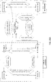
- FIG. 1 A constraint map of an unlimited roll handle assembly is shown in FIG. 1 , illustrating a conceptual model of the relative degrees of freedom (DoF) and degrees of constraint (DoC) between component portions of an unlimited roll handle rotation mechanism.
- the rotation mechanism typically comprises rigid bodies that are generically referred to as: H.Body A 101, H.Body B 102, H.Body C 103, and H.Body D 104.
- H.Body A may be referred to as the reference ground, in that the motion of all other bodies may be described with respect to H.Body A.
- H.Body A may be a palm grip.
- any other of these bodies may be used as the ground reference for describing the motion of the remaining bodies.
- H.Body C has a single translational degree of freedom (DoF) with respect to H.Body A along a first axis (e.g., axis 1) and has rotational constraint with respect to H.Body A about axis 1 105.
- DoF translational degree of freedom
- H.Body B has a rotational DoF with respect to H.Body A about axis 1 and has translational constraint with respect to body A along axis 1 106.
- H.Body D has single translational DoF with respect to H.Body B along axis 1 and rotational DoF constraint with respect to H.Body B about axis 1 107.
- H.Body D has rotational DoF with respect to H.Body C about axis 1 and translational constraint with respect to H.Body C along axis 1 108.
- FIG. 2 illustrates one example of an unlimited roll handle assembly fitting the constraint map shown in FIG. 1 .
- FIG. 2 shows H.Body A and H.Body B to be cylindrical in shape
- the schematic diagram of FIG. 2 does not depict the actual geometric features of each bodies, and these bodies can be of any general shapes as long as they satisfy the joint conditions/constraints between the various bodies as mentioned above.
- the constraint map of FIG. 1 results in the following functionality of the rotation mechanism shown: using H.Body A as a reference (i.e., assuming it to be stationary), this mechanism allows for the independent rotation of H.Body B with respect to H.Body A about Axis 1 111. While this happens, H.Body D rotates along with H.Body B, also about Axis 1 and since rotation of H.Body C is coupled to rotation of H.Body A, H.Body C does not rotate. At the same time, any axial translation of the non-rotating H.Body C with respect to the stationary H.Body A along Axis 1 is transmitted to H.Body D, even as H.Body B and H.Body D rotate about Axis 1.
- the joints within the rotation mechanism between the bodies that are constraining typically comprise interfacing geometries which prevent rotation or translation with respect to one another.
- this joint may be comprised of one or more cylindrical surfaces, and these surfaces can be enabled by a bearing, bushing, or lubricious surface treatment which minimizes frictional resistances.
- these surfaces may also comprise a lubricious surface treatment.
- H.Body D inherits the translation of H.Body C and the rotation of H.Body B.
- H.Body D has two DoF with respect to H.Body A, translation about Axis 1 and rotation about Axis 1. Any arbitrary combination of these two rotations gets separated into translation only at H.Body C and rotation only at H.Body B.
- any of the joints described herein may be encoded for transmission to an output (e.g., output joint).
- the encoding may be done mechanically, electrically, or otherwise.
- sensors may be positioned at these two bodies, e.g., a linear displacement sensor on H.Body C and a rotary sensor on H.Body B may give discrete/individual values for arbitrary combination of rotation and translation applied at H.Body D.
- These electrical signals could then be transmitted via wired or wireless means to a mechatronic, robotic, electronic, or computer-controlled system.
- actuators at these locations, e.g., a linear translational actuator between H.Body A and H.Body C and a rotary actuator between H.Body A and H.Body B. Any arbitrary discrete/individual motion inputs at these two bodies get added into a combined motion at H.Body D with respect to H.Body A.
- the encoding of movements at any of the joints described herein may be mechanically encoded, such as described below for an input joint encoding pitch and yaw by operating a pair of transmission strips coupled to pulleys to separately and mechanically encode pitch and yaw motions.
- other encoding techniques may alternatively or additionally be used.
- H.Body C is shown having a single translational DoF along axis 1 with respect to H.Body A and vice versa.
- H.Body C also has a rotational constraint along axis 1 with respect to H.Body A and vice versa.
- This type of joint, between bodies A and C can be accomplished through a variety of embodiments.
- the interfacing bodies have a keying feature between them which restricts (e.g., biases) rotation about axis 1 and simultaneously allows for translation along axis 1.
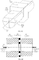
- FIG. 3A schematically describes a joint which might occur between H.Body A and H.Body C. Referring to FIG.
- an outer body with a square longitudinal slot may refer to H.Body A 301 while the inner square key may refer to H.Body C 303.
- H.Body A is fixed to reference ground
- H.Body C will be allowed to translate about axis 1 311 while unable to rotate about axis 1 due to the interferences posed by square cross-sectional joint.
- this joint can also have a rectangular cross-section which can provide the same single axis (axis 1) rotational constraint and single axis (axis 1) translational DoF.
- a functional aspect of this joint is a low friction relative sliding motion along axis 1 between H.Body A and H.Body C.
- the surface contact between both bodies need to be minimal so as to avoid large frictional contact between surfaces of H.Body A and H.Body C. Therefore, one way of achieving the same joint between H.Body A and H.Body C with less friction contact is to minimize the contact surface area between two bodies.
- FIG. 3B shows one way to reduce the surface contact between H.Body A 301 and H.Body C 303 by interfacing the spokes shown in FIG. 3B of H.Body C with slot cut out in H.Body A.
- FIGS. 3A and 3B show examples of achieving the constraint and DoF between H.Body A 301 and H.Body C 303 but, they can have different geometric shapes such that the constraints and DoFs are met.
- FIG. 3C shows one way this joint can be achieved by essentially providing the keying surface 320 via the flat end of the D-Shaft 303 (H.Body C) and the slot present in H.Body A 301.
- H.Body B 302 and H.Body D 304 have a rotational constraint about axis 1 311 and single translational DoF along axis 1 311. This is the same constraint and DoF that is present between H.Body A 301 and H.Body C 303. Therefore, each one of the ways to attain the joint between H.Body A and H.Body C are also applicable to the joint between H.Body B and H.Body D; given the constraint and DoF requirements are fulfilled.
- any of the Joints between H.Body A and H.Body C as well as between H.Body B and H.Body D may include or require a low friction surface contact between the bodies. This, along with rotational constraint about axis 1 and single translational DoF along axis 1, may completely define the joint between these bodies. Similarly, a constraint, a DoF and functional requirements define the joint between H.Body A and H.Body B as well as between H.Body C and H.Body D. H.Body A and H.Body B may have a single rotational DoF about axis 1 relative to each other and translational constraint along axis 1.
- H.Body A and H.Body B may also have a functional requirement of providing low friction joint between them while they rotate relative to each other about axis 1. This functional requirement comes from the fact that either of the duo, H.Body A and H.Body B or H.Body C and H.Body D can be under compressive or tensile loading while fulfill the rotational DoF about axis 1 and translational constraint along axis 1.
- H.Body A and H.Body B are placed such that their surfaces normal to axis 1 are under compression, they need to overcome the normal forces acting on each bodies' surfaces so as to provide rotational DoF about axis 1. Therefore, to provide rotational DoF about axis 1 and translational constraint along axis 1, the surfaces of H.Body A and H.Body B may need to provide low friction contact such that the bodies can rotate relative to each other about axis 1.
- FIG. 3D shows one way of obtaining the desired DoF and constraint by providing low friction surface contact.
- a thrust bearing 330 is used to provide the rotational DoF along with maintaining low friction contact between surfaces of H.Body A 301 and H.Body B 302 by holding the thrust load between the two bodies.
- this functionality can be achieved by fulfilling the DoF and constraint requirement.
- an angular contact ball bearing which can hold the thrust load or a roller ball bearing capable to hold the required thrust load can also be used between H.Body A and H.Body B or bushing between two bodies can be used to provide radial support as well as capacity to bear thrust load.
- FIG. 3E shows a thrust bearing 333 between H.Body A and H.Body B along with washers 334, 335 on each side of the bearing 333.
- FIG. 3E shows a single washer 340 between H.Body A 301 and H.Body B 302 made of material with low friction coefficient like Teflon (PTFE), nylon, etc. can also serve the purpose for bearing the thrust load and providing the rotational DoF about axis 1 311. This is shown in FIG. 3F .
- FIG. 3G shows a bushing 345 placed between the interfacing surfaces of H.Body A 301 and H.Body B 302 such that it is capable to holding thrust load and provide translational constraint along axis 1.
- FIG. 3H The same system of two bodies with an intermediate member carrying thrust load and providing rotational DoF about axis 1 311 and translational constraint along axis 1 311, shown in FIG. 3D , 3E, and 3F also works well when there is a tensile load as opposed to compressive load on H.Body A and H.Body B. This is depicted in FIG. 3H with a case similar to FIG. 3D where a thrust bearing 347 resides between H.Body A 301 and H.Body B 302, facing normal to axis 1 311.
- the bearing lying between H.Body A 30 1 and H.Body B 302 can be of different types, e.g., thrust needle bearing, thrust roller bearing, roller bearing, tapered roller bearing, angular contact bearing, etc.
- FIG. 31 shows a thrust roller bearing 347 acting as joint between H.Body A 301 and H.Body B 302.
- H.Body A and H.Body B may have the same joint as H.Body C 303 and H.Body D 304 and comply with all the aforementioned joint types mentioned in this section.
- tapered roller bearings 349 In addition to thrust bearings, one can also employ tapered roller bearings 349, radial ball bearings, etc. One may also employ a combination of these bearings. Some examples are shown in FIGS. 3J and 3K .
- H.Body A 301 and H.Body B 302 can be under compressive or tensile load along axis 1.
- H.Body C 303 and H.Body D 304 can also be under compressive or tensile load along axis 1.
- H.Body A 301 and H.Body B 302 or H.Body C 303 and H.Body D 304 can be under tensile or compressive load.
- H.Body A may serve as the reference ground. Therefore, H.Body B can be under tension or under compression with respect to H.Body A.
- H.Body C is free to move along axis 1 with respect to H.Body A and has rotational constraint about axis 1 with respect to H.Body A.
- H.Body C can be under compression or tension with respect to H.Body D.
- H.Body D is free to translate along axis 1 with respect to H.Body B and has rotational constraint about axis 1 with respect to H.Body B.
- H.Body B is under compressive load with respect to H.Body A and H.Body C is under tensile load with respect to H.Body D is show in FIG. 3L .
- an angular contact bearing 351 between H.Body A 301 and H.Body B 302 is used. This accounts as a joint between H.Body A 301 and H.Body B 302 which accomplishes the constraint and DoF requirement mentioned above along with the functional requirement of providing low friction surface contact.
- a thrust bearing between H.Body C 303 and H.Body D 304 may be used. This accounts as a joint between H.Body C 303 and H.Body D 304 which accomplishes the constraint and DoF requirement mentioned above, along with the functional requirement of providing low friction surface contact.
- the constraint map ( FIG. 1 ) doesn't imply any restriction on geometric shapes of these bodies as far as the functionality, DoFs and constraints are met.
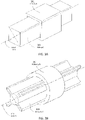
- FIGS. 4A and 4B show an example of an ergonomic handle assembly (unlimited rotation handle assembly) that utilizes the mechanism described in FIG. 3L involving compressive and tensile loading conditions.
- This handle is an embodiment of the constraint map shown in FIG. 1 .
- the rotation dial (H.Body B 402) is under translational constraint about axis 1 411 with respect to Handle Body Shell (H.Body A 401).
- the rotation dial transmits this rotation about axis 1 411 to H.Body D 404, which is referred as shuttle 404. This is possible because shuttle (H.Body D) is under rotational constraint about axis 1 411 with respect to rotation dial (H.Body B 402) and therefore, has no relative rotation about axis 1.
- the shuttle (H.Body D 404) is further interfaced with H.Body C 403 (referred as push rod or pull rod) via a joint which allows translational DoF along axis 1 and rotational constraint about axis 1.
- the translation of shuttle (H.Body D) along axis 1 is further transmitted to the moving jaw in the end-effector via the jaw closure transmission member.
- An end-effector transmission 455 may alternatively be referred to (e.g., when the end-effector is configured as a jaw) as a jaw closure transmission member 455 or jaw closure actuation transmission member to describe the same transmission member; in some variation it may simply be referred to as a transmission cable (when it is a compliant cable, for example).
- This jaw closure actuation transmission member 471 can be either rigid or non-rigid body or a combination of a rigid and non-rigid members.
- the transmission member can be the shaft of an apparatus (e.g., of a laparoscopic instrument) or a rod passing internally through the shaft or can be a cable under tension that connects to the end-effector at the distal end of the laparoscopic instrument or it can be combination of a non-rigid and a rigid body (a rod along with a cable under tension).
- the push/ pull rod (H.Body C 401) and shuttle (H.Body D 404) are under tensile load and the rotation dial (H.Body B) is under compressive load and does not translate along axis 1 411 with respect to handle shell (H.Body A) 401.
- FIG. 4A and 4B can be constructed via a flexure-based design, also known as a compliant mechanism, that realizes the the constraint map of FIG. 1 by employing compliant or flexure joints between the bodies H.Body A, H.Body B, H.Body C, and H.Body D to achieve the necessary constraints.
- a flexure-based design also known as a compliant mechanism
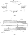
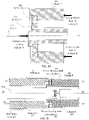
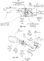
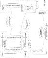
- FIGS. 5 and 7 An apparatus including the unlimited roll handle assemblies shown in FIGS. 4A and 4B above is shown in FIGS. 5 and 7 as part of a medical device (specifically a laparoscopic device).
- FIGS. 5 and 7 shows a laparoscopic surgical instrument having an end-effector configured as a jaw assembly; in FIG. 5 the jaws are open and in FIG. 7 the jaws are shown closed.
- the exemplary apparatus includes a tool frame 525, which includes a tool shaft 526 and a forearm attachment portion at the proximal end 527.
- a cuff (not shown) having a passage therethrough that is configured to hold a wrist or forearm of a user may be coupled to the forearm attachment portion; in some variations via a bearing between the forearm attachment portion of the frame and the cuff that is configured to slide or roll so that there is a roll rotational degree of freedom between the frame and the cuff about the tool axis.
- a proximal unlimited roll handle assembly such as the ones shown in FIG. 4A and 4B may be connected to the tool frame by an input joint.
- the input joint may be configured to encode motion between the tool frame and the handle assembly, as shown in FIG. 5 .
- the input joint includes a pair of transmission strips 533, 534 that connect to respective pivoting joints (not shown) in parallel to separately encode pitch and yaw rotations of the handle assembly.
- An output joint 583 (shown as an end-effector articulation joint) between the end-effector and the tool frame (e.g., tool shaft) receives transmission input (e.g., cables, not shown) from the output joint 533, 534 to articulate the end-effector.
- the handle assembly includes an ergonomic palm grip portion 501 (handle shell) that connects to the rotation dial 502, which enclose an internal push rod and shuttle (not visible); these four elements are constrained per the constraint map shown in FIG. 1 .
- the handle assembly also includes an end-effector control 549 input (in this example, defining the end-effector jaw closure input 549) that is configured as a handle lever and acts as a rigid extension of the internal push rod.
- the handle lever is coupled to the push rod via a transmission mechanism that may comprise a linkage, cams, springs, etc.
- a transmission cable 566 connects to the shuttle and acts as a jaw closure actuation transmission member extending from the shuttle and through the tool shaft to the end-effector.
- This transmission cable may be enclosed by a protective and/or supporting sheath or cover or conduit, for some or entire portion of its length.
- the end-effector itself is a jaw assembly including a first (ground) end-effector portion, in this example, including a fixed jaw 569 to which a pivoting second end-effector portion (moving jaw 568) is attached.
- the transmission cable 566 may couple to the moving jaw at the end-effector closure output 577.
- the handle may rotate about first axis 511 referred to as handle articulated roll axis (axis 1), to cause the tool shaft to rotate in a third axis 515 referred to as the tool shaft roll axis (axis 3), in turn causing the end-effector to roll about a second axis, referred to as an end-effector articulated roll axis (axis 2).
- the rotation dial 502 (H.Body B) as shown in FIG. 5 is rotated about axis 1 511.
- the rotation of H.Body B leads to rotation of tool frame 525 via transmission strips 533, 534 (as they constrain rotation DoF), tool shaft 526 (about axis 3 515) and therefore, the end-effector (about axis 2 513).
- the end-effector articulates via output articulating joint.
- the center axis (axis 2) for end-effector is different from the axis 3, the shaft axis.
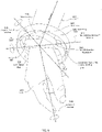
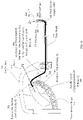
- FIG. 6 illustrates an example of a forearm attachment component that may be used.
- the forearm attachment comprises a 3-Axis gimbal assembly including a wrist cuff 605 that securely attaches to the user's wrist/forearm 607, 608, leaving their hand 609 free to move (e.g., to grasp the handle and manipulate the rotating dial and end-effector control input).
- the forearm attachment allows pitch, yaw and roll degrees of freedom; the cuff attaches to a deviation ring 514 that is pinned to rotation about flexion/extension axis of rotation 516.
- the deviation ring is itself coupled in a pivoting axis (deviation axis of rotation 521) to a sled 518 which rolls around a raised inner track 519 of an outer guide ring 520, rolling about a roll axis of rotation 531.
- This assembly provides pitch, yaw and roll degrees of freedom when coupled to the apparatus tool frame; for example, the outer guide ring maybe formed as part of the forearm attachment portion of the apparatus, or it may be attached thereto.
- the cuff may releasably couple into the rest of the forearm attachment apparatus via a snap-fit 540 or other coupling.
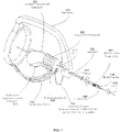
- FIG. 8 shows another view of the laparoscopic instrument of FIGS. 5-7 in an articulated position holding a needle that may be used to suture tissues.
- the end-effector fixed jaw (ground) and end-effector moving jaw can be rotated about axis 2 such that the tool shaft/tool frame rotates about axis 3 while the handle is rotated about axis 1; all while holding the needle securely by moving the end-effector moving jaw with respect to an end-effector fixed jaw via a jaw closure actuation transmission member connected to H.Body D at the proximal end of the device.
- the apparatus shown in FIGS. 5-8 may fit a constraint map such as the one shown in FIG. 20A .
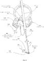
- FIG. 9 Another variation of an apparatus that conforms to the constraint map described in FIG. 1 is shown in FIG. 9 .
- the rotation of rotation dial 902 H.Body B
- axis 1911 leads to rotation of the end-effector assembly (shown here as a jaw assembly including a moving jaw 968 and a fixed jaw 969) about axis 2 915.
- the tool frame 925 including the tool shaft 926 does not rotate about either their axis (axis 3 915).
- the tool frame may still be connected to a cuff mounted on a user's forearm via a forearm attachment joint that may provide a pitch and/or yaw rotational DoF.
- the end-effector assembly has a rotational DoF with respect to the distal end of the end-effector articulation output joint about axis 2 (similar to that between H.Body A 901 and H.Body B 902 about axis 1) and the end-effector rotation transmission member 950 connects H.Body B directly to the end-effector assembly via a torsionally stiff end-effector rotation transmission member 950.
- This may also be the jaw closure actuation transmission member or may house and therefore route, a flexible jaw closure actuation transmission member, for example, a flexible shaft (end-effector rotation transmission member) that is torsionally stiff to transmit rotation from one end to another housing a flexible cable (jaw closure actuation transmission member) inside it.
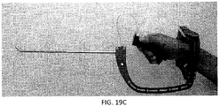
- FIG. 10 Another example of an apparatus using the unlimited roll handle apparatuses described herein is shown in FIG. 10 .
- This apparatus is configured as a straight stick device with a non-articulating end-effector; other straight stick apparatuses are described in US 4,712,545 , US 5,626,608 , and US 5,735,874 ; such apparatuses may benefit from any of the unlimited roll handle apparatuses such as those shown in FIGS. 4A and 4B .
- FIG. 10 shows an example of a surgical instrument consisting a handle assembly (including palm grip portion 1001 and a dial portion 1002), tool shaft 1026 and an end-effector 1068.
- the end-effector connects to the rotation dial 1002 (H.Body D) via a jaw closure actuation transmission member (not visible in FIG. 10 ).
- This instrument provides the functionality of closing and opening the end-effector by moving the moving jaw relative to the fixed jaw. It may also provide the rotation of the end-effector about the handle axis (axis 1 1011); the shaft axis 1015 (axis 3) is parallel to the handle axis 1 1011 via rotation of H.Body B 1002, tool shaft 1026 and therefore, the end-effector 1068.
- FIG. 11 shows an articulating laparoscopic device.
- Such devices include a handle, tool shaft 1126 and an articulating end-effector 1168, 1169. Similar to non-articulating laparoscopic instrument, these also contain an end-effector rotation joint (open/close functionality) between moving jaw 1 168 and a fixed jaw 1169. But, in addition to this open/close joint, these also contain an output articulation joint 1143 for end-effector articulation and an input articulation joint 1 142.
- This input articulation joint maybe a serial kinematic (S-K) or parallel kinematic (P-K).
- S-K serial kinematic
- P-K parallel kinematic
- Some articulating instruments that consist of S-K input joint can be found, for example, in U.S. 8,465,475 ; US 5,713,505 , US 5,908,436 , US application no. 11/787,607 and US 8,029,531 .
- Examples of parallel kinematic input joint based articulating instruments may be found, for example, in US 2013/0012958 .
- the end-effector may be a jaw assembly and may be shown to be open jaw condition but it can perform rotation using end-effector rotation joint even in closed jaw condition as well as in articulated condition.
- FIGS. 12 and 13 illustrate other unlimited roll handle assembly variations that follow the constrained map illustrated in FIG. 1 .
- These handle variations may be used with any of the other apparatus components described herein (including with other device architectures and/or constraint maps).
- the rotation dial 1202 is proximal to the palm grip portion 1201.
- the apparatus may include a shaft 1226 and end-effector 1265, and may include the same axes as described above (first axis 1211, second axis 1213 and third axis 1215).
- joint characteristics (DoFs and DoCs) between H.Body A and H.Body C are the same as the ones between H.Body B and H.Body D.
- FIG. 13 shows a different location where the reference ground is located in the handle assembly.
- H.Body B is chosen as reference ground and interfaces firmly with user's hand, whereas, H.Body A is rotated with respect to H.Body B.
- H.Body C rotates with respect to H.Body D and H.Body C.
- Another way of explaining this embodiment is that the handle's rear end is now placed at the proximal end and vice versa.
- any of the apparatuses described herein may include a rotation lock/ratcheting mechanism, as illustrated in FIG. 13 .
- the handle assembly shown by the constraint map of FIG. 1 consists of a joint between H.Body A and B which provides rotational DoF about axis 1. This rotation can be made more tactile by application of ratcheting feature between H.Body A and H.Body B, as shown in FIG. 3B . Ratcheting between H.Body A and H.Body B can provide a sense of discrete rotation degrees while rotating about axis 1.
- FIG. 13 illustrates a similar variation.
- a thrust bearing 1317 is located between the palm grip 1301 and the rotation dial 1302, as is a ratchet mechanism 1319.
- the shuttle 1304 and push rod 1303 otherwise operate per the constrained diagram of FIG. 1 .
- the handles described herein may also be used with an apparatus configured to provide a pecking motion at an end-effector using these handle mechanisms.
- the handle mechanism (fitting the constrained map of FIG. 1 ) may show the opening and closing of an end-effector jaw triggered directly by radial pressing of the rotation dial (H.Body B) 1402.
- the device described in FIG. 15 consists of a handle shell (H.Body A) 1401, rigidly attached to the hands of the user. Further, it may include a rotation dial 1402 (H.Body B) which can rotate relative to handle shell (H.Body A) about axis 1 1411.
- This sleeve which is the shuttle, leads to the opening and closing of the end-effector, making it act as a double action jaw which can have different applications in open surgery like eye surgery and minimal invasive surgery.
- push/ pull rod H.Body C, which can't be seen in FIG. 14
- H.Body C which can't be seen in FIG. 14
- spring such that when the push/ pull rod moved relative to handle shell, it retracts back to its original position with the help of the spring.
- this embodiment represents a device which can rotate the end-effector about its normal axis (axis 1) and help in securement of respective external bodies in the end-effector by pecking the shuttle to cause opening/closing of the end-effector
- FIG. 15 is another example of an apparatus as described herein, configured as a Pull-Pull configuration for jaw closure transmission.
- This example includes an unlimited roll handle assembly such as was shown in FIG. 4A , including a shuttle 404 H.Body D keyed to H.Body B 402.
- the jaw closure transmission member 1530 is pulled to close the end-effector moving Jaw 1567 with respect to end-effector fixed jaw 1568 and is pulled to open the moving Jaw with respect to fixed jaw.
- the jaw closure (open/close) actuation transmission member 1530 is attached to H.Body D 404, where H.Body D can translate with respect to H.Body B 402 due to DoC in translation along axis 1 411 with respect to H.Body C 403.
- a second jaw closure (open/close) actuation transmission member 1532 is pulled to open the end-effector moving jaw.
- this transmission member can be pulled using a pull spring 1513, grounded at a reference frame called "Spring Reference Ground”.
- "Spring Reference Ground” can occur at different locations in the assembly, as described below: (1) by means of input art joint, tool frame/shaft, output articulating joint (the “spring reference ground” can occur at H.Body B or tool frame/ tool shaft or fixed jaw); (2) by means of an independent roll transmission member routed across the input art joint, through tool frame/shaft, and output articulating joint. Extra roll DoF between output joint distal end and end-effector base (the "spring reference ground” can occur at H.Body B or at the end-effector fixed jaw).
- the unlimited roll handle assembly is generally configured to include a forearm attachment apparatus.
- the unlimited roll handle apparatus may provide the ability for the apparatus to simultaneously transmit roll and closure action to Body D with respect to Body A.
- a forearm attach member with DoF was described above in FIGS. 5-8 , and another example is shown in FIG. 16 .
- a (one) joint exists between the wrist attachment/wrist cuff 1609 and the tool frame 1625, referred to as a forearm attach joint.
- a forearm attach joint may be used to couple the wrist attachment/wrist cuff and tool frame, allowing zero or one or more DoF between the arm and the apparatus.
- Some variations may be articulating or non-articulating devices that are forearm mounted.
- one embodiment can include a roll DoF by providing a rotation joint between the wrist attachment and tool frame. This joint may use a "sled" (see FIG. 6 ) which can allow rotational DoF about the arm axis.
- Another embodiment can involve a pitch DoF by providing a rotation joint allow rotation about flexion/extension axis of rotation.
- a yaw DoF by providing a rotation joint allow rotation about deviation axis of rotation.
- Another embodiment can involve both pitch and yaw DoF by providing a rotation joint allow rotation about flexion/extension axis of rotation and deviation axis of rotation respectively. This may use another body called deviation ring (see FIG. 6 ).
- FIG. 16 Another embodiment can involve roll (about arm axis), pitch (about flexion/extension axis of rotation) and yaw (about deviation axis of rotation) DoF.
- a joint may exist between tool frame and tool shaft, called a shaft-frame joint.
- This shaft-frame joint may have zero DoF (rigid connection between shaft and frame), which is the default configuration considered in this discussion.
- the device in FIG. 16 includes a handle palm grip 1601 (H.Body A), a rotation dial 1602 (H.Body B) and an end-effector input 1612, a shaft-frame joint 1615, an end-effector 1668 at a distal end of the tool shaft 1626.
- the apparatus also includes a handle axis, axis 1 1611, tool shaft axis, axis 3 1615 and an end-effector axis, axis 2 1613.
- a non-articulating instrument that is forearm mounted and that has an unlimited roll handle assembly may include a separate tool frame and tool shaft.
- the tool frame and wrist cuff may be rigidly attached (0 DoF).
- the apparatus may be configured so that there is at least one roll rotation DoF between the tool shaft and tool frame.
- a shaft-frame joint can have roll DoF, Pitch DoF, Pitch and/or Yaw DoF.
- any of the apparatuses including an unlimited roll handle described herein may also include a virtual center (VC) at the input articulation joint as shown in FIG. 17 .
- This device can have serial or parallel kinematic input joint with joint axis intersecting at a virtual center.
- This device is similar to that shown in FIG. 5 , but shows the virtual center 1721.
- the device includes an end-effector assembly 1768 that is also configured as a jaw assembly.
- FIGS. 18A-18D illustrate one example of a medical device configured as a laparoscopic apparatus including an unlimited roll (unlimited roll) handle, an elongate tool frame, a forearm attachment having multiple degrees of freedom between the user's arm and the tool frame, an end-assembly configured as a jaw assembly and an input joint that encodes pitch and yaw rotation of the handle for transmission to an output joint so that the end-effector may articulate as the handle does.
- FIGS. 19A-19C A schematic constraint diagram for the apparatus show in FIGS. 18A-18D is shown in FIG. 20A .
- An alternative constraint diagram for an apparatus as described herein is shown in FIG. 20B .
- the overall device comprises a pulley block 1805, a tool frame 525 including a tool shaft 526 (the tool shaft may be considered a portion of the tool frame), all rigidly inter-connected.
- the pulley block serves as the outer ring 1805 of a forearm attachment apparatus/joint that interfaces with the distal forearm of a user via a wrist cuff 1803, as described above.
- the wrist cuff 1803 and outer ring are all part of the forearm attachment apparatus/joint.
- the forearm attachment joint comprises an outer ring, a roll ring, a deviation ring, and the wrist cuff (all connected in series), as described in FIG. 6 , and provide three rotational degrees of freedom (DoF) between the wrist cuff and the outer ring.
- These three rotations may be defined as roll, pitch, and yaw.
- Roll is the rotation direction about the axis of the outer ring, which is the same as the axis of the tool shaft.
- Pitch and yaw are orthogonal rotations with respect to the roll rotation, as shown in some of the figures.
- the forearm attachment joint provides the above three rotational DoF between the tool frame and user/surgeon forearm.
- the tool frame extends from the outer ring / pulley block, and is shaped around the handle assembly to accommodate a user's hand (over its entire range of articulation) while holding the handle assembly.
- the tool frame rigidly connects to a tool shaft, which further extends towards the distal direction (i.e., away from the forearm attachment joint and the user).
- a two-DoF articulating joint also referred to as the output joint /end-effector articulating joint.
- These two degrees of freedom are pitch and yaw rotations, which are controlled/actuated by articulating a device input joint (discussed below) between handle assembly and the pulley block.
- the end-effector is equipped with a pair of jaws that can be opened and closed in response to a handle lever that is part of the handle assembly at the device input (discussed below).
- the input joint of the device is a parallel kinematic mechanism comprising two flexure transmission strips and two transmission pulleys (pitch pulley and yaw pulley).
- the overall device geometry is such that the Virtual Center produced by the parallel kinematic input joint coincides with the center of rotation the user's wrist joint. This ensures a natural, comfortable, unrestricted articulation of the surgeon's wrist while using the device.
- the yaw and pitch rotations of the user's wrist with respect to his forearm are translated to the corresponding rotations of the handle assembly with respect to the tool pulley block / tool frame.
- the parallel kinematic design of the virtual center / input mechanism is such that the two rotations (pitch and yaw) of the handle with respect to the pulley block are mechanically separated/filtered into a pitch only rotation seen at the pitch pulley and yaw only rotation seen at the yaw pulley.
- the pitch pulley and yaw pulley 1813 are pivoted (and mounted) with respect to the pulley block about the pitch rotation and yaw rotation axes, respectively.
- the input joint In addition to the yaw and pitch rotational DoF provided by the input joint, it also provides/allows axial translational DoF along the roll axis. This allows a range of user hand sizes to be accommodated in the device and ensures free and unrestricted hand/wrist articulation.
- the transmission strips are stiff in twisting about the roll axis. This ensures that the input mechanism constrains (and therefore transmits) roll rotation from the distal end of the handle assembly (i.e., the dial) via the transmission strips to the pulley block.
- pulley block serves as the outer ring of the forearm attachment apparatus which provides a well-defined low-resistance rotation about roll axis 1835 with respect to the wrist cuff. This implies that when the user holds the handle in his palm, he can articulate the handle in any desired yaw and pitch directions, resulting in corresponding articulation of the end-effector. Then he can twirl the dial of the handle assembly with his thumb and fingers (typically index finger) while keep the handle articulation fixed.
- the twirling of the dial (i.e., roll rotation) is transmitted to the pulley block / outer ring via the parallel kinematic input joint (i.e. flexure transmission strip based virtual center mechanism).
- the pulley block then rotates about the roll axis with respect to the wrist cuff, which is attached to the forearm of the user.
- the entire tool frame rotates about the roll axis with respect to the forearm of the user.
- the shaft Since the shaft is rigidly connected to the tool frame, the shaft also rotates about the roll axis 1835.
- the roll rotation of the tool shaft is transmitted to the end-effector as well via the output joint (i.e. end-effector articulating joint).
- the handle assembly comprises a dial and a handle, which are connected by a handle rotation joint which has a single rotational DoF about the roll axis.
- the handle also houses a handle mechanism with a handle lever; as the handle lever is depressed (by the user's fingers, typically middle, ring, and pinky fingers) with respect to the handle, the handle mechanism translates this action into a pulling action of a cable.
- This pulling action is transmitted via the rotating interface/joint between the handle and the dial.
- This pulling action exerted on a jaw closure cable is then transmitted to the end-effector via flexible conduit between the dial and tool frame, and then via the tool shaft, via the end-effector articulating joint, all the way to the end-effector jaws.
- a jaw closure mechanism in the end-effector converts the pulling action of the cable into jaw closure action, as would be needed in shears, graspers, needle-holder, etc.
- the virtual center provided by the device input joint coincides with the center of rotation of the wrist joint of the user operating the device.
- the three rotational axes of the three DoF (yaw 1831, pitch 1833, and roll 1835 rotations) provided by the forearm attachment joint may all intersect at one point, referred to as the center of rotation of the forearm attachment joint.
- This center of rotation of the forearm attachment joint may coincide with the center of rotation of the device input joint (i.e. the virtual center of rotation of the handle with respect to the pulley block).
- center of rotation of the forearm attachment joint may also coincide with the center of rotation of the user's wrist joint when the device is mounted on a user forearm.
- the forearm axis should coincide with the axis of the outer ring, which should coincide with the axis of the tool shaft, which should coincide with the axis of the end-effector.
- the handle is not articulated with respect to the pulley block (i.e. is nominal) and therefore the end-effector is not articulated with respect to the tool shaft.
- the overall weight of the device may be distributed such that its center of gravity lies close to the roll axis of the device. This ensures that as the user rolls the device (as described above) he is not working with or against gravity. With the weight of the device supported at the user's forearm and a trocar on the patient's body, locating the center of gravity of the device on the roll axis makes driving the roll rotation relatively effortless because gravity no longer plays a role during the roll rotation.
- the overall device design and construction also helps filter out hand tremors and prevent them from reaching the end-effector.
- the handle and therefore surgeon's hand are isolated from the pulley block / tool frame / tool shaft by means of the transmissions strips.
- These flexure transmission strips because of their material and/or construction, prevent any hand tremors from reaching the tool shaft and end-effector.
- the tool frame is mounted on the forearm via the forearm attachment joint. Therefore the tool shaft, which is connected to the frame, is controlled by the forearm of the surgeon. Not only does this help drive power motions (translating the tip of the shaft in three directions), but the forearm has much less tremors compared to the hand and therefore the shaft sees less tremors as well.
- the transmission strips may help separate out and transmit the yaw and pitch rotations of the handle with respect to the pulley block (equivalently, the yaw and pitch rotations of the hand with respect to the forearm) to pitch and yaw transmission pulleys, which are mounted on the pulley block. They also help transmit the roll rotation from the handle assembly to the pulley block, tool frame, tool shaft, all the way to the end-effector. They also help filter out or block hand tremors from reaching the pulley block, and therefore the tool frame, and therefore the tool shaft, and therefore the end-effector.
- the use of a rotating handle mechanism enables surgeons to have better control with the surgical instrument during surgery. Better control is a result of being able to transfer natural, ergonomic, and intuitive motion from the surgeon's hand/wrist/forearm to the end-effector.
- the virtual center mechanism allows a mapping of pitch and yaw rotations of the surgeon's wrist to be transferred intuitively and fluidly to corresponding rotations of the end-effector articulating joint. Without the rotating handle mechanism to perform a roll of the end-effector the surgeon is limited to pronation and supination of his forearm which has a limit to the amount of roll that can be biomechanically achieved.
- pronation and supination are combined with flexion and extension of the wrist. Due to the limitations in the human body this rotation in limited in both total roll angle as well as the offset angle from surgeon's wrist axis. Pronation, supination, flexion, and extension of the wrist all have various maximum articulation angles therefore to perform an articulated roll where the axis of the roll remains constant the angle of the roll will be limited to the by the maximum angle the hand can make with wrist in the worst possible orientation.
- the surgical instruments described herein are able to intuitively, fluidly, and ergonomically have the end-effector directly inherit or achieve yaw, pitch, and roll that is observed at the input of the device.
- roll is also transferred to the end-effector with the rolling of the handle dial.
- the surgeon is able to ergonomically perform an articulated roll by keeping the wrist fixed and rolling the handle dial with their thumb/fingers. This enables an articulated roll in every orientation of the wrist with the roll angle being only limited to that specific orientation of the wrist.
- the roll of the end-effector is no longer limited in rotation by the surgeon's limitation in pronation, supination, flexion, and extension.
- the surgeon is able to perform an INFINITE amount of roll while still being able to use the handle actuation input (i.e. lever) to control the open/close actuation of the end-effector in any articulation or roll orientation.
- the unlimited roll handle assemblies described herein enable simultaneous and predictable control of all the minimal access tool's advanced features with an ergonomic interface.
- This handle features power motions, finesse motions and intuitive control of articulation. These three actions are individually aligned to optimal regions of the user's hand. Power motions such as gripping the handle and lever to close the jaw are confined to the palm and rear fingers. Finesse motions such as rotating the dial are aligned to the thumb and first fingers (e.g., index finger). The separation of power and finesse actions to these regions of the hand minimizes user fatigue. This also reduces the cognitive load for the user, reducing their mental fatigue. Similar to using a computer joystick, articulation is controlled by gently directing the handle to the desired angle.
- the unlimited roll handle apparatuses described herein enable the simultaneous actions of open/close, roll rotation and articulation (or any combination). Like our own hand, motions are fluid and natural. Performing a "running stitch" by rotating the dial in continuous direction without unwinding, unlocking or other intermediate step is a novelty compared with other suturing instruments. This is made possible by balancing the instrument and simplifying the mechanics of instrument rotation. When the dial on the handle is rotated, the entire instrument rotates or orbits in the same direction around the user's wrist. During this process, the virtual center also rotates but remains focused at the center of the user's wrist. Consequently, performance is consistent and predictable, even during complex moves like an articulated axial rotation.
- the handles described herein enable a finesse roll of the handle while engaging the closure mechanism.
- the rotation mechanism within the handle as previously described comprises optimized bearings between the various bodies within the mechanism. It is by way of the bearings between various bodies of the rotation mechanism that the surgeon does not notice any difference in the resistance to rotate when the jaw closure lever is engaged or disengaged. Infinite rotation of the handle is enabled by a swivel joint and several keying features within the rotation mechanism which prevent the jaw closure cable from twisting upon itself during rotation.
- these handles may allow the surgeon to perform an articulation of the end-effector of the overall surgical device by articulating their own wrist while comfortably holding the base of the handle and closure lever.
- Articulation of the unlimited roll handle apparatus leverages the distal end of the rotation knob to drive the transmission strips about their articulation pulleys centered over the surgeon's wrist, also known as the virtual center mechanism. Actuation of these two pulleys drives articulation cables through the frame to control the corresponding articulation of the end-effector. Once an articulated position is established, the surgeon may choose to close the jaw by activating the closure lever on the handle.
- the process of driving a needle requires that the surgeon roll rotate the end-effector about its articulated axis therefore driving the needle about its curvature axis through various tissue planes.
- These handles may (in conjunction with the other features described herein) provide the surgeon with easy access to the rotation knob where rotation of this mechanism will drive rotation of the transmission strips and the articulation pulleys about the surgeon's wrist as enabled by the three-axis wrist gimbal (i.e. the forearm attachment joint).
- the wrist gimbal constrains and centers the device about the surgeon's wrist so that rotation of the rotation knob (i.e. dial) and VC mechanism drives a predictable concentric rotation of the pulley block, frame, tool shaft and end-effector about the surgeon's wrist.
- These devices enable finesse rotation control and minimize resistances to rotation located in the handle rotation mechanism (addressed via bearings) and at the wrist gimbal (addressed via minimized contact surfaces and low friction plastic materials), overall balance of the device (addressed by establishing a center of gravity on the axis of rotation and redistribution of weight throughout the device), and the use of transmission strips which offer little compliance in torsion/twisting about roll axis.
- references to a structure or feature that is disposed "adjacent" another feature may have portions that overlap or underlie the adjacent feature.
- the device may be otherwise oriented (rotated 90 degrees or at other orientations) and the spatially relative descriptors used herein interpreted accordingly.
- the terms “upwardly”, “downwardly”, “vertical”, “horizontal” and the like are used herein for the purpose of explanation only unless specifically indicated otherwise.
- first and second may be used herein to describe various features/elements (including steps), these features/elements should not be limited by these terms, unless the context indicates otherwise. These terms may be used to distinguish one feature/element from another feature/element. Thus, a first feature/element discussed below could be termed a second feature/element, and similarly, a second feature/element discussed below could be termed a first feature/element without departing from the teachings of the present invention.
- any of the apparatuses and methods described herein should be understood to be inclusive, but all or a sub-set of the components and/or steps may alternatively be exclusive, and may be expressed as “consisting of” or alternatively “consisting essentially of” the various components, steps, sub-components or sub-steps.
- a numeric value may have a value that is +/- 0.1% of the stated value (or range of values), +/- 1% of the stated value (or range of values), +/- 2% of the stated value (or range of values), +/- 5% of the stated value (or range of values), +/-10% of the stated value (or range of values), etc.
- Any numerical values given herein should also be understood to include about or approximately that value, unless the context indicates otherwise. For example, if the value "10" is disclosed, then “about 10" is also disclosed. Any numerical range recited herein is intended to include all sub-ranges subsumed therein.
Claims (17)
- Dispositif médical, le dispositif comprenant :un effecteur terminal (1068, 1168, 1265, 1668) à une extrémité distale d'une armature d'outil oblongue (525, 925, 1625) ;une poignée qui fournit un roulis illimité à un effecteur terminal, dans lequel la poignée inclut :une première partie de poignée (101, 301, 401, 501, 901, 1001, 1201, 1301, 1401, 1601),une seconde partie de poignée (102, 302, 402, 502, 902, 1002, 1202, 1302, 1402, 1602) couplée à la première partie de poignée (301, 501, 1001, 1201, 1301, 1601) pour que le second corps de poignée (102, 302, 402, 502, 902, 1002, 1202, 1302, 1402, 1602) ait un degré de liberté de rotation dans un premier axe relativement à la première partie de poignée (101, 301, 401, 501, 901, 1001, 1201, 1301, 1401, 1601) mais soit limité en translation relativement à la première partie de poignée le long du premier axe (111, 311, 411, 511, 911, 1011, 1211, 1411, 1611),une tige-poussoir (103, 303, 403, 1303) à l'intérieur de la première partie de poignée (101, 301, 401, 501, 901, 1001, 1201, 1301, 1401, 1601) et couplée à la première partie de poignée (101, 301, 401, 501, 901, 1001, 1201, 1301, 1401, 1601) pour qu'elle ait un degré de liberté de translation le long du premier axe (111, 311, 411, 511, 911, 1011, 1211, 1411, 1611) relativement à la première partie de poignée (101, 301, 401, 501, 901, 1001, 1201, 1301, 1401, 1601) mais soit limitée en rotation autour du premier axe (111, 311, 411, 511, 911, 1011, 1211, 1411, 1611) relativement à la première partie de poignée (101, 301, 401, 501, 901, 1001, 1201, 1301, 1401, 1601),un corps-navette (104, 304, 404, 1404) à l'intérieur de la seconde partie de poignée (102, 302, 402, 502, 902, 1002, 1202, 1302, 1402, 1602), dans lequel le corps-navette (104, 304, 404, 1404) est couplé à la tige-poussoir (103, 303, 403, 1303) pour qu'il ait un degré de liberté de rotation autour du premier axe (111, 311, 411, 511, 911, 1011, 1211, 1411, 1611) relativement à la tige-poussoir (103, 303, 403, 1303) mais soit limité en translation le long du premier axe (111, 311, 411, 511, 911, 1011, 1211, 1411, 1611) relativement à la tige-poussoir (103, 303, 403, 1303), dans lequel en outre le corps-navette (104, 304, 404, 1404) est couplé à la seconde partie de poignée (102, 302, 402, 502, 902, 1002, 1202, 1302, 1402, 1602) pour qu'il ait un degré de liberté de translation le long du premier axe (111, 311, 411, 511, 911, 1011, 1211, 1411, 1611) relativement à la seconde partie de poignée (102, 302, 402, 502, 902, 1002, 1202, 1302, 1402, 1602) mais soit limité en rotation autour du premier axe (111, 311, 411, 511, 911, 1011, 1211, 1411, 1611) relativement à la seconde partie de poignée (102, 302, 402, 502, 902, 1002, 1202, 1302, 1402, 1602), etune entrée de commande d'effecteur terminal (549, 1612) sur la première partie de poignée (101, 301, 401, 501, 901, 1001, 1201, 1301, 1401, 1601), couplée à la tige-poussoir (103, 303, 403, 1303) et configurée pour translater la tige-poussoir (103, 303, 403, 1303) le long du premier axe (111, 311, 411, 511, 911, 1011, 1211, 1411, 1611),dans lequel la rotation de la seconde partie de poignée (102, 302, 402, 502, 902, 1002, 1202, 1302, 1402, 1602) est transmise à l'effecteur terminal (1068, 1168, 1265, 1668) pour que l'effecteur terminal (1068, 1168, 1265, 1668) entre en rotation avec la seconde partie de poignée (102, 302, 402, 502, 902, 1002, 1202, 1302, 1402, 1602);un élément de transmission d'actionnement d'effecteur terminal (950, 1530) destiné à transmettre l'actionnement de l'entrée de commande d'effecteur terminal (549, 1612) à l'effecteur terminal (1068, 1168, 1265, 1668).
- Dispositif selon la revendication 1, dans lequel l'effecteur terminal (1068, 1168, 1265, 1668) inclut une première partie d'effecteur terminal (568, 968, 1168, 1567) qui est couplée de façon mobile à une deuxième partie d'effecteur terminal (569, 969, 1169, 1568).
- Dispositif selon la revendication 2, dans lequel l'effecteur terminal (1068, 1168, 1265, 1668) est un ensemble mâchoire et dans lequel la deuxième partie d'effecteur terminal (569, 969, 1169, 1568) comprend un élément mâchoire qui est articulé de façon pivotante sur la première partie d'effecteur terminal (568, 968, 1168, 1567).
- Dispositif selon la revendication 2, comprenant en outre un troisième effecteur terminal articulé de façon pivotante sur la première partie d'effecteur terminal (568, 968, 1168, 1567) et couplé à un câble de transmission (566) pour que l'actionnement de l'entrée de commande d'effecteur terminal (549, 1612) sur la poignée déplace les deuxième (569, 969, 1169, 1568) et troisième parties d'effecteur terminal relativement à la première partie d'effecteur terminal (568, 968, 1168, 1567).
- Dispositif selon la revendication 1, comprenant en outre une partie d'attache d'avant-bras à une extrémité proximale de l'armature d'outil (525, 925, 1625) et un bracelet ayant un passage à travers celui-ci qui est configuré pour tenir un poignet ou avant-bras d'un utilisateur, dans lequel le bracelet est configuré pour se coupler à la partie d'attache d'avant-bras de l'armature d'outil (525, 925, 1625).
- Dispositif selon la revendication 5, comprenant en outre une articulation entre la partie d'attache d'avant-bras de l'armature d'outil (525, 925, 1625) et le bracelet, dans lequel l'articulation est configurée pour fournir un ou plusieurs degrés de liberté de rotation entre le bracelet et la partie d'attache d'avant-bras de l'armature d'outil (525, 925, 1625).
- Dispositif selon la revendication 5, comprenant en outre une articulation (1807) entre la partie et d'attache d'avant-bras de l'armature et le bracelet, dans lequel l'articulation (1807) est configurée pour fournir un ou plusieurs de degrés de liberté de tangage et de lacet entre le bracelet et la partie d'attache d'avant-bras de l'armature d'outil (525, 925, 1625).
- Dispositif selon la revendication 5, comprenant en outre une ou plusieurs articulations (1807) entre la partie d'attache d'avant-bras de l'armature d'outil (525, 925, 1625) et le bracelet, dans lequel l'une ou les plusieurs articulations (1807) sont configurées pour fournir un ou plusieurs d'un degré de liberté de roulis, un degré de liberté de tangage et un degré de liberté de lacet entre le bracelet et la partie d'attache d'avant-bras de l'armature d'outil (525, 925, 1625).
- Dispositif selon la revendication 1, dans lequel la rotation de la seconde partie de poignée (102, 302, 402, 502, 902, 1002, 1202, 1302, 1402, 1602) est transmise à l'effecteur terminal (1068, 1168, 1265, 1668) car l'armature d'outil oblongue (525, 925, 1625) est couplée à la seconde partie de poignée (102, 302, 402, 502, 902, 1002, 1202, 1302, 1402, 1602) pour que l'armature d'outil oblongue (525, 925, 1625) soit limitée en rotation relativement à la seconde partie de poignée (102, 302, 402, 502, 902, 1002, 1202, 1302, 1402, 1602) et l'effecteur terminal (1068, 1168, 1265, 1668) est couplé à l'armature d'outil oblongue (525, 925, 1625) pour que l'effecteur terminal (1068, 1168, 1265, 1668) soit limité en rotation relativement à l'armature d'outil oblongue (525, 925, 1625).
- Dispositif selon la revendication 1, dans lequel la rotation de la seconde partie de poignée (102, 302, 402, 502, 902, 1002, 1202, 1302, 1402, 1602) est transmise à l'effecteur terminal (1068, 1168, 1265, 1668) par le biais d'une transmission de rotation s'étendant entre la seconde partie de poignée (102, 302, 402, 502, 902, 1002, 1202, 1302, 1402, 1602) et l'effecteur terminal (1068, 1168, 1265, 1668).
- Dispositif selon la revendication 1, dans lequel l'élément de transmission d'actionnement d'effecteur terminal (950, 1530) comprend un câble ou matériau tressé qui est souple en compression, torsion et flexion.
- Dispositif selon la revendication 1, dans lequel la première partie de poignée (101, 301, 401, 501, 901, 1001, 1201, 1301, 1401, 1601) comprend une partie de préhension pour paume configurée pour être tenue dans la paume d'un utilisateur.
- Dispositif selon la revendication 1, dans lequel l'entrée de commande d'effecteur terminal (549, 1612) comprend une détente, un levier ou un interrupteur sur la première partie de poignée (101, 301, 401, 501, 901, 1001, 1201, 1301, 1401, 1601), configuré pour l'actionnement par un ou plusieurs des doigts et du pouce d'un utilisateur.
- Dispositif selon la revendication 1, dans lequel la seconde partie de poignée (102, 302, 402, 502, 902, 1002, 1202, 1302, 1402, 1602) comprend un bouton ou une molette ayant une partie de préhension configurée pour être tournée par un ou plusieurs des doigts et du pouce d'un utilisateur.
- Dispositif selon la revendication 1, comprenant en outre une articulation d'entrée entre la poignée et l'armature d'outil (525, 925, 1625), dans lequel l'articulation d'entrée fournit un degrés de liberté de tangage entre la poignée et l'outil autour d'un axe de rotation de tangage et un degré de liberté de lacet entre la poignée et l'outil autour d'un axe de rotation de lacet.
- Dispositif selon la revendication 1, comprenant en outre une articulation d'entrée (1142) entre la poignée et l'armature d'outil (525, 925, 1625) et une articulation de sortie (1143) entre l'armature d'outil (525, 925, 1625) et l'effecteur terminal (1068, 1168, 1265, 1668), dans lequel l'articulation d'entrée (1142) comprend un chemin de mouvement de tangage et un chemin de mouvement de lacet, dans lequel en outre le chemin de mouvement de tangage et le chemin de mouvement de lacet sont indépendants et couplés en parallèle entre la poignée et l'armature d'outil (525, 925, 1625), dans lequel le chemin de mouvement de tangage encode un mouvement de tangage de la poignée relativement à l'armature d'outil (525, 925, 1625) pour la transmission à l'articulation de sortie (1143) mais n'encode pas de mouvement de lacet de la poignée relativement à l'armature d'outil (525, 925, 1625) pour la transmission à l'articulation de sortie, et dans lequel le chemin de mouvement de lacet encode un mouvement de lacet de la poignée relativement à l'armature d'outil (525, 925, 1625) pour la transmission à l'articulation de sortie mais n'encode pas de mouvement de tangage de la poignée relativement à l'armature d'outil (525, 925, 1625) pour la transmission à l'articulation de sortie.
- Dispositif selon la revendication 15, dans lequel l'axe de rotation de tangage et l'axe de rotation de lacet s'intersectent dans un centre de rotation qui est proximal à la poignée.
Applications Claiming Priority (2)
| Application Number | Priority Date | Filing Date | Title |
|---|---|---|---|
| US201562236835P | 2015-10-02 | 2015-10-02 | |
| PCT/US2016/055195 WO2017059442A1 (fr) | 2015-10-02 | 2016-10-03 | Mécanisme à poignée offrant un roulis illimité |
Publications (3)
| Publication Number | Publication Date |
|---|---|
| EP3355808A1 EP3355808A1 (fr) | 2018-08-08 |
| EP3355808A4 EP3355808A4 (fr) | 2019-10-23 |
| EP3355808B1 true EP3355808B1 (fr) | 2022-11-16 |
Family
ID=58427923
Family Applications (1)
| Application Number | Title | Priority Date | Filing Date |
|---|---|---|---|
| EP16852838.8A Active EP3355808B1 (fr) | 2015-10-02 | 2016-10-03 | Mécanisme à poignée offrant un roulis illimité |
Country Status (5)
| Country | Link |
|---|---|
| US (2) | US9814451B2 (fr) |
| EP (1) | EP3355808B1 (fr) |
| JP (1) | JP6887997B2 (fr) |
| CN (1) | CN108712886B (fr) |
| WO (1) | WO2017059442A1 (fr) |
Families Citing this family (29)
| Publication number | Priority date | Publication date | Assignee | Title |
|---|---|---|---|---|
| US10405936B2 (en) | 2008-04-11 | 2019-09-10 | The Regents Of The University Of Michigan | Parallel kinematic mechanisms with decoupled rotational motions |
| US11344381B2 (en) * | 2015-02-17 | 2022-05-31 | Livsmed Inc. | Instrument for surgery |
| KR102153407B1 (ko) * | 2015-02-17 | 2020-09-08 | 주식회사 리브스메드 | 수술용 인스트루먼트 |
| WO2016161449A1 (fr) | 2015-04-03 | 2016-10-06 | The Regents Of The University Of Michigan | Appareil de gestion de la tension pour transmission entraînée par câble |
| US11896255B2 (en) | 2015-10-05 | 2024-02-13 | Flexdex, Inc. | End-effector jaw closure transmission systems for remote access tools |
| SI3219283T1 (sl) | 2016-03-09 | 2021-04-30 | Memic Innovative Surgery Ltd. | Modularna kirurška naprava, ki zajema mehanske roke |
| US10072743B1 (en) | 2016-09-02 | 2018-09-11 | Michael Brian Wittig | Rotary-to-linear transmission system |
| US11779410B2 (en) * | 2017-03-09 | 2023-10-10 | Momentis Surgical Ltd | Control console including an input arm for control of a surgical mechanical arm |
| WO2019088094A1 (fr) * | 2017-11-01 | 2019-05-09 | 学校法人国士舘 | Manipulateur, et système de robot d'assistance chirurgicale |
| CN109984804B (zh) * | 2017-12-29 | 2023-12-26 | 江苏木偶医疗科技有限公司 | 一种微创手术钳 |
| NL2020421B1 (en) * | 2018-02-12 | 2019-08-19 | Deam Holding B V | Surgical instrument with mechanically operable lever |
| US10441449B1 (en) | 2018-05-30 | 2019-10-15 | Vesper Medical, Inc. | Rotary handle stent delivery system and method |
| US10449073B1 (en) | 2018-09-18 | 2019-10-22 | Vesper Medical, Inc. | Rotary handle stent delivery system and method |
| EP3898626A1 (fr) | 2018-12-19 | 2021-10-27 | Array Biopharma, Inc. | Composés pyrazolo[1,5-a]pyridine substitués servant d'inhibiteurs de tyrosine kinases fgfr |
| EP3898615A1 (fr) | 2018-12-19 | 2021-10-27 | Array Biopharma, Inc. | Dérivés de 7-((3,5-diméthoxyphényl)amino)quinoxaline servant d'inhibiteurs de fgfr pour le traitement du cancer |
| SG10202005706YA (en) * | 2019-06-20 | 2021-01-28 | Ss Innovations China Co Ltd | Surgeon input device for minimally invasive surgery |
| US11850013B2 (en) | 2020-04-17 | 2023-12-26 | Cilag Gmbh International | Surgical systems and methods for robotic actuation of continuum joints |
| US11219541B2 (en) | 2020-05-21 | 2022-01-11 | Vesper Medical, Inc. | Wheel lock for thumbwheel actuated device |
| JP2023528860A (ja) | 2020-06-02 | 2023-07-06 | フレックスデックス,インク. | 外科用ツールおよびアセンブリ |
| CN111803210B (zh) * | 2020-06-23 | 2022-02-11 | 武汉联影智融医疗科技有限公司 | 一种手腕附接装置及远程访问器械 |
| CN111803144B (zh) * | 2020-07-14 | 2022-02-15 | 武汉联影智融医疗科技有限公司 | 一种无限制滚转手柄结构 |
| KR20230037045A (ko) * | 2020-07-13 | 2023-03-15 | 플렉스덱스 인코포레이티드 | 무제한-롤을 제공하는 핸들 조립체 |
| KR20230069172A (ko) * | 2020-09-17 | 2023-05-18 | 플렉스덱스 인코포레이티드 | 유한 상태 기계로서 구성된 탈착식 수술 도구 |
| CN112338939B (zh) * | 2020-10-28 | 2021-09-14 | 武汉大学 | 一种用于机械臂控制的六维操作手柄 |
| WO2022094345A1 (fr) * | 2020-10-29 | 2022-05-05 | Flexdex, Inc. | Systèmes de transmission de fermeture de mâchoire d'effecteur terminal modulaire |
| CN113100851B (zh) * | 2021-04-29 | 2022-06-03 | 武汉联影智融医疗科技有限公司 | 控制手柄及缝合器 |
| WO2024036872A1 (fr) * | 2022-08-19 | 2024-02-22 | 武汉联影智融医疗科技有限公司 | Instrument portatif |
| CN116230454B (zh) * | 2023-05-09 | 2023-09-26 | 浙江英洛华新能源科技有限公司 | 具有动簧片防偏转机构的继电器 |
| CN117717379A (zh) * | 2024-02-18 | 2024-03-19 | 生一科技(北京)有限公司 | 一种多自由度微创器械 |
Family Cites Families (128)
| Publication number | Priority date | Publication date | Assignee | Title |
|---|---|---|---|---|
| GB937587A (en) | 1961-08-17 | 1963-09-25 | Ass Elect Ind | Improvements relating to coil winding machines |
| US3497083A (en) | 1968-05-10 | 1970-02-24 | Us Navy | Tensor arm manipulator |
| US4328839A (en) | 1980-09-19 | 1982-05-11 | Drilling Development, Inc. | Flexible drill pipe |
| JPS5920946Y2 (ja) | 1981-05-30 | 1984-06-18 | 株式会社トミー | ロボツトハンド玩具 |
| JPS58132490A (ja) | 1982-01-29 | 1983-08-06 | 株式会社日立製作所 | 角度伝達機構 |
| US4712545A (en) | 1984-04-05 | 1987-12-15 | Acufex Microsurgical, Inc. | Surgical instrument |
| US4754909A (en) | 1984-08-09 | 1988-07-05 | Barker John M | Flexible stapler |
| JPS6233801U (fr) | 1985-08-14 | 1987-02-27 | ||
| US4950273A (en) | 1987-10-26 | 1990-08-21 | Briggs Jeffrey M | Cable action instrument |
| US5021969A (en) | 1988-03-17 | 1991-06-04 | Kabushiki Kaisha Toshiba | Manipulator operating apparatus |
| JPH0646935B2 (ja) | 1990-04-09 | 1994-06-22 | 工業技術院長 | マスタスレイブ・マイクロ機構 |
| US5069596A (en) | 1990-07-10 | 1991-12-03 | Lawter International, Inc. | Bulk bag handling and discharging apparatus |
| US5209747A (en) | 1990-12-13 | 1993-05-11 | Knoepfler Dennis J | Adjustable angle medical forceps |
| US5147357A (en) | 1991-03-18 | 1992-09-15 | Rose Anthony T | Medical instrument |
| US5317952A (en) | 1991-11-22 | 1994-06-07 | Kinetic Sciences Inc. | Tentacle-like manipulators with adjustable tension lines |
| US6788999B2 (en) | 1992-01-21 | 2004-09-07 | Sri International, Inc. | Surgical system |
| US5297443A (en) | 1992-07-07 | 1994-03-29 | Wentz John D | Flexible positioning appendage |
| US5330502A (en) | 1992-10-09 | 1994-07-19 | Ethicon, Inc. | Rotational endoscopic mechanism with jointed drive mechanism |
| US5374277A (en) | 1992-10-09 | 1994-12-20 | Ethicon, Inc. | Surgical instrument |
| US5350391A (en) | 1992-10-19 | 1994-09-27 | Benedetto Iacovelli | Laparoscopic instruments |
| US5323570A (en) | 1993-01-25 | 1994-06-28 | General Motors Corporation | Door opening cable system with cable slack take-up |
| CA2114330A1 (fr) | 1993-01-29 | 1994-07-30 | Smith & Nephew Endoscopy, Inc. | Instrument rotatif de forme courbe |
| DE4306786C1 (de) | 1993-03-04 | 1994-02-10 | Wolfgang Daum | Chirurgischer Manipulator |
| EP0699053B1 (fr) | 1993-05-14 | 1999-03-17 | Sri International | Appareil chirurgical |
| US5368600A (en) | 1993-07-23 | 1994-11-29 | Ethicon, Inc. | Steerable bulldog clamp applier |
| US5560532A (en) * | 1993-10-08 | 1996-10-01 | United States Surgical Corporation | Apparatus and method for applying surgical staples to body tissue |
| US5456695A (en) * | 1993-10-25 | 1995-10-10 | United States Surgical Corporation | Multi-tool surgical apparatus |
| US5454827A (en) | 1994-05-24 | 1995-10-03 | Aust; Gilbert M. | Surgical instrument |
| US5807376A (en) | 1994-06-24 | 1998-09-15 | United States Surgical Corporation | Apparatus and method for performing surgical tasks during laparoscopic procedures |
| US5549637A (en) | 1994-11-10 | 1996-08-27 | Crainich; Lawrence | Articulated medical instrument |
| US5713505A (en) | 1996-05-13 | 1998-02-03 | Ethicon Endo-Surgery, Inc. | Articulation transmission mechanism for surgical instruments |
| US5683412A (en) | 1994-12-23 | 1997-11-04 | Symbiosis Corporation | Force-limiting control member for endoscopic instruments and endoscopic instruments incorporating same |
| US5860995A (en) | 1995-09-22 | 1999-01-19 | Misener Medical Co. Inc. | Laparoscopic endoscopic surgical instrument |
| US5820009A (en) | 1996-02-20 | 1998-10-13 | Richard-Allan Medical Industries, Inc. | Articulated surgical instrument with improved jaw closure mechanism |
| DE19608716C1 (de) | 1996-03-06 | 1997-04-17 | Aesculap Ag | Bipolares chirurgisches Faßinstrument |
| US5626608A (en) | 1996-03-29 | 1997-05-06 | United States Surgical Corporation | Surgical instrument having locking handle |
| US5735874A (en) | 1996-06-21 | 1998-04-07 | Ethicon Endo-Surgery, Inc. | Variable position handle locking mechanism |
| US5782748A (en) | 1996-07-10 | 1998-07-21 | Symbiosis Corporation | Endoscopic surgical instruments having detachable proximal and distal portions |
| DE19652792C2 (de) | 1996-12-18 | 1999-05-27 | Storz Karl Gmbh & Co | Medizinisches Handhabungsgerät, insbesondere für endoskopische Anwendungen |
| US6330837B1 (en) | 1997-08-28 | 2001-12-18 | Microdexterity Systems, Inc. | Parallel mechanism |
| US6714839B2 (en) | 1998-12-08 | 2004-03-30 | Intuitive Surgical, Inc. | Master having redundant degrees of freedom |
| WO2000067640A2 (fr) | 1999-05-10 | 2000-11-16 | Brock Rogers Surgical Inc. | Instrument chirurgical |
| US20080177285A1 (en) | 1998-02-24 | 2008-07-24 | Hansen Medical, Inc. | Surgical instrument |
| US6309403B1 (en) | 1998-06-01 | 2001-10-30 | Board Of Trustees Operating Michigan State University | Dexterous articulated linkage for surgical applications |
| US6852107B2 (en) | 2002-01-16 | 2005-02-08 | Computer Motion, Inc. | Minimally invasive surgical training using robotics and tele-collaboration |
| JP2000193893A (ja) | 1998-12-28 | 2000-07-14 | Suzuki Motor Corp | 検査用挿入管の屈曲装置 |
| US6312435B1 (en) | 1999-10-08 | 2001-11-06 | Intuitive Surgical, Inc. | Surgical instrument with extended reach for use in minimally invasive surgery |
| US6902560B1 (en) | 2000-07-27 | 2005-06-07 | Intuitive Surgical, Inc. | Roll-pitch-roll surgical tool |
| JP4014792B2 (ja) | 2000-09-29 | 2007-11-28 | 株式会社東芝 | マニピュレータ |
| EP1199840A1 (fr) | 2000-10-19 | 2002-04-24 | THOMSON multimedia | Méthode pour connecter, via une liaison sans fil, un appareil éloigné de type IEEE1394 à un groupe d'appareils de type IEEE1394 |
| US20030135204A1 (en) | 2001-02-15 | 2003-07-17 | Endo Via Medical, Inc. | Robotically controlled medical instrument with a flexible section |
| US6817974B2 (en) | 2001-06-29 | 2004-11-16 | Intuitive Surgical, Inc. | Surgical tool having positively positionable tendon-actuated multi-disk wrist joint |
| JP3926119B2 (ja) | 2001-08-10 | 2007-06-06 | 株式会社東芝 | 医療用マニピュレータ |
| JP3631450B2 (ja) | 2001-08-22 | 2005-03-23 | 株式会社東芝 | マニピュレータ |
| US7261728B2 (en) | 2002-03-15 | 2007-08-28 | Ethicon Endo-Surgery, Inc. | Biopsy forceps device and method |
| JP3680050B2 (ja) | 2002-09-18 | 2005-08-10 | 株式会社東芝 | 医療用マニピュレータ及びその制御方法 |
| JP3912251B2 (ja) | 2002-10-02 | 2007-05-09 | 株式会社日立製作所 | マニピュレータ |
| KR101087996B1 (ko) | 2002-12-06 | 2011-12-01 | 인튜어티브 서지컬 인코포레이티드 | 최소 침습 수술 기구 |
| JP4286571B2 (ja) | 2003-03-31 | 2009-07-01 | 独立行政法人科学技術振興機構 | 手術装置 |
| US7591783B2 (en) | 2003-04-01 | 2009-09-22 | Boston Scientific Scimed, Inc. | Articulation joint for video endoscope |
| US7410483B2 (en) | 2003-05-23 | 2008-08-12 | Novare Surgical Systems, Inc. | Hand-actuated device for remote manipulation of a grasping tool |
| US8182417B2 (en) | 2004-11-24 | 2012-05-22 | Intuitive Surgical Operations, Inc. | Articulating mechanism components and system for easy assembly and disassembly |
| US7121781B2 (en) | 2003-06-11 | 2006-10-17 | Intuitive Surgical | Surgical instrument with a universal wrist |
| DE10327655A1 (de) | 2003-06-20 | 2005-01-27 | Karl Storz Gmbh & Co. Kg | Medizinisches Instrument |
| JP4460857B2 (ja) | 2003-06-23 | 2010-05-12 | オリンパス株式会社 | 外科手術用システム |
| US7708756B2 (en) | 2003-09-29 | 2010-05-04 | Ethicon Endo-Surgery, Inc. | Actuation mechanism for flexible endoscopic device |
| US7147650B2 (en) | 2003-10-30 | 2006-12-12 | Woojin Lee | Surgical instrument |
| EP1723913A1 (fr) * | 2004-03-10 | 2006-11-22 | Olympus Corporation | Instrument de traitement chirurgical |
| JP2007130485A (ja) | 2004-03-30 | 2007-05-31 | Toshiba Corp | マニピュレータ装置 |
| US7678117B2 (en) | 2004-06-07 | 2010-03-16 | Novare Surgical Systems, Inc. | Articulating mechanism with flex-hinged links |
| US7553275B2 (en) | 2004-08-31 | 2009-06-30 | Surgical Solutions Llc | Medical device with articulating shaft |
| NO322126B1 (no) | 2004-09-29 | 2006-08-21 | Sinvent As | Artikulert styrbart element og en robotslange omfattende en hudstruktur og en brannslukkende dyse |
| US9700334B2 (en) | 2004-11-23 | 2017-07-11 | Intuitive Surgical Operations, Inc. | Articulating mechanisms and link systems with torque transmission in remote manipulation of instruments and tools |
| KR101258912B1 (ko) | 2005-06-06 | 2013-04-30 | 인튜어티브 서지컬 인코포레이티드 | 복강경의 초음파 로보트 수술 시스템 |
| US20070078565A1 (en) | 2005-10-03 | 2007-04-05 | Modjtaba Ghodoussi | Telerobotic system that transmits changed states of a subsystem |
| US8080004B2 (en) * | 2005-10-26 | 2011-12-20 | Earl Downey | Laparoscopic surgical instrument |
| US8992422B2 (en) | 2006-03-23 | 2015-03-31 | Ethicon Endo-Surgery, Inc. | Robotically-controlled endoscopic accessory channel |
| US20080071288A1 (en) | 2006-06-13 | 2008-03-20 | Intuitive Surgical, Inc. | Minimally invasive surgery guide tube |
| US9561045B2 (en) | 2006-06-13 | 2017-02-07 | Intuitive Surgical Operations, Inc. | Tool with rotation lock |
| US8551076B2 (en) | 2006-06-13 | 2013-10-08 | Intuitive Surgical Operations, Inc. | Retrograde instrument |
| US8029531B2 (en) | 2006-07-11 | 2011-10-04 | Cambridge Endoscopic Devices, Inc. | Surgical instrument |
| JP4654165B2 (ja) | 2006-08-08 | 2011-03-16 | テルモ株式会社 | 作業機構及びマニピュレータ |
| US7708758B2 (en) | 2006-08-16 | 2010-05-04 | Cambridge Endoscopic Devices, Inc. | Surgical instrument |
| US7736254B2 (en) | 2006-10-12 | 2010-06-15 | Intuitive Surgical Operations, Inc. | Compact cable tension tender device |
| US9220398B2 (en) | 2007-10-11 | 2015-12-29 | Intuitive Surgical Operations, Inc. | System for managing Bowden cables in articulating instruments |
| US20090171147A1 (en) | 2007-12-31 | 2009-07-02 | Woojin Lee | Surgical instrument |
| JP5513483B2 (ja) * | 2008-04-11 | 2014-06-04 | ザ リージェンツ オブ ザ ユニバーシティ オブ ミシガン | 最小アクセス器具 |
| US10405936B2 (en) | 2008-04-11 | 2019-09-10 | The Regents Of The University Of Michigan | Parallel kinematic mechanisms with decoupled rotational motions |
| US9629689B2 (en) | 2008-04-11 | 2017-04-25 | Flexdex, Inc. | Attachment apparatus for remote access tools |
| EP2328524B1 (fr) | 2008-07-02 | 2019-01-16 | Cook Medical Technologies LLC | Ensemble de déploiement |
| US8540748B2 (en) | 2008-07-07 | 2013-09-24 | Intuitive Surgical Operations, Inc. | Surgical instrument wrist |
| US8771270B2 (en) | 2008-07-16 | 2014-07-08 | Intuitive Surgical Operations, Inc. | Bipolar cautery instrument |
| US8801752B2 (en) | 2008-08-04 | 2014-08-12 | Covidien Lp | Articulating surgical device |
| KR100999466B1 (ko) | 2008-08-12 | 2010-12-09 | 정창욱 | 최소 침습 수술 도구 및 그 사용 방법 |
| US8465475B2 (en) | 2008-08-18 | 2013-06-18 | Intuitive Surgical Operations, Inc. | Instrument with multiple articulation locks |
| US8834353B2 (en) | 2008-09-02 | 2014-09-16 | Olympus Medical Systems Corp. | Medical manipulator, treatment system, and treatment method |
| EP2403421B1 (fr) * | 2009-03-05 | 2019-07-31 | Covidien LP | Produit d'étanchéité pour vaisseau endoscopique et diviseur doté d'une tige articulée flexible |
| US20110022078A1 (en) | 2009-07-23 | 2011-01-27 | Cameron Dale Hinman | Articulating mechanism |
| US20120271283A1 (en) | 2009-08-26 | 2012-10-25 | Carefusion 2200, Inc. | Articulated surgical tool |
| EP2480173B1 (fr) | 2009-09-22 | 2016-11-23 | Memic Innovative Surgery Ltd. | Doigt mécanique |
| US20110112517A1 (en) * | 2009-11-06 | 2011-05-12 | Peine Willliam J | Surgical instrument |
| US9259275B2 (en) | 2009-11-13 | 2016-02-16 | Intuitive Surgical Operations, Inc. | Wrist articulation by linked tension members |
| FR2961682B1 (fr) | 2010-06-29 | 2013-03-15 | Univ Paris Curie | Instrument chirurgical notamment pour chirurgie peritoneale |
| US8764448B2 (en) | 2010-09-01 | 2014-07-01 | Agency For Science, Technology And Research | Robotic device for use in image-guided robot assisted surgical training |
| US9545253B2 (en) | 2010-09-24 | 2017-01-17 | Ethicon Endo-Surgery, Llc | Surgical instrument with contained dual helix actuator assembly |
| US8828046B2 (en) | 2010-10-14 | 2014-09-09 | Ethicon Endo-Surgery, Inc. | Laparoscopic device with distal handle |
| US9901412B2 (en) | 2011-04-29 | 2018-02-27 | Vanderbilt University | Dexterous surgical manipulator and method of use |
| US9161771B2 (en) | 2011-05-13 | 2015-10-20 | Intuitive Surgical Operations Inc. | Medical instrument with snake wrist structure |
| US20130012958A1 (en) | 2011-07-08 | 2013-01-10 | Stanislaw Marczyk | Surgical Device with Articulation and Wrist Rotation |
| US8603135B2 (en) | 2011-07-20 | 2013-12-10 | Covidien Lp | Articulating surgical apparatus |
| US9302097B2 (en) | 2011-07-22 | 2016-04-05 | Jacob Amrani | Implantable lead with tethers |
| CN103717355B (zh) | 2011-07-27 | 2015-11-25 | 洛桑联邦理工学院 | 用于远程操纵的机械遥控操作装置 |
| US20130066334A1 (en) | 2011-09-08 | 2013-03-14 | Stryker Leibinger Gmbh & Co., Kg | Axial Surgical Trajectory Guide |
| JP5859260B2 (ja) * | 2011-09-28 | 2016-02-10 | 株式会社トップ | 鉗子 |
| US8672206B2 (en) | 2011-10-25 | 2014-03-18 | Covidien Lp | Apparatus for endoscopic procedures |
| WO2013098758A1 (fr) | 2011-12-30 | 2013-07-04 | Koninklijke Philips Electronics N.V. | Canules imbriquées dotées d'outils guidés |
| MX2015002575A (es) | 2012-08-30 | 2015-12-01 | Human Extensions Ltd | Interfaz entre usuario y herramientas laparoscopicas. |
| WO2014046618A1 (fr) | 2012-09-19 | 2014-03-27 | Nanyang Technological University | Système d'endoscopie robotisé maître-esclave souple |
| US9681883B2 (en) | 2012-11-09 | 2017-06-20 | Gyrus Acmi, Inc. | Forceps with a rotation assembly |
| CN103505265B (zh) * | 2013-10-24 | 2015-10-21 | 姜杰 | 一种手术用牵引钳 |
| US9801679B2 (en) * | 2014-01-28 | 2017-10-31 | Ethicon Llc | Methods and devices for controlling motorized surgical devices |
| IL231054A (en) | 2014-02-20 | 2015-07-30 | Tzony Siegal | A device for advancing along a curved track and a method for its operation |
| US10028761B2 (en) * | 2014-03-26 | 2018-07-24 | Ethicon Llc | Feedback algorithms for manual bailout systems for surgical instruments |
| EP3185808B1 (fr) | 2014-08-27 | 2022-02-23 | DistalMotion SA | Système chirurgical pour techniques de microchirurgie |
| EP3209191A1 (fr) | 2014-10-23 | 2017-08-30 | Koninklijke Philips N.V. | Stabilisateur rotatif pour l'utilisation d'un cathéter à l'intérieur d'un endoscope |
| DE102014016790A1 (de) | 2014-11-14 | 2016-05-19 | Karl Storz Gmbh & Co. Kg | Medizinisches Instrument |
| KR102299112B1 (ko) | 2015-03-31 | 2021-09-07 | 삼성디스플레이 주식회사 | 액정 표시 장치 |
| WO2016161449A1 (fr) | 2015-04-03 | 2016-10-06 | The Regents Of The University Of Michigan | Appareil de gestion de la tension pour transmission entraînée par câble |
-
2016
- 2016-10-03 CN CN201680070754.1A patent/CN108712886B/zh active Active
- 2016-10-03 WO PCT/US2016/055195 patent/WO2017059442A1/fr active Application Filing
- 2016-10-03 JP JP2018517149A patent/JP6887997B2/ja active Active
- 2016-10-03 US US15/284,345 patent/US9814451B2/en active Active
- 2016-10-03 EP EP16852838.8A patent/EP3355808B1/fr active Active
-
2018
- 2018-04-02 US US15/943,689 patent/US20180289384A1/en not_active Abandoned
Also Published As
| Publication number | Publication date |
|---|---|
| CN108712886B (zh) | 2021-06-04 |
| US9814451B2 (en) | 2017-11-14 |
| CN108712886A (zh) | 2018-10-26 |
| US20170095236A1 (en) | 2017-04-06 |
| WO2017059442A1 (fr) | 2017-04-06 |
| JP2018529468A (ja) | 2018-10-11 |
| JP6887997B2 (ja) | 2021-06-16 |
| BR112018006653A2 (pt) | 2018-12-18 |
| EP3355808A1 (fr) | 2018-08-08 |
| EP3355808A4 (fr) | 2019-10-23 |
| US20180289384A1 (en) | 2018-10-11 |
Similar Documents
| Publication | Publication Date | Title |
|---|---|---|
| EP3355808B1 (fr) | Mécanisme à poignée offrant un roulis illimité | |
| JP6886459B2 (ja) | 遠隔アクセスツール用のエンドエフェクタ顎閉鎖伝達システム | |
| JP5513483B2 (ja) | 最小アクセス器具 | |
| US8585734B2 (en) | Ergonomic handle and articulating laparoscopic tool | |
| US10405936B2 (en) | Parallel kinematic mechanisms with decoupled rotational motions | |
| DK3038542T3 (en) | CONTROL UNIT FOR A MEDICAL DEVICE | |
| US20120226266A1 (en) | Laparoscopic apparatus | |
| US7615067B2 (en) | Surgical instrument | |
| US20170097035A1 (en) | End-effector jaw closure transmission systems for remote access tools | |
| US20210038865A1 (en) | Handle Assembly Providing Unlimited Roll | |
| WO2006113216A2 (fr) | Instrument chirurgical | |
| US8821512B2 (en) | Manipulator with manual hold and comfortable articulation | |
| Hassan-Zahraee et al. | Mechatronic design of a hand-held instrument with active trocar for laparoscopy | |
| EP4178470A1 (fr) | Ensemble poignée à rouleau non limité | |
| US11896255B2 (en) | End-effector jaw closure transmission systems for remote access tools | |
| BR112018006653B1 (pt) | Aparelho de conjunto da manopla de rolagem ilimitada |
Legal Events
| Date | Code | Title | Description |
|---|---|---|---|
| STAA | Information on the status of an ep patent application or granted ep patent |
Free format text: STATUS: THE INTERNATIONAL PUBLICATION HAS BEEN MADE |
|
| PUAI | Public reference made under article 153(3) epc to a published international application that has entered the european phase |
Free format text: ORIGINAL CODE: 0009012 |
|
| STAA | Information on the status of an ep patent application or granted ep patent |
Free format text: STATUS: REQUEST FOR EXAMINATION WAS MADE |
|
| 17P | Request for examination filed |
Effective date: 20180425 |
|
| AK | Designated contracting states |
Kind code of ref document: A1 Designated state(s): AL AT BE BG CH CY CZ DE DK EE ES FI FR GB GR HR HU IE IS IT LI LT LU LV MC MK MT NL NO PL PT RO RS SE SI SK SM TR |
|
| AX | Request for extension of the european patent |
Extension state: BA ME |
|
| DAV | Request for validation of the european patent (deleted) | ||
| DAX | Request for extension of the european patent (deleted) | ||
| A4 | Supplementary search report drawn up and despatched |
Effective date: 20190920 |
|
| RIC1 | Information provided on ipc code assigned before grant |
Ipc: A61B 17/29 20060101AFI20190916BHEP Ipc: A61B 17/00 20060101ALI20190916BHEP Ipc: A61B 17/28 20060101ALI20190916BHEP |
|
| GRAP | Despatch of communication of intention to grant a patent |
Free format text: ORIGINAL CODE: EPIDOSNIGR1 |
|
| STAA | Information on the status of an ep patent application or granted ep patent |
Free format text: STATUS: GRANT OF PATENT IS INTENDED |
|
| INTG | Intention to grant announced |
Effective date: 20220601 |
|
| GRAS | Grant fee paid |
Free format text: ORIGINAL CODE: EPIDOSNIGR3 |
|
| GRAA | (expected) grant |
Free format text: ORIGINAL CODE: 0009210 |
|
| STAA | Information on the status of an ep patent application or granted ep patent |
Free format text: STATUS: THE PATENT HAS BEEN GRANTED |
|
| AK | Designated contracting states |
Kind code of ref document: B1 Designated state(s): AL AT BE BG CH CY CZ DE DK EE ES FI FR GB GR HR HU IE IS IT LI LT LU LV MC MK MT NL NO PL PT RO RS SE SI SK SM TR |
|
| REG | Reference to a national code |
Ref country code: GB Ref legal event code: FG4D |
|
| REG | Reference to a national code |
Ref country code: CH Ref legal event code: EP |
|
| REG | Reference to a national code |
Ref country code: IE Ref legal event code: FG4D |
|
| REG | Reference to a national code |
Ref country code: DE Ref legal event code: R096 Ref document number: 602016076396 Country of ref document: DE |
|
| REG | Reference to a national code |
Ref country code: AT Ref legal event code: REF Ref document number: 1531281 Country of ref document: AT Kind code of ref document: T Effective date: 20221215 |
|
| REG | Reference to a national code |
Ref country code: NL Ref legal event code: FP |
|
| REG | Reference to a national code |
Ref country code: LT Ref legal event code: MG9D |
|
| REG | Reference to a national code |
Ref country code: AT Ref legal event code: MK05 Ref document number: 1531281 Country of ref document: AT Kind code of ref document: T Effective date: 20221116 |
|
| PG25 | Lapsed in a contracting state [announced via postgrant information from national office to epo] |
Ref country code: SE Free format text: LAPSE BECAUSE OF FAILURE TO SUBMIT A TRANSLATION OF THE DESCRIPTION OR TO PAY THE FEE WITHIN THE PRESCRIBED TIME-LIMIT Effective date: 20221116 Ref country code: PT Free format text: LAPSE BECAUSE OF FAILURE TO SUBMIT A TRANSLATION OF THE DESCRIPTION OR TO PAY THE FEE WITHIN THE PRESCRIBED TIME-LIMIT Effective date: 20230316 Ref country code: NO Free format text: LAPSE BECAUSE OF FAILURE TO SUBMIT A TRANSLATION OF THE DESCRIPTION OR TO PAY THE FEE WITHIN THE PRESCRIBED TIME-LIMIT Effective date: 20230216 Ref country code: LT Free format text: LAPSE BECAUSE OF FAILURE TO SUBMIT A TRANSLATION OF THE DESCRIPTION OR TO PAY THE FEE WITHIN THE PRESCRIBED TIME-LIMIT Effective date: 20221116 Ref country code: FI Free format text: LAPSE BECAUSE OF FAILURE TO SUBMIT A TRANSLATION OF THE DESCRIPTION OR TO PAY THE FEE WITHIN THE PRESCRIBED TIME-LIMIT Effective date: 20221116 Ref country code: ES Free format text: LAPSE BECAUSE OF FAILURE TO SUBMIT A TRANSLATION OF THE DESCRIPTION OR TO PAY THE FEE WITHIN THE PRESCRIBED TIME-LIMIT Effective date: 20221116 Ref country code: AT Free format text: LAPSE BECAUSE OF FAILURE TO SUBMIT A TRANSLATION OF THE DESCRIPTION OR TO PAY THE FEE WITHIN THE PRESCRIBED TIME-LIMIT Effective date: 20221116 |
|
| PG25 | Lapsed in a contracting state [announced via postgrant information from national office to epo] |
Ref country code: RS Free format text: LAPSE BECAUSE OF FAILURE TO SUBMIT A TRANSLATION OF THE DESCRIPTION OR TO PAY THE FEE WITHIN THE PRESCRIBED TIME-LIMIT Effective date: 20221116 Ref country code: PL Free format text: LAPSE BECAUSE OF FAILURE TO SUBMIT A TRANSLATION OF THE DESCRIPTION OR TO PAY THE FEE WITHIN THE PRESCRIBED TIME-LIMIT Effective date: 20221116 Ref country code: LV Free format text: LAPSE BECAUSE OF FAILURE TO SUBMIT A TRANSLATION OF THE DESCRIPTION OR TO PAY THE FEE WITHIN THE PRESCRIBED TIME-LIMIT Effective date: 20221116 Ref country code: IS Free format text: LAPSE BECAUSE OF FAILURE TO SUBMIT A TRANSLATION OF THE DESCRIPTION OR TO PAY THE FEE WITHIN THE PRESCRIBED TIME-LIMIT Effective date: 20230316 Ref country code: HR Free format text: LAPSE BECAUSE OF FAILURE TO SUBMIT A TRANSLATION OF THE DESCRIPTION OR TO PAY THE FEE WITHIN THE PRESCRIBED TIME-LIMIT Effective date: 20221116 Ref country code: GR Free format text: LAPSE BECAUSE OF FAILURE TO SUBMIT A TRANSLATION OF THE DESCRIPTION OR TO PAY THE FEE WITHIN THE PRESCRIBED TIME-LIMIT Effective date: 20230217 |
|
| P01 | Opt-out of the competence of the unified patent court (upc) registered |
Effective date: 20230503 |
|
| PG25 | Lapsed in a contracting state [announced via postgrant information from national office to epo] |
Ref country code: SM Free format text: LAPSE BECAUSE OF FAILURE TO SUBMIT A TRANSLATION OF THE DESCRIPTION OR TO PAY THE FEE WITHIN THE PRESCRIBED TIME-LIMIT Effective date: 20221116 Ref country code: RO Free format text: LAPSE BECAUSE OF FAILURE TO SUBMIT A TRANSLATION OF THE DESCRIPTION OR TO PAY THE FEE WITHIN THE PRESCRIBED TIME-LIMIT Effective date: 20221116 Ref country code: EE Free format text: LAPSE BECAUSE OF FAILURE TO SUBMIT A TRANSLATION OF THE DESCRIPTION OR TO PAY THE FEE WITHIN THE PRESCRIBED TIME-LIMIT Effective date: 20221116 Ref country code: DK Free format text: LAPSE BECAUSE OF FAILURE TO SUBMIT A TRANSLATION OF THE DESCRIPTION OR TO PAY THE FEE WITHIN THE PRESCRIBED TIME-LIMIT Effective date: 20221116 Ref country code: CZ Free format text: LAPSE BECAUSE OF FAILURE TO SUBMIT A TRANSLATION OF THE DESCRIPTION OR TO PAY THE FEE WITHIN THE PRESCRIBED TIME-LIMIT Effective date: 20221116 |
|
| REG | Reference to a national code |
Ref country code: DE Ref legal event code: R097 Ref document number: 602016076396 Country of ref document: DE |
|
| PG25 | Lapsed in a contracting state [announced via postgrant information from national office to epo] |
Ref country code: SK Free format text: LAPSE BECAUSE OF FAILURE TO SUBMIT A TRANSLATION OF THE DESCRIPTION OR TO PAY THE FEE WITHIN THE PRESCRIBED TIME-LIMIT Effective date: 20221116 Ref country code: AL Free format text: LAPSE BECAUSE OF FAILURE TO SUBMIT A TRANSLATION OF THE DESCRIPTION OR TO PAY THE FEE WITHIN THE PRESCRIBED TIME-LIMIT Effective date: 20221116 |
|
| PLBE | No opposition filed within time limit |
Free format text: ORIGINAL CODE: 0009261 |
|
| STAA | Information on the status of an ep patent application or granted ep patent |
Free format text: STATUS: NO OPPOSITION FILED WITHIN TIME LIMIT |
|
| 26N | No opposition filed |
Effective date: 20230817 |
|
| PGFP | Annual fee paid to national office [announced via postgrant information from national office to epo] |
Ref country code: NL Payment date: 20230915 Year of fee payment: 8 Ref country code: GB Payment date: 20230831 Year of fee payment: 8 |
|
| PG25 | Lapsed in a contracting state [announced via postgrant information from national office to epo] |
Ref country code: SI Free format text: LAPSE BECAUSE OF FAILURE TO SUBMIT A TRANSLATION OF THE DESCRIPTION OR TO PAY THE FEE WITHIN THE PRESCRIBED TIME-LIMIT Effective date: 20221116 |
|
| PGFP | Annual fee paid to national office [announced via postgrant information from national office to epo] |
Ref country code: FR Payment date: 20230911 Year of fee payment: 8 |
|
| PGFP | Annual fee paid to national office [announced via postgrant information from national office to epo] |
Ref country code: DE Payment date: 20230830 Year of fee payment: 8 |