EP2267728A1 - Elektrische Leitung und Leitungsanordnung - Google Patents
Elektrische Leitung und Leitungsanordnung Download PDFInfo
- Publication number
- EP2267728A1 EP2267728A1 EP09006183A EP09006183A EP2267728A1 EP 2267728 A1 EP2267728 A1 EP 2267728A1 EP 09006183 A EP09006183 A EP 09006183A EP 09006183 A EP09006183 A EP 09006183A EP 2267728 A1 EP2267728 A1 EP 2267728A1
- Authority
- EP
- European Patent Office
- Prior art keywords
- electrical line
- conductors
- electrical
- conductor
- connector
- Prior art date
- Legal status (The legal status is an assumption and is not a legal conclusion. Google has not performed a legal analysis and makes no representation as to the accuracy of the status listed.)
- Granted
Links
- 239000004020 conductor Substances 0.000 claims abstract description 98
- 239000004922 lacquer Substances 0.000 claims abstract description 9
- 230000003993 interaction Effects 0.000 claims abstract description 4
- 239000000463 material Substances 0.000 claims description 10
- 230000005540 biological transmission Effects 0.000 claims description 7
- 239000004698 Polyethylene Substances 0.000 claims description 3
- 229920000573 polyethylene Polymers 0.000 claims description 3
- 229920001955 polyphenylene ether Polymers 0.000 claims description 3
- 239000004809 Teflon Substances 0.000 claims description 2
- 229920006362 Teflon® Polymers 0.000 claims description 2
- 239000003365 glass fiber Substances 0.000 claims description 2
- 239000004033 plastic Substances 0.000 claims description 2
- 229920003023 plastic Polymers 0.000 claims description 2
- -1 polyethylene Polymers 0.000 claims description 2
- 229920002635 polyurethane Polymers 0.000 claims description 2
- 239000004814 polyurethane Substances 0.000 claims description 2
- 239000004800 polyvinyl chloride Substances 0.000 claims description 2
- 238000009413 insulation Methods 0.000 claims 1
- 229920000915 polyvinyl chloride Polymers 0.000 claims 1
- 239000010410 layer Substances 0.000 description 8
- RYGMFSIKBFXOCR-UHFFFAOYSA-N Copper Chemical compound [Cu] RYGMFSIKBFXOCR-UHFFFAOYSA-N 0.000 description 3
- 230000000295 complement effect Effects 0.000 description 3
- 229910052802 copper Inorganic materials 0.000 description 3
- 239000010949 copper Substances 0.000 description 3
- 229910000679 solder Inorganic materials 0.000 description 3
- 238000005476 soldering Methods 0.000 description 3
- 239000011247 coating layer Substances 0.000 description 2
- 238000004519 manufacturing process Methods 0.000 description 2
- 229910052782 aluminium Inorganic materials 0.000 description 1
- XAGFODPZIPBFFR-UHFFFAOYSA-N aluminium Chemical compound [Al] XAGFODPZIPBFFR-UHFFFAOYSA-N 0.000 description 1
- 239000003086 colorant Substances 0.000 description 1
- 230000004069 differentiation Effects 0.000 description 1
- 239000003000 extruded plastic Substances 0.000 description 1
- 238000001125 extrusion Methods 0.000 description 1
- 238000003780 insertion Methods 0.000 description 1
- 230000037431 insertion Effects 0.000 description 1
- 230000013011 mating Effects 0.000 description 1
- 229910052751 metal Inorganic materials 0.000 description 1
- 239000002184 metal Substances 0.000 description 1
- 230000003287 optical effect Effects 0.000 description 1
- 230000003763 resistance to breakage Effects 0.000 description 1
- 230000008054 signal transmission Effects 0.000 description 1
- 239000002966 varnish Substances 0.000 description 1
Images

Classifications
-
- H—ELECTRICITY
- H01—ELECTRIC ELEMENTS
- H01B—CABLES; CONDUCTORS; INSULATORS; SELECTION OF MATERIALS FOR THEIR CONDUCTIVE, INSULATING OR DIELECTRIC PROPERTIES
- H01B7/00—Insulated conductors or cables characterised by their form
- H01B7/02—Disposition of insulation
-
- H—ELECTRICITY
- H01—ELECTRIC ELEMENTS
- H01B—CABLES; CONDUCTORS; INSULATORS; SELECTION OF MATERIALS FOR THEIR CONDUCTIVE, INSULATING OR DIELECTRIC PROPERTIES
- H01B11/00—Communication cables or conductors
-
- H—ELECTRICITY
- H01—ELECTRIC ELEMENTS
- H01R—ELECTRICALLY-CONDUCTIVE CONNECTIONS; STRUCTURAL ASSOCIATIONS OF A PLURALITY OF MUTUALLY-INSULATED ELECTRICAL CONNECTING ELEMENTS; COUPLING DEVICES; CURRENT COLLECTORS
- H01R31/00—Coupling parts supported only by co-operation with counterpart
Definitions
- the present invention relates to an electrical line and an electrical line arrangement comprising at least one electrical line, both in particular for the simultaneous transmission of a plurality of different control signals in a motor vehicle.
- Conventional electrical lines in particular those designed for the transmission of control signals in a motor vehicle, typically consist of a copper conductor, which is surrounded by an insulating cable jacket.
- An object of the invention is to provide an electrical line in which several different electrical signals are transmitted simultaneously can be, which is characterized by a reduced cost of materials and space requirements and which is inexpensive to produce.
- the electrical line according to the invention comprises a plurality of conductors, which are surrounded by a common cable jacket and which are each surrounded by an insulating coating layer in order to avoid interactions between signals carried in the conductors.
- the invention is based on the general idea to combine a plurality of individual conductors into a line and to isolate the individual conductors from one another by respective lacquer layers so that different electrical signals can be transmitted simultaneously and independently of one another via the line.
- the particular advantages of the inventive line are in a particularly compact design, a minimal cost of materials and a particularly cost manufacturability.
- the compact design is made possible by the fact that the insulating lacquer layer of a conductor can be very thin in comparison to the cross section of the conductor.
- the material cost and space requirement of the electrical line according to the invention is thereby greatly reduced compared to a corresponding plurality of conventional individual signal lines, each with its own cable jacket.
- the electrical line according to the invention can be produced in a very simple manner and thus inexpensively due to its simple structure become.
- existing machine tools can be used for this purpose.
- the line according to the invention is preferably a vehicle line of the type FLY, which in particular satisfies one of the standards DIN EN 13602, DIN 53505 and DIN ISO 6722 class B.
- At least one of the conductors may be formed of a metal such as copper or aluminum.
- the common cable sheath in which the conductors are combined and preferably fixed, can be designed in a manner known per se at least substantially tubular or cylindrical and insulate the conductors from the environment.
- the cable jacket comprises a plastic material which is produced by extrusion. It is particularly preferred if the cable jacket comprises at least one material which is selected from the group comprising polyvinyl chloride (PVC), polyethylene (PE), polyphenylene ether (PPE), polyurethane and Teflon.
- the number of enamel-insulated conductors within a line and thus the number of signals that can be transmitted simultaneously through the line is in principle not limited. It is therefore easily possible to produce lines according to the invention with different numbers of enamel-insulated conductors and then to create the necessary signal paths through a corresponding individual compilation of several lines according to the invention with corresponding and possibly different numbers of enamel-insulated conductors in a concrete system.
- the lines according to the invention can be combined in a manner known per se into a cable set or cable harness.
- the invention thus lends itself to use in a modular conduit system and makes it possible to provide individual cable harnesses or wiring harnesses with a minimum of unused conductors for individual systems with reduced effort.
- At least two of the conductors are twisted together.
- Such a twist serves to suppress electromagnetic interactions between signals carried in the twisted conductors and increases the robustness of the signal transmission against external electromagnetic interference.
- an improved mechanical flexibility and resistance to breakage of the electrical line is ensured.
- any twisting between the conductors of the electrical line can be provided.
- several conductor pairs may be twisted in pairs and / or the lay lengths of several twists may be different.
- at least one second-order twist may be provided, that is, a twist consisting of a plurality of twisted-together conductors is in turn twisted with at least one further twist of conductors.
- the twists forming the second-order twist can have identical or different lay lengths. It can also be twisted all conductors of the electrical line in first order with each other. In principle, all conductors of the electrical line can essentially have the same cross-sectional areas.
- At least two of the conductors may also have different cross-sectional areas.
- different cross-sectional areas different resistances of the respective conductors can be realized, which may be useful depending on the particular signals to be transmitted and in particular their frequencies.
- each conductor has an over its length at least substantially constant cross-sectional area, which may for example be in the range of a few hundredths of a square millimeter to a few tenths of a square millimeter.
- a conductor having such a cross-sectional area has particularly suitable transmission characteristics for the signals and line lengths customary in automotive control applications.
- the cable jacket preferably has a wall thickness substantially constant over the length of the conductor in the range of a few tenths of a millimeter, e.g. in the range between 0.3 and 0.5 millimeters.
- At least two conductors and in particular all conductors are visually and / or haptically distinguishable. This facilitates proper connection of different signal sources and sinks to the conductors.
- the conductors may have differently colored insulating lacquer layers. In the case of a transparent insulating lacquer layer but can also Ladder even have different colors, for example, if the ladder made of different materials.
- the conductors may be haptically distinguishable by special surface textures or textures.
- a strain relief is provided, which may be formed, for example, by a thread extending over the length of the electrical line and / or by a glass fiber extending over the length of the electrical line. Such a strain relief preferably runs in the middle of the ladder. In the case of a twist of conductors, it is advantageous if the conductors are twisted around the strain relief. Alternatively, the strain relief may be part of a twist, so be twisted with at least one conductor.
- an electrical shield surrounding the conductors is provided.
- Such an electrical shield can consist, for example, of an electrically conductive film arranged between the conductors and the cable jacket.
- Another object of the invention is also an electrical line assembly having the features of claim 10.
- At least one electrical lead as described above is connected to at least one electrical connector.
- a connector allows a simplified connection of the electrical line assembly to a device having a corresponding mating connector. In this way, a plurality of separate signal paths between devices or the like can be produced in a particularly simple manner.
- the electrical connector is advantageously a connector.
- the electrical line arrangement according to the invention can have any desired number of electrical lines and of connectors connected to the electrical lines. Depending on the application, it can be advantageous in this case if all conductors of an electrical line are each connected at their one end to a first connector and are connected at their other end to a second connector. In a conduit arrangement with a plurality of electrical lines, it may be advantageous if multiple electrical lines are connected to one and the same connector. Conversely, in principle, the conductors of one and the same electrical line can be connected at one end of the line to different connectors.
- a plurality of conductors of an electrical line or different electrical lines are connected to one and the same connector, at least two conductors can be connected to different connection elements of the connector to form different signal paths. If a signal path with increased conductivity is required, however, two or more conductors can also be connected to the same connection element of a connector. In this way, a signal can be transmitted in parallel via several conductors.
- a conductor may be connected in a manner known per se and in particular by a plug-in, clamping, soldering, pressing or riveting connection or by another detachable or non-detachable electrical connection to a connection element of a connector.
- a conductor of an electrical line connected to a connection element of a connector is stripped substantially only in a connection region in which the conductor is in electrical contact with the connection element, i. the conductor has no insulating lacquer layer only in this area. This prevents a short circuit between the conductor and other conductive elements in the environment, as well as adjacent conductors or connectors.
- connection region is usually in the region of one end of the conductor.
- a connection region of a conductor can also lie in a region of the conductor which is significantly spaced apart from the ends of the conductor, for example by several 10 cm, provided the line jacket of the conductor is removed in this region. In this way, a conductor can be connected not only at its ends but also in a central region to a connection element of a connector.
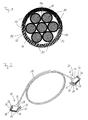
- Fig. 1 shows a cross-sectional view of an electrical line according to the invention with seven conductors 10 made of, for example, copper, which are each surrounded by an insulating lacquer layer 14. Characterized in that the conductors 10 are electrically isolated from each other by their insulating coating layer 14, seven separate signal paths are provided by the illustrated line, which make it possible to transmit a maximum of seven different electrical signals simultaneously. It should be noted that the number of seven conductors here is purely exemplary and may vary depending on the application. This means that lines with more or less than seven conductors are also conceivable.
- the conductors 10 have substantially similar cross-sectional areas, which may range from a few hundredths of a square millimeter to a few tenths of a square millimeter.
- the conductors 10 are twisted together and surrounded by a common conductor sheath 16 having an extruded plastic material.
- Fig. 2 shows an embodiment of an electrical line arrangement according to the invention.
- An electrical line 18 with a as in Fig. 1 shown cross section is connected at both ends with a connector 20.
- the respective end of the electrical line 18 is for this purpose inserted into an opening 22 of the housing 24 of the connector 20.
- the connectors 20 each have one in the housing 24 used insert 26, which with connection elements 36 (FIG. Fig. 3 ) is provided.
- Each conductor 10 of the electrical line is connected by means of a solder connection to one of the connecting elements 36.
- the insert 26 has a plurality of openings 28 through which the connection elements 36 of the connector 20 for complementary connections of a plug connector 20 to the complementary formed socket (not shown) are accessible.
- the housing 24 of the connector 20 has two spring elements 30, each with a locking lug 32, which enter a latching connection with corresponding recesses of the socket when inserting the connector 20 into the socket.
- a key projection 34 is provided on the housing 24, which together with a complementary to the key projection 34 recess of the socket allows insertion of the connector 20 only in a predetermined orientation.
- Fig. 3a-d is a part of the electrical line arrangement according to the invention
- Fig. 2 shown with a portion of the electrical line 18 and the associated connector 20 in different manufacturing states.
- Fig. 3a shows the electrical lead 18 and the housing 24, the insert 26 and the connection elements 36 of the connector 20 prior to assembly of the connector 20 and establishing the connection between the connector 20 and the electrical line 18th
- connection element 36 has a soldering surface 44, to which a conductor 10 is soldered and the conductor 10 can thereby be connected to the connection element 36.
- the conductor 10 can also by means of a Crimpthetic or in other material and / or non-positive manner to the connection elements 36 are connected.
- the insert 26 of the connector 20 has a plurality of slots 42, in each of which a connection element 36 can be inserted.
- the cable jacket 16 of the line 18 is removed in a region of the illustrated end of the line 18, so that the individual conductors 10 twisted together are freely accessible.
- the insert 26 has a latching nose 38, which engages in the inserted state in a recess 40 of the housing 24 and produces a latching connection between the insert 26 and the housing 24.
- Fig. 3b shows the conduit arrangement after the conduit 18 has been inserted through the opening 22 in the housing 24.
- Fig. 3c shows the line arrangement after the connection elements 36 have been inserted into the corresponding slots 42 of the insert 26 and the conductors 10 have been soldered to the solder pads 42 of the connection elements 36.
- the conductors 10 are stripped for this purpose in the area in which they rest against the solder surfaces 44.
- connection elements 36 are electrically isolated from each other, and all conductors 10 are connected to different connection elements 36. In this way, each conductor 10 provides its own signal path.
- Fig. 3d shows the line arrangement at finished connection between connector 20 and electrical line 18, so after inserting the insert 26 into the housing 24th
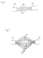
- Fig. 4 shows a central region of an electrical line according to the invention, which has a as in Fig. 1 has shown cross-section. In the illustrated central region of the cable jacket 16 is partially removed, so that the lacquer-insulated conductor 10 are accessible from the outside.
- Fig. 5 shows the central region of the electrical line according to the invention of Fig. 4 , wherein the enamel-insulated conductor 10 in the region in which the cable jacket 10 has been removed, spaced from each other and thus are individually accessible.
- this spaced apart arrangement can be created simply by twisting the two ends of the central region against the direction of rotation of the twisted conductors 10 and slightly pressing the two ends towards each other.
Landscapes
- Insulated Conductors (AREA)
- Communication Cables (AREA)
Abstract
Description
- Die vorliegende Erfindung betrifft eine elektrische Leitung und eine elektrische Leitungsanordnung, die wenigstens eine elektrische Leitung umfasst, beides insbesondere zur gleichzeitigen Übertragung von mehreren verschiedenen Steuersignalen in einem Kraftfahrzeug.
- Die zunehmende Bedeutung elektronischer Funktionen in modernen Systemen, insbesondere in Kraftfahrzeugen, macht eine gleichzeitige Übertragung einer Vielzahl unterschiedlicher Signale in diesen Systemen notwendig. Eine solche gleichzeitige Übertragung mehrerer Signale erfordert eine entsprechende Vielzahl von getrennten elektrischen Signalpfaden, zum Beispiel durch elektrische Leitungen.
- Herkömmliche elektrische Leitungen, insbesondere solche, die für die Übertragung von Steuerungssignalen in einem Kraftfahrzeug ausgelegt sind, bestehen typischerweise aus einem Kupferleiter, welcher von einem isolierenden Leitungsmantel umgeben ist.
- Zur gleichzeitigen Übertragung unterschiedlicher Signale ist es notwendig, eine entsprechende Anzahl solcher Leitungen bereitzustellen, was einen erheblichen Material- und Kostenaufwand sowie Platzbedarf mit sich bringt.
- Eine Aufgabe der Erfindung ist es, eine elektrische Leitung bereitzustellen, in der mehrere verschiedene elektrische Signale gleichzeitig übertragen werden können, die sich durch einen verringerten Materialaufwand und Platzbedarf auszeichnet und die kostengünstig herstellbar ist.
- Zur Lösung der Aufgabe ist eine elektrische Leitung mit den Merkmalen des Anspruchs 1 vorgesehen.
- Die erfindungsgemäße elektrische Leitung umfasst mehrere, von einem gemeinsamen Leitungsmantel umgebene Leiter, die zur Vermeidung von Wechselwirkungen zwischen in den Leitern geführten Signalen jeweils von einer isolierenden Lackschicht umgeben sind.
- Der Erfindung liegt mit anderen Worten der allgemeine Gedanke zugrunde, mehrere einzelne Leiter zu einer Leitung zusammenzufassen und die einzelnen Leiter dabei durch jeweilige Lackschichten gegeneinander zu isolieren, damit unterschiedliche elektrische Signale gleichzeitig und unabhängig voneinander über die Leitung übertragen werden können. Die besonderen Vorteile der erfindungsgemäßen Leitung liegen in einer besonders kompakten Bauform, einem minimalen Materialaufwand und einer besonders kostengünstigen Herstellbarkeit.
- Die kompakte Bauform wird unter anderem dadurch ermöglicht, dass die isolierende Lackschicht eines Leiters im Vergleich zu dem Querschnitt des Leiters sehr dünn sein kann. Der Materialaufwand und Platzbedarf der erfindungsgemäßen elektrischen Leitung ist dadurch gegenüber einer entsprechenden Mehrzahl von herkömmlichen Einzelsignalleitungen mit jeweils einem eigenen Leitungsmantel stark verringert.
- Außerdem kann die erfindungsgemäße elektrische Leitung aufgrund ihres einfachen Aufbaus auf sehr einfache Weise und somit kostengünstig hergestellt werden. Insbesondere lassen sich hierfür bestehende Werkzeugmaschinen verwenden.
- Bevorzugt handelt es sich bei der erfindungsgemäßen Leitung um eine Fahrzeugleitung des Typs FLY, welche insbesondere eine der Normen DIN EN 13602, DIN 53505 und DIN ISO 6722 Klasse B erfüllt.
- Wenigstens einer der Leiter kann aus einem Metall wie Kupfer oder Aluminium gebildet sein.
- Der gemeinsame Leitungsmantel, in dem die Leiter zusammengefasst und vorzugsweise festgelegt sind, kann in an sich bekannter Weise zumindest im Wesentlichen schlauchförmig oder zylinderförmig ausgestaltet sein und die Leiter von der Umgebung isolieren. Bevorzugt umfasst der Leitungsmantel ein Kunststoffmaterial, welches durch Extrusion hergestellt ist. Besonders bevorzugt ist es, wenn der Leitungsmantel zumindest ein Material aufweist, das aus der Gruppe gewählt ist, die Polyvinylchlorid (PVC), Polyethylen (PE), Polyphenylenether (PPE), Polyurethan und Teflon umfasst.
- Die Anzahl der lackisolierten Leiter innerhalb einer Leitung und damit die Anzahl der gleichzeitig durch die Leitung übertragbaren Signale ist prinzipiell nicht beschränkt. Es ist deshalb problemlos möglich, erfindungsgemäße Leitungen mit unterschiedlichen Anzahlen von lackisolierten Leitern herzustellen und dann in einem konkreten System die notwendigen Signalpfade durch eine entsprechende individuelle Zusammenstellung von mehreren erfindungsgemäßen Leitungen mit entsprechenden und gegebenenfalls verschiedenen Anzahlen von lackisolierten Leitern zu schaffen. Die erfindungsgemäßen Leitungen können dabei in an sich bekannter Weise zu einem Kabelsatz oder Kabelbaum zusammengefasst werden. Die Erfindung eignet sich somit für die Verwendung in einem modularen Leitungssystem und ermöglicht es, mit verringertem Aufwand individuelle Kabelsätze bzw. Kabelbäume mit einem Minimum an ungenutzten Leitern für individuelle Systeme bereitzustellen.
- Vorteilhafte Ausführungsformen der Erfindung sind in der Beschreibung, den Unteransprüchen und den Zeichnungen beschrieben.
- Nach einer vorteilhaften Ausführungsform sind wenigstens zwei der Leiter miteinander verdrillt. Eine solche Verdrillung dient der Unterdrückung von elektromagnetischen Wechselwirkungen zwischen in den verdrillten Leitern geführten Signalen und erhöht die Robustheit der Signalübertragung gegen externe elektromagnetische Störungen. Außerdem wird eine verbesserte mechanische Flexibilität und Bruchsicherheit der elektrischen Leitung gewährleistet.
- Je nach Art der zu übertragenden Signale und möglicher externer Störungen sowie gewünschter mechanischer Eigenschaften der elektrischen Leitung können prinzipiell beliebige Verdrillungen zwischen den Leitern der elektrischen Leitung vorgesehen sein. So können mehrere Leiterpaare paarweise verdrillt sein und/oder die Schlaglängen mehrerer Verdrillungen verschieden sein. Es kann ferner wenigstens eine Verdrillung zweiter Ordnung vorgesehen sein, d.h. eine aus mehreren miteinander verdrillten Leitern bestehende Verdrillung ist mit zumindest einer weiteren Verdrillung von Leitern wiederum verdrillt. Dabei können die die Verdrillung zweiter Ordnung bildenden Verdrillungen prinzipiell identische oder unterschiedliche Schlaglängen aufweisen. Es können auch alle Leiter der elektrischen Leitung in erster Ordnung miteinander verdrillt sein. Grundsätzlich können alle Leiter der elektrischen Leitung im Wesentliche gleiche Querschnittsflächen aufweisen. Alternativ können aber auch zumindest zwei der Leiter unterschiedliche Querschnittsflächen aufweisen. Durch unterschiedliche Querschnittsflächen können unterschiedliche Widerstände der entsprechenden Leiter realisiert werden, was in Abhängigkeit von den jeweils zu übertragenden Signalen und insbesondere deren Frequenzen zweckmäßig sein kann. Je nach Anwendung kann es auch vorteilhaft sein, wenn unterschiedliche Leiter entweder unterschiedliche Querschnittsflächen und/oder unterschiedliche Dicken der isolierenden Lackschicht aufweisen.
- Gemäß einer weiteren vorteilhaften Ausführungsform weist wenigstens ein und insbesondere jeder Leiter eine über seine Länge zumindest im Wesentlichen konstante Querschnittsfläche auf, die zum Beispiel im Bereich von einigen Hundertstelquadratmillimetern bis einigen Zehntelquadratmillimetern liegen kann. Ein Leiter mit einer solchen Querschnittsfläche weist für die in automobilen Steuerungsanwendungen gebräuchlichen Signale und Leitungslängen besonders geeignete Übertragungseigenschaften auf. Der Leitungsmantel weist bevorzugt eine über die Länge des Leiters im Wesentlichen konstante Wandstärke im Bereich von einigen Zehntelmillimetern auf, z.B. im Bereich zwischen 0,3 und 0,5 Millimetern.
- Besonders bevorzugt ist es, wenn wenigstens zwei Leiter und insbesondere alle Leiter optisch und/oder haptisch unterscheidbar sind. Dies erleichtert ein korrektes Anschließen unterschiedlicher Signalquellen und -senken an die Leiter.
- Zur Gewährleistung einer optischen Unterscheidbarkeit der Leiter können die Leiter unterschiedlich farbige isolierende Lackschichten aufweisen. Im Fall einer transparenten isolierenden Lackschicht können aber auch die Leiter selbst unterschiedliche Farben aufweisen, zum Beispiel wenn die Leiter aus unterschiedlichen Materialien bestehen. Alternativ oder zusätzlich können die Leiter durch spezielle Oberflächenbeschaffenheiten oder Texturen haptisch unterscheidbar sein.
- Gemäß einer weiteren Ausführungsform ist eine Zugentlastung vorgesehen, welche zum Beispiel durch einen sich über die Länge der elektrischen Leitung erstreckenden Faden und/oder durch eine sich über die Länge der elektrischen Leitung erstreckende Glasfaser gebildet sein kann. Eine solche Zugentlastung verläuft vorzugsweise in der Mitte der Leiter. Im Falle einer Verdrillung von Leitern ist es vorteilhaft, wenn die Leiter um die Zugentlastung herum verdrillt sind. Alternativ kann die Zugentlastung Teil einer Verdrillung sein, also mit wenigstens einem Leiter verdrillt sein.
- Bevorzugt ist es ferner, wenn eine die Leiter umgebende elektrische Abschirmung vorgesehen ist. Eine solche elektrische Abschirmung kann beispielsweise aus einer zwischen den Leitern und dem Leitungsmantel angeordneten elektrisch leitfähigen Folie bestehen.
- Weiterer Gegenstand der Erfindung ist außerdem eine elektrische Leitungsanordnung mit den Merkmalen des Anspruchs 10.
- In der erfindungsgemäßen elektrischen Leitungsanordnung ist wenigstens eine wie vorstehend beschriebene elektrische Leitung mit wenigstens einem elektrischen Verbinder verbunden. Ein solcher Verbinder erlaubt ein vereinfachtes Anschließen der elektrischen Leitungsanordnung an ein Gerät, das einen entsprechenden Gegenverbinder aufweist. Auf diese Weise lassen sich auf besonders einfache Weise mehrere getrennte Signalpfade zwischen Geräten oder dergleichen herstellen.
- Der elektrische Verbinder ist vorteilhafterweise ein Steckverbinder.
- Prinzipiell kann die erfindungsgemäße elektrische Leitungsanordnung eine beliebige Anzahl von elektrischen Leitungen und von mit den elektrischen Leitungen verbundenen Verbindern aufweisen. Je nach Anwendung kann es hierbei vorteilhaft sein, wenn alle Leiter einer elektrischen Leitung jeweils an ihrem einen Ende an einen ersten Verbinder angeschlossen sind und an ihrem anderen Ende mit einem zweiten Verbinder verbunden sind. Bei einer Leitungsanordnung mit mehreren elektrischen Leitungen kann es gegebenenfalls vorteilhaft sein, wenn mehrere elektrische Leitungen mit ein und demselben Verbinder verbunden sind. Umgekehrt können grundsätzlich auch die Leiter ein und derselben elektrischen Leitung an einem Ende der Leitung an unterschiedliche Verbinder angeschlossen sein.
- Sind mehrere Leiter einer elektrischen Leitung oder unterschiedlicher elektrischer Leitungen mit ein und demselben Verbinder verbunden, können wenigstens zwei Leiter zur Bildung unterschiedlicher Signalpfade an verschiedene Anschlusselemente des Verbinders angeschlossen sein. Wenn ein Signalpfad mit einer erhöhten Leitfähigkeit benötigt wird, können aber auch zwei oder mehr Leiter an demselben Anschlusselement eines Verbinders angeschlossen werden. Auf diese Weise kann ein Signal über mehrere Leiter parallel übertragen werden.
- Ein Leiter kann in an sich bekannter Weise und insbesondere durch eine Steck- , Klemm-, Löt-, Press- oder Nietverbindung oder durch eine andere lösbare oder nicht lösbare elektrische Verbindung an ein Anschlusselement eines Verbinders angeschlossen sein.
- Nach einer weiteren vorteilhaften Ausführungsform ist ein an ein Anschlusselement eines Verbinders angeschlossener Leiter einer elektrischen Leitung im Wesentlichen nur in einem Anschlussbereich abisoliert, in welchem der Leiter mit dem Anschlusselement elektrisch in Kontakt steht, d.h. der Leiter weist nur in diesem Bereich keine isolierende Lackschicht auf. Dadurch wird ein Kurzschluss zwischen dem Leiter und anderen leitenden Elementen der Umgebung sowie benachbarten Leitern oder Anschlusselementen verhindert.
- Ein solcher Anschlussbereich liegt üblicherweise im Bereich eines Endes des Leiters. Im Rahmen der Erfindung kann ein Anschlussbereich eines Leiters aber auch in einem zu den Enden des Leiters signifikant beabstandeten, zum Beispiel um mehrere 10 cm beabstandeten, Bereich des Leiters liegen, vorausgesetzt der Leitungsmantel der Leitung ist in diesem Bereich entfernt. Auf diese Weise kann ein Leiter nicht nur an seinen Enden sondern zusätzlich auch in einem mittleren Bereich an ein Anschlusselement eines Verbinders angeschlossen werden.
- Nachfolgend wird die vorliegende Erfindung rein beispielhaft anhand einer vorteilhaften Ausführungsform unter Bezugnahme auf die beigefügten Zeichnungen beschrieben. Es zeigen:
- Fig. 1
- eine Querschnittsansicht einer erfindungsgemäßen elektri- schen Leitung;
- Fig. 2
- eine erfindungsgemäße elektrische Leitungsanordnung;
- Fig. 3a-d
- einen Teil der Leitungsanordnung von
Fig. 2 in unterschiedli- chen Fertigungszuständen; - Fig. 4
- einen Mittelbereich einer erfindungsgemäßen elektrischen Leitung mit einem teilweise entfernten Leitungsmantel; und
- Fig. 5
- den Mittelbereich der erfindungsgemäßen elektrischen Leitung aus
Fig. 4 mit einem teilweise entfernten Leitungsmantel und voneinander beabstandeten Leitern. -
Fig. 1 zeigt eine Querschnittsansicht einer erfindungsgemäßen elektrischen Leitung mit sieben Leitern 10 aus zum Beispiel Kupfer, die jeweils von einer isolierenden Lackschicht 14 umgeben sind. Dadurch, dass die Leiter 10 durch ihre isolierende Lackschicht 14 gegeneinander elektrisch isoliert sind, werden durch die dargestellte Leitung sieben getrennte Signalpfade bereitgestellt, die es ermöglichen, gleichzeitig maximal sieben unterschiedliche elektrische Signale zu übertragen. Es wird darauf hingewiesen, dass die Anzahl von hier sieben Leitern rein beispielhaft gewählt ist und je nach Anwendung hiervon abweichen kann. D.h. es sind auch Leitungen mit mehr oder weniger als sieben Leitern denkbar. - Die Leiter 10 weisen im Wesentlichen gleiche Querschnittsflächen auf, die im Bereich von einigen Hundertstelquadratmillimetern bis einigen Zehntelquadratmillimetern liegen können. Die Leiter 10 sind miteinander verdrillt und von einem gemeinsamen Leitungsmantel 16 umgeben, der ein extrudiertes Kunststoffmaterial aufweist.
-
Fig. 2 zeigt eine Ausführungsform einer erfindungsgemäßen elektrischen Leitungsanordnung. Eine elektrische Leitung 18 mit einem wie inFig. 1 gezeigten Querschnitt ist an beiden Enden jeweils mit einem Steckverbinder 20 verbunden. Das jeweilige Ende der elektrischen Leitung 18 ist hierzu in eine Öffnung 22 des Gehäuses 24 des Steckverbinders 20 eingeführt. Die Steckverbinder 20 verfügen jeweils über einen in das Gehäuse 24 eingesetzten Einsatz 26, der mit Anschlusselementen 36 (Fig. 3 ) versehen ist. Jeder Leiter 10 der elektrischen Leitung ist mittels einer Lötverbindung an eines der Anschlusselemente 36 angeschlossen. Der Einsatz 26 verfügt über mehrere Öffnungen 28, durch die die Anschlusselemente 36 des Steckverbinders 20 für komplementäre Anschlüsse einer zu dem Steckverbinder 20 komplementär ausgebildeten Steckerbuchse (nicht dargestellt) zugänglich sind. - Das Gehäuse 24 des Steckverbinders 20 weist zwei Federelemente 30 mit jeweils einer Rastnase 32 auf, die beim Einstecken des Steckverbinders 20 in die Steckerbuchse eine Rastverbindung mit entsprechenden Ausnehmungen der Steckerbuchse eingehen. Außerdem ist an dem Gehäuse 24 ein Schlüsselvorsprung 34 vorgesehen, der zusammen mit einer zu dem Schlüsselvorsprung 34 komplementären Ausnehmung der Steckerbuchse ein Einstecken des Steckverbinders 20 nur in einer vorgegebenen Orientierung erlaubt.
- In
Fig. 3a-d ist ein Teil der erfindungsgemäßen elektrischen Leitungsanordnung vonFig. 2 mit einem Teil der elektrischen Leitung 18 und dem zugeordneten Steckverbinder 20 in unterschiedlichen Fertigungszuständen dargestellt. -
Fig. 3a zeigt die elektrische Leitung 18 sowie das Gehäuse 24, den Einsatz 26 und die Anschlusselemente 36 des Steckverbinders 20 vor dem Zusammensetzen des Steckverbinders 20 und dem Herstellen der Verbindung zwischen dem Steckverbinder 20 und der elektrischen Leitung 18. - Jedes Anschlusselement 36 weist eine Lötfläche 44 auf, an die ein Leiter 10 angelötet und der Leiter 10 dadurch an das Anschlusselement 36 angeschlossen werden kann. Alternativ können die Leiter 10 auch mittels einer Crimpverbindung oder auf andere stoff- und/oder kraftschlüssige Art an die Anschlusselemente 36 angeschlossen werden.
- Der Einsatz 26 des Steckverbinders 20 weist mehrere Steckplätze 42 auf, in die jeweils ein Anschlusselement 36 eingesteckt werden kann.
- Der Leitungsmantel 16 der Leitung 18 ist in einem Bereich des dargestellten Endes der Leitung 18 entfernt, sodass die einzelnen miteinander verdrillten Leiter 10 frei zugänglich sind. Der Einsatz 26 weist eine Rastnase 38 auf, die im eingesetzten Zustand in eine Aussparung 40 des Gehäuses 24 eingreift und eine Rastverbindung zwischen dem Einsatz 26 und dem Gehäuse 24 herstellt.
-
Fig. 3b zeigt die Leitungsanordnung, nachdem die Leitung 18 durch die Öffnung 22 in das Gehäuse 24 eingesetzt wurde. -
Fig. 3c zeigt die Leitungsanordnung, nachdem die Anschlusselemente 36 in die entsprechenden Steckplätze 42 des Einsatzes 26 eingesteckt wurden und die Leiter 10 an die Lötflächen 42 der Anschlusselemente 36 angelötet wurden. Die Leiter 10 sind zu diesem Zweck in dem Bereich abisoliert, in welchem sie an den Lötflächen 44 anliegen. - Die eingesteckten Anschlusselemente 36 sind elektrisch voneinander isoliert, und alle Leiter 10 sind an unterschiedliche Anschlusselemente 36 angeschlossen. Auf diese Weise stellt jeder Leiter 10 einen eigenen Signalpfad bereit.
-
Fig. 3d zeigt die Leitungsanordnung bei fertiger Verbindung zwischen Steckverbinder 20 und elektrischer Leitung 18, also nach dem Einsetzen des Einsatzes 26 in das Gehäuse 24. -
Fig. 4 zeigt einen Mittelbereich einer erfindungsgemäßen elektrischen Leitung, die einen wie inFig. 1 dargestellten Querschnitt aufweist. In dem dargestellten Mittelbereich ist der Leitungsmantel 16 teilweise entfernt, sodass die lackisolierten Leiter 10 von außen zugänglich sind. -
Fig. 5 zeigt den Mittelbereich der erfindungsgemäßen elektrischen Leitung vonFig. 4 , wobei die lackisolierten Leiter 10 in dem Bereich, in dem der Leitungsmantel 10 entfernt wurde, voneinander beabstandet und somit einzeln zugänglich sind. Diese beabstandete Anordnung kann zum Beispiel einfach dadurch erzeugt werden, dass die beiden Enden des Mittelbereichs entgegen der Drehrichtung der verdrillten Leiter 10 etwas verdreht werden und die beiden Enden leicht aufeinander zu gedrückt werden. - In der in
Fig. 5 dargestellten Situation ist es möglich, die einzelnen Leiter 10 in dem dargestellten Mittelbereich durch örtliches Abisolieren der Leiter 10 und Verbinden mit entsprechenden Verbindern zu kontaktieren, wodurch zusätzliche Anschlussmöglichkeiten in dem Mittelbereich der elektrischen Leitung geschaffen werden. -
- 10
- Leiter
- 14
- isolierende Lackschicht
- 16
- Leitungsmantel
- 18
- elektrische Leitung
- 20
- Steckverbinder
- 22
- Öffnung
- 24
- Gehäuse
- 26
- Einsatz
- 28
- Öffnung
- 30
- Federelement
- 32
- Rastnase
- 34
- Schlüsselvorsprung
- 36
- Anschlusselement
- 38
- Rastnase
- 40
- Aussparung
- 42
- Steckplatz
- 44
- Lötfläche
Claims (15)
- Elektrische Leitung mit mehreren von einem gemeinsamen Leitungsmantel (16) umgebenen Leitern (10), die zur Vermeidung von Wechselwirkungen zwischen unterschiedlichen in den Leitern (10) geführten Signalen jeweils von einer isolierenden Lackschicht (14) umgeben sind.
- Elektrische Leitung nach Anspruch 1,
dadurch gekennzeichnet, dass
wenigstens zwei der Leiter (10) miteinander verdrillt sind. - Elektrische Leitung nach Anspruch 1 oder 2,
dadurch gekennzeichnet, dass
die Leiter (10) alle im Wesentlichen gleiche Querschnittsflächen aufweisen oder zumindest zwei der Leiter (10) unterschiedliche Querschnittsflächen aufweisen. - Elektrische Leitung nach einem der vorstehenden Ansprüche,
dadurch gekennzeichnet, dass
wenigstens ein und insbesondere jeder Leiter (10) eine über seine jeweilige Länge zumindest im Wesentlichen konstante Querschnittsfläche im Bereich von einigen Hundertstelquadratmillimetern bis einigen Zehntelquadratmillimetern aufweist. - Elektrische Leitung nach einem der vorstehenden Ansprüche,
dadurch gekennzeichnet, dass
wenigstens zwei Leiter (10) und insbesondere alle Leiter optisch und/oder haptisch unterscheidbar sind. - Elektrische Leitung nach einem der vorstehenden Ansprüche,
dadurch gekennzeichnet, dass
der Leitungsmantel (16) ein, insbesondere extrudiertes, Kunststoffmaterial aufweist, welches insbesondere aus der Gruppe gewählt ist, die Polyvinylchlorid, Polyethylen, Polyphenylenether, Polyurethan und Teflon umfasst. - Elektrische Leitung nach einem der vorstehenden Ansprüche,
dadurch gekennzeichnet, dass
eine Zugentlastung vorgesehen ist, welche insbesondere durch einen sich über die gesamte Länge der elektrischen Leitung erstreckenden Faden und/oder durch eine sich über die gesamte Länge der elektrischen Leitung erstreckende Glasfaser gebildet ist. - Elektrische Leitung nach einem der vorstehenden Ansprüche,
dadurch gekennzeichnet, dass
eine die Leiter (10) umgebene elektrische Abschirmung vorgesehen ist. - Verwendung einer elektrischen Leitung nach einem der vorstehenden Ansprüche zur gleichzeitigen Übertragung unterschiedlicher elektrischer Signale.
- Elektrische Leitungsanordnung mit wenigstens einem Verbinder (20) und wenigstens einer elektrischen Leitung (18) nach einem der Ansprüche 1 bis 9, die mit dem wenigstens einen Verbinder (20) verbunden ist, wobei mindestens ein Leiter (10) der elektrischen Leitung (18) an ein Anschlusselement (36) des Verbinders (20) angeschlossen ist.
- Elektrische Leitungsanordnung nach Anspruch 10,
dadurch gekennzeichnet, dass
mindestens zwei Leiter (10) der elektrischen Leitung (18) an verschiedene Anschlusselemente (36) des Verbinders (20) angeschlossen sind. - Elektrische Leitungsanordnung nach Anspruch 10 oder 11,
dadurch gekennzeichnet, dass
mindestens zwei Leiter (10) der elektrischen Leitung (18) an demselben Anschlusselement (36) des Verbinders (20) angeschlossen sind. - Elektrische Leitungsanordnung nach einem der Ansprüche 10 bis 12,
dadurch gekennzeichnet, dass
ein an ein Anschlusselement (36) des Verbinders (20) angeschlossener Leiter (10) im Wesentlichen nur in einem Anschlussbereich abisoliert ist, in welchem der Leiter (10) mit dem Anschlusselement (36) elektrisch in Kontakt steht. - Elektrische Leitungsanordnung nach Anspruch 13,
dadurch gekennzeichnet, dass
der Anschlussbereich im Bereich eines Endes des Leiters (10) liegt. - Elektrische Leitungsanordnung nach Anspruch 13 oder 14, dadurch gekennzeichnet, dass
der Anschlussbereich in einem zu den Enden des Leiters (10) signifikant beabstandeten Bereich des Leiters liegt.
Priority Applications (1)
| Application Number | Priority Date | Filing Date | Title |
|---|---|---|---|
| EP09006183.9A EP2267728B1 (de) | 2009-05-06 | 2009-05-06 | Elektrische Leitung und Leitungsanordnung |
Applications Claiming Priority (1)
| Application Number | Priority Date | Filing Date | Title |
|---|---|---|---|
| EP09006183.9A EP2267728B1 (de) | 2009-05-06 | 2009-05-06 | Elektrische Leitung und Leitungsanordnung |
Publications (2)
| Publication Number | Publication Date |
|---|---|
| EP2267728A1 true EP2267728A1 (de) | 2010-12-29 |
| EP2267728B1 EP2267728B1 (de) | 2018-07-11 |
Family
ID=40912098
Family Applications (1)
| Application Number | Title | Priority Date | Filing Date |
|---|---|---|---|
| EP09006183.9A Not-in-force EP2267728B1 (de) | 2009-05-06 | 2009-05-06 | Elektrische Leitung und Leitungsanordnung |
Country Status (1)
| Country | Link |
|---|---|
| EP (1) | EP2267728B1 (de) |
Citations (5)
| Publication number | Priority date | Publication date | Assignee | Title |
|---|---|---|---|---|
| US3676576A (en) * | 1969-07-07 | 1972-07-11 | Aerospatiale | Multiconductor stranded remote-control cable |
| DE2210222A1 (de) * | 1971-03-06 | 1973-02-15 | Daito Special Electrical Wire | Elektrische leitung |
| DE2803007B1 (de) * | 1978-01-20 | 1979-02-15 | Siemens Ag | Zweiadrige elektrische Leitung |
| US4715119A (en) * | 1985-04-11 | 1987-12-29 | U.S. Philips Corporation | Method of manufacturing a plug |
| DE102005062714A1 (de) * | 2005-12-28 | 2007-07-05 | Aiv Kabelwerk Gmbh | Kabel |
Family Cites Families (3)
| Publication number | Priority date | Publication date | Assignee | Title |
|---|---|---|---|---|
| JP2000268641A (ja) * | 1999-03-16 | 2000-09-29 | Sumitomo Wiring Syst Ltd | ワイヤハーネス用電線 |
| US6713737B1 (en) * | 2001-11-26 | 2004-03-30 | Illinois Tool Works Inc. | System for reducing noise from a thermocouple in an induction heating system |
| DE20201726U1 (de) * | 2002-02-05 | 2002-04-11 | Hsing Chau Industrial Co., Ltd., Taipeh/T'ai-Pei | Anschlußadapter für Videographik-Beschleunigerkarten |
-
2009
- 2009-05-06 EP EP09006183.9A patent/EP2267728B1/de not_active Not-in-force
Patent Citations (5)
| Publication number | Priority date | Publication date | Assignee | Title |
|---|---|---|---|---|
| US3676576A (en) * | 1969-07-07 | 1972-07-11 | Aerospatiale | Multiconductor stranded remote-control cable |
| DE2210222A1 (de) * | 1971-03-06 | 1973-02-15 | Daito Special Electrical Wire | Elektrische leitung |
| DE2803007B1 (de) * | 1978-01-20 | 1979-02-15 | Siemens Ag | Zweiadrige elektrische Leitung |
| US4715119A (en) * | 1985-04-11 | 1987-12-29 | U.S. Philips Corporation | Method of manufacturing a plug |
| DE102005062714A1 (de) * | 2005-12-28 | 2007-07-05 | Aiv Kabelwerk Gmbh | Kabel |
Also Published As
| Publication number | Publication date |
|---|---|
| EP2267728B1 (de) | 2018-07-11 |
Similar Documents
| Publication | Publication Date | Title |
|---|---|---|
| DE102017219214B4 (de) | Verzweigungsaufbau und kabelbaum | |
| EP2883287B1 (de) | System aus einem steckverbinder und kontaktelementen | |
| EP3020098B1 (de) | Mehrfachsteckverbinder | |
| DE112015005676B4 (de) | Verbinder und Elektrokabeleinheit | |
| DE112012003925T5 (de) | Kabelstrang | |
| EP4503344B1 (de) | Konfektioniertes elektrisches kabel und steckverbinderanordnung | |
| DE69512162T2 (de) | Flachkabel mit an Verbinder anschliessbaren Leiterenden | |
| EP3671975B1 (de) | Kabelsteckverbinderanordnung, kabelsteckverbinder und pressmittel | |
| EP3714513A1 (de) | Elektrischer verbinder und damit ausgestattete elektrische leitungsanordnung | |
| EP3323176B1 (de) | Steckverbindungsanordnung mit kodierung | |
| DE4412968C2 (de) | Elektrischer Verbindungskasten | |
| DE102015122868A1 (de) | Mehrfachstecker insbesondere für ein Fahrzeug zum Anschließen eines Koaxialkabels, mit dem Mehrfachstecker verbindbare Buchse, Mehrfachsteckverbindung umfassend einen derartigen Mehrfachstecker und eine derartige Buchse sowie Fahrzeug mit einem solchen Mehrfachstecker | |
| DE102020124893A1 (de) | Steckverbinder und verfahren | |
| DE102010022466A1 (de) | Elektrischer Verbinder | |
| EP2051341A2 (de) | Kabeleinrichtung mit geschirmten Kabelstücken | |
| DE102013009330A1 (de) | Kontaktträger mit Kontaktträgerelementen | |
| EP2267728B1 (de) | Elektrische Leitung und Leitungsanordnung | |
| EP3367514A1 (de) | Steckverbindung für hochfrequenzanwendungen, zum beispiel für ethernet anwendung | |
| DE102011004873B4 (de) | Flachbandkabelmantel für AS-Interface Systeme | |
| WO2020048890A1 (de) | Elektrische verteilervorrichtung, montageverfahren und signalübertragungssystem | |
| DE102016206961B4 (de) | Multifunktionskabel | |
| EP2786450B1 (de) | Isolierkörper eines steckverbinders | |
| DE202018100521U1 (de) | Elektrische Verbindungseinrichtung | |
| DE102023001729B4 (de) | Steckverbinder | |
| EP0908970A1 (de) | Hybrides HF-Steckverbindungssystem |
Legal Events
| Date | Code | Title | Description |
|---|---|---|---|
| PUAI | Public reference made under article 153(3) epc to a published international application that has entered the european phase |
Free format text: ORIGINAL CODE: 0009012 |
|
| 17P | Request for examination filed |
Effective date: 20100430 |
|
| AK | Designated contracting states |
Kind code of ref document: A1 Designated state(s): AT BE BG CH CY CZ DE DK EE ES FI FR GB GR HR HU IE IS IT LI LT LU LV MC MK MT NL NO PL PT RO SE SI SK TR |
|
| AX | Request for extension of the european patent |
Extension state: AL BA RS |
|
| STAA | Information on the status of an ep patent application or granted ep patent |
Free format text: STATUS: EXAMINATION IS IN PROGRESS |
|
| 17Q | First examination report despatched |
Effective date: 20161223 |
|
| GRAP | Despatch of communication of intention to grant a patent |
Free format text: ORIGINAL CODE: EPIDOSNIGR1 |
|
| STAA | Information on the status of an ep patent application or granted ep patent |
Free format text: STATUS: GRANT OF PATENT IS INTENDED |
|
| INTG | Intention to grant announced |
Effective date: 20171204 |
|
| GRAS | Grant fee paid |
Free format text: ORIGINAL CODE: EPIDOSNIGR3 |
|
| GRAA | (expected) grant |
Free format text: ORIGINAL CODE: 0009210 |
|
| STAA | Information on the status of an ep patent application or granted ep patent |
Free format text: STATUS: THE PATENT HAS BEEN GRANTED |
|
| AK | Designated contracting states |
Kind code of ref document: B1 Designated state(s): AT BE BG CH CY CZ DE DK EE ES FI FR GB GR HR HU IE IS IT LI LT LU LV MC MK MT NL NO PL PT RO SE SI SK TR |
|
| REG | Reference to a national code |
Ref country code: GB Ref legal event code: FG4D Free format text: NOT ENGLISH |
|
| REG | Reference to a national code |
Ref country code: CH Ref legal event code: EP |
|
| REG | Reference to a national code |
Ref country code: AT Ref legal event code: REF Ref document number: 1017767 Country of ref document: AT Kind code of ref document: T Effective date: 20180715 |
|
| REG | Reference to a national code |
Ref country code: IE Ref legal event code: FG4D Free format text: LANGUAGE OF EP DOCUMENT: GERMAN |
|
| REG | Reference to a national code |
Ref country code: DE Ref legal event code: R096 Ref document number: 502009015073 Country of ref document: DE |
|
| REG | Reference to a national code |
Ref country code: NL Ref legal event code: MP Effective date: 20180711 |
|
| REG | Reference to a national code |
Ref country code: LT Ref legal event code: MG4D |
|
| REG | Reference to a national code |
Ref country code: DE Ref legal event code: R081 Ref document number: 502009015073 Country of ref document: DE Owner name: APTIV TECHNOLOGIES LIMITED, BB Free format text: FORMER OWNER: DELPHI TECHNOLOGIES, INC., TROY, MICH., US |
|
| PG25 | Lapsed in a contracting state [announced via postgrant information from national office to epo] |
Ref country code: NL Free format text: LAPSE BECAUSE OF FAILURE TO SUBMIT A TRANSLATION OF THE DESCRIPTION OR TO PAY THE FEE WITHIN THE PRESCRIBED TIME-LIMIT Effective date: 20180711 |
|
| PG25 | Lapsed in a contracting state [announced via postgrant information from national office to epo] |
Ref country code: FI Free format text: LAPSE BECAUSE OF FAILURE TO SUBMIT A TRANSLATION OF THE DESCRIPTION OR TO PAY THE FEE WITHIN THE PRESCRIBED TIME-LIMIT Effective date: 20180711 Ref country code: BG Free format text: LAPSE BECAUSE OF FAILURE TO SUBMIT A TRANSLATION OF THE DESCRIPTION OR TO PAY THE FEE WITHIN THE PRESCRIBED TIME-LIMIT Effective date: 20181011 Ref country code: SE Free format text: LAPSE BECAUSE OF FAILURE TO SUBMIT A TRANSLATION OF THE DESCRIPTION OR TO PAY THE FEE WITHIN THE PRESCRIBED TIME-LIMIT Effective date: 20180711 Ref country code: GR Free format text: LAPSE BECAUSE OF FAILURE TO SUBMIT A TRANSLATION OF THE DESCRIPTION OR TO PAY THE FEE WITHIN THE PRESCRIBED TIME-LIMIT Effective date: 20181012 Ref country code: IS Free format text: LAPSE BECAUSE OF FAILURE TO SUBMIT A TRANSLATION OF THE DESCRIPTION OR TO PAY THE FEE WITHIN THE PRESCRIBED TIME-LIMIT Effective date: 20181111 Ref country code: NO Free format text: LAPSE BECAUSE OF FAILURE TO SUBMIT A TRANSLATION OF THE DESCRIPTION OR TO PAY THE FEE WITHIN THE PRESCRIBED TIME-LIMIT Effective date: 20181011 Ref country code: PL Free format text: LAPSE BECAUSE OF FAILURE TO SUBMIT A TRANSLATION OF THE DESCRIPTION OR TO PAY THE FEE WITHIN THE PRESCRIBED TIME-LIMIT Effective date: 20180711 Ref country code: LT Free format text: LAPSE BECAUSE OF FAILURE TO SUBMIT A TRANSLATION OF THE DESCRIPTION OR TO PAY THE FEE WITHIN THE PRESCRIBED TIME-LIMIT Effective date: 20180711 |
|
| REG | Reference to a national code |
Ref country code: GB Ref legal event code: 732E Free format text: REGISTERED BETWEEN 20190117 AND 20190123 |
|
| REG | Reference to a national code |
Ref country code: GB Ref legal event code: 732E Free format text: REGISTERED BETWEEN 20190124 AND 20190130 |
|
| PG25 | Lapsed in a contracting state [announced via postgrant information from national office to epo] |
Ref country code: HR Free format text: LAPSE BECAUSE OF FAILURE TO SUBMIT A TRANSLATION OF THE DESCRIPTION OR TO PAY THE FEE WITHIN THE PRESCRIBED TIME-LIMIT Effective date: 20180711 Ref country code: LV Free format text: LAPSE BECAUSE OF FAILURE TO SUBMIT A TRANSLATION OF THE DESCRIPTION OR TO PAY THE FEE WITHIN THE PRESCRIBED TIME-LIMIT Effective date: 20180711 Ref country code: ES Free format text: LAPSE BECAUSE OF FAILURE TO SUBMIT A TRANSLATION OF THE DESCRIPTION OR TO PAY THE FEE WITHIN THE PRESCRIBED TIME-LIMIT Effective date: 20180711 |
|
| REG | Reference to a national code |
Ref country code: DE Ref legal event code: R097 Ref document number: 502009015073 Country of ref document: DE |
|
| PG25 | Lapsed in a contracting state [announced via postgrant information from national office to epo] |
Ref country code: CZ Free format text: LAPSE BECAUSE OF FAILURE TO SUBMIT A TRANSLATION OF THE DESCRIPTION OR TO PAY THE FEE WITHIN THE PRESCRIBED TIME-LIMIT Effective date: 20180711 Ref country code: RO Free format text: LAPSE BECAUSE OF FAILURE TO SUBMIT A TRANSLATION OF THE DESCRIPTION OR TO PAY THE FEE WITHIN THE PRESCRIBED TIME-LIMIT Effective date: 20180711 Ref country code: IT Free format text: LAPSE BECAUSE OF FAILURE TO SUBMIT A TRANSLATION OF THE DESCRIPTION OR TO PAY THE FEE WITHIN THE PRESCRIBED TIME-LIMIT Effective date: 20180711 Ref country code: EE Free format text: LAPSE BECAUSE OF FAILURE TO SUBMIT A TRANSLATION OF THE DESCRIPTION OR TO PAY THE FEE WITHIN THE PRESCRIBED TIME-LIMIT Effective date: 20180711 |
|
| PLBE | No opposition filed within time limit |
Free format text: ORIGINAL CODE: 0009261 |
|
| STAA | Information on the status of an ep patent application or granted ep patent |
Free format text: STATUS: NO OPPOSITION FILED WITHIN TIME LIMIT |
|
| PG25 | Lapsed in a contracting state [announced via postgrant information from national office to epo] |
Ref country code: DK Free format text: LAPSE BECAUSE OF FAILURE TO SUBMIT A TRANSLATION OF THE DESCRIPTION OR TO PAY THE FEE WITHIN THE PRESCRIBED TIME-LIMIT Effective date: 20180711 Ref country code: SK Free format text: LAPSE BECAUSE OF FAILURE TO SUBMIT A TRANSLATION OF THE DESCRIPTION OR TO PAY THE FEE WITHIN THE PRESCRIBED TIME-LIMIT Effective date: 20180711 |
|
| 26N | No opposition filed |
Effective date: 20190412 |
|
| PG25 | Lapsed in a contracting state [announced via postgrant information from national office to epo] |
Ref country code: SI Free format text: LAPSE BECAUSE OF FAILURE TO SUBMIT A TRANSLATION OF THE DESCRIPTION OR TO PAY THE FEE WITHIN THE PRESCRIBED TIME-LIMIT Effective date: 20180711 |
|
| REG | Reference to a national code |
Ref country code: CH Ref legal event code: PL |
|
| PG25 | Lapsed in a contracting state [announced via postgrant information from national office to epo] |
Ref country code: LI Free format text: LAPSE BECAUSE OF NON-PAYMENT OF DUE FEES Effective date: 20190531 Ref country code: CH Free format text: LAPSE BECAUSE OF NON-PAYMENT OF DUE FEES Effective date: 20190531 Ref country code: MC Free format text: LAPSE BECAUSE OF FAILURE TO SUBMIT A TRANSLATION OF THE DESCRIPTION OR TO PAY THE FEE WITHIN THE PRESCRIBED TIME-LIMIT Effective date: 20180711 |
|
| REG | Reference to a national code |
Ref country code: BE Ref legal event code: MM Effective date: 20190531 |
|
| PG25 | Lapsed in a contracting state [announced via postgrant information from national office to epo] |
Ref country code: LU Free format text: LAPSE BECAUSE OF NON-PAYMENT OF DUE FEES Effective date: 20190506 |
|
| PG25 | Lapsed in a contracting state [announced via postgrant information from national office to epo] |
Ref country code: TR Free format text: LAPSE BECAUSE OF FAILURE TO SUBMIT A TRANSLATION OF THE DESCRIPTION OR TO PAY THE FEE WITHIN THE PRESCRIBED TIME-LIMIT Effective date: 20180711 |
|
| PG25 | Lapsed in a contracting state [announced via postgrant information from national office to epo] |
Ref country code: IE Free format text: LAPSE BECAUSE OF NON-PAYMENT OF DUE FEES Effective date: 20190506 |
|
| PG25 | Lapsed in a contracting state [announced via postgrant information from national office to epo] |
Ref country code: BE Free format text: LAPSE BECAUSE OF NON-PAYMENT OF DUE FEES Effective date: 20190531 |
|
| PG25 | Lapsed in a contracting state [announced via postgrant information from national office to epo] |
Ref country code: PT Free format text: LAPSE BECAUSE OF FAILURE TO SUBMIT A TRANSLATION OF THE DESCRIPTION OR TO PAY THE FEE WITHIN THE PRESCRIBED TIME-LIMIT Effective date: 20181111 |
|
| REG | Reference to a national code |
Ref country code: AT Ref legal event code: MM01 Ref document number: 1017767 Country of ref document: AT Kind code of ref document: T Effective date: 20190506 |
|
| PG25 | Lapsed in a contracting state [announced via postgrant information from national office to epo] |
Ref country code: AT Free format text: LAPSE BECAUSE OF NON-PAYMENT OF DUE FEES Effective date: 20190506 |
|
| PG25 | Lapsed in a contracting state [announced via postgrant information from national office to epo] |
Ref country code: CY Free format text: LAPSE BECAUSE OF FAILURE TO SUBMIT A TRANSLATION OF THE DESCRIPTION OR TO PAY THE FEE WITHIN THE PRESCRIBED TIME-LIMIT Effective date: 20180711 |
|
| PG25 | Lapsed in a contracting state [announced via postgrant information from national office to epo] |
Ref country code: HU Free format text: LAPSE BECAUSE OF FAILURE TO SUBMIT A TRANSLATION OF THE DESCRIPTION OR TO PAY THE FEE WITHIN THE PRESCRIBED TIME-LIMIT; INVALID AB INITIO Effective date: 20090506 Ref country code: MT Free format text: LAPSE BECAUSE OF FAILURE TO SUBMIT A TRANSLATION OF THE DESCRIPTION OR TO PAY THE FEE WITHIN THE PRESCRIBED TIME-LIMIT Effective date: 20180711 |
|
| PG25 | Lapsed in a contracting state [announced via postgrant information from national office to epo] |
Ref country code: MK Free format text: LAPSE BECAUSE OF FAILURE TO SUBMIT A TRANSLATION OF THE DESCRIPTION OR TO PAY THE FEE WITHIN THE PRESCRIBED TIME-LIMIT Effective date: 20180711 |
|
| P01 | Opt-out of the competence of the unified patent court (upc) registered |
Effective date: 20230425 |
|
| PGFP | Annual fee paid to national office [announced via postgrant information from national office to epo] |
Ref country code: FR Payment date: 20230525 Year of fee payment: 15 Ref country code: DE Payment date: 20230517 Year of fee payment: 15 |
|
| PGFP | Annual fee paid to national office [announced via postgrant information from national office to epo] |
Ref country code: GB Payment date: 20230518 Year of fee payment: 15 |
|
| REG | Reference to a national code |
Ref country code: DE Ref legal event code: R119 Ref document number: 502009015073 Country of ref document: DE |
|
| GBPC | Gb: european patent ceased through non-payment of renewal fee |
Effective date: 20240506 |
|
| PG25 | Lapsed in a contracting state [announced via postgrant information from national office to epo] |
Ref country code: DE Free format text: LAPSE BECAUSE OF NON-PAYMENT OF DUE FEES Effective date: 20241203 |
|
| PG25 | Lapsed in a contracting state [announced via postgrant information from national office to epo] |
Ref country code: FR Free format text: LAPSE BECAUSE OF NON-PAYMENT OF DUE FEES Effective date: 20240531 |
|
| PG25 | Lapsed in a contracting state [announced via postgrant information from national office to epo] |
Ref country code: GB Free format text: LAPSE BECAUSE OF NON-PAYMENT OF DUE FEES Effective date: 20240506 |