EP2266096B1 - Verfahren und vorrichtung zur verbesserung der wahrnehmungsqualität von farbbildern - Google Patents
Verfahren und vorrichtung zur verbesserung der wahrnehmungsqualität von farbbildern Download PDFInfo
- Publication number
- EP2266096B1 EP2266096B1 EP09719008.6A EP09719008A EP2266096B1 EP 2266096 B1 EP2266096 B1 EP 2266096B1 EP 09719008 A EP09719008 A EP 09719008A EP 2266096 B1 EP2266096 B1 EP 2266096B1
- Authority
- EP
- European Patent Office
- Prior art keywords
- pixel
- interest
- luminance
- value
- chrominance
- Prior art date
- Legal status (The legal status is an assumption and is not a legal conclusion. Google has not performed a legal analysis and makes no representation as to the accuracy of the status listed.)
- Active
Links
- 238000000034 method Methods 0.000 title claims description 24
- 238000012545 processing Methods 0.000 claims description 29
- 239000003623 enhancer Substances 0.000 claims description 25
- 238000009877 rendering Methods 0.000 claims description 9
- 238000001514 detection method Methods 0.000 claims description 5
- 238000004590 computer program Methods 0.000 claims description 3
- 101100327347 Saccharomyces cerevisiae (strain ATCC 204508 / S288c) CDD1 gene Proteins 0.000 claims 1
- 238000004364 calculation method Methods 0.000 claims 1
- 238000012163 sequencing technique Methods 0.000 claims 1
- 230000000007 visual effect Effects 0.000 description 18
- 238000001914 filtration Methods 0.000 description 9
- 238000012937 correction Methods 0.000 description 8
- 238000010586 diagram Methods 0.000 description 8
- 230000003321 amplification Effects 0.000 description 6
- 238000003199 nucleic acid amplification method Methods 0.000 description 6
- 238000000605 extraction Methods 0.000 description 4
- 230000008569 process Effects 0.000 description 4
- 208000019300 CLIPPERS Diseases 0.000 description 3
- 208000021930 chronic lymphocytic inflammation with pontine perivascular enhancement responsive to steroids Diseases 0.000 description 3
- 230000001419 dependent effect Effects 0.000 description 3
- 230000006870 function Effects 0.000 description 3
- 230000004044 response Effects 0.000 description 3
- 238000005070 sampling Methods 0.000 description 3
- 238000004891 communication Methods 0.000 description 2
- 230000006866 deterioration Effects 0.000 description 2
- 238000012986 modification Methods 0.000 description 2
- 230000004048 modification Effects 0.000 description 2
- 230000003287 optical effect Effects 0.000 description 2
- 229920006395 saturated elastomer Polymers 0.000 description 2
- 230000002411 adverse Effects 0.000 description 1
- 238000004458 analytical method Methods 0.000 description 1
- 230000008901 benefit Effects 0.000 description 1
- 230000001413 cellular effect Effects 0.000 description 1
- 238000006243 chemical reaction Methods 0.000 description 1
- 239000003086 colorant Substances 0.000 description 1
- 230000007423 decrease Effects 0.000 description 1
- 230000003247 decreasing effect Effects 0.000 description 1
- 230000000694 effects Effects 0.000 description 1
- 238000002474 experimental method Methods 0.000 description 1
- 239000000284 extract Substances 0.000 description 1
- 230000002349 favourable effect Effects 0.000 description 1
- 239000011159 matrix material Substances 0.000 description 1
- 230000002265 prevention Effects 0.000 description 1
- 238000003672 processing method Methods 0.000 description 1
Images


Classifications
-
- G06T5/73—
-
- H—ELECTRICITY
- H04—ELECTRIC COMMUNICATION TECHNIQUE
- H04N—PICTORIAL COMMUNICATION, e.g. TELEVISION
- H04N9/00—Details of colour television systems
- H04N9/64—Circuits for processing colour signals
- H04N9/68—Circuits for processing colour signals for controlling the amplitude of colour signals, e.g. automatic chroma control circuits
-
- G—PHYSICS
- G06—COMPUTING; CALCULATING OR COUNTING
- G06T—IMAGE DATA PROCESSING OR GENERATION, IN GENERAL
- G06T5/00—Image enhancement or restoration
-
- G—PHYSICS
- G06—COMPUTING; CALCULATING OR COUNTING
- G06T—IMAGE DATA PROCESSING OR GENERATION, IN GENERAL
- G06T5/00—Image enhancement or restoration
- G06T5/20—Image enhancement or restoration by the use of local operators
-
- H—ELECTRICITY
- H04—ELECTRIC COMMUNICATION TECHNIQUE
- H04N—PICTORIAL COMMUNICATION, e.g. TELEVISION
- H04N1/00—Scanning, transmission or reproduction of documents or the like, e.g. facsimile transmission; Details thereof
- H04N1/40—Picture signal circuits
- H04N1/409—Edge or detail enhancement; Noise or error suppression
- H04N1/4092—Edge or detail enhancement
-
- H—ELECTRICITY
- H04—ELECTRIC COMMUNICATION TECHNIQUE
- H04N—PICTORIAL COMMUNICATION, e.g. TELEVISION
- H04N1/00—Scanning, transmission or reproduction of documents or the like, e.g. facsimile transmission; Details thereof
- H04N1/46—Colour picture communication systems
- H04N1/56—Processing of colour picture signals
- H04N1/60—Colour correction or control
- H04N1/6027—Correction or control of colour gradation or colour contrast
-
- H—ELECTRICITY
- H04—ELECTRIC COMMUNICATION TECHNIQUE
- H04N—PICTORIAL COMMUNICATION, e.g. TELEVISION
- H04N5/00—Details of television systems
- H04N5/14—Picture signal circuitry for video frequency region
- H04N5/20—Circuitry for controlling amplitude response
- H04N5/205—Circuitry for controlling amplitude response for correcting amplitude versus frequency characteristic
- H04N5/208—Circuitry for controlling amplitude response for correcting amplitude versus frequency characteristic for compensating for attenuation of high frequency components, e.g. crispening, aperture distortion correction
-
- H—ELECTRICITY
- H04—ELECTRIC COMMUNICATION TECHNIQUE
- H04N—PICTORIAL COMMUNICATION, e.g. TELEVISION
- H04N9/00—Details of colour television systems
- H04N9/64—Circuits for processing colour signals
- H04N9/646—Circuits for processing colour signals for image enhancement, e.g. vertical detail restoration, cross-colour elimination, contour correction, chrominance trapping filters
-
- G—PHYSICS
- G06—COMPUTING; CALCULATING OR COUNTING
- G06T—IMAGE DATA PROCESSING OR GENERATION, IN GENERAL
- G06T2207/00—Indexing scheme for image analysis or image enhancement
- G06T2207/10—Image acquisition modality
- G06T2207/10024—Color image
-
- G—PHYSICS
- G06—COMPUTING; CALCULATING OR COUNTING
- G06T—IMAGE DATA PROCESSING OR GENERATION, IN GENERAL
- G06T2207/00—Indexing scheme for image analysis or image enhancement
- G06T2207/20—Special algorithmic details
- G06T2207/20172—Image enhancement details
- G06T2207/20192—Edge enhancement; Edge preservation
Definitions
- An aspect of the invention relates to a method of image enhancement that can improve perceptual quality of color images.
- Other aspects of the invention relate to an image enhancer, an image rendering system, and a computer program product for a programmable processor.
- Color information is usually represented with a lower resolution than luminance information.
- so-called chromatic sampling may have been applied to a color image in accordance with a particular scheme, such as, for example, a 4:1 :1 or a 4:2:2 sub-sampling scheme.
- a particular scheme such as, for example, a 4:1 :1 or a 4:2:2 sub-sampling scheme.
- Several pixels, which are neighbors of each other, share a same chrominance component, whereas each of these pixels has a unique luminance component. This does generally not affect perceived image quality.
- a typical human observer will generally regard an image where chrominance information has a somewhat lower resolution than luminance information, as being equivalent to a similar image wherein the chrominance information has the same resolution as the luminance information.
- United States patent number 5,982,926 describes that various image enhancement processes have been developed for improving the perceived clarity, intelligibility, and/or quality of images. These image enhancement processes attempt to render images more pleasing to human eyes, irrespective of whether or not these images are accurately reproduced. Oftentimes, a distorted image is more pleasing to the human eye than a perfectly reproduced copy of the original image. For example, if overshoot or undershoot is incorporated into the edges of an image, the resulting image is typically perceived as being more pleasing than an image without such undershoot or overshoot.
- the color image processing device comprises: a color space converter for converting image signals to luminance signals, first chromaticity signals and second chromaticity signals; a luminance signal correcting unit for correcting the luminance signal of a target pixel based on an average luminance signal obtained from the luminance signals of the target pixel and predetermined pixels surrounding the target pixel and the saturation signal of the target pixel; a chromaticity signal correcting unit for correcting the first chromaticity signal and the second chromaticity signal of the target pixel based on the first and second average chromaticity signals obtained from the chromaticity signals of the target pixel and the predetermined pixels surrounding the target pixel, the saturation signal of the target pixel, the average saturation signal obtained from the saturation signals of the target pixel and the predetermined pixels surrounding the target pixel, and a hue difference signal; and a color space inverter for inverting the corrected luminance signals, first chromaticity signals and second chromaticity signals; a luminance signal correcting unit for correcting the luminance signal of
- US2005249430 discloses an image quality improving apparatus and method that distinguish an edge of an actual outline imagely recognized in an image inputted via an image input unit from those printed according to dither patterns, to emphasize the actual outline, and thereby acquire the image without distortion.
- the image quality improving apparatus comprises: a first unit estimating edge pixels of a text area in a predetermined detection area to be edge-detected from an input picture data containing a text and an image; and a second unit judging actual edge pixels based upon a number of edge-estimated pixels in a multiple window area and saturation values of individual edge-estimated pixels, and emphasizing individual actual edge pixels with different edge emphasis coefficients according to saturation values of the actual edge pixels.
- US2002176105 discloses an image processing apparatus which simplifies the circuit arrangement required for edge emphasis correction.
- the apparatus has a first color conversion unit for color-separating input image data into lightness data and chromaticity data, a delay unit for delaying the separated lightness data by N lines, and delaying the chromaticity data by N/2 lines, an image edge amount extraction unit for extracting an image edge portion from the lightness data, a saturation amount extraction unit for extracting the saturation component from the chromaticity data, and an image edge emphasis amount distribution unit for distributing the emphasis amount of the edge portion to an edge emphasis unit so that the distribution ratio for chromaticity correction is higher than that for lightness correction when the saturation component extracted by the saturation extraction unit is large, and the distribution ratio for lightness correction is higher than that for chromaticity correction when the saturation component extracted by the saturation extraction unit is small.
- US2007109423 discloses an image processing apparatus that includes: an image pickup section for converting an object light into image signals of Bayer RGB array; a color information detecting section for obtaining color information of the object from the image signals obtained by the image pickup section; a first luminance data generating section for finding luminance data for use in edge enhancement processing based on G signals of the image signals obtained by the image pickup section; a second luminance data generating section for finding luminance data for use in edge enhancement processing based on all color signals of the image signals; a selector for providing an output by switching between outputs of the first and second luminance data generating section; and a selection signal generating section for generating selection signal for controlling the switching of the selector based on color information obtained at the color information detecting section.
- the image processing apparatus is thereby achieved as capable of edge enhancement processing at favorable S/N and with less occurrence of edge noise in high saturation regions and low saturation regions.
- JPH0382273 proposes a prevention of deterioration in the resolution at a high saturation region at a receiver side by increasing the contour correction in response to the saturation.
- a gain control circuit applies gain control to an inputted contour signal based on a control signal and increases the contour correction quantity more as the control signal is large, that is, the saturation of a chrominance signal is higher to increase the level of the contour signal.
- a contour correction signal subject to gain control by the gain control circuit is fed to an adder circuit, where the signal is added to an original luminance signal and a luminance signal whose edge is emphasized in the picture is extracted in response to the saturation from an output terminal.
- the deterioration in the resolution at a high saturation region at the receiver side is improved to improve the picture quantity.
- a color image is enhanced in the following fashion.
- a saturation detector detects a degree of color saturation that occurs in an image area.
- a filter arrangement filters at least one spatial detail in the image area to a degree that depends on the degree of color saturation.
- spatial details may be emphasized to a relatively high degree in an image area wherein relatively a high degree of color saturation occurs.
- spatial details may be emphasized to a relatively modest degree, or are even left unaltered, in an image area where color saturation is relatively low.
- Such emphasizing of details as a function of color saturation compensates for a seemingly loss of resolution, or a seemingly loss of saturation, or both, in the image area concerned. This allows color images to have a better perceptual quality.
- Various different color images have been enhanced in accordance with the description. Various observers have compared each of these color images with its enhanced version. The enhanced version was clearly perceived as better.
- the filter arrangement preferably amplifies a difference in value between a pixel of interest and neighboring pixels in the image area to a degree that is greater as the degree of color saturation is higher. This allows low-cost implementations.
- the difference in value that is amplified may comprise a luminance value.
- the difference in value that is amplified may comprise a chrominance value.
- the difference in value that is amplified preferably comprises a luminance value and a chrominance value. This contributes to achieving a relatively high perceptual quality.
- the degree to which a difference in chrominance value is amplified is preferably greater than the degree to which a difference in luminance value is amplified. This contributes to achieving a relatively high perceptual quality.
- the degree of color saturation that is detected is preferably that of the pixel of interest. This allows low-cost implementations.
- the saturation detector preferably determines an absolute difference between a chrominance value that belongs to the pixel of interest and a central value, which corresponds with an insignificant degree of saturation.
- a control value may be generated on the basis of the absolute difference, the control value determining the degree to which the difference in value between the pixel of interest and the neighboring pixels is amplified. This allows low- cost implementations.
- the filter arrangement preferably determines a typical value of the neighboring pixels.
- the typical value may than be subtracted from a value that belongs to the pixel of interest, so as to obtain a difference value.
- the difference value is multiplied by a factor that is higher as the degree of color saturation is higher, so as to obtain an amplified difference value.
- the typical value is then added to the amplified difference value, so as to obtain a modified value for the pixel of interest. This allows low-cost implementations.
- a sequencer may successively designate respective pixels in a color image, one by one, as the pixel of interest.
- the aforementioned difference in value is preferably established on the basis of a set of pixels that is formed on the basis of a predefined aperture, which includes the pixel of interest.
- FIG 1 illustrates an image rendering system IRS that is coupled to a network NW, which may be, for example, a cable television network or the Internet.
- a visual data server SV is also coupled to the network NW.
- the image rendering system IRS comprises a data processing device DPR, a display device DPL, and a remote-control device RCD.
- the data processing device DPR may be in the form of, for example, a personal computer or a so-called settop box.
- the data processing device DPR and the display device DPL may jointly form part of a television set.
- the data processing device DPR comprises an input module INM, an image enhancer ENH, an output module OUM, and a controller CTRL.
- the image rendering system IRS basically operates as follows.
- a user may select a particular visual item that is present on the visual data server SV by means of the remote-control device RCD.
- the data processing device DPR submits a request, which indicates this selected visual item, to the visual data server SV.
- the visual data server SV provides a transport stream TS that conveys the selected visual item.
- the selected visual item may be, for example, a video title or a still picture.
- the transport stream TS may be, for example, in accordance with a JPEG or MPEG encoding standard (JPEG is an acronym for Joint Photographic Experts Group; MPEG is an acronym for Moving Picture Experts Group).
- JPEG Joint Photographic Experts Group
- MPEG Moving Picture Experts Group
- the input module INM of the data processing device DPR extracts from the transport stream TS, visual data VD that represents the selected visual item.
- the selected visual item may be a video title, which comprises a sequence of color images, or a still picture, which comprises a single color image.
- the image enhancer ENH enhances the color images comprised in the visual data VD so as to obtain enhanced visual data VE.
- the output module OUM provides a display driver signal DD on the basis of the enhanced visual data VE.
- the display driver signal DD causes the display device DPL to display the selected visual item. It is desirable that the user perceives the color images, as displayed by the display device DPL, as being of relatively good quality.
- the image enhancer ENH makes that the perceived image quality is better than that which would be obtained if the image enhancer ENH was not present in the image rendering system IRS.
- FIG 2 illustrates the image enhancer ENH, which forms part of the data processing device DPR.
- the image enhancer ENH comprises various functional entities: an input buffer IB, a pixel selector and router PSR, a saturation detector SDT, three detail emphasis modules DE1, DE2, DE3, and an output buffer OB.
- the aforementioned functional entities constitute an image data processing path.
- the three detail emphasis modules DE1, DE2, DE3 constitute a high-pass filter arrangement for color images.
- the image enhancer ENH further comprises a sequencer SQ, which may be regarded as a controller dedicated to the image data processing path.
- the image enhancer ENH may be implemented by means of a software program, that is, a set of instructions, which is loaded into a programmable processor.
- the software program causes the programmable processor to carry out various operations described hereinafter with reference to FIG. 2.
- FIG. 2 can thus be regarded to represent a method, whereby a functional entity, or a group of functional entities, can be considered as a processing step, or a series of processing steps, of this method.
- the saturation detector SDT can represent a saturation detection step.
- the image enhancer ENH may also be implemented by means of a dedicated circuit, which has a particular topology defining operations described hereinafter with reference to FIG. 2 .
- FIG. 2 may correspond with a sub-circuit.
- FIG. 2 can thus equally be regarded to represent a circuit diagram at a block level.
- An implementation of the image enhancer ENH may also be hybrid in the sense that it comprises at least one dedicated circuit and at least one programmable circuit with a suitable set of instructions.
- the image enhancer ENH basically operates as follows.
- the input buffer IB temporarily stores the visual data VD, which the input module INM illustrated in FIG. 1 provides. Accordingly, at a given instant, the input buffer IB may comprise a color image, which is comprised in the visual data VD.
- the color image can be regarded as a matrix of pixels.
- the color image may be, for example, in the so-called YUV color format.
- a pixel has a luminance component, which uniquely belongs to the pixel concerned.
- a pixel may further have a chrominance component pair comprising a first chrominance component and a second chrominance component.
- Several neighboring pixels may share the same chrominance component pair.
- the chrominance components have been sub- sampled with respect to the luminance components. This is the case, for example, in the so-called 4:2 2 sub-sampling scheme, wherein chrominance components have a horizontal resolution that is half of that of the luminance components.
- the sequencer SQ provides pixel selection data LN, PN that designates a particular pixel in the color image.
- the pixel selection data LN, PN may comprise for example, a line number LN and a pixel number PN.
- the particular pixel that is designated will be referred to as pixel of interest PI hereinafter.
- the sequencer SQ updates the pixel selection data LN, PN so that all pixels in the color image, except for those in a boundary region, successively constitute the pixel of interest PI. That is, the sequencer SQ scans, as it were, the color image pixel by pixel, except for pixels that are present in the boundary region.
- the pixel selector and router PSR reads a set of pixels SP from the input buffer
- the set of pixels SP includes the pixel of interest PI and various neighboring pixels.
- the pixel selector and router PSR defines an aperture, which determines the neighboring pixels that form part of the set of pixels SP.
- the aperture can be regarded as a window, which the sequencer SQ causes to slide over the color image.
- the pixel of interest PI will typically be at the center of this window, but not necessarily. In a manner of speaking, the window slides over the color image until it hits a boundary of the color image.
- the aforementioned boundary region, from which pixels need not be selected, thus depends on the aperture.
- the aperture may appropriately be adapted at boundaries of the color image. In that case, all pixels of the color image may successively be selected.
- FIG. 3 illustrates an example of a rectangular aperture APE, which the pixel selector and router PSR may define.
- Pixels are represented by means of relatively small circles.
- the pixels are arranged in columns and in rows, along a horizontal axis x and a vertical axis y, respectively.
- the pixel selection data LN, PN from the sequencer SQ may define a line number LN and a pixel number PN, which are represented by dotted lines and relatively small rectangles that point downward and rightward, respectively.
- the pixel that constitutes the pixel of interest PI has a black filling.
- the other pixels within the rectangular aperture APE have a gray filling.
- These pixels, as well as the pixel of interest PI constitute the set of pixels SP that the pixel selector and router PSR constitutes on the basis of the pixel selection data LN, PN.
- the saturation detector SDT receives a chrominance component pair V-PI, U-PI from the pixel selector and router PSR.
- the chrominance component pair V-PI, U-PI belongs to the pixel of interest PI.
- the saturation detector SDT establishes a luminance control value LC and a chrominance control value CC on the basis of the chrominance component pair V-PI, U-PI.
- the luminance control value LC determines a degree of spatial detail emphasis, which applies to the luminance component of the pixel of interest PI.
- the chrominance control value CC determines a degree of spatial detail emphasis, which applies to the chrominance component pair of the pixel of interest PI.
- the degree of spatial detail emphasis is relatively high if the pixel of interest PI exhibits a relatively high degree of color saturation.
- the luminance control value LC and the chrominance control value CC reflect a degree of color saturation, which can be derived from the chrominance component pair V-PI, U-PI of the pixel of interest. This will be described in greater detail hereinafter.
- Detail emphasis module DE1 receives a set of luminance components Y-SP from the pixel selector and router PSR.
- the set of luminance components Y-SP comprises respective luminance components that belong to the set of pixels SP, which the pixel selector and router PSR has formed.
- the set of luminance components Y-SP thus comprises the luminance component of the pixel of interest PI.
- the set of luminance components Y-SP further comprises respective luminance components of respective neighboring pixels, which are also in the set of pixels SP that the pixel selector and router PSR has formed. These latter luminance components will be referred to as neighboring luminance components hereinafter.
- Detail emphasis module DE1 further receives the luminance control value LC, which the saturation detector SDT has established.
- Detail emphasis module DE1 provides an output luminance component Yo for an enhanced color image, which is formed in the output buffer OB.
- the output luminance component Yo is assigned to a particular pixel of the enhanced color image. This particular pixel has a position similar to that of the pixel of interest PI in the color image, in terms of line number LN and pixel number PN.
- the output luminance component Yo can be regarded as a modified version of the luminance component of interest. More specifically, the luminance component of interest has a given value, which may be modified by detail emphasis module DE1.
- This luminance value modification depends on the value of the luminance component of interest with respect to the respective values of the respective neighboring luminance components. Importantly, the luminance value modification further depends on the luminance control value LC, which reflects the degree of color saturation.
- detail emphasis module DE1 further decreases the value of the luminance component of interest. Conversely, in case the luminance component of interest has relatively high value, detail emphasis module DE1 further increases the value of the luminance component of interest.
- a difference in value between the luminance component of interest and the neighboring luminance components is amplified.
- the difference in value that is amplified may be expressed in numerous different ways. For example, the difference may be the difference between the value of the luminance component of interest and the average value of the neighboring luminance components. As another example, the median value of the neighboring luminance components may be used for expressing the difference.
- the luminance component of interest may also be included to establish the average or median value. What matters is that the difference represents a spatial detail that is amplified to degree that depends on the luminance control value LC, which reflects the degree of saturation. The higher the degree of saturation is, the higher the degree of amplification that the difference undergoes.
- Detail emphasis modules DE2, DE3 operate in a fashion similar.
- Detail emphasis modules DE2, DE3 receive a set of first chrominance components U-SP and a set of second chrominance components V-SP, respectively, from the pixel selector and router PSR.
- the set of first chrominance components U-SP comprises a first chrominance component of interest, which is the first chrominance component of the pixel of interest PI, and neighboring first chrominance components.
- the set of second chrominance components V-SP comprises a second chrominance of interest, as well as neighboring second chrominance components.
- the chrominance components that the detail emphasis modules DE2, DE3 receive are those belonging to the set of pixels SP, which the pixel selector and router PSR has formed.
- detail emphasis modules DE2, DE3 receive the chrominance control value CC, whereas the luminance control value LC was applied to detail emphasis module DE1.
- This difference is preferable but not fundamental. Applying different control values allows different degrees of detail amplification for luminance and chrominance, which may contribute to increasing perceptual image quality.
- detail emphasis module DE2 amplifies a difference in value between the first chrominance component of interest and the neighboring first chrominance components to a degree that depends on the degree of color saturation, which the chrominance control value CC reflects.
- Detail emphasis module DE3 amplifies a difference in value between the second chrominance component of interest and the neighboring second chrominance components to a similar degree.
- Detail emphasis modules DE2, DE3 provide a first output chrominance component Uo and a second output chrominance component Vo, respectively, for the enhanced color image, which is formed in the output buffer OB.
- This output chrominance components pair Uo, Vo is assigned to the same pixel for which detail emphasis module DE1 established the output luminance component Yo as described hereinbefore. That is, the first output chrominance component Uo and the second output chrominance component Vo can be regarded as a modified version of the first chrominance component of interest and the second chrominance component of interest, respectively.
- the sequencer SQ causes all luminance components and all chrominance components of the color image in the input buffer IB to undergo detail amplification, which is color saturation dependent as described hereinbefore, except for components that are in the boundary region.
- the latter components may be simply mapped, as it were, from the color image to the enhanced color image in the output buffer OB. Alternatively, these components may undergo adapted detail amplification, or another type of suitable processing.
- detail emphasis modules DE2, DE3 may operate at a lower rate than detail emphasis module DE1. This is because the color image, which is present in the input buffer IB, comprises less chrominance component pairs than luminance components.
- the output buffer OB will comprise the enhanced color image in its entirety.
- the enhanced color image is included in the enhanced visual data VE that the image enhancer ENH applies to the output module OUM, as illustrated in FIG. 1 .
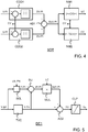
- FIG. 4 illustrates the saturation detector SDT or, rather, an example thereof.
- the saturation detector SDT receives the chrominance component pair V-PI, U-PI, which comprises a first chrominance component of interest V-PI and a second chrominance component of interest U-PI.
- the saturation detector SDT comprises various functional entities: two center deviation detectors CDDl, CDD2, an adder ADl, and two normalizers NMl, NM2.
- Center deviation detector CDDl establishes an absolute difference between the value of the first chrominance component of interest V-PI and a central value CV.
- the central value CV corresponds with an insignificant degree of saturation, that is, the central value CV is tantamount to no saturation at all.
- chrominance components have values that are comprised in a range between 0 and 255, which is typically the case if those values are expressed by means of 8 bits.
- the central value CV may be, for example, 128.
- Center deviation detector CDDl may subtract the central value CV from the value of the first chrominance component of interest V-PI and take the absolute value of the result of the subtraction, so as to obtain the absolute difference between the aforementioned values.
- the center deviation detector CDDl provides a first chrominance deviation value DV-PI, which corresponds with this absolute difference.
- center deviation detector CDD2 provides a second chrominance deviation value DU-PI, which corresponds with an absolute difference between the value of the second chrominance component of interest U-PI and the central value CV.
- Adder ADl adds the first chrominance deviation value DV-PI to the second chrominance deviation value DU-PI, which produces an overall chrominance deviation value DUV-PI.
- the overall chrominance deviation value DUV-PI represents a degree of saturation for the pixel of interest PI. The higher the overall chrominance deviation value DUV-PI is, the higher the degree of saturation is. Conversely, in case the pixel of interest PI exhibits a relatively low degree of saturation, the overall chrominance deviation value DUV-PI will be a relatively close to zero (0).
- Normalizer NM1 divides the overall chrominance deviation value DUV-PI by the central value CV. In addition, normalizer NM1 adds one unit of value (1) to the result of this division so as to obtain the luminance control value LC.
- the luminance control value LC may therefore be comprised in a range between 1 and 2. The luminance control value LC will be relatively close to 1 if the pixel of interest PI exhibits a relatively low degree of saturation and will be relatively close to 2 if the pixel of interest PI exhibits a relatively high degree of saturation.
- Normalizer NM2 divides the overall chrominance deviation value DUV-PI by half the central value CV. In addition, normalizer NM2 adds one unit of value (1) to the result of this division so as to obtain the luminance control value LC.
- the chrominance control value CC may therefore be comprised in a range between 1 and 3. That is, the chrominance control value CC may vary over a wider range than the luminance control value LC.
- the chrominance control value CC will be relatively close to 3 if the pixel of interest PI exhibits a relatively high degree of saturation. As a result, the degree of detail amplification will be higher for chrominance components than for luminance components.
- FIG. 5 illustrates detail emphasis module DE1 or, rather, an example thereof.
- Detail emphasis module DE1 comprises various functional entities: a selector SEL, a typical value calculator TVC, a subtractor SU, a multiplier MUL, an adder AD2, and a clipper CLP.
- FIG. 5 can thus be regarded to represent a method, whereby a functional entity, or a group of functional entities, can be considered as a processing step, or a series of processing steps, of this method.
- the selector SEL selects a luminance component of interest Y-PI, which is in the set of luminance components Y-SP.
- the pixel selection data LN, PN identifies the pixel of interest PI and, therefore, the luminance component of interest Y-PI.
- the typical value calculator TVC calculates a typical luminance value Y-TV on the basis of the set of luminance components Y-SP.
- the typical luminance value Y-TV may be, for example, an average of the respective values of the neighboring luminance components, which are comprised in the set.
- the typical luminance value Y-TV may be a median value.
- the subtractor SU subtracts the typical luminance value Y-TV from the value of the luminance component of interest Y-PI. Accordingly, the subtractor SU provides a luminance difference value dY-PI for the pixel of interest PI, which expresses the difference in value between the luminance component of interest Y-PI and the neighboring luminance components.
- the multiplier MUL multiplies the luminance difference value dY-PI with the luminance control value LC, which the saturation detector SDT illustrated in FIG. 4 provides.
- the result of this multiplication is an amplified luminance difference value AdY-PI.
- the luminance control value LC constitutes an amplification factor, that is, a gain value for the difference in value between the luminance component of interest Y-PI and the neighboring luminance components.
- the adder AD2 adds the typical luminance value Y-TV to the amplified luminance difference value AdY-PI so as to obtain an unbounded output luminance value YV.
- the clipper CLP assigns a value to the output luminance component Yo on the basis of the unbounded output luminance value YV.
- the value of the output luminance component Yo is equal to the unbounded output luminance value YV.
- the desired range may be comprised between, for example, 0 and 255, which represent a lower limit and an upper limit, respectively.
- the unbounded output luminance value YV is below the lower limit
- the value of the output luminance component Yo is equal to the lower limit.
- the unbounded output luminance value YV is above the upper limit
- the value of the output luminance component Yo is equal to the upper limit.
- the clipper CLP thus ensures that is the value of the output luminance component Yo is within the desired range.
- the luminance control value LC will be equal to 1, or only slightly greater than 1. In that case, the difference in value between the luminance component of interest Y-PI and the neighboring luminance components is not amplified, or only to an insignificant degree.
- the gain value is 1, or only slightly greater than 1.
- the output luminance component Yo will be substantially equal to the luminance component of interest Y-PI. There is no emphasis of any details because there is an insignificant degree of color saturation. Conversely, let it now be assumed that the pixel of interest PI exhibits a relatively high degree of color saturation. As a result, the luminance control value LC will be significantly greater than 1.
- the difference in value between the luminance component of interest Y-PI and the neighboring luminance components is amplified to a degree that depends on the degree of color saturation.
- the gain value is significantly greater than 1.
- the value of the luminance component of interest Y-PI is relatively low with respect to those of the neighboring luminance components, the value of the output luminance component Yo will be even lower than that of the luminance component of interest Y-PI.
- the value of the output luminance component Yo will be even higher than that of the luminance component of interest Y-PI.
- Detail emphasis modules DE2, DE3 are similar to detail emphasis module DE1 illustrated in FIG. 5 and operate in a similar fashion. A difference is that detail emphasis module DE2 will comprise a multiplier comparable with the multiplier MUL illustrated in FIG. 5 , which receives the chrominance control value CC instead of the luminance control value LC. The same applies to detail emphasis module DE3. Since the chrominance control value CC has a higher upper limit, namely 3, than that of the luminance control value LC, which is 2, spatial chrominance details are boosted to an even greater extent than spatial luminance details in a region where color saturation is high.
- FIG. 6 illustrates a software-based implementation of the image enhancer ENH illustrated in FIG. 2 .
- FIG. 6 is a computer code diagram that illustrates a set of instructions written in c-code, which can cause a processor to carry out operations described hereinbefore in connection with FIG. 2 , as well as those described in connection with FIGS. 3-5 .
- the set of instructions comprises respective code portions CP1-CP4 that are related to respective functional entities illustrated in the aforementioned figures and described hereinbefore.
- FIG. 6 indicates these relationships by means of reference signs: a code portion that corresponds with a functional entity illustrated in any of the FIGS. 2-5 , is provided with a reference sign corresponding to that of the functional entity concerned.
- the invention may be applied to advantage in numerous types of products or methods that involve color images.
- the invention may be applied in a portable communication apparatus that is provided with a color display, such as, for example, a cellular phone or a personal digital assistant (PDA).
- Color images which are to be enhanced, may be received in numerous different fashions.
- FIG 2 illustrates an example in which color images are received from a server via a network.
- color images may be received from a reading module that reads a data carrier, such as, for example, an optical disk, a hard disk, or a solid-state memory.
- a reading module may form part of an image rendering apparatus in which the invention is applied.
- a color image, which is enhanced in accordance with the invention need not necessarily be in a particular format.
- the detailed description provides an example in which a color image is in the so-called YUV format.
- a color image in the so-called YCrCb format or in the so-called HSV format may also be enhanced in accordance with the
- a spatial detail in an image area is emphasized to a degree that is greater as the degree of color saturation is higher.
- Emphasizing a spatial detail is tantamount to high- pass filtering.
- a spatial detail may undergo a low-pass filtering to a degree that is greater as the degree of color saturation is higher. That is, the spatial detail is deemphasized to degree that is greater as the degree of color saturation is higher.
- Such a filtering technique may be advantageous for processing, for example, a video signal obtained by reading a videocassette of the VHS type.
- color information is stored by means of a modulation technique that causes relatively strong noise in saturated color planes.
- This noise can be reduced by applying a degree of low-pass filtering that is greater as the degree of color saturation in the plane concerned is greater.
- Perceptual image quality will improve.
- This may also be obtained by applying a degree of high-pass filtering that is greater as the degree of color saturation in the plane concerned is lower.
- details are emphasized only in image areas where color saturation is relatively low, which avoids an emphasis of color noise that would otherwise adversely affect perceptual image quality.
- There are numerous ways of filtering spatial details in image are numerous ways of filtering spatial details in image.
- a filter arrangement may detect particular sets of pixels that represent details, such as, for example, a set of pixels around a border of an object. The filter arrangement may then amplify highfrequency components that are present in such a set of pixels. For example, high-pass filtering may selectively be applied to areas in image that comprise relatively many details and in which colors are saturated to relatively high degree. Frequency analysis techniques may be used to identify areas that comprise relatively many details.
- image should be understood in a broad sense.
- the term includes any element that can be visually rendered, such as, for example, a picture, a frame, or a field.
- filtering should be understood in a broad sense. This term includes any type of processing by means of which one property of a pixel of interest, or a group of pixels of interest, is modified in dependence on other pixels that have neighboring positions, either spatially or temporally, or both.
- a medium in which software stored may be supplied as an individual product or together with another product, which may execute software. Such a medium may also be part of a product that enables software to be executed.
- Software may also be distributed via communication networks, which may be wired, wireless, or hybrid. For example, software may be distributed via the Internet. Software may be made available for download by means of a server. Downloading may be subject to a payment.
Claims (8)
- Verfahren zur Bildverbesserung, enthaltend:einen Sättigungserfassungsschritt (SDT), bei welchem ein Ausmaß der Farbsättigung eines Pixels von Interesse (PI) erfasst wird und bei welchem ein Luminanzsteuerwert (LC) und ein Chrominanzsteuerwert (CC) für das Pixel von Interesse (PI) erzeugt werden,wobei die Steuerwerte (LC, CC) größer sind, wenn das Ausmaß der Farbsättigung des Pixels von Interesse größer ist, undwobei der Chrominanzsteuerwert (CC) größer ist als der Luminanzsteuerwert (LC); undeinen Detailhervorhebungsschritt (DE1, DE2, DE3), bei welchem mindestens ein räumliches Detail in einem einer das Pixel von Interesse (PI) und seine benachbarten Pixel enthaltenden Gruppe von Pixeln (SP) entsprechenden Bildbereich in einem Ausmaß hervorgehoben wird, das von dem Ausmaß der Farbsättigung des Pixels von Interesse (PI) abhängig ist, wobei der Detailhervorhebungsschritt (DE1, DE2, DE3) enthält:einen Subtraktionsunterschritt (SU)zum Berechnen einer Differenz (dY-PI) zwischen einem Luminanzwert (Y-PI) des Pixels von Interesse (PI) und einem typischen Luminanzwert (Y-TV), der aus den benachbarten Pixeln in der Gruppe von Pixeln (SP) berechnet wird, undzum Berechnen von Differenzen zwischen Chrominanzwerten (U-PI, V-PI) des Pixels von Interesse (PI) und jeweiligen typischen Chrominanzwerten, die aus den benachbarten Pixeln in der Gruppe von Pixeln (SP) berechnet werden;einen Multiplikationsunterschritt (MUL)zum Multiplizieren der Differenz der Luminanz (dY-PI) mit dem Luminanzsteuerwert (LC) undzum Multiplizieren der Differenzen der Chrominanz mit dem Chrominanzsteuerwert (CC); undeinen Additionsunterschritt (AD2)zum Addieren des typischen Luminanzwerts zu der multiplizierten Luminanzdifferenz (AdY-PI) undzum Addieren des typischen Chrominanzwerts zu den jeweiligen multiplizierten Chrominanzdifferenzen,um so einen modifizierten Wert für das Pixel von Interesse (PI) zu erhalten.
- Verfahren nach Anspruch 1, wobei der Sättigungserfassungsschritt (SDT) die folgenden Unterschritte enthält:einen Mittenabweichungerfassungs-Unterschritt (CDD1, CDD2), bei welchem absolute Differenzen (DV-PI, DU-PI) zwischen den Chrominanzwerten (V-PI, U-PI) des Pixels von Interesse (PI) und einem Mittenwert (CV), der einem insignifikanten Ausmaß der Sättigung entspricht, ermittelt werden; undeinen Steuerwerterzeugungs-Unterschritt (ADI, NMI, NM2), bei welchem die Steuerwerte (LC, CC) auf der Grundlage der absoluten Differenz (DV-PI, DU-PI) erzeugt werden.
- Verfahren nach Anspruch 1, wobei der Detailhervorhebungsschritt (D1, D2, D3) enthält:
einen Unterschritt zur Berechnung eines typischen Werts (TVC), bei welchem der typische Luminanzwert (Y-TV) und die typischen Chrominanzwerte ermittelt werden. - Verfahren nach Anspruch 1, enthaltend:
einen Sequenzierungsschritt (SQ), bei welchem jeweilige Pixel in einem Farbbild sukzessive einzeln nacheinander als das Pixel von Interesse (PI) bezeichnet werden. - Verfahren nach Anspruch 1, enthaltend:
einen Pixelauswahlschritt (PSR), bei welchem die Gruppe von Pixeln (SP) auf der Grundlage einer vordefinierten Apertur (ABE) gebildet wird. - Bildverbesserungsvorrichtung (ENH), enthaltend:eine Sättigungserfassungseinrichtung (SDP), die so angeordnet ist, dass sie ein Ausmaß der Farbsättigung eines Pixels von Interesse (PI) ermittelt und einen Luminanzsteuerwert (LC) und einen Chrominanzsteuerwert (CC) für das Pixel von Interesse (PI) erzeugt,wobei die Steuerwerte (LC, CC) größer sind, wenn das Ausmaß der Farbsättigung des Pixels von Interesse größer ist, undwobei der Chrominanzsteuerwert (CC) größer ist als der Luminanzsteuerwert (LC); undDetailhervorhebungsmodule (DE1, DE2, DE3), die so angeordnet sind, dass sie mindestens ein räumliches Detail in einem einer das Pixel von Interesse (PI) und seine benachbarten Pixel enthaltenden Gruppe von Pixeln (SP) entsprechenden Bildbereich in einem Ausmaß hervorheben, das von dem Ausmaß der Farbsättigung des Pixels von Interesse (PI) abhängig ist, wobei jedes Detailhervorhebungsmodul (DE1, DE2, DE3) enthält:eine Subtraktionseinrichtung (SU)zum Berechnen einer Differenz (dY-PI) zwischen einem Luminanzwert (Y-PI) des Pixels von Interesse (PI) und einem typischen Luminanzwert (Y-TV), der aus den benachbarten Pixeln in der Gruppe von Pixeln (SP) berechnet wird, undzum Berechnen von Differenzen zwischen Chrominanzwerten (U-PI, V-PI) des Pixels von Interesse (PI) und jeweiligen typischen Chrominanzwerten, die aus den benachbarten Pixeln in der Gruppe von Pixeln (SP) berechnet werden;eine Multiplikationseinrichtung (MUL)zum Multiplizieren der Differenz der Luminanz (dY-PI) mit dem Luminanzsteuerwert (LC) undzum Multiplizieren der Differenzen der Chrominanz mit dem Chrominanzsteuerwert (CC); undeine Additionseinrichtung (AD2)zum Addieren des typischen Luminanzwerts zu der multiplizierten Luminanzdifferenz (AdY-PI) undzum Addieren des typischen Chrominanzwerts zu den jeweiligen multiplizierten Chrominanzdifferenzen,um so einen modifizierten Wert für das Pixel von Interesse (PI) zu erhalten.
- Bildrenderingsystem (ERS), enthaltend
eine Bildverbesserungseinrichtung (ENH) nach Anspruch 6 zur Verarbeitung eines Farbbilds, um so ein verbessertes Farbbild zu erhalten, und eine Anzeigeeinrichtung (DPL) zum Anzeigen des verbesserten Farbbilds. - Computerprogrammprodukt für einen programmierbaren Prozessor, welches Computerprogrammprodukt eine Gruppe von Anweisungen enthält, die bei der Ausführung durch den programmierbaren Prozessor den programmierbaren Prozessor veranlassen, das Verfahren nach Anspruch 1 auszuführen.
Priority Applications (1)
| Application Number | Priority Date | Filing Date | Title |
|---|---|---|---|
| EP09719008.6A EP2266096B1 (de) | 2008-03-13 | 2009-03-10 | Verfahren und vorrichtung zur verbesserung der wahrnehmungsqualität von farbbildern |
Applications Claiming Priority (3)
| Application Number | Priority Date | Filing Date | Title |
|---|---|---|---|
| EP08305055 | 2008-03-13 | ||
| EP09719008.6A EP2266096B1 (de) | 2008-03-13 | 2009-03-10 | Verfahren und vorrichtung zur verbesserung der wahrnehmungsqualität von farbbildern |
| PCT/IB2009/051001 WO2009113023A1 (en) | 2008-03-13 | 2009-03-10 | Color image enhancement |
Publications (2)
| Publication Number | Publication Date |
|---|---|
| EP2266096A1 EP2266096A1 (de) | 2010-12-29 |
| EP2266096B1 true EP2266096B1 (de) | 2020-04-29 |
Family
ID=40718549
Family Applications (1)
| Application Number | Title | Priority Date | Filing Date |
|---|---|---|---|
| EP09719008.6A Active EP2266096B1 (de) | 2008-03-13 | 2009-03-10 | Verfahren und vorrichtung zur verbesserung der wahrnehmungsqualität von farbbildern |
Country Status (6)
| Country | Link |
|---|---|
| US (1) | US9196019B2 (de) |
| EP (1) | EP2266096B1 (de) |
| JP (1) | JP5593515B2 (de) |
| KR (1) | KR101598555B1 (de) |
| CN (1) | CN101999137B (de) |
| WO (1) | WO2009113023A1 (de) |
Families Citing this family (4)
| Publication number | Priority date | Publication date | Assignee | Title |
|---|---|---|---|---|
| KR101294854B1 (ko) | 2010-12-22 | 2013-08-08 | 엘지디스플레이 주식회사 | 비젼 시스템과 이를 이용한 입체영상 표시장치의 표시패널과 패턴 리타더 정렬 시스템 |
| JP5972312B2 (ja) * | 2014-03-24 | 2016-08-17 | 富士フイルム株式会社 | 医用画像処理装置及びその作動方法 |
| US10132860B2 (en) | 2016-10-28 | 2018-11-20 | Nxp Usa, Inc. | Systems and methods for testing package assemblies |
| CN112911366B (zh) * | 2019-12-03 | 2023-10-27 | 海信视像科技股份有限公司 | 饱和度调整方法、装置及显示设备 |
Family Cites Families (26)
| Publication number | Priority date | Publication date | Assignee | Title |
|---|---|---|---|---|
| IE76718B1 (en) | 1987-08-03 | 1997-11-19 | American Film Tech | System and method for color image enhancement |
| JPH0382273A (ja) | 1989-08-25 | 1991-04-08 | Toshiba Corp | 撮像装置の輪郭補正回路 |
| US5517335A (en) * | 1994-10-11 | 1996-05-14 | Seiko Epson Corporation | Apparatus and method for enhancing color saturation in halftoned images |
| US5982926A (en) | 1995-01-17 | 1999-11-09 | At & T Ipm Corp. | Real-time image enhancement techniques |
| KR100202566B1 (ko) | 1996-03-25 | 1999-06-15 | 구자홍 | 칼라영상의 선명도 향상장치 |
| US6449060B1 (en) | 1996-07-22 | 2002-09-10 | Canon Kabushiki Kaisha | Image processing apparatus and method |
| JPH1040373A (ja) | 1996-07-22 | 1998-02-13 | Canon Inc | 画像処理装置及び方法 |
| JP3736632B2 (ja) * | 1996-11-21 | 2006-01-18 | セイコーエプソン株式会社 | 画像処理装置、画像処理方法および画像処理プログラムを記録した媒体 |
| US6400371B1 (en) * | 1997-05-16 | 2002-06-04 | Liberate Technologies | Television signal chrominance adjustment |
| JP3699873B2 (ja) | 1999-10-27 | 2005-09-28 | オリンパス株式会社 | 画像処理装置 |
| JP2002033934A (ja) * | 2000-07-18 | 2002-01-31 | Fuji Photo Film Co Ltd | 画像処理装置及び方法 |
| US6809838B1 (en) | 2000-10-19 | 2004-10-26 | Eastman Kodak Company | Transforms for display or printing digital images |
| JP4666274B2 (ja) | 2001-02-20 | 2011-04-06 | 日本電気株式会社 | カラー画像処理装置及びその方法 |
| JP4111689B2 (ja) * | 2001-04-24 | 2008-07-02 | シャープ株式会社 | 画像処理装置、画像処理プログラムを記録したコンピュータ読取可能な記録媒体およびプログラム |
| EP1370091A1 (de) * | 2002-06-06 | 2003-12-10 | Koninklijke Philips Electronics N.V. | Bildverarbeitung |
| US7221793B2 (en) * | 2003-05-27 | 2007-05-22 | Hewlett-Packard Development Company, L.P. | Systems and methods for providing spatially-varied demosaicing |
| CN1266950C (zh) * | 2003-11-10 | 2006-07-26 | 华亚微电子(上海)有限公司 | 一种视频图像的品质增强系统与方法 |
| KR100561852B1 (ko) * | 2003-11-20 | 2006-03-16 | 삼성전자주식회사 | 색 신호의 밝기 보상 방법 및 장치 |
| KR100542365B1 (ko) | 2004-05-07 | 2006-01-10 | 삼성전자주식회사 | 영상 화질 개선 장치 및 그 방법 |
| WO2006025120A1 (ja) * | 2004-09-01 | 2006-03-09 | Mitsubishi Denki Kabushiki Kaisha | 画像表示装置および画像表示方法 |
| JP4822773B2 (ja) * | 2004-09-13 | 2011-11-24 | キヤノン株式会社 | 色ノイズ低減回路及びそれを用いた撮像装置 |
| US7483082B2 (en) | 2005-04-21 | 2009-01-27 | Kolorific, Inc. | Method and system for automatic color hue and color saturation adjustment of a pixel from a video source |
| JP2007104151A (ja) * | 2005-09-30 | 2007-04-19 | Sanyo Electric Co Ltd | 画像処理装置および画像処理プログラム |
| US7773158B2 (en) * | 2005-10-12 | 2010-08-10 | Panasonic Corporation | Visual processing device, display device, and integrated circuit |
| JP2008042392A (ja) * | 2006-08-03 | 2008-02-21 | Matsushita Electric Ind Co Ltd | 画像処理装置及び方法 |
| US8570341B1 (en) * | 2007-12-07 | 2013-10-29 | Ipera Technology, Inc. | Method and system for enhancing color saturation |
-
2009
- 2009-03-10 CN CN2009801087758A patent/CN101999137B/zh not_active Expired - Fee Related
- 2009-03-10 KR KR1020107022635A patent/KR101598555B1/ko active IP Right Grant
- 2009-03-10 US US12/919,777 patent/US9196019B2/en active Active
- 2009-03-10 WO PCT/IB2009/051001 patent/WO2009113023A1/en active Application Filing
- 2009-03-10 JP JP2010550317A patent/JP5593515B2/ja active Active
- 2009-03-10 EP EP09719008.6A patent/EP2266096B1/de active Active
Non-Patent Citations (1)
| Title |
|---|
| None * |
Also Published As
| Publication number | Publication date |
|---|---|
| JP2011516911A (ja) | 2011-05-26 |
| WO2009113023A1 (en) | 2009-09-17 |
| KR101598555B1 (ko) | 2016-02-29 |
| US20110002540A1 (en) | 2011-01-06 |
| KR20100132520A (ko) | 2010-12-17 |
| CN101999137B (zh) | 2013-07-10 |
| EP2266096A1 (de) | 2010-12-29 |
| CN101999137A (zh) | 2011-03-30 |
| JP5593515B2 (ja) | 2014-09-24 |
| US9196019B2 (en) | 2015-11-24 |
Similar Documents
| Publication | Publication Date | Title |
|---|---|---|
| US10467735B2 (en) | Inverse tone mapping based on luminance zones | |
| KR102523505B1 (ko) | 역 톤 매핑을 위한 방법 및 장치 | |
| EP0971314B1 (de) | Verfahren zur Erhaltung von Bilddetails bei Kontrastveränderung | |
| KR101311817B1 (ko) | 이미지 디테일 향상 | |
| JP2007208399A (ja) | 画像処理装置、画像処理方法、画像処理方法のプログラム及び画像処理方法のプログラムを記録した記録媒体 | |
| US20090002562A1 (en) | Image Processing Device, Image Processing Method, Program for Image Processing Method, and Recording Medium Having Program for Image Processing Method Recorded Thereon | |
| US8427560B2 (en) | Image processing device | |
| EP2266096B1 (de) | Verfahren und vorrichtung zur verbesserung der wahrnehmungsqualität von farbbildern | |
| US8036459B2 (en) | Image processing apparatus | |
| US10771755B2 (en) | Image processing apparatus, image processing method, and program | |
| JP2008033592A (ja) | 画像処理装置および画像処理方法、並びにプログラム | |
| JP6335614B2 (ja) | 画像処理装置、その制御方法、及びプログラム | |
| US20100295996A1 (en) | Circuit and method for image processing | |
| TWI390958B (zh) | 影像濾波電路及應用其之影像處理電路及影像處理方法 | |
| JP2011254376A (ja) | 画像処理装置、撮像装置及び画像処理プログラム | |
| WO2006123290A2 (en) | Image processor comprising a contrast enhancer | |
| JP2010220063A (ja) | 画像処理装置及び方法並びに画像表示装置 | |
| JP2010147971A (ja) | 画像処理装置及び方法並びに画像表示装置 |
Legal Events
| Date | Code | Title | Description |
|---|---|---|---|
| PUAI | Public reference made under article 153(3) epc to a published international application that has entered the european phase |
Free format text: ORIGINAL CODE: 0009012 |
|
| 17P | Request for examination filed |
Effective date: 20101013 |
|
| AK | Designated contracting states |
Kind code of ref document: A1 Designated state(s): AT BE BG CH CY CZ DE DK EE ES FI FR GB GR HR HU IE IS IT LI LT LU LV MC MK MT NL NO PL PT RO SE SI SK TR |
|
| AX | Request for extension of the european patent |
Extension state: AL BA RS |
|
| DAX | Request for extension of the european patent (deleted) | ||
| RAP1 | Party data changed (applicant data changed or rights of an application transferred) |
Owner name: NXP B.V. Owner name: TP VISION HOLDING B.V. |
|
| RAP1 | Party data changed (applicant data changed or rights of an application transferred) |
Owner name: TP VISION HOLDING B.V. Owner name: NXP B.V. |
|
| 17Q | First examination report despatched |
Effective date: 20141107 |
|
| RIC1 | Information provided on ipc code assigned before grant |
Ipc: H04N 5/208 20060101AFI20190930BHEP Ipc: H04N 9/64 20060101ALN20190930BHEP Ipc: H04N 1/409 20060101ALN20190930BHEP |
|
| REG | Reference to a national code |
Ref country code: DE Ref legal event code: R079 Ref document number: 602009061876 Country of ref document: DE Free format text: PREVIOUS MAIN CLASS: G06T0005000000 Ipc: H04N0005208000 |
|
| RIC1 | Information provided on ipc code assigned before grant |
Ipc: H04N 1/409 20060101ALN20191030BHEP Ipc: H04N 5/208 20060101AFI20191030BHEP Ipc: H04N 9/64 20060101ALN20191030BHEP |
|
| GRAP | Despatch of communication of intention to grant a patent |
Free format text: ORIGINAL CODE: EPIDOSNIGR1 |
|
| RIC1 | Information provided on ipc code assigned before grant |
Ipc: H04N 5/208 20060101AFI20191111BHEP Ipc: H04N 9/64 20060101ALN20191111BHEP Ipc: H04N 1/409 20060101ALN20191111BHEP |
|
| STAA | Information on the status of an ep patent application or granted ep patent |
Free format text: STATUS: GRANT OF PATENT IS INTENDED |
|
| INTG | Intention to grant announced |
Effective date: 20191219 |
|
| GRAS | Grant fee paid |
Free format text: ORIGINAL CODE: EPIDOSNIGR3 |
|
| GRAA | (expected) grant |
Free format text: ORIGINAL CODE: 0009210 |
|
| STAA | Information on the status of an ep patent application or granted ep patent |
Free format text: STATUS: THE PATENT HAS BEEN GRANTED |
|
| AK | Designated contracting states |
Kind code of ref document: B1 Designated state(s): AT BE BG CH CY CZ DE DK EE ES FI FR GB GR HR HU IE IS IT LI LT LU LV MC MK MT NL NO PL PT RO SE SI SK TR |
|
| REG | Reference to a national code |
Ref country code: GB Ref legal event code: FG4D |
|
| REG | Reference to a national code |
Ref country code: CH Ref legal event code: EP |
|
| REG | Reference to a national code |
Ref country code: DE Ref legal event code: R096 Ref document number: 602009061876 Country of ref document: DE |
|
| REG | Reference to a national code |
Ref country code: AT Ref legal event code: REF Ref document number: 1265060 Country of ref document: AT Kind code of ref document: T Effective date: 20200515 |
|
| REG | Reference to a national code |
Ref country code: IE Ref legal event code: FG4D |
|
| REG | Reference to a national code |
Ref country code: NL Ref legal event code: FP |
|
| REG | Reference to a national code |
Ref country code: LT Ref legal event code: MG4D |
|
| PG25 | Lapsed in a contracting state [announced via postgrant information from national office to epo] |
Ref country code: GR Free format text: LAPSE BECAUSE OF FAILURE TO SUBMIT A TRANSLATION OF THE DESCRIPTION OR TO PAY THE FEE WITHIN THE PRESCRIBED TIME-LIMIT Effective date: 20200730 Ref country code: FI Free format text: LAPSE BECAUSE OF FAILURE TO SUBMIT A TRANSLATION OF THE DESCRIPTION OR TO PAY THE FEE WITHIN THE PRESCRIBED TIME-LIMIT Effective date: 20200429 Ref country code: LT Free format text: LAPSE BECAUSE OF FAILURE TO SUBMIT A TRANSLATION OF THE DESCRIPTION OR TO PAY THE FEE WITHIN THE PRESCRIBED TIME-LIMIT Effective date: 20200429 Ref country code: NO Free format text: LAPSE BECAUSE OF FAILURE TO SUBMIT A TRANSLATION OF THE DESCRIPTION OR TO PAY THE FEE WITHIN THE PRESCRIBED TIME-LIMIT Effective date: 20200729 Ref country code: SE Free format text: LAPSE BECAUSE OF FAILURE TO SUBMIT A TRANSLATION OF THE DESCRIPTION OR TO PAY THE FEE WITHIN THE PRESCRIBED TIME-LIMIT Effective date: 20200429 Ref country code: PT Free format text: LAPSE BECAUSE OF FAILURE TO SUBMIT A TRANSLATION OF THE DESCRIPTION OR TO PAY THE FEE WITHIN THE PRESCRIBED TIME-LIMIT Effective date: 20200831 Ref country code: IS Free format text: LAPSE BECAUSE OF FAILURE TO SUBMIT A TRANSLATION OF THE DESCRIPTION OR TO PAY THE FEE WITHIN THE PRESCRIBED TIME-LIMIT Effective date: 20200829 |
|
| REG | Reference to a national code |
Ref country code: AT Ref legal event code: MK05 Ref document number: 1265060 Country of ref document: AT Kind code of ref document: T Effective date: 20200429 |
|
| PG25 | Lapsed in a contracting state [announced via postgrant information from national office to epo] |
Ref country code: BG Free format text: LAPSE BECAUSE OF FAILURE TO SUBMIT A TRANSLATION OF THE DESCRIPTION OR TO PAY THE FEE WITHIN THE PRESCRIBED TIME-LIMIT Effective date: 20200729 Ref country code: HR Free format text: LAPSE BECAUSE OF FAILURE TO SUBMIT A TRANSLATION OF THE DESCRIPTION OR TO PAY THE FEE WITHIN THE PRESCRIBED TIME-LIMIT Effective date: 20200429 Ref country code: LV Free format text: LAPSE BECAUSE OF FAILURE TO SUBMIT A TRANSLATION OF THE DESCRIPTION OR TO PAY THE FEE WITHIN THE PRESCRIBED TIME-LIMIT Effective date: 20200429 |
|
| REG | Reference to a national code |
Ref country code: NL Ref legal event code: PD Owner name: TOP VICTORY INVESTMENTS LIMITED; HK Free format text: DETAILS ASSIGNMENT: CHANGE OF OWNER(S), ASSIGNMENT; FORMER OWNER NAME: TP VISION HOLDING B.V. Effective date: 20201203 |
|
| PG25 | Lapsed in a contracting state [announced via postgrant information from national office to epo] |
Ref country code: EE Free format text: LAPSE BECAUSE OF FAILURE TO SUBMIT A TRANSLATION OF THE DESCRIPTION OR TO PAY THE FEE WITHIN THE PRESCRIBED TIME-LIMIT Effective date: 20200429 Ref country code: IT Free format text: LAPSE BECAUSE OF FAILURE TO SUBMIT A TRANSLATION OF THE DESCRIPTION OR TO PAY THE FEE WITHIN THE PRESCRIBED TIME-LIMIT Effective date: 20200429 Ref country code: RO Free format text: LAPSE BECAUSE OF FAILURE TO SUBMIT A TRANSLATION OF THE DESCRIPTION OR TO PAY THE FEE WITHIN THE PRESCRIBED TIME-LIMIT Effective date: 20200429 Ref country code: AT Free format text: LAPSE BECAUSE OF FAILURE TO SUBMIT A TRANSLATION OF THE DESCRIPTION OR TO PAY THE FEE WITHIN THE PRESCRIBED TIME-LIMIT Effective date: 20200429 Ref country code: DK Free format text: LAPSE BECAUSE OF FAILURE TO SUBMIT A TRANSLATION OF THE DESCRIPTION OR TO PAY THE FEE WITHIN THE PRESCRIBED TIME-LIMIT Effective date: 20200429 Ref country code: CZ Free format text: LAPSE BECAUSE OF FAILURE TO SUBMIT A TRANSLATION OF THE DESCRIPTION OR TO PAY THE FEE WITHIN THE PRESCRIBED TIME-LIMIT Effective date: 20200429 Ref country code: ES Free format text: LAPSE BECAUSE OF FAILURE TO SUBMIT A TRANSLATION OF THE DESCRIPTION OR TO PAY THE FEE WITHIN THE PRESCRIBED TIME-LIMIT Effective date: 20200429 |
|
| REG | Reference to a national code |
Ref country code: DE Ref legal event code: R097 Ref document number: 602009061876 Country of ref document: DE |
|
| PG25 | Lapsed in a contracting state [announced via postgrant information from national office to epo] |
Ref country code: SK Free format text: LAPSE BECAUSE OF FAILURE TO SUBMIT A TRANSLATION OF THE DESCRIPTION OR TO PAY THE FEE WITHIN THE PRESCRIBED TIME-LIMIT Effective date: 20200429 Ref country code: PL Free format text: LAPSE BECAUSE OF FAILURE TO SUBMIT A TRANSLATION OF THE DESCRIPTION OR TO PAY THE FEE WITHIN THE PRESCRIBED TIME-LIMIT Effective date: 20200429 |
|
| PLBE | No opposition filed within time limit |
Free format text: ORIGINAL CODE: 0009261 |
|
| STAA | Information on the status of an ep patent application or granted ep patent |
Free format text: STATUS: NO OPPOSITION FILED WITHIN TIME LIMIT |
|
| 26N | No opposition filed |
Effective date: 20210201 |
|
| PG25 | Lapsed in a contracting state [announced via postgrant information from national office to epo] |
Ref country code: SI Free format text: LAPSE BECAUSE OF FAILURE TO SUBMIT A TRANSLATION OF THE DESCRIPTION OR TO PAY THE FEE WITHIN THE PRESCRIBED TIME-LIMIT Effective date: 20200429 |
|
| REG | Reference to a national code |
Ref country code: GB Ref legal event code: 732E Free format text: REGISTERED BETWEEN 20210708 AND 20210714 |
|
| PG25 | Lapsed in a contracting state [announced via postgrant information from national office to epo] |
Ref country code: MC Free format text: LAPSE BECAUSE OF FAILURE TO SUBMIT A TRANSLATION OF THE DESCRIPTION OR TO PAY THE FEE WITHIN THE PRESCRIBED TIME-LIMIT Effective date: 20200429 |
|
| REG | Reference to a national code |
Ref country code: CH Ref legal event code: PL |
|
| REG | Reference to a national code |
Ref country code: DE Ref legal event code: R081 Ref document number: 602009061876 Country of ref document: DE Owner name: TOP VICTORY INVESTMENTS LIMITED, KWUN TONG, HK Free format text: FORMER OWNERS: NXP B.V., EINDHOVEN, NL; TP VISION HOLDING B.V., AMSTERDAM, NL Ref country code: DE Ref legal event code: R081 Ref document number: 602009061876 Country of ref document: DE Owner name: NXP B.V., NL Free format text: FORMER OWNERS: NXP B.V., EINDHOVEN, NL; TP VISION HOLDING B.V., AMSTERDAM, NL Ref country code: DE Ref legal event code: R082 Ref document number: 602009061876 Country of ref document: DE |
|
| REG | Reference to a national code |
Ref country code: BE Ref legal event code: MM Effective date: 20210331 |
|
| PG25 | Lapsed in a contracting state [announced via postgrant information from national office to epo] |
Ref country code: IE Free format text: LAPSE BECAUSE OF NON-PAYMENT OF DUE FEES Effective date: 20210310 Ref country code: CH Free format text: LAPSE BECAUSE OF NON-PAYMENT OF DUE FEES Effective date: 20210331 Ref country code: LI Free format text: LAPSE BECAUSE OF NON-PAYMENT OF DUE FEES Effective date: 20210331 Ref country code: LU Free format text: LAPSE BECAUSE OF NON-PAYMENT OF DUE FEES Effective date: 20210310 |
|
| PG25 | Lapsed in a contracting state [announced via postgrant information from national office to epo] |
Ref country code: BE Free format text: LAPSE BECAUSE OF NON-PAYMENT OF DUE FEES Effective date: 20210331 |
|
| PGFP | Annual fee paid to national office [announced via postgrant information from national office to epo] |
Ref country code: FR Payment date: 20230216 Year of fee payment: 15 |
|
| PG25 | Lapsed in a contracting state [announced via postgrant information from national office to epo] |
Ref country code: HU Free format text: LAPSE BECAUSE OF FAILURE TO SUBMIT A TRANSLATION OF THE DESCRIPTION OR TO PAY THE FEE WITHIN THE PRESCRIBED TIME-LIMIT; INVALID AB INITIO Effective date: 20090310 Ref country code: CY Free format text: LAPSE BECAUSE OF FAILURE TO SUBMIT A TRANSLATION OF THE DESCRIPTION OR TO PAY THE FEE WITHIN THE PRESCRIBED TIME-LIMIT Effective date: 20200429 |
|
| PGFP | Annual fee paid to national office [announced via postgrant information from national office to epo] |
Ref country code: NL Payment date: 20240326 Year of fee payment: 16 |
|
| PG25 | Lapsed in a contracting state [announced via postgrant information from national office to epo] |
Ref country code: MK Free format text: LAPSE BECAUSE OF FAILURE TO SUBMIT A TRANSLATION OF THE DESCRIPTION OR TO PAY THE FEE WITHIN THE PRESCRIBED TIME-LIMIT Effective date: 20200429 |
|
| PGFP | Annual fee paid to national office [announced via postgrant information from national office to epo] |
Ref country code: DE Payment date: 20240222 Year of fee payment: 16 Ref country code: GB Payment date: 20240219 Year of fee payment: 16 |