EP2266005B1 - Procede de determination du pronostic de fonctionnement d'un systeme - Google Patents
Procede de determination du pronostic de fonctionnement d'un systeme Download PDFInfo
- Publication number
- EP2266005B1 EP2266005B1 EP09728167.9A EP09728167A EP2266005B1 EP 2266005 B1 EP2266005 B1 EP 2266005B1 EP 09728167 A EP09728167 A EP 09728167A EP 2266005 B1 EP2266005 B1 EP 2266005B1
- Authority
- EP
- European Patent Office
- Prior art keywords
- trend
- forecast
- points
- measurements
- prognosis
- Prior art date
- Legal status (The legal status is an assumption and is not a legal conclusion. Google has not performed a legal analysis and makes no representation as to the accuracy of the status listed.)
- Active
Links
Images


Classifications
-
- G—PHYSICS
- G05—CONTROLLING; REGULATING
- G05B—CONTROL OR REGULATING SYSTEMS IN GENERAL; FUNCTIONAL ELEMENTS OF SUCH SYSTEMS; MONITORING OR TESTING ARRANGEMENTS FOR SUCH SYSTEMS OR ELEMENTS
- G05B23/00—Testing or monitoring of control systems or parts thereof
- G05B23/02—Electric testing or monitoring
- G05B23/0205—Electric testing or monitoring by means of a monitoring system capable of detecting and responding to faults
- G05B23/0259—Electric testing or monitoring by means of a monitoring system capable of detecting and responding to faults characterized by the response to fault detection
- G05B23/0283—Predictive maintenance, e.g. involving the monitoring of a system and, based on the monitoring results, taking decisions on the maintenance schedule of the monitored system; Estimating remaining useful life [RUL]
-
- G—PHYSICS
- G06—COMPUTING; CALCULATING OR COUNTING
- G06Q—INFORMATION AND COMMUNICATION TECHNOLOGY [ICT] SPECIALLY ADAPTED FOR ADMINISTRATIVE, COMMERCIAL, FINANCIAL, MANAGERIAL OR SUPERVISORY PURPOSES; SYSTEMS OR METHODS SPECIALLY ADAPTED FOR ADMINISTRATIVE, COMMERCIAL, FINANCIAL, MANAGERIAL OR SUPERVISORY PURPOSES, NOT OTHERWISE PROVIDED FOR
- G06Q10/00—Administration; Management
- G06Q10/06—Resources, workflows, human or project management; Enterprise or organisation planning; Enterprise or organisation modelling
- G06Q10/063—Operations research, analysis or management
- G06Q10/0639—Performance analysis of employees; Performance analysis of enterprise or organisation operations
- G06Q10/06393—Score-carding, benchmarking or key performance indicator [KPI] analysis
Definitions
- the present invention relates to a method for determining the operational prognosis of a system, in real time, from an environmental value of this system.
- the present invention finds particularly advantageous, but not exclusive, applications in the field of aeronautics, nuclear, naval, automotive, petrochemicals ....
- An object of the invention is to optimize the maintenance of a system under surveillance by determining in real time the failure of this system. Another object of the invention is to embark the monitoring device in the system to be monitored. The invention also aims to determine in real time the end-of-life prognosis of the system under surveillance.
- TSMD Time Stress Measurement Device
- the first set measures, over time, environmental or factual quantities, the system to be monitored, such as temperature, humidity, vibrations, shocks, etc.
- the first set includes a memory enabling the values of the values to be recorded. measured quantities.
- the stored measurements are transferred, in particular in digital form, to the second set, which is a processing unit.
- the second set analyzes the recorded values to provide a system diagnosis. From all these recorded values, the processing unit extracts information on the consumed lifetime of the system to be monitored.
- the recorded data are recovered and analyzed by the processing unit only when a complete profile is obtained. For example, a complete profile can be obtained after 350 hours of flight. Thus, a significant amount of time is observed before the recorded data is transferred to the processing unit.
- the results provided by the treatment unit are not immediate. Indeed, the amount of data to be analyzed is such that it takes several days to obtain a percentage of consumed life of the system to monitor. Therefore, this result on failures of the monitored system is not adequate.
- the computing resource requirements as well as the memory resource requirements are relatively important. As a result, the processing unit can not be shipped.
- a monitoring tool very close to the TSMD, which however has smarter functions capable of perform detections of predefined critical thresholds and alarm the user.
- a HUMS Health and Usage Monitoring System
- a HUMS is thus a device able, by its diagnosis (usually succinct), to help the user in the maintenance of his equipment.
- the problem to be solved is therefore, knowing the diagnosis of a system, including an embedded system, to establish a prognosis, a date of end of life, preferably cautious (so at a date before a real end of life ), and thus produce an alarm signal well before the present time becomes greater than this prognosis.
- HUMS only report crossing the critical threshold, when it may be too late because the monitored system will not be serviced for a long time.
- TSMD HUMS
- LAMS software embedded in the program memory of the system to be monitored itself. It can also perform among other things the measurement of its temperature, its relative humidity, as well as shocks (three-axis accelerometer) and vibrations it undergoes.
- sensor modules in large numbers (250 today but this number is extensible), especially for low frequency measurement channels, ie for temperature, relative humidity, pressure .
- the tool programmed in TSMD must be configured before starting its monitoring.
- the only information necessary for its operation are the different measurement frequencies according to each sensor. It is possible to directly implement this information in the TSMD operating system and to be a default configuration for a particular application. In this case, all that is needed is to place the TSMD and the sensor modules as close as possible to the elements to be monitored, to feed the assembly and to start monitoring. It is also possible to download this information before starting monitoring, but this involves connecting the TSMD to a microcomputer via a serial link cable.
- the on-board diagnosis and prognosis and in real time, have been developed according to a specific methodology.
- a unit damage can be affected by referring to a matrix containing simulation results (or feedback).
- the sum of this unit damage provides an estimate of the state of health and therefore a diagnosis of the electronic system under surveillance. Successive rounding involved in the calculations may lead to a diagnosis of optimistic value and a pessimistic value.
- the associated damage is accumulated to take into account their interactions.
- the invention relates to the development and integration of the LAMS function.
- the calculation of the diagnosis (which may be a percentage of damage for example) can, by studying its evolution over time, allow to estimate the date of failure of the monitored system.
- ARIMA autoregressive integrated moving average
- these statistical forecasting techniques are not particularly relevant or adapted to on-board computing and in real time (with few computing resources).
- the ARIMA model although highly successful, requires identifying the number of delays and coefficients that should be used, and is too demanding in terms of resources.
- Linear regression on the other hand, can be completely false since the evolution is not linear. And experience shows that the evolution of diagnosis is rarely linear in a real environment.
- the pieces can be determined by measuring the linear correlation coefficient. As soon as it exceeds a threshold, we decide to create another piece. Or the pieces are of fixed length, for example every 100 measurements, each measurement being made once per minute. The different pieces put end to end then allow, in continuation of the last piece, to establish a realistic prognosis quickly. In addition, it is in real time because with each new piece a new prognosis is established.
- the figure 1 shows a diagram of a device 1 implementing the method of the invention.
- Device 1 provides real-time monitoring. It is preferably embedded in a system 3 to monitor.
- the device 1 is an onboard autonomous intelligence for diagnosing the state of health of the system 3.
- the system 3 to be monitored is an electronic card on board an aircraft.
- the monitoring device 1 instantaneously measures and analyzes a value of an environmental quantity of an environment 4 of the system 3.
- the environmental value measured and analyzed is a temperature of the system 3.
- the temperature of the solder joints is measured on an electronic board of the system 3.
- the device 1 thus monitors the thermal cycles to which the electronic card is subjected. For example, for an airplane these cycles are those experienced by parts of the aircraft subjected to very low temperatures, for example at -40 ° C, and at very high temperatures, on the ground in the desert under the sun, by example at + 85 ° C. Of course, other types of environmental variables such as humidity, pressure, shocks can be measured.
- the device 1, and therefore the device 3, is often made in the form of an integrated circuit. It has a processing unit.
- This processing unit comprises a microprocessor 5 and a program memory 6.
- the microprocessor 5 is connected to the program memory 6, to a data memory 7, to a keyboard screen 8 (optional) and to at least one sensor 9 for each intermediate of an internal communication bus.
- the memory 7 comprises a zone 11 containing, for example, a matrix of failure cycles M and a zone 12 containing prognostic information.
- the device 1 is connected to the sensor 9 via an interface 13 connected to the bus 10 and to an external bus 14 connected to all the sensors.
- System 3 is of the same type. Either the device 1 is embedded in the system 3, or it is deported ..
- the processing unit 1 is embedded in the system 3 without being integrated, as is the case with the figure 1 .
- the sensor 9 can be replaced by other types of existing sensors. According to the various embodiments of the invention, the device 1 may comprise as many sensors 9 as it is necessary to implement the application. The sensor 9 may be located on the system 3 to be monitored.
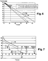
- An area 17 includes instructions for applying to each determined extremum a cycle counting algorithm to determine a thermal cycle to which the system 3 is subjected, and by reading from the table of the figure 4 , produce the consumed lifetimes of the system 3 from the determined cycles. The estimate of this consumed lifetime is performed by reading zone 11 of the memory containing the failure cycle matrix of the figure 3 which is obtained by simulation or feedback. For each determined cycle, the device determines a damage value.
- the cycle counting algorithm is a recursive function. Therefore, for both real-time and RAM requirements, three rotating buffers, one per parameter, are used to store half cycles. In a preferred embodiment, these three buffers can store up to ten consecutive half-cycles. The size of these buffers can be adjusted according to the application.
- the algorithm 16 checks whether the two following conditions are met.
- the first condition is to have at least two half-cycles stored in the buffer.
- the second of the conditions is to have a temperature difference ⁇ T of a new half-cycle higher than that of a previous half-cycle.
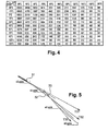
- the temperature difference ⁇ T is the absolute value of the temperature difference of the detected extremes, forming the half-cycle. For example, figure 3 half cycles 18 to 27 are shown.
- the algorithm 16 calculates that the temperature difference of the second half-cycle 19 is less than the temperature difference of the third half-cycle 20. In this case, the second half-cycle 19 is counted as a cycle.
- the extrema 28 and 29 of the second half-cycle are consequently deleted.
- the lifetime consumed is then calculated at each new cycle or residual half-cycle using the relation by reading the visible table 11. figure 4 , extracting for each temperature cycle an average temperature Tmoy and a difference ⁇ T.
- This reading makes it possible to convert each determined cycle into a value of damage equal to the inverse of the number of failure cycles corresponding to a fatigue of this type. It performs a combination of these damage values.
- This accumulation can comprise the taking into account by instructions loaded in an area 30 of the memory 6, figure 1 , a combination of damages of different natures, coming from different types of environment (humidity, pressure, ). This accumulation is transmitted to a comparator. This comparator receives at a second input a previously defined threshold of maximum damage to the system 3.
- the device 1 triggers a warning, making it possible to optimize the maintenance of the system.
- This warning can be triggering an audible and / or visual alarm and / or sending a message to an operator.
- the sending of this message can be transmitted by means of wireless communication protocols, such as those of the UMTS standard or the GSM standard, or Zigbee, etc.
- a life expectancy prognosis for example a number of days of operation before failure.
- a life expectancy prognosis for example a number of days of operation before failure.
- type A visits that every 350 hours of flight (depending on the type of aircraft), it is necessary to know precisely this prognosis to organize at best the preventive replacements.
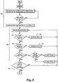
- the points on the diagram of the figure 5 represent, as a function of time, the present time and progressively, the state of health of the system 3.
- the state of health can only decrease, but it decreases more or less according to the rigor of the cycle or the fatigue that justified it.
- the cycle has has been mild, for example between -40 ° C and + 85 ° C, the damage will be low, in any case less than if the cycle was severe, for example between -55 ° C and + 125 ° C.
- the time is on the abscissa and the state of health resulting from the accumulated damages is on the ordinate.
- this correlation coefficient In practice, its absolute value is rarely equal to 1, but it is generally considered that the adjustment is valid as soon as this coefficient has an absolute value greater than ⁇ 3 / 2. In the invention, this correlation coefficient, with a preferred value of 98%, can be used to determine the length of the pieces.
- a new line segment 32 from the new group of measures.
- the lines 31 and 32 are computed over a maximum of n measurements, the n measurements taken into account each time are not necessarily independent.
- the calculations of the linear regression limited to n points are carried out continuously and not only in reaching the n points. Preferably, it is only when the threshold of the correlation coefficient of the main linear regression is exceeded that a reallocation is performed: it is reset with the limited linear regression which has the most points (between n / 2 and n).
- the line 31 gave a (favorable) prognosis T31, while the line 32 gives a less favorable prognosis T32.
- the algorithm of the invention replaces the line 32, and its prognosis T32, by a line 33, and a prognosis T33 even less favorable.
- the prognosis evolves over time, from T31 to T33, and this information is made available to maintenance operators to take them into account for their preventive replacements.
- a five-day prognosis implies the preventive replacement of a system 3 under surveillance if, during a type-A visit, we know that the next type-A visit is in 350 flight hours.
- the figure 6 shows an example of diagnosis and prognosis framed by a pessimistic value and an optimistic value at a time T and their respective T1 and T2 forecasts.
- the adaptive linear regression method developed allows for optimistic and pessimistic environmental variations to be taken into account.
- the optimistic evaluation 34 in the case of temperature measurements, does not take into account the half-cycles eliminated during the treatment, whereas the pessimistic method takes into account all the possible fatigues. In parallel are therefore calculated three classical linear regression.
- the main linear regression starting at T0 and continuing as long as the correlation coefficient is greater than a defined threshold (0.98 for example).
- the other two linear regressions will be calculated on a maximum of n points (200 for example): the first 31 starting at T0, the second 32 after n / 2 measuring points, and so on. Their calculation is updated with each new measurement and reset all n measurements.
- this linear regression immediately takes the value of the linear regression with the most points (between n / 2 and n) among the two linear regressions limited to n points. .
- the main linear regression takes into account recent events and by extrapolation allows a better end-of-life prognosis (a number of days in a preferred example).
- the figure 7 presents an example of the evolution over time of the values T1 and T2 for an electronic system 3 whose end-of-life prognosis is sought.
- the prognosis corresponds to the intersection of the line resulting from the main linear regression with the abscissa axis (durations) for a planned end of life at 100% damage.
- this threshold of 100% can be defined at a lower damage rate according to the knowledge that one has of the system under surveillance as for example to 60%.
- the figure 7 also shows that by a change in exposure conditions, from -40 ° C + 85 ° C to -55 ° C + 125 ° C, the adaptive calculation of the invention makes it possible to replace optimistic and pessimistic curves 34 and 35 by two new curves 36 and 37, giving a prognosis at 65 days much less favorable than the expected 75-day prognosis.
- the adaptive calculation of the invention makes it possible to replace optimistic and pessimistic curves 34 and 35 by two new curves 36 and 37, giving a prognosis at 65 days much less favorable than the expected 75-day prognosis.
- a trend in the present time of the evolution of the consumed lifetime is thus measured, and a corrected prognosis of consumed lifetime is deduced at the present time.
- the figures 8 and 9 present the algorithms used in the invention for calculating the end-of-life prognosis of a system 3 under surveillance.
- the algorithm of the figure 9 is just a duplication of the algorithm of the figure 8 , applied in case optimistic and pessimistic calculations are undertaken.
- the algorithm of the figure 8 has, of conventionally an initialization 38. It also includes the calculations 39 of a main linear regression and two linear regressions limited to n measurements and temporally offset by n / 2 measurements. The limited linear regressions are reset, 40 and 41 each time a new group of n measurement points has been taken into account. Steps 40 and 41 following test steps 42 and 43, respectively, base the computation of the piecewise linear regression.
- a test 44 measures that the end-of-life prognosis is greater than the present time, or a future date of visit type A, B, C or D, to produce replacement information.
- the operation of the algorithm of the figure 8 is done twice: once for optimistic appreciation and once for pessimistic appreciation.
- the memory 6, figure 1 therefore comprises zones 45 to 47 where are stored respectively the functions 38, 39 and 44 of the algorithms of the figure 8 and some figure 9 . It also includes a zone 48 serving as an operating system, management measures, power, and possibly the transmission of results.
Landscapes
- Business, Economics & Management (AREA)
- Human Resources & Organizations (AREA)
- Engineering & Computer Science (AREA)
- Entrepreneurship & Innovation (AREA)
- Economics (AREA)
- Strategic Management (AREA)
- General Physics & Mathematics (AREA)
- Physics & Mathematics (AREA)
- Educational Administration (AREA)
- Development Economics (AREA)
- Operations Research (AREA)
- Quality & Reliability (AREA)
- Tourism & Hospitality (AREA)
- Game Theory and Decision Science (AREA)
- General Business, Economics & Management (AREA)
- Marketing (AREA)
- Theoretical Computer Science (AREA)
- Automation & Control Theory (AREA)
- Testing Of Devices, Machine Parts, Or Other Structures Thereof (AREA)
- Management, Administration, Business Operations System, And Electronic Commerce (AREA)
- Testing Or Calibration Of Command Recording Devices (AREA)
Applications Claiming Priority (2)
| Application Number | Priority Date | Filing Date | Title |
|---|---|---|---|
| FR0852171A FR2929728B1 (fr) | 2008-04-02 | 2008-04-02 | Procede de determination du pronostic de fonctionnement d'un systeme. |
| PCT/EP2009/002378 WO2009121583A1 (fr) | 2008-04-02 | 2009-04-01 | Procede de determination du pronostic de fonctionnement d'un systeme |
Publications (2)
| Publication Number | Publication Date |
|---|---|
| EP2266005A1 EP2266005A1 (fr) | 2010-12-29 |
| EP2266005B1 true EP2266005B1 (fr) | 2019-06-05 |
Family
ID=39768819
Family Applications (1)
| Application Number | Title | Priority Date | Filing Date |
|---|---|---|---|
| EP09728167.9A Active EP2266005B1 (fr) | 2008-04-02 | 2009-04-01 | Procede de determination du pronostic de fonctionnement d'un systeme |
Country Status (8)
| Country | Link |
|---|---|
| US (1) | US20110046996A1 (zh) |
| EP (1) | EP2266005B1 (zh) |
| JP (1) | JP5295352B2 (zh) |
| CN (1) | CN101999101B (zh) |
| BR (1) | BRPI0911371A2 (zh) |
| CA (1) | CA2719130C (zh) |
| FR (1) | FR2929728B1 (zh) |
| WO (1) | WO2009121583A1 (zh) |
Families Citing this family (11)
| Publication number | Priority date | Publication date | Assignee | Title |
|---|---|---|---|---|
| DE102010047305A1 (de) * | 2010-10-01 | 2012-04-05 | Ika-Werke Gmbh & Co. Kg | Misch-, Rühr- oder Dispergierverfahren und Vorrichtung hierfür |
| US8909453B2 (en) | 2012-01-12 | 2014-12-09 | Bell-Helicopter Textron Inc. | System and method of measuring and monitoring torque in a rotorcraft drive system |
| WO2015023201A2 (en) * | 2013-06-19 | 2015-02-19 | Continuware Corporation | Method and system for determining hardware life expectancy and failure prevention |
| US10496787B2 (en) | 2013-07-02 | 2019-12-03 | Bell Helicopter Textron Inc. | System and method of rotorcraft usage monitoring |
| US20160306555A1 (en) * | 2013-12-20 | 2016-10-20 | Sinchan Banerjee | Storage capacity regression |
| CN105469980A (zh) * | 2014-09-26 | 2016-04-06 | 西门子公司 | 电容器模块、电路布置及运行方法 |
| US9568912B2 (en) * | 2015-06-15 | 2017-02-14 | Honeywell International Inc. | Aircraft prognostic systems and methods for determining adaptive time between overhaul for line replaceable units |
| CN108268076B (zh) * | 2018-01-23 | 2020-12-22 | 江苏省兴安科技发展有限公司 | 一种基于大数据的机房运行安全评估系统 |
| JP7430024B2 (ja) * | 2020-07-16 | 2024-02-09 | ベンテック ライフ システムズ, インコーポレイテッド | ガスを濃縮するためのシステムおよび方法 |
| EP4181993A1 (en) | 2020-07-16 | 2023-05-24 | Invacare Corporation | System and method for concentrating gas |
| US11952142B2 (en) * | 2021-05-10 | 2024-04-09 | Honeywell International Inc. | Methods and systems for depicting avionics data anomalies |
Family Cites Families (17)
| Publication number | Priority date | Publication date | Assignee | Title |
|---|---|---|---|---|
| US4866714A (en) * | 1987-10-15 | 1989-09-12 | Westinghouse Electric Corp. | Personal computer-based dynamic burn-in system |
| JP2738732B2 (ja) * | 1988-09-16 | 1998-04-08 | 株式会社日立製作所 | 劣化度予測装置および方法 |
| JP3201809B2 (ja) * | 1992-01-30 | 2001-08-27 | 三菱電機株式会社 | パルスレーザ装置 |
| JPH0714948A (ja) * | 1993-06-15 | 1995-01-17 | Hitachi Ltd | パワー半導体モジュール |
| DE19708617C2 (de) * | 1997-03-03 | 1999-02-04 | Siemens Ag | Chipkartenmodul und Verfahren zu seiner Herstellung sowie diesen umfassende Chipkarte |
| US6977517B2 (en) * | 2002-05-20 | 2005-12-20 | Finisar Corporation | Laser production and product qualification via accelerated life testing based on statistical modeling |
| JP2004045343A (ja) * | 2002-07-15 | 2004-02-12 | Toshiba Corp | はんだ接合部の寿命診断方法及び装置 |
| FR2844902B1 (fr) | 2002-09-19 | 2013-09-13 | Eads Ccr Groupement D Interet Economique | Dispositif et procede d'enregistrement de donnees environnementales |
| DE10328721A1 (de) * | 2003-06-25 | 2005-01-13 | Robert Bosch Gmbh | Verfahren zur Vorhersage einer Restlebensdauer eines elektrischen Energiespeichers |
| JP4244194B2 (ja) * | 2004-02-17 | 2009-03-25 | 日本電信電話株式会社 | ニッケル水素蓄電池の寿命予測法 |
| JP4115405B2 (ja) * | 2004-02-27 | 2008-07-09 | 三菱重工業株式会社 | 水中構造物の劣化速度予測方法及び劣化診断システム |
| JP4185906B2 (ja) * | 2004-12-01 | 2008-11-26 | キヤノン株式会社 | 画像耐ガス性試験方法 |
| US20060271255A1 (en) | 2004-12-30 | 2006-11-30 | Teradyne, Inc. | System and method for vehicle diagnostics and prognostics |
| FR2896875B1 (fr) | 2006-01-30 | 2008-04-25 | Eads Europ Aeronautic Defence | Dispositif et procede de surveillance d'une grandeur environnementale en temps reel |
| US7514941B2 (en) * | 2006-03-15 | 2009-04-07 | Raytheon Company | Method and apparatus for predicting the reliability of electronic systems |
| JP5233198B2 (ja) * | 2007-08-06 | 2013-07-10 | 富士電機株式会社 | 半導体装置 |
| US8494810B2 (en) * | 2009-06-05 | 2013-07-23 | Jentek Sensors, Inc. | Component adaptive life management |
-
2008
- 2008-04-02 FR FR0852171A patent/FR2929728B1/fr not_active Expired - Fee Related
-
2009
- 2009-04-01 JP JP2011502289A patent/JP5295352B2/ja not_active Expired - Fee Related
- 2009-04-01 EP EP09728167.9A patent/EP2266005B1/fr active Active
- 2009-04-01 BR BRPI0911371A patent/BRPI0911371A2/pt not_active Application Discontinuation
- 2009-04-01 US US12/935,665 patent/US20110046996A1/en not_active Abandoned
- 2009-04-01 WO PCT/EP2009/002378 patent/WO2009121583A1/fr active Application Filing
- 2009-04-01 CN CN200980113066.9A patent/CN101999101B/zh not_active Expired - Fee Related
- 2009-04-01 CA CA2719130A patent/CA2719130C/fr not_active Expired - Fee Related
Non-Patent Citations (1)
| Title |
|---|
| None * |
Also Published As
| Publication number | Publication date |
|---|---|
| FR2929728B1 (fr) | 2011-01-14 |
| JP5295352B2 (ja) | 2013-09-18 |
| CA2719130C (fr) | 2015-10-06 |
| CN101999101B (zh) | 2015-10-14 |
| BRPI0911371A2 (pt) | 2015-12-29 |
| CA2719130A1 (fr) | 2009-10-08 |
| JP2011520170A (ja) | 2011-07-14 |
| EP2266005A1 (fr) | 2010-12-29 |
| WO2009121583A1 (fr) | 2009-10-08 |
| FR2929728A1 (fr) | 2009-10-09 |
| CN101999101A (zh) | 2011-03-30 |
| US20110046996A1 (en) | 2011-02-24 |
Similar Documents
| Publication | Publication Date | Title |
|---|---|---|
| EP2266005B1 (fr) | Procede de determination du pronostic de fonctionnement d'un systeme | |
| EP0573357B1 (fr) | Procédé de diagnostic d'un processus évolutif | |
| EP3039497B1 (fr) | Surveillance d'un moteur d'aéronef pour anticiper les opérations de maintenance | |
| EP2627982B1 (fr) | Système de surveillance d'un banc d'essai de moteur d'aeronef | |
| EP3044601B1 (fr) | Procede, dispositif et systeme d'estimation de l'etat de charge d'une batterie | |
| FR2970358A1 (fr) | Pronostic de duree avant maintenance par fusion entre modelisation et simulation, pour equipements electroniques embarques dans un aeronef | |
| FR2759794A1 (fr) | Systeme et procede de surveillance de production d'une presse | |
| FR2909792A1 (fr) | Systeme de maintenance centralisee d'equipements electroniques embarques | |
| KR102574084B1 (ko) | 배터리 관리 장치 및 방법 | |
| FR2939928A1 (fr) | Standardisation de donnees utilisees pour la surveillance d'un moteur d'aeronef | |
| EP2151791A1 (fr) | Procédé amélioré pour organiser la maintenance d'aeronefs | |
| WO2016097633A1 (fr) | Procédé de transmission de données issues d'un capteur | |
| FR3066844A1 (fr) | Procede de prevision de la survenue d'une defaillance sur un appareil dans le temps | |
| EP3842185A1 (fr) | Procédé d'aide à la maintenance d'un outil industriel, outil et système correspondants, et programme mettant en uvre le procédé | |
| FR3035232A1 (fr) | Systeme de surveillance de l'etat de sante d'un moteur et procede de configuration associe | |
| EP1979717A2 (fr) | Dispositif et procede de surveillance d'une grandeur environnementale en temps reel | |
| CN116415126A (zh) | 用于造纸机的刮刀的异常检测的方法、装置和计算设备 | |
| CA2789296A1 (fr) | Systemes permettant l'acquisition et le traitement de donnees issues de mesures physiques, procede de fabrication des dispositifs et utilisations des systemes pour tester les performances d'un appareillage | |
| EP1067392B1 (fr) | Procédé de tests de composants électroniques | |
| CA3121061A1 (fr) | Procede et systeme de controle d'un niveau d'endommagement d'au moins une piece d'aeronef, aeronef associe | |
| EP3343375B1 (fr) | Procédé et système de surveillance de traitements par lots d'applications exécutées dans une infrastructure informatique | |
| CN114450696A (zh) | 数据同化框架中的物理传感器的集成 | |
| EP3182287B1 (fr) | Procede et systeme de controle de la fiabilite d'au moins un equipement electronique installe dans un aeronef | |
| US11513159B1 (en) | Systems for analysis of vehicle electrical system performance | |
| EP1401231B1 (fr) | Dispositif et procédé d'enregistrement de données environnementales |
Legal Events
| Date | Code | Title | Description |
|---|---|---|---|
| PUAI | Public reference made under article 153(3) epc to a published international application that has entered the european phase |
Free format text: ORIGINAL CODE: 0009012 |
|
| 17P | Request for examination filed |
Effective date: 20100929 |
|
| AK | Designated contracting states |
Kind code of ref document: A1 Designated state(s): AT BE BG CH CY CZ DE DK EE ES FI FR GB GR HR HU IE IS IT LI LT LU LV MC MK MT NL NO PL PT RO SE SI SK TR |
|
| AX | Request for extension of the european patent |
Extension state: AL BA RS |
|
| DAX | Request for extension of the european patent (deleted) | ||
| RAP1 | Party data changed (applicant data changed or rights of an application transferred) |
Owner name: AIRBUS (SAS) |
|
| REG | Reference to a national code |
Ref country code: DE Ref legal event code: R079 Ref document number: 602009058613 Country of ref document: DE Free format text: PREVIOUS MAIN CLASS: G05B0023020000 Ipc: G06Q0010060000 |
|
| RIC1 | Information provided on ipc code assigned before grant |
Ipc: G06Q 10/06 20120101AFI20180926BHEP Ipc: G06F 11/30 20060101ALI20180926BHEP Ipc: G05B 23/02 20060101ALI20180926BHEP |
|
| GRAP | Despatch of communication of intention to grant a patent |
Free format text: ORIGINAL CODE: EPIDOSNIGR1 |
|
| STAA | Information on the status of an ep patent application or granted ep patent |
Free format text: STATUS: GRANT OF PATENT IS INTENDED |
|
| INTG | Intention to grant announced |
Effective date: 20190104 |
|
| RIN1 | Information on inventor provided before grant (corrected) |
Inventor name: FOUCHER, BRUNO Inventor name: ROUET, VINCENT Inventor name: MOREAU, KATELL |
|
| RIC1 | Information provided on ipc code assigned before grant |
Ipc: G06Q 10/06 20120101AFI20180926BHEP Ipc: G06F 11/30 20060101ALI20180926BHEP Ipc: G05B 23/02 20060101ALI20180926BHEP |
|
| GRAS | Grant fee paid |
Free format text: ORIGINAL CODE: EPIDOSNIGR3 |
|
| GRAA | (expected) grant |
Free format text: ORIGINAL CODE: 0009210 |
|
| STAA | Information on the status of an ep patent application or granted ep patent |
Free format text: STATUS: THE PATENT HAS BEEN GRANTED |
|
| AK | Designated contracting states |
Kind code of ref document: B1 Designated state(s): AT BE BG CH CY CZ DE DK EE ES FI FR GB GR HR HU IE IS IT LI LT LU LV MC MK MT NL NO PL PT RO SE SI SK TR |
|
| REG | Reference to a national code |
Ref country code: GB Ref legal event code: FG4D Free format text: NOT ENGLISH |
|
| REG | Reference to a national code |
Ref country code: CH Ref legal event code: EP |
|
| REG | Reference to a national code |
Ref country code: AT Ref legal event code: REF Ref document number: 1140747 Country of ref document: AT Kind code of ref document: T Effective date: 20190615 |
|
| REG | Reference to a national code |
Ref country code: IE Ref legal event code: FG4D Free format text: LANGUAGE OF EP DOCUMENT: FRENCH |
|
| REG | Reference to a national code |
Ref country code: DE Ref legal event code: R096 Ref document number: 602009058613 Country of ref document: DE |
|
| REG | Reference to a national code |
Ref country code: NL Ref legal event code: MP Effective date: 20190605 |
|
| REG | Reference to a national code |
Ref country code: LT Ref legal event code: MG4D |
|
| PG25 | Lapsed in a contracting state [announced via postgrant information from national office to epo] |
Ref country code: FI Free format text: LAPSE BECAUSE OF FAILURE TO SUBMIT A TRANSLATION OF THE DESCRIPTION OR TO PAY THE FEE WITHIN THE PRESCRIBED TIME-LIMIT Effective date: 20190605 Ref country code: SE Free format text: LAPSE BECAUSE OF FAILURE TO SUBMIT A TRANSLATION OF THE DESCRIPTION OR TO PAY THE FEE WITHIN THE PRESCRIBED TIME-LIMIT Effective date: 20190605 Ref country code: ES Free format text: LAPSE BECAUSE OF FAILURE TO SUBMIT A TRANSLATION OF THE DESCRIPTION OR TO PAY THE FEE WITHIN THE PRESCRIBED TIME-LIMIT Effective date: 20190605 Ref country code: LT Free format text: LAPSE BECAUSE OF FAILURE TO SUBMIT A TRANSLATION OF THE DESCRIPTION OR TO PAY THE FEE WITHIN THE PRESCRIBED TIME-LIMIT Effective date: 20190605 Ref country code: HR Free format text: LAPSE BECAUSE OF FAILURE TO SUBMIT A TRANSLATION OF THE DESCRIPTION OR TO PAY THE FEE WITHIN THE PRESCRIBED TIME-LIMIT Effective date: 20190605 Ref country code: NO Free format text: LAPSE BECAUSE OF FAILURE TO SUBMIT A TRANSLATION OF THE DESCRIPTION OR TO PAY THE FEE WITHIN THE PRESCRIBED TIME-LIMIT Effective date: 20190905 |
|
| PG25 | Lapsed in a contracting state [announced via postgrant information from national office to epo] |
Ref country code: GR Free format text: LAPSE BECAUSE OF FAILURE TO SUBMIT A TRANSLATION OF THE DESCRIPTION OR TO PAY THE FEE WITHIN THE PRESCRIBED TIME-LIMIT Effective date: 20190906 Ref country code: LV Free format text: LAPSE BECAUSE OF FAILURE TO SUBMIT A TRANSLATION OF THE DESCRIPTION OR TO PAY THE FEE WITHIN THE PRESCRIBED TIME-LIMIT Effective date: 20190605 Ref country code: BG Free format text: LAPSE BECAUSE OF FAILURE TO SUBMIT A TRANSLATION OF THE DESCRIPTION OR TO PAY THE FEE WITHIN THE PRESCRIBED TIME-LIMIT Effective date: 20190905 |
|
| REG | Reference to a national code |
Ref country code: AT Ref legal event code: MK05 Ref document number: 1140747 Country of ref document: AT Kind code of ref document: T Effective date: 20190605 |
|
| PG25 | Lapsed in a contracting state [announced via postgrant information from national office to epo] |
Ref country code: CZ Free format text: LAPSE BECAUSE OF FAILURE TO SUBMIT A TRANSLATION OF THE DESCRIPTION OR TO PAY THE FEE WITHIN THE PRESCRIBED TIME-LIMIT Effective date: 20190605 Ref country code: PT Free format text: LAPSE BECAUSE OF FAILURE TO SUBMIT A TRANSLATION OF THE DESCRIPTION OR TO PAY THE FEE WITHIN THE PRESCRIBED TIME-LIMIT Effective date: 20191007 Ref country code: NL Free format text: LAPSE BECAUSE OF FAILURE TO SUBMIT A TRANSLATION OF THE DESCRIPTION OR TO PAY THE FEE WITHIN THE PRESCRIBED TIME-LIMIT Effective date: 20190605 Ref country code: RO Free format text: LAPSE BECAUSE OF FAILURE TO SUBMIT A TRANSLATION OF THE DESCRIPTION OR TO PAY THE FEE WITHIN THE PRESCRIBED TIME-LIMIT Effective date: 20190605 Ref country code: AT Free format text: LAPSE BECAUSE OF FAILURE TO SUBMIT A TRANSLATION OF THE DESCRIPTION OR TO PAY THE FEE WITHIN THE PRESCRIBED TIME-LIMIT Effective date: 20190605 Ref country code: EE Free format text: LAPSE BECAUSE OF FAILURE TO SUBMIT A TRANSLATION OF THE DESCRIPTION OR TO PAY THE FEE WITHIN THE PRESCRIBED TIME-LIMIT Effective date: 20190605 Ref country code: SK Free format text: LAPSE BECAUSE OF FAILURE TO SUBMIT A TRANSLATION OF THE DESCRIPTION OR TO PAY THE FEE WITHIN THE PRESCRIBED TIME-LIMIT Effective date: 20190605 |
|
| PG25 | Lapsed in a contracting state [announced via postgrant information from national office to epo] |
Ref country code: IT Free format text: LAPSE BECAUSE OF FAILURE TO SUBMIT A TRANSLATION OF THE DESCRIPTION OR TO PAY THE FEE WITHIN THE PRESCRIBED TIME-LIMIT Effective date: 20190605 Ref country code: IS Free format text: LAPSE BECAUSE OF FAILURE TO SUBMIT A TRANSLATION OF THE DESCRIPTION OR TO PAY THE FEE WITHIN THE PRESCRIBED TIME-LIMIT Effective date: 20191005 |
|
| REG | Reference to a national code |
Ref country code: DE Ref legal event code: R097 Ref document number: 602009058613 Country of ref document: DE |
|
| PG25 | Lapsed in a contracting state [announced via postgrant information from national office to epo] |
Ref country code: TR Free format text: LAPSE BECAUSE OF FAILURE TO SUBMIT A TRANSLATION OF THE DESCRIPTION OR TO PAY THE FEE WITHIN THE PRESCRIBED TIME-LIMIT Effective date: 20190605 |
|
| PLBE | No opposition filed within time limit |
Free format text: ORIGINAL CODE: 0009261 |
|
| STAA | Information on the status of an ep patent application or granted ep patent |
Free format text: STATUS: NO OPPOSITION FILED WITHIN TIME LIMIT |
|
| PG25 | Lapsed in a contracting state [announced via postgrant information from national office to epo] |
Ref country code: DK Free format text: LAPSE BECAUSE OF FAILURE TO SUBMIT A TRANSLATION OF THE DESCRIPTION OR TO PAY THE FEE WITHIN THE PRESCRIBED TIME-LIMIT Effective date: 20190605 Ref country code: PL Free format text: LAPSE BECAUSE OF FAILURE TO SUBMIT A TRANSLATION OF THE DESCRIPTION OR TO PAY THE FEE WITHIN THE PRESCRIBED TIME-LIMIT Effective date: 20190605 |
|
| 26N | No opposition filed |
Effective date: 20200306 |
|
| PG25 | Lapsed in a contracting state [announced via postgrant information from national office to epo] |
Ref country code: SI Free format text: LAPSE BECAUSE OF FAILURE TO SUBMIT A TRANSLATION OF THE DESCRIPTION OR TO PAY THE FEE WITHIN THE PRESCRIBED TIME-LIMIT Effective date: 20190605 |
|
| PGFP | Annual fee paid to national office [announced via postgrant information from national office to epo] |
Ref country code: DE Payment date: 20200420 Year of fee payment: 12 Ref country code: FR Payment date: 20200420 Year of fee payment: 12 |
|
| PGFP | Annual fee paid to national office [announced via postgrant information from national office to epo] |
Ref country code: GB Payment date: 20200427 Year of fee payment: 12 |
|
| PG25 | Lapsed in a contracting state [announced via postgrant information from national office to epo] |
Ref country code: MC Free format text: LAPSE BECAUSE OF FAILURE TO SUBMIT A TRANSLATION OF THE DESCRIPTION OR TO PAY THE FEE WITHIN THE PRESCRIBED TIME-LIMIT Effective date: 20190605 |
|
| REG | Reference to a national code |
Ref country code: CH Ref legal event code: PL |
|
| PG25 | Lapsed in a contracting state [announced via postgrant information from national office to epo] |
Ref country code: LU Free format text: LAPSE BECAUSE OF NON-PAYMENT OF DUE FEES Effective date: 20200401 Ref country code: CH Free format text: LAPSE BECAUSE OF NON-PAYMENT OF DUE FEES Effective date: 20200430 Ref country code: LI Free format text: LAPSE BECAUSE OF NON-PAYMENT OF DUE FEES Effective date: 20200430 |
|
| REG | Reference to a national code |
Ref country code: BE Ref legal event code: MM Effective date: 20200430 |
|
| PG25 | Lapsed in a contracting state [announced via postgrant information from national office to epo] |
Ref country code: BE Free format text: LAPSE BECAUSE OF NON-PAYMENT OF DUE FEES Effective date: 20200430 |
|
| PG25 | Lapsed in a contracting state [announced via postgrant information from national office to epo] |
Ref country code: IE Free format text: LAPSE BECAUSE OF NON-PAYMENT OF DUE FEES Effective date: 20200401 |
|
| REG | Reference to a national code |
Ref country code: DE Ref legal event code: R119 Ref document number: 602009058613 Country of ref document: DE |
|
| GBPC | Gb: european patent ceased through non-payment of renewal fee |
Effective date: 20210401 |
|
| PG25 | Lapsed in a contracting state [announced via postgrant information from national office to epo] |
Ref country code: GB Free format text: LAPSE BECAUSE OF NON-PAYMENT OF DUE FEES Effective date: 20210401 Ref country code: FR Free format text: LAPSE BECAUSE OF NON-PAYMENT OF DUE FEES Effective date: 20210430 Ref country code: DE Free format text: LAPSE BECAUSE OF NON-PAYMENT OF DUE FEES Effective date: 20211103 |
|
| PG25 | Lapsed in a contracting state [announced via postgrant information from national office to epo] |
Ref country code: MT Free format text: LAPSE BECAUSE OF FAILURE TO SUBMIT A TRANSLATION OF THE DESCRIPTION OR TO PAY THE FEE WITHIN THE PRESCRIBED TIME-LIMIT Effective date: 20190605 Ref country code: CY Free format text: LAPSE BECAUSE OF FAILURE TO SUBMIT A TRANSLATION OF THE DESCRIPTION OR TO PAY THE FEE WITHIN THE PRESCRIBED TIME-LIMIT Effective date: 20190605 |
|
| PG25 | Lapsed in a contracting state [announced via postgrant information from national office to epo] |
Ref country code: MK Free format text: LAPSE BECAUSE OF FAILURE TO SUBMIT A TRANSLATION OF THE DESCRIPTION OR TO PAY THE FEE WITHIN THE PRESCRIBED TIME-LIMIT Effective date: 20190605 |