EP2265477B1 - Wiper blade and windshield wiper system having such a wiper blade - Google Patents
Wiper blade and windshield wiper system having such a wiper blade Download PDFInfo
- Publication number
- EP2265477B1 EP2265477B1 EP09734764.5A EP09734764A EP2265477B1 EP 2265477 B1 EP2265477 B1 EP 2265477B1 EP 09734764 A EP09734764 A EP 09734764A EP 2265477 B1 EP2265477 B1 EP 2265477B1
- Authority
- EP
- European Patent Office
- Prior art keywords
- wiper blade
- heating element
- heating
- wiper
- spraying duct
- Prior art date
- Legal status (The legal status is an assumption and is not a legal conclusion. Google has not performed a legal analysis and makes no representation as to the accuracy of the status listed.)
- Active
Links
- 238000010438 heat treatment Methods 0.000 claims description 142
- 238000004140 cleaning Methods 0.000 claims description 32
- 238000005406 washing Methods 0.000 claims description 24
- 239000007788 liquid Substances 0.000 claims description 21
- 238000005507 spraying Methods 0.000 claims description 14
- 238000005485 electric heating Methods 0.000 claims description 4
- 239000004033 plastic Substances 0.000 claims description 4
- 239000007921 spray Substances 0.000 description 44
- 238000002347 injection Methods 0.000 description 23
- 239000007924 injection Substances 0.000 description 23
- 230000033228 biological regulation Effects 0.000 description 5
- 239000012530 fluid Substances 0.000 description 4
- 238000007789 sealing Methods 0.000 description 3
- 230000004913 activation Effects 0.000 description 2
- 239000000654 additive Substances 0.000 description 2
- 230000002528 anti-freeze Effects 0.000 description 2
- 230000007423 decrease Effects 0.000 description 2
- 230000001419 dependent effect Effects 0.000 description 2
- 230000000694 effects Effects 0.000 description 2
- XLYOFNOQVPJJNP-UHFFFAOYSA-N water Substances O XLYOFNOQVPJJNP-UHFFFAOYSA-N 0.000 description 2
- 229910000639 Spring steel Inorganic materials 0.000 description 1
- 230000000712 assembly Effects 0.000 description 1
- 238000000429 assembly Methods 0.000 description 1
- 239000004020 conductor Substances 0.000 description 1
- 238000010276 construction Methods 0.000 description 1
- 230000007797 corrosion Effects 0.000 description 1
- 238000005260 corrosion Methods 0.000 description 1
- 230000003247 decreasing effect Effects 0.000 description 1
- 230000003111 delayed effect Effects 0.000 description 1
- 238000011161 development Methods 0.000 description 1
- 230000018109 developmental process Effects 0.000 description 1
- 239000013013 elastic material Substances 0.000 description 1
- 238000010292 electrical insulation Methods 0.000 description 1
- 230000007613 environmental effect Effects 0.000 description 1
- 238000009434 installation Methods 0.000 description 1
- 238000005259 measurement Methods 0.000 description 1
- 229910001092 metal group alloy Inorganic materials 0.000 description 1
- YNBADRVTZLEFNH-UHFFFAOYSA-N methyl nicotinate Chemical compound COC(=O)C1=CC=CN=C1 YNBADRVTZLEFNH-UHFFFAOYSA-N 0.000 description 1
- 238000012986 modification Methods 0.000 description 1
- 230000004048 modification Effects 0.000 description 1
- 230000001105 regulatory effect Effects 0.000 description 1
Images


Classifications
-
- B—PERFORMING OPERATIONS; TRANSPORTING
- B60—VEHICLES IN GENERAL
- B60S—SERVICING, CLEANING, REPAIRING, SUPPORTING, LIFTING, OR MANOEUVRING OF VEHICLES, NOT OTHERWISE PROVIDED FOR
- B60S1/00—Cleaning of vehicles
- B60S1/02—Cleaning windscreens, windows or optical devices
- B60S1/04—Wipers or the like, e.g. scrapers
- B60S1/32—Wipers or the like, e.g. scrapers characterised by constructional features of wiper blade arms or blades
- B60S1/38—Wiper blades
- B60S1/3848—Flat-type wiper blade, i.e. without harness
- B60S1/3874—Flat-type wiper blade, i.e. without harness with a reinforcing vertebra
- B60S1/3875—Flat-type wiper blade, i.e. without harness with a reinforcing vertebra rectangular section
- B60S1/3881—Flat-type wiper blade, i.e. without harness with a reinforcing vertebra rectangular section in additional element, e.g. spoiler
-
- B—PERFORMING OPERATIONS; TRANSPORTING
- B60—VEHICLES IN GENERAL
- B60S—SERVICING, CLEANING, REPAIRING, SUPPORTING, LIFTING, OR MANOEUVRING OF VEHICLES, NOT OTHERWISE PROVIDED FOR
- B60S1/00—Cleaning of vehicles
- B60S1/02—Cleaning windscreens, windows or optical devices
- B60S1/04—Wipers or the like, e.g. scrapers
- B60S1/32—Wipers or the like, e.g. scrapers characterised by constructional features of wiper blade arms or blades
- B60S1/38—Wiper blades
- B60S1/3803—Wiper blades heated wiper blades
- B60S1/3805—Wiper blades heated wiper blades electrically
-
- B—PERFORMING OPERATIONS; TRANSPORTING
- B60—VEHICLES IN GENERAL
- B60S—SERVICING, CLEANING, REPAIRING, SUPPORTING, LIFTING, OR MANOEUVRING OF VEHICLES, NOT OTHERWISE PROVIDED FOR
- B60S1/00—Cleaning of vehicles
- B60S1/02—Cleaning windscreens, windows or optical devices
- B60S1/46—Cleaning windscreens, windows or optical devices using liquid; Windscreen washers
- B60S1/48—Liquid supply therefor
- B60S1/52—Arrangement of nozzles; Liquid spreading means
- B60S1/522—Arrangement of nozzles; Liquid spreading means moving liquid spreading means, e.g. arranged in wiper arms
- B60S1/524—Arrangement of nozzles; Liquid spreading means moving liquid spreading means, e.g. arranged in wiper arms arranged in wiper blades
-
- B—PERFORMING OPERATIONS; TRANSPORTING
- B60—VEHICLES IN GENERAL
- B60S—SERVICING, CLEANING, REPAIRING, SUPPORTING, LIFTING, OR MANOEUVRING OF VEHICLES, NOT OTHERWISE PROVIDED FOR
- B60S1/00—Cleaning of vehicles
- B60S1/02—Cleaning windscreens, windows or optical devices
- B60S1/04—Wipers or the like, e.g. scrapers
- B60S1/32—Wipers or the like, e.g. scrapers characterised by constructional features of wiper blade arms or blades
- B60S1/38—Wiper blades
- B60S1/3848—Flat-type wiper blade, i.e. without harness
- B60S1/3886—End caps
- B60S1/3887—Mounting of end caps
Definitions
- the invention relates to a wiper blade for cleaning windows on vehicles according to the preamble of claim 1 and a windshield wiper system using a wiper blade according to the invention.
- a wiper blade according to the preamble of claim 1 is known from US 5,426,814 known.
- the known wiper blade has a heating device in the form of a heating wire according to Fig. 6 the mentioned document is arranged as a coiled wire within a spray channel for a washing liquid.
- the electrical connection of the heating wire takes place at the two end faces of the front channel.
- the wire is connected at one end to the electrical ground of the wiper.
- the object of the invention is to develop a wiper blade for cleaning windows on vehicles according to the preamble of claim 1 such that a simplified electrical contact is made possible.
- a wiper blade with the features of claim 1, characterized in that the at least one injection channel is formed on a longitudinal side of the wiper blade that forms at least one heating element within the wiper blade at least one heating loop, and that the ends of at least one within the wiper blade formed at a wiper blade end or between the wiper blade ends, for example in the middle or approximately in the middle of the wiper blade, are provided.
- wiper blades are known for use in windshield wiper systems for cleaning windows in various designs.
- flat wiper blades ie wiper blades formed as flat wiper blades, which essentially consist of a wiper blade body extending over the entire length of the respective wiper blade with at least one squeegee blade forming at least one wiper lip and at least one spring rail. It is also known to form such flat wiper blades with spray channels, each extending on a wiper blade longitudinal side and having a plurality of nozzle openings, via the during the wiping operation of the spray channels from a vehicle-side supply unit under pressure supplied washing and cleaning liquid (usually water ggs. with cleaning and / or antifreeze additives) can be applied to the relevant vehicle window ( DE 103 23 998 A1 . DE 100 00 381 A1 ).
- washing and cleaning liquid usually water ggs. with cleaning and / or antifreeze additives
- EP 0 667 267 A1 mounted on the vehicle body spray nozzles a windshield washer and the supply lines leading to these spray nozzles by heating within these supply lines and the spray nozzles and formed by a heating element or heating wire heating element to prevent icing of the nozzles and the supply lines.
- the at least one heating element within the wiper blade is provided so that it extends at least a partial length within the at least one spray channel, so that with the heating element directly heating this spray channel or, guided in the spray channel washing and cleaning liquid and thus also an immediate heating of the at least one nozzle opening of the spray channel he follows.
- the at least one injection channel is provided with a plurality of nozzle openings.
- the wiper blade For the assembly of the at least one heating element, which is preferably formed by a heating conductor or heating wire, no additional measures are basically required on the wiper blade, ie for laying the heating element of the at least one injection channel is used, which extends along a wiper blade longitudinal side. If the wiper blade has a plurality of injection channels, for example at least two injection channels, each of which is located on a longitudinal side of the wiper blade, then extends the heating loop formed by the at least one heating element through all spray channels, and thereby, for example, so that the at least one heating element is housed within the wiper blade exclusively in the spray channels, except at most of partial lengths at the two wiper blade ends.
- the at least one heating element forms at least one additional heating element section which extends outside the wiper blade and serves to heat at least a partial length of a supply line for the washing and cleaning fluid, which (partial length) is in an area of the vehicle is in danger of icing up the supply line.
- This heating element section serving for heating the supply line is also preferably arranged in the interior or lumen of the at least one supply line.
- the washing and cleaning liquid is heated at least in the at least one injection channel of the wiper blade so that effective heating of the washing and cleaning liquid flowing around the heating element is achieved with reduced demand for electrical energy.
- the invention not only icing of the at least one wiper blade spray channel and the nozzle or nozzle openings therein and the supply line is effectively prevented, but by the heating of the washing and cleaning liquid and the cleaning effect is substantially improved.
- the at least one heating element is automatically controlled or regulated as a function of environmental parameters and / or as a function of operating parameters of the vehicle.
- a control or regulation is then, for example, designed such that the switching on of the at least one heating element, for example when the wiper system is activated, takes place automatically as a function of the outside temperature, specifically if a predetermined threshold value, for example a Outside temperature of about 5 ° C is exceeded.
- the control or regulation of the at least one heating element is further preferably carried out so that the heating element is initially operated after switching on for a short period of time with an increased heating power to quickly eliminate any existing icing or to heat the washing and cleaning fluid quickly and as delay as possible to produce the operability of the windscreen washer system.
- the operating parameters used for the control or regulation of the at least one heating element are, for example, the traveling speed of the vehicle and / or the wiper frequency, i. the frequency or speed at which the pivoting of the at least one wiper arm of the windshield wiper system takes place.
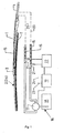
- FIG. 1 - 4 1 is the wiper arm of a windscreen wiper system for vehicles, for example for road vehicles, not shown in detail, and 2 the wiper blade fastened at one end of the wiper arm 1 by means of an adapter 3.
- the wiper arm 1 In the assembled state, the wiper arm 1 is fixed at its end remote from the adapter 3 and formed by a bearing piece 4 on a non-illustrated wiper shaft of a windshield wiper drive, also not shown.
- the wiper blade 2 is in each case designed as a flat wiper blade and consists according to the FIG. 2 from a profile or strip-shaped, for example made of plastic wiper blade body 5, which encloses a profile section 5.1 made of spring steel flat spring rail 6 and on the underside in a C-shaped recess of the profile section 5.2 of a professional from a rubber-elastic material, for example consisting of an elastomeric plastic or rubber squeegee 7 is exchangeably fixed, in such a way that this squeegee 7, in particular with a tipping web 7.1 and the wiper lip 7.2 forming profile section projects beyond the underside of the wiper blade body 5.
- a profile or strip-shaped for example made of plastic wiper blade body 5
- a wiper blade profile 8 is fixed, which is formed on the upper side of the wiper blade as a spoiler and on both sides of the profile section 5.2 respectively an injection channel 9 and 10 forms for a washing and cleaning liquid ggs usually from water. with cleaning and antifreeze additives.
- Each injection channel 9 and 10 which extends along each one longitudinal side of the wiper blade 2, has a plurality of injection or nozzle openings 11, for the purpose of applying the washing and cleaning liquid to those in the FIG. 2 schematically with 12 indicated vehicle window against which the wiper lip 7.2 rests at least during the wiping operation.
- the wiper blade body 5 or the profile forming this body, the spring rail 6 and also the wiper blade element 8 with the two spray channels 9 and 10 each extend over the entire length of the wiper blade. At both ends of the injection channels 9 and 10 are each by a sealing plug 13 (FIG. FIG. 3 ) tightly closed. Furthermore, a cap 14 is attached to each wiper blade end, which cover the local ends of the wiper blade body 5 of the wiper blade element 8 and the spring rail 6 and connects these elements together. In the illustrated embodiment, the respective cap 14 is secured by latching or other suitable means to the over the wiper blade element 8 protruding end of the spring rail 6.
- hose lines 15 For supplying the washing and cleaning liquid are two hose lines 15, which extend partially along the wiper arm 1 and each with an output of a supply unit 16, i. are connected to an output of a pump 17 of this supply unit, which in addition to the driven by an electric motor pump 17 u.a. also has a washing and cleaning fluid receiving tank 18. 19 with a control device is called, which is turned on windshield wiper system and also powered windscreen washer u.a. the pump 17 controls such that the washing and cleaning liquid is supplied to the spray channels 9 and 10 via the hose lines 15 with the required pressure, so that these washing and cleaning liquid can be applied to the vehicle window 12 via the nozzle openings 11.
- a special feature is that the wiper blade 2 or its injection channels 9 and 10 and the associated nozzles 11, but also the hose lines 15, the latter at least over a partial length, are electrically heated, by a heating element, which in the Figures 1 - 4 denoted by 20.
- This heating element 20 is in the illustrated embodiment of a heating wire, for example, has a round cross-section and is provided with a temperature-resistant and suitable for electrical insulation and corrosion protection sheath, for example, with a sheath made of plastic.
- the heating wire are, for example, such metal alloys that are commonly used for electrical heating elements.
- the heating wire of PTC with the advantage that the electrical resistance of this heating wire increases with increasing temperature, whereby the heating power decreases with increasing temperature during operation of the heating element 20 with a predetermined voltage, thereby, inter alia, a temperature-dependent control of the heating power of the heating element 20 and also achieved that the heating element is initially operated after switching on with increased heating power, which then decreases delayed.
- the cross-section as well as the length of the heating wire forming the heating element 20 are for example selected so that the heating element 20 has an electrical resistance in the range between one and forty ohms.
- the heating element 20 is covered in each case by the covering cap 14 there.
- the heating element 20 To insert the heating element 20 into the hose lines 15, these are provided in the region of the supply unit 10 with a T-piece 21 which forms a flow channel connected to the relevant hose line 15 and a connection of the pump 17 into which the respective heating element 20 is inserted in a sealed manner ,
- a driver stage 22 is provided, which is also controlled by the control device 19, taking into account various switching and / or controlled variables or parameters.
- the activation of the heating element 20 takes place only when the wiper system and / or the supply unit 16 are activated, for example as a function of a rain sensor 23 connected to the control unit 19.
- the operation of the heating element 20 is preferably carried out as a function of the outside temperature, that is, depending on the measurement signal at least one of these outside temperature detecting and also connected to the control device 19 temperature sensor 24.
- This dependent on the outside temperature control of the power of the heating element 20 then takes place, for example in Stages or continuously such that the heating element 20 is basically only activated when the outside temperature falls below a predetermined threshold, ie the activation of the heating element 20, for example, takes place only when the outside temperature is equal to or less than 5 ° C.
- the subsequent regulation of the heating power of the heating element 20 then takes place, for example, as a function of temperature, ie with decreasing temperature, the heating power of the heating element 20 is increased continuously or in stages.
- Further parameters for the regulation or control of the heating power of the heating element 20 are, for example, the driving speed of the vehicle and / or the wiper system frequency, specifically in such a way that when the driving speed and / or the wiper system frequency increase via the driver stage 22 antechnischnde Control device 19 and an increase in the heating power of the heating element 20 is carried out.
- the electric heating element 20 icing of the spray channels 9 and 10 By the electric heating element 20 icing of the spray channels 9 and 10, the local nozzle openings 11 and the hose lines 15 is effectively prevented, especially since in the lumen of the spray channels 9 and 10 and the hose lines 15 loosely laid heating elements 20 flows around the washing and cleaning liquid directly acts on these. Furthermore, by heating the washing and cleaning liquid and its cleaning effect can be significantly improved.
- the two hose lines 15 are connected to the spray channels 9 and 10 respectively in the middle of the wiper blade 2, for example via in the adapter 3 integrated connections 15.1.
- the heating element 20 is preferably formed in several parts, i. consisting of a section extending through the spray channels 9 and 10 and two sections each extending in the hose lines 15, wherein the sections in the region of the adapter 3 are electrically connected to one another to the heating element 20.
- the adapter 3 is designed for this purpose in two parts, and preferably such that when connecting the two adapter parts both the fluid connection between the hose lines 15 and the spray channels 9 and 10, as well as the electrical connection between the then connected in series sections of the heating element 20th will be produced.
- FIG. 5 schematically shows as another possible embodiment, a wiper blade 2, which differs from the wiper blade 2 substantially only in that the hose lines 15 not connected in the middle of the wiper blade, but at the wiper blade end 2.2 with the respective spray channel 9 and 10 via terminals 15.2 are and, accordingly, also arranged within the hose assemblies 15 heating element 20, starting from the end of the wiper blade 2.2 through the injection channel 9 to the wiper blade end 2.1 and back from there extends through the injection channel 10 to the wiper blade end 2.2.
- FIG. 6 shows schematically an embodiment in which at least within the spray channels 9 and 10 are each provided a heating loop forming and formed by a heating wire with sheath heating elements, namely a heating element 20a, which starting from the center of the wiper blade 2 in the spray channel 9 to the wiper blade end 2.1 and from there in the injection channel 10 back to the center of the wiper blade 2, and another heating element 20b, which extends from the wiper blade center in the spray 9 to the wiper blade end 2.2 and from there in the spray channel 10 back into the wiper blade center.
- the two heating elements 20a and 20b are also guided in this embodiment, for example, again by the connected to the terminals 15.1 and the injection channels 9 and 10 with the supply unit 16 connecting hose lines 15.
- FIG. 7 shows schematically an embodiment in which a single heating element 20 is guided within the wiper blade 2 through the spray channels 9 and 10 so that the heating element of the wiper blade end 2.2 through the spray channel 9 to the wiper blade end 2.1 and from there through the injection channel 10 back to the Wiper blade end 2.2 reached.
- the heating element 20 is guided in each case outside the spray channels 9 and 10 back into the wiper blade center, and for example in a channel-like recess within or below the formed as a spoiler profile section of the wiper blade element 8 or laterally of the tilting bridge 7.1 to prevent icing of the squeegee in the area of the tilting bridge 7.1.
- the heating element 20 then again runs inside the hose lines 15.
- FIG. 8 schematically shows an embodiment in which at least in the region of the wiper blade 2, two heating elements 20a and 20b are used, in the form that the heating element 20a through the Spraying channel 9 and the heating element 20b extends through the injection channel 10, in each case between the two wiper blade ends 2.1 and 2.2.
- Both heating elements 20a and 20b are outside the spray channels 9 and 10, for example, again in channel-like recesses in the region of the formed as a spoiler profile section of the wiper blade element 8 in the wiper blade center and then run eg within the hose lines 15 to the heating elements 20a and 20b driving driver stage.
- each injection channel 9 or 10 is connected in each case via its own hose 15 to the supply unit 16 and for this purpose has its own connection 15.1 for the relevant hose line 15.
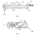
- FIGS. 9-11 show a wiper blade 2, in which for the two injection channels 9 and 10, only a single, common hose 15 is provided for connection to the supply unit 16 and this only in the wiper blade center of the injection channel 9 has the port 15.1.
- the two spray channels 9 and 10 are fluidly connected to one another via a connecting piece 25 accommodated in the cover cap 14 there.
- the heating element 20 is guided in this embodiment by the spray channels 9 and 10 of the wiper blade 2 so that it starts from the wiper blade center to the wiper blade end 2.1, there through the connector 25 into the spray channel 10, in this to the wiper blade end 2.2 and from there in the spray 9 extends back into the wiper blade center.
- the heating element 20 extends, for example, only within the wiper blade 2 and not within the hose 15 connected to the connection 15.1.
- the two ends of the heating element 20 are sealed out of the spray channel 9 at a connection piece 26 forming the connection 15.1.
- the fitting 26 is for this purpose according to the Figures 10 and 11 sleeve-shaped or tubular, with a channel open at both ends 27, which is part of the spray channel 9 and in the side of a connecting piece 28 for connecting the single hose 15 opens.
- In the channel 27 continue to open two additional auxiliary nozzle 29 and 30 such that the axes of the nozzle are opposite to the axis of the channel 27 inclined.
- the ends of the heating element 20 are sealed out of the spray channel 9 led out.
- the installation of the wiper blade 2 of FIG. 9 with the heating element 20 is carried out, for example, so that the heating element 20 is inserted with one end ahead, first through the auxiliary port 19 in the spray 9, then via the connector 25 through the injection channel 10 and then from the wiper blade end 2.2 back into the spray 9 that this end finally passes through the auxiliary nozzle 30 from the channel 27 to the outside.
- a wall portion 31 is provided in the interior of the channel 27 in the region of the auxiliary nozzle 30, which in pushing through the heating element 20 in this case the leading end in the auxiliary nozzle 30 and for this purpose a parallel to the axis of the opening of the auxiliary nozzle 30 extending system - or Leit Structure forms.
- the two ends of the heating element 20 which are led out in a sealed manner by the auxiliary sockets 29 and 30 are connected to the driver stage 22, for example via corresponding electrical connecting lines.
- FIG. 12 finally shows a wiper blade 2a, which has only one injection channel, namely the injection channel 9, through which the heating element 20 extends between the two wiper blade ends 2a.1 and 2a.2. From both ends, the heating element 20 outside the spray channel 9, ie, for example, in a channel in the region of the spoiler-like profile section of the wiper blade element 8 is returned to the wiper blade center, where the ends of the heating element 20 are then connected, for example via electrical lines to the driver stage 22.
- the wiper blade 2a has in the wiper blade center on the connection 15.1 for the hose 15 for supplying the washing and cleaning liquid. Basically, however, in this embodiment, it is also possible at the wiper blade end 2a.2 the connection 15.2 for the Provide hose 15.
- heating elements 20 and 20a and 20b also extend in the hose lines 15 for supplying the washing and cleaning liquid.
- the respective heating element 20 or 20a and 20b is a heating wire with a round cross section.
- the heating element forming the respective heating element may also have a different cross section.
Landscapes
- Engineering & Computer Science (AREA)
- Mechanical Engineering (AREA)
- Water Supply & Treatment (AREA)
- Nozzles (AREA)
Description
Die Erfindung betrifft ein Wischblatt zum Reinigen von Scheiben an Fahrzeugen nach dem Oberbegriff des Anspruchs 1 sowie eine Scheibenwischanlage unter Verwendung eines erfindungsgemäßen Wischblatts.The invention relates to a wiper blade for cleaning windows on vehicles according to the preamble of claim 1 and a windshield wiper system using a wiper blade according to the invention.
Ein Wischblatt nach dem Oberbegriff des Anspruchs 1 ist aus der
Bekannt sind insbesondere auch flache Wischblätter, d.h. als Flachwischblätter ausgebildete Wischblätter, die im Wesentlichen aus einem sich über die gesamte Länge des jeweiligen Wischblattes erstreckenden profil- oder leistenartigen Wischblattkörper mit wenigstens einem zumindest eine Wischlippe bildenden Wischgummi sowie aus wenigstens einer Federschiene bestehen. Bekannt ist auch derartige flache Wischblätter mit Spritzkanälen auszubilden, die sich jeweils an einer Wischblattlängsseite erstrecken und eine Vielzahl von Düsenöffnungen aufweisen, über die während des Wischbetriebes eine den Spritzkanälen von einer fahrzeugseitigen Versorgungseinheit unter Druck zugeführte Wasch- und Reinigungsflüssigkeit (in der Regel Wasser ggs. mit Reinigungs- und/oder Frostschutzzusätzen) auf die betreffende Fahrzeugscheibe ausgebracht werden kann (
Bekannt Ist weiterhin (
Bekannt ist weiterhin auch (
Bekannt ist schließlich auch (
Bei dem erfindungsgemäßen Wischblatt ist das wenigstens eine Heizelement innerhalb des Wischblattes so vorgesehen, dass es dort zumindest mit einer Teillänge innerhalb des wenigstens einen Spritzkanals verläuft, so dass mit dem Heizelement eine unmittelbare Beheizung dieses Spritzkanals bzw, der im Spritzkanal geführten Wasch- und Reinigungsflüssigkeit und damit auch eine unmittelbare Beheizung der wenigstens einen Düsenöffnung des Spritzkanals erfolgt. Bevorzugt ist der wenigstens eine Spritzkanal mit einer Vielzahl von Düsenöffnungen versehen.In the wiper blade according to the invention, the at least one heating element within the wiper blade is provided so that it extends at least a partial length within the at least one spray channel, so that with the heating element directly heating this spray channel or, guided in the spray channel washing and cleaning liquid and thus also an immediate heating of the at least one nozzle opening of the spray channel he follows. Preferably, the at least one injection channel is provided with a plurality of nozzle openings.
Für die Montage des wenigstens einen Heizelementes, welches bevorzugt von einem Heizleiter oder Heizdraht gebildet ist, sind grundsätzlich keine zusätzlichen Maßnahmen am Wischblatt erforderlich, d.h. für das Verlegen des Heizelementes wird der wenigstens eine Spritzkanal genutzt, der sich entlang einer Wischblattlängsseite erstreckt. Weist das Wischblatt mehrere Spritzkanäle auf, beispielsweise wenigstens zwei Spritzkanäle, von denen sich jeder an einer Längsseite des Wischblattes befindet, so erstreckt sich die von dem wenigstens einen Heizelement gebildete Heizschleife durch sämtliche Spritzkanäle, und dabei beispielsweise so, dass das wenigstens eine Heizelement innerhalb des Wischblattes ausschließlich in den Spritzkanälen aufgenommen ist, und zwar allenfalls ausgenommen von Teillängen an den beiden Wischblattenden.For the assembly of the at least one heating element, which is preferably formed by a heating conductor or heating wire, no additional measures are basically required on the wiper blade, ie for laying the heating element of the at least one injection channel is used, which extends along a wiper blade longitudinal side. If the wiper blade has a plurality of injection channels, for example at least two injection channels, each of which is located on a longitudinal side of the wiper blade, then extends the heating loop formed by the at least one heating element through all spray channels, and thereby, for example, so that the at least one heating element is housed within the wiper blade exclusively in the spray channels, except at most of partial lengths at the two wiper blade ends.
Bei einer bevorzugten Ausführungsform der Erfindung bildet das wenigstens eine Heizelement wenigstens einen zusätzlichen Heizelement-Abschnitt, der sich außerhalb des Wischblattes erstreckt und zum Beheizen zumindest einer Teillänge einer Versorgungsleitung für die Wasch- und Reinigungsflüssigkeit dient, die (Teillänge) sich in einem Bereich des Fahrzeugs befindet, in dem die Gefahr einer Vereisung der Versorgungsleitung besteht. Auch dieser zum Beheizen der Versorgungsleitung dienende Heizelement-Abschnitt ist bevorzugt im Innenraum bzw. Lumen der wenigstens einen Versorgungsleitung angeordnet.In a preferred embodiment of the invention, the at least one heating element forms at least one additional heating element section which extends outside the wiper blade and serves to heat at least a partial length of a supply line for the washing and cleaning fluid, which (partial length) is in an area of the vehicle is in danger of icing up the supply line. This heating element section serving for heating the supply line is also preferably arranged in the interior or lumen of the at least one supply line.
Durch die erfindungsgemäße Ausbildung erfolgt eine unmittelbare Erwärmung der Wasch- und Reinigungsflüssigkeit zumindest in dem wenigstens einen Spritzkanal des Wischblattes, so dass bei reduziertem Bedarf an elektrischer Energie ein wirksamen Erwärmen der das Heizelement umströmenden Wasch- und Reinigungsflüssigkeit erreicht wird. Mit der Erfindung wird nicht nur ein Vereisen des wenigstens einen Wischblatt-Spritzkanals und der dortigen Düsen- oder Düsenöffnungen sowie der Versorgungsleitung wirksam verhindert, sondern durch das Erwärmen der Wasch- und Reinigungsflüssigkeit wird auch die Reinigungswirkung wesentlich verbessert.As a result of the construction according to the invention, the washing and cleaning liquid is heated at least in the at least one injection channel of the wiper blade so that effective heating of the washing and cleaning liquid flowing around the heating element is achieved with reduced demand for electrical energy. With the invention not only icing of the at least one wiper blade spray channel and the nozzle or nozzle openings therein and the supply line is effectively prevented, but by the heating of the washing and cleaning liquid and the cleaning effect is substantially improved.
Bei einer bevorzugten Ausbildung der Scheibenwischanlage wird das wenigstens eine Heizelement in Abhängigkeit von Umgebungsparametern und/oder in Abhängigkeit von Betriebsparametern des Fahrzeugs automatisch gesteuert oder geregelt. Eine solche Steuerung oder Regelung ist dann beispielsweise so ausgebildet, dass das Einschalten des wenigstens einen Heizelementes z.B. bei aktivierter Wischanlage in Abhängigkeit von der Außentemperatur automatisch erfolgt, und zwar dann, wenn ein vorgegebener Schwellwert, beispielsweise eine Außentemperatur von ca. 5°C unterschritten wird. Die Steuerung bzw. Regelung des wenigstens einen Heizelementes erfolgt weiterhin bevorzugt so, dass das Heizelement nach dem Einschalten zunächst über eine kurze Zeitdauer mit einer erhöhten Heizleistung betrieben wird, um eine eventuell bestehende Vereisung schnell zu beseitigen bzw. die Wasch- und Reinigungsflüssigkeit schnell zu erhitzen und so möglichst verzögerungsfrei die Betriebsfähigkeit der Scheibenwaschanlage herzustellen.In a preferred embodiment of the windscreen wiper system, the at least one heating element is automatically controlled or regulated as a function of environmental parameters and / or as a function of operating parameters of the vehicle. Such a control or regulation is then, for example, designed such that the switching on of the at least one heating element, for example when the wiper system is activated, takes place automatically as a function of the outside temperature, specifically if a predetermined threshold value, for example a Outside temperature of about 5 ° C is exceeded. The control or regulation of the at least one heating element is further preferably carried out so that the heating element is initially operated after switching on for a short period of time with an increased heating power to quickly eliminate any existing icing or to heat the washing and cleaning fluid quickly and as delay as possible to produce the operability of the windscreen washer system.
Die für die Steuerung oder Regelung des wenigstens einen Heizelementes verwendeten Betriebsparameter sind beispielsweise die Fahrgeschwindigkeit des Fahrzeugs und/oder die Wischanlagenfrequenz, d.h. die Frequenz oder Geschwindigkeit, mit der das Schwenken des wenigstens einen Wischarmes der Scheibenwischanlage erfolgt.The operating parameters used for the control or regulation of the at least one heating element are, for example, the traveling speed of the vehicle and / or the wiper frequency, i. the frequency or speed at which the pivoting of the at least one wiper arm of the windshield wiper system takes place.
Weiterbildungen, Vorteile und Anwendungsmöglichkeiten der Erfindung ergeben sich auch aus der nachfolgenden Beschreibung von Ausführungsbeispielen und aus den Figuren. Dabei sind alle beschriebenen und/oder bildlich dargestellten Merkmale für sich oder in beliebiger Kombination grundsätzlich Gegenstand der Erfindung, unabhängig von ihrer Zusammenfassung in den Ansprüchen oder deren Rückbeziehung. Auch wird der Inhalt der Ansprüche zu einem Bestandteil der Beschreibung gemacht.Further developments, advantages and applications of the invention will become apparent from the following description of exemplary embodiments and from the figures. In this case, all described and / or illustrated features alone or in any combination are fundamentally the subject of the invention, regardless of their summary in the claims or their dependency. Also, the content of the claims is made an integral part of the description.
Die Erfindung wird im Folgenden anhand der Figuren an Ausführungsbeispielen näher erläutert. Es zeigen:
-
Fig. 1 in vereinfachter Darstellung und in Seitenansicht einen Wischarm zusammen mit einem an diesen Wischarm befestigten Wischblatt gemäß der Erfindung und mit zugehörigen Versorgungs- und Steuereinrichtungen; -
Fig. 2 einen Querschnitt durch das Wischblatt derFigur 1 ; -
Fig. 3 in vereinfachter Teildarstellung einen Längsschnitt durch das Wischblatt derFigur 1 im Bereich eines Wischblattendes; -
Fig. 4 - 9 jeweils in schematischer Darstellung die Führung des wenigstens einen elektrischen Heizelementes bzw. die von dem wenigstens einem Heizelement gebildete oder gebildeten Heizschleife(n) innerhalb des Wischblattes bei verschiedenen Ausführungsformen, wobei die Enden der innerhalb des Wischblattes verlaufenden Heizelement-Abschnitte bzw. Heizschleifen jeweils mit " + " bzw. "- " bezeichnet sind; -
Fig. 10 und11 ein Anschlussstück zur Verwendung bei der Ausführung derFigur 9 -
Fig. 12 in einer Darstellungen ähnlich denFiguren 4 - 9 eine weitere Ausführung des erfindungsgemäßen Wischblattes.
-
Fig. 1 in a simplified representation and in side view of a wiper arm together with a wiper blade attached to this wiper arm according to the invention and with associated supply and control devices; -
Fig. 2 a cross section through the wiper blade ofFIG. 1 ; -
Fig. 3 in a simplified partial view a longitudinal section through the wiper blade ofFIG. 1 in the area of a wiper blade end; -
Fig. 4-9 in each case a schematic representation of the guidance of the at least one electrical heating element or the heating loop (s) formed or formed by the at least one heating element within the wiper blade in various embodiments, wherein the ends of the heating element sections or heating loops running within the wiper blade are respectively denoted by "+" and "-"; -
Fig. 10 and11 a fitting for use in the execution ofFIG. 9 in side view and in longitudinal section; -
Fig. 12 in a representation similar to theFIGS. 4 to 9 a further embodiment of the wiper blade according to the invention.
In den
Das Wischblatt 2 ist jeweils als flaches Wischblatt ausgebildet und besteht entsprechend der
Der Wischblattkörper 5 bzw. das diesen Körper bildende Profil, die Federschiene 6 sowie auch das Wischblattelement 8 mit den beiden Spritzkanälen 9 und 10 erstrecken sich jeweils über die gesamte Länge des Wischblattes. An den beiden Enden sind die Spritzkanäle 9 und 10 jeweils durch einen Verschlussstopfen 13 (
Zum Zuführen der Wasch- und Reinigungsflüssigkeit dienen zwei Schlauchleitungen 15, die teilweise entlang des Wischarmes 1 verlaufen und die jeweils mit einem Ausgang einer Versorgungseinheit 16, d.h. mit einem Ausgang einer Pumpe 17 dieser Versorgungseinheit verbunden sind, welche zusätzlich zu der durch einen Elektromotor angetriebenen Pumpe 17 u.a. auch einen die Wasch- und Reinigungsflüssigkeit aufnehmenden Tank 18 aufweist. Mit 19 ist eine Steuereinrichtung bezeichnet, die bei eingeschalteter Scheibenwischanlage und auch eingeschalteter Scheibenwaschanlage u.a. die Pumpe 17 derart steuert, dass den Spritzkanälen 9 und 10 die Wasch- und Reinigungsflüssigkeit über die Schlauchleitungen 15 mit dem erforderlichen Druck zugeführt wird, so dass diese Wasch- und Reinigungsflüssigkeit über die Düsenöffnungen 11 auf die Fahrzeugscheibe 12 ausgebracht werden kann.For supplying the washing and cleaning liquid are two
Eine Besonderheit besteht darin, dass das Wischblatt 2 bzw. dessen Spritzkanäle 9 und 10 sowie die zugehörigen Düsen 11, aber auch die Schlauchleitungen 15, letztere zumindest auf einer Teillänge, elektrisch beheizt sind, und zwar durch ein Heizelement, welches in den
Das Heizelement 20 ist bei der in den
- Ausgehend von einem Heizelementende durch eine Schlauchleitung 15 an die Mitte des
Wischblattes 2, - von der Mitte des
Wischblattes 2im Spritzkanal 9 an ein Wischblattende 2.2, - von dem Wischblattende 2.2 abgedichtet durch die
Verschlussstopfen 13im Spritzkanal 10 an das Wischblattende 2.1, - von dem Wischblattende 2.1 wiederum abgedichtet durch die
Verschlussstopfen 13hindurchgeführt im Spritzkanal 9 zu der Mitte desWischblattes 2 und - von der Mitte des
Wischblattes 2 durch die andere Schlauchleitung 15 an das andere Heizelementende.
- Starting from a Heizelementende through a
hose 15 to the center of thewiper blade 2, - from the center of the
wiper blade 2 in thespray channel 9 to a wiper blade end 2.2, - from the wiper blade end 2.2 sealed by the sealing
plug 13 in thespray channel 10 to the wiper blade end 2.1, - from the wiper blade end 2.1 in turn sealed by the sealing
plug 13 passed in thespray channel 9 to the center of thewiper blade 2 and - from the center of the
wiper blade 2 through theother hose 15 to the other end of the heating element.
Im Bereich der Wischblattenden ist das Heizelement 20 jeweils durch die dortige Abdeckkappe 14 abgedeckt.In the area of the wiper blade ends, the
Zum Einführen des Heizelementes 20 in die Schlauchleitungen 15 sind diese im Bereich der Versorgungseinheit 10 mit einem T-Stück 21 versehen, welches eine mit der betreffenden Schlauchleitung 15 und einem Anschluss der Pumpe 17 verbundenen Strömungskanal bildet, in den das jeweilige Heizelement 20 abgedichtet eingeführt ist. Für den Betrieb des Heizelementes 20 ist eine Treiberstufe 22 vorgesehen, die ebenfalls von der Steuereinrichtung 19 angesteuert wird, und zwar unter Berücksichtigung verschiedener Schalt- und/oder Regelgrößen bzw. -parameter. So erfolgt beispielsweise das Aktivieren des Heizelementes 20 erst dann, wenn auch die Wischanlage und/oder die Versorgungseinheit 16 aktiviert sind, und zwar beispielsweise in Abhängigkeit von einem mit der Steuereinheit 19 verbundenen Regensensor 23.To insert the
Weiterhin erfolgt der Betrieb des Heizelementes 20 bevorzugt in Abhängigkeit von der Außentemperatur, d.h. in Abhängigkeit von dem Messsignal wenigstens eines diese Außentemperatur erfassenden und mit der Steuereinrichtung 19 ebenfalls verbundenen Temperatursensor 24. Diese von der Außentemperatur abhängige Regelung der Leistung des Heizelementes 20 erfolgt dann beispielsweise in Stufen oder aber stufenlos derart, dass das Heizelement 20 grundsätzlich erst dann aktiviert wird, wenn die Außentemperatur einen vorgegebenen Schwellwert unterschreitet, d.h. die Aktivierung des Heizelementes 20 erfolgt z.B. erst dann, wenn die Außentemperatur gleich oder kleiner 5°C ist. Die anschließende Regelung der Heizleistung des Heizelementes 20 erfolgt dann z.B. temperaturabhängig, d.h. mit abnehmender Temperatur wird die Heizleistung des Heizelementes 20 kontinuierlich oder in Stufen erhöht. Weitere Parameter für die Regelung oder Steuerung der Heizleistung des Heizelementes 20 sind beispielsweise die Fahrgeschwindigkeit des Fahrzeugs und/oder die Wischanlagenfrequenz, und zwar in der Form, dass bei einer Erhöhung der Fahrgeschwindigkeit und/oder der Wischanlagenfrequenz über die die Treiberstufe 22 ansteuernde Steuereinrichtung 19 auch eine Erhöhung der Heizleistung des Heizelementes 20 erfolgt.Furthermore, the operation of the
Durch das elektrische Heizelement 20 wird ein Vereisen der Spritzkanäle 9 und 10, der dortigen Düsenöffnungen 11 sowie der Schlauchleitungen 15 wirksam verhindert, zumal das im Lumen der Spritzkanäle 9 und 10 sowie der Schlauchleitungen 15 lose verlegte Heizelemente 20 von der Wasch- und Reinigungsflüssigkeit umströmt unmittelbar auf diese einwirkt. Weiterhin lässt sich durch Erwärmen der Wasch- und Reinigungsflüssigkeit auch deren Reinigungswirkung wesentlich verbessern.By the
Die beiden Schlauchleitungen 15 sind mit den Spritzkanälen 9 und 10 jeweils in der Mitte des Wischblattes 2, beispielsweise über im Adapter 3 integrierte Anschlüsse 15.1 verbunden.The two
Um ein vereinfachtes Austauschen des gesamten Wischblattes 2 zu ermöglichen, ist das Heizelement 20 vorzugsweise mehrteilig ausgebildet, d.h. bestehend aus einem sich durch die Spritzkanäle 9 und 10 erstreckenden Abschnitt sowie aus zwei sich jeweils in den Schlauchleitungen 15 erstreckenden Abschnitten, wobei die Abschnitte im Bereich des Adapters 3 elektrisch miteinander zu dem Heizelement 20 verbunden sind. Der Adapter 3 ist hierfür zweiteilig ausgeführt, und zwar bevorzugt derart, dass beim Verbinden der beiden Adapterteile sowohl die Fluidverbindung zwischen den Schlauchleitungen 15 und den Spritzkanälen 9 bzw. 10, als auch die elektrische Verbindung zwischen den dann in Serie miteinander verbundenen Abschnitten des Heizelementes 20 hergestellt wird.In order to facilitate a simplified replacement of the
Die
Den Ausführungen der
Die
Die
Die
Allen vorgenannten Ausführungsformen ist gemeinsam, dass jeder Spritzkanal 9 bzw. 10 jeweils über eine eigene Schlauchleitung 15 mit der Versorgungseinheit 16 verbunden ist und hierfür einen eigenen Anschluss 15.1 für die betreffende Schlauchleitung 15 aufweist.All of the aforementioned embodiments have in common that each
Die
Die Montage des Wischblattes 2 der
Die beiden durch die Hilfsstutzen 29 und 30 abgedichtet herausgeführten Enden des Heizelementes 20 sind beispielsweise über entsprechende elektrische Verbindungsleitungen mit der Treiberstufe 22 verbunden.The two ends of the
Die
Das Wischblatt 2a weist in der Wischblattmitte den Anschluss 15.1 für die Schlauchleitung 15 zum Zuführen der Wasch- und Reinigungsflüssigkeit auf. Grundsätzlich besteht aber bei dieser Ausführungsform auch die Möglichkeit, an dem Wischblattende 2a.2 den Anschluss 15.2 für die Schlauchleitung 15 vorzusehen.The
Die Erfindung wurde voranstehend an Ausführungsbeispielen beschrieben. Es versteht sich, dass zahlreiche Änderungen sowie Abwandlungen möglich sind, ohne dass dadurch der der Erfindung zugrundeliegende Erfindungsgedanke verlassen wird.The invention has been described above by means of exemplary embodiments. It is understood that numerous changes and modifications are possible without thereby departing from the inventive concept underlying the invention.
So wurde beispielsweise bei den im Zusammenhang mit den
Weiterhin wurde vorstehend davon ausgegangen, dass das jeweilige Heizelement 20 bzw. 20a und 20b ein Heizdraht mit rundem Querschnitt ist. Selbstverständlich kann der das jeweilige Heizelement bildende Heizdraht auch einen anderen Querschnitt aufweisen.Furthermore, it was assumed above that the
Claims (15)
- Wiper blade for cleaning windows on vehicles, in particular motor vehicles, having at least one preferably bar-like wiper blade body (5), having at least one wiper rubber which is fastened to the wiper blade body (5) and forms at least one wiping lip (7.2), having at least one spraying duct (9, 10) on the wiper blade (2, 2a) for a washing and cleaning liquid, and having at least one nozzle opening (11) on the spraying duct (9, 10) for ejecting the washing and cleaning liquid, at least one electric heating element (20, 20a, 20b) being provided which extends at least with a part length through the at least one spraying duct (9, 10), characterized in that the at least one spraying duct (9, 10) is formed on a longitudinal side of the wiper blade (2, 2a), in that the at least one heating element (20, 20a, 20b) forms at least one heating loop within the wiper blade (2, 2a), and in that the ends of the at least one heating loop which is formed within the wiper blade (2, 2a) are provided at one wiper blade end (2.2, 2a.2) or else between the wiper blade ends (2.1, 2.2; 2a.1, 2a.2), for example in the centre or approximately in the centre of the wiper blade (2, 2a).
- Wiper blade according to Claim 1, characterized in that it is configured as a flat wiper blade at least consisting of the bar-like wiper blade body (5) with the at least one wiper rubber (7) and with at least one spring bar (6), and in that the at least one spraying duct (9, 10) is formed on a longitudinal side of the wiper blade (2, 2a) in a section there of the wiper blade body (5) or of a wiper blade element (8) which is connected to the wiper blade body.
- Wiper blade according to either of the preceding claims, characterized in that a multiplicity of nozzle openings are provided along the at least one spraying duct (9, 10).
- Wiper blade according to one of the preceding claims, characterized in that in each case at least one spraying duct (9, 10) is provided on both wiper blade longitudinal sides, and in that the at least one heating element (20, 20a) extends with at least one part length through all the spraying ducts (9, 10).
- Wiper blade according to one of the preceding claims, characterized in that the at least one spraying duct (9, 10) is closed at least at one wiper blade end (2.1, 2.2; 2a.1, 2a.2) by way of a closure (13), through which the heating element (20, 20a, 20b) is guided in a sealed manner, and in that a covering cap (14) which is produced, for example, from plastic and covers and/or fixes the heating element (20, 20a, 20b) on a part length which is guided out of the closure (13) is provided at the wiper blade end (2.1, 2.2; 2a.1, 2a.2).
- Wiper blade according to Claim 1, characterized in that the ends of the at least one heating loop which is formed within the wiper blade (2, 2a) are provided on or in the region of at least one connector (15.1, 15.2) for connecting the at least one spraying duct (9, 10) to a supply line (15) for feeding in the washing and cleaning liquid.
- Wiper blade according to one of the preceding claims, characterized in that the at least one heating element (20, 20a, 20b) within the wiper blade (2, 2a) is arranged exclusively or virtually exclusively in the at least one spraying duct (9, 10).
- Wiper blade according to one of the preceding claims, characterized in that the at least one heating element (20, 20a, 20b) is provided with at least one part length so as to run in or on the wiper blade (2, 2a) outside the at least one spraying duct (9, 10).
- Wiper blade according to one of the preceding claims, characterized in that the at least one heating loop which is formed by the at least one heating element (20, 20a, 20b) within the wiper blade can be connected via external connectors to an electric supply unit (22), and in that the external connectors are formed by electrical lines or else at least partially by a part length of the at least one heating element (20, 20a, 20b), preferably by a part length of the at least one heating element (20, 20a, 20b), which part length heats at least one supply line (15) for feeding in the washing and cleaning liquid.
- Wiper blade according to one of the preceding claims, characterized in that the at least one heating element (20, 20a, 20b) is formed by a heating wire, preferably by an encapsulated heating wire, for example from PTC.
- Wiper blade according to one of the preceding claims, characterized in that the at least one wiper rubber (7) is fastened exchangeably to the wiper blade body (5).
- Window wiping system for cleaning windows on vehicles, having at least one wiping arm (1) and at least one wiper blade (2, 2a) which is provided on the wiping arm (1) with at least one spraying duct (9, 10) which has at least one nozzle opening (11) and is connected via a supply line (15) to a supply unit (16) for a washing and cleaning liquid, characterized in that the at least one wiper blade (2, 2a) is configured according to one of the preceding claims, and in that the at least one electric heating element (20, 20a, 20b) is connected to a vehicle-side electric supply unit or a driver stage (22) of the said supply unit.
- Window wiping system according to Claim 12, characterized in that the at least one heating element (20, 20a, 20b) consists of a heating element section which is arranged in the at least one wiper blade (2, 2a) and of at least one further heating element section for heating at least one part length of the at least one supply line (15).
- Window wiping system according to one of the preceding claims, characterized by an electric supply unit (19, 22), by way of which the at least one heating element (20, 20a, 20b) or the heating output of the said heating element is switched or controlled depending on ambient parameters (for example, external temperature at the vehicle) and/or operating parameters of the vehicle (for example, driving speed and/or wiping system frequency).
- Window wiping system according to one of the preceding claims, characterized in that the electric supply unit (19, 22) is configured to control or regulate the at least one heating element (20, 20a, 20b) in such a way that the at least one heating element (20, 20a, 20b) is switched on only when the external temperature at the vehicle undershoots a predefined threshold value, for example a temperature of approximately 5°C, and/or in that the at least one heating element (20, 20a, 20b) is first of all operated with an increased heating output after the respective switching-on operation.
Priority Applications (1)
| Application Number | Priority Date | Filing Date | Title |
|---|---|---|---|
| PL09734764T PL2265477T3 (en) | 2008-04-22 | 2009-04-20 | Wiper blade and windshield wiper system having such a wiper blade |
Applications Claiming Priority (2)
| Application Number | Priority Date | Filing Date | Title |
|---|---|---|---|
| DE102008020227A DE102008020227A1 (en) | 2008-04-22 | 2008-04-22 | Wiper blade and windscreen wiper system with such a wiper blade |
| PCT/EP2009/054662 WO2009130183A1 (en) | 2008-04-22 | 2009-04-20 | Wiper blade and windshield wiper system having such a wiper blade |
Publications (2)
| Publication Number | Publication Date |
|---|---|
| EP2265477A1 EP2265477A1 (en) | 2010-12-29 |
| EP2265477B1 true EP2265477B1 (en) | 2014-09-17 |
Family
ID=40762481
Family Applications (1)
| Application Number | Title | Priority Date | Filing Date |
|---|---|---|---|
| EP09734764.5A Active EP2265477B1 (en) | 2008-04-22 | 2009-04-20 | Wiper blade and windshield wiper system having such a wiper blade |
Country Status (4)
| Country | Link |
|---|---|
| EP (1) | EP2265477B1 (en) |
| DE (1) | DE102008020227A1 (en) |
| PL (1) | PL2265477T3 (en) |
| WO (1) | WO2009130183A1 (en) |
Families Citing this family (11)
| Publication number | Priority date | Publication date | Assignee | Title |
|---|---|---|---|---|
| DE102011012634A1 (en) | 2011-02-28 | 2012-08-30 | Valeo Systèmes d'Essuyage | Wiper blade for attaching to wiper arm of wiping device for cleaning pane of motor car, has distributor members comprising spray nozzle and vent hole, where liquid escapes from members in position of valve element over nozzle and vent hole |
| EP2808208A1 (en) * | 2013-05-31 | 2014-12-03 | Valeo Systèmes d'Essuyage | Longitudinal substrate and wiper for motor vehicle |
| DE102015015553B4 (en) * | 2015-12-03 | 2021-01-14 | A.RAYMOND et Cie. SCS | Device for guiding a fluid on a wiper arm of an automobile, wiper arm and wiper arm unit of an automobile, which in particular have such a device, and a method for producing a device for guiding a fluid on a wiper arm of an automobile |
| FR3086617B1 (en) * | 2018-09-28 | 2021-01-29 | Valeo Systemes Dessuyage | WINDSCREEN WIPER BLADE SPRAYING LIQUID FOR MOTOR VEHICLE WINDOWS, AND IMPROVING THE WATERPROOFING OF THIS BROOM |
| DE102018251742A1 (en) * | 2018-12-27 | 2020-07-02 | Robert Bosch Gmbh | Wiper blade device |
| DE102018251765A1 (en) * | 2018-12-28 | 2020-07-02 | Robert Bosch Gmbh | Method for heating a wiper device |
| DE102019216430A1 (en) * | 2019-10-25 | 2021-04-29 | Robert Bosch Gmbh | Wiper blade, in particular for a motor vehicle |
| DE102019216431A1 (en) | 2019-10-25 | 2021-04-29 | Robert Bosch Gmbh | Wiper blade, in particular for a motor vehicle |
| DE102020203427A1 (en) * | 2020-03-17 | 2021-09-23 | Robert Bosch Gesellschaft mit beschränkter Haftung | Fluid connection for a wiper blade and such a wiper blade |
| DE102020211424A1 (en) | 2020-09-11 | 2022-03-17 | Robert Bosch Gesellschaft mit beschränkter Haftung | Wiper blade, in particular for a motor vehicle |
| DE102021210130A1 (en) * | 2021-09-14 | 2023-03-16 | Robert Bosch Gesellschaft mit beschränkter Haftung | Fluid guide device for a windscreen wiper |
Citations (1)
| Publication number | Priority date | Publication date | Assignee | Title |
|---|---|---|---|---|
| US6137084A (en) * | 1998-10-07 | 2000-10-24 | Thomas; Paul Douglas | Heating element for heated windshield wiper |
Family Cites Families (12)
| Publication number | Priority date | Publication date | Assignee | Title |
|---|---|---|---|---|
| GB2121681B (en) * | 1982-05-06 | 1985-11-06 | John Keen | Windscreen wash system with electrical heating means |
| DE8510687U1 (en) * | 1985-04-12 | 1985-09-19 | Nothacker, Lutz, 8632 Neustadt | Tandem windscreen washer system for motor vehicles with an additional strip sponge |
| US5426814A (en) | 1994-01-31 | 1995-06-27 | Minnick; Leonard J. | Heated windshield wiper with fluid dispensing means |
| DE4404409A1 (en) | 1994-02-11 | 1995-08-17 | Kammerer Gmbh M | Windscreen washer system for motor vehicles |
| DE29813251U1 (en) * | 1997-11-23 | 1998-11-05 | Seeger Marketing + Consulting GmbH, 76571 Gaggenau | Wiper blade |
| DE50010074D1 (en) * | 1999-03-31 | 2005-05-25 | Raymond A & Cie | Electrically heated hose for windscreen washer |
| DE10000381A1 (en) | 2000-01-07 | 2001-11-22 | Valeo Auto Electric Gmbh | Wiper blade for cleaning windows on vehicles, especially motor vehicles |
| DE10037608B4 (en) * | 2000-08-02 | 2006-01-05 | Siemens Ag | Heatable cleaning device and method for heating such a cleaning device |
| DE10039290B4 (en) | 2000-08-11 | 2013-01-31 | Valeo Auto-Electric Wischer Und Motoren Gmbh | wiper device |
| CZ20033071A3 (en) | 2001-05-14 | 2004-10-13 | Microheatáinc | Automobile windshield wiper with washer |
| DE10234267A1 (en) | 2002-07-27 | 2004-02-05 | Robert Bosch Gmbh | Wiper blade for cleaning motor vehicle windscreens has a flexible ribbon-type elongated supporting element and an element for heating the wiper blade to ensure movement in winter conditions |
| DE10323998A1 (en) | 2003-05-27 | 2004-12-23 | Valeo Systèmes d`Essuyage | Wiper blade for cleaning vehicle windscreen has wiper body and rubber wiper element as separate parts and at least one spray channel integrated into wiper body for transporting liquid |
-
2008
- 2008-04-22 DE DE102008020227A patent/DE102008020227A1/en not_active Ceased
-
2009
- 2009-04-20 WO PCT/EP2009/054662 patent/WO2009130183A1/en active Application Filing
- 2009-04-20 PL PL09734764T patent/PL2265477T3/en unknown
- 2009-04-20 EP EP09734764.5A patent/EP2265477B1/en active Active
Patent Citations (1)
| Publication number | Priority date | Publication date | Assignee | Title |
|---|---|---|---|---|
| US6137084A (en) * | 1998-10-07 | 2000-10-24 | Thomas; Paul Douglas | Heating element for heated windshield wiper |
Also Published As
| Publication number | Publication date |
|---|---|
| WO2009130183A1 (en) | 2009-10-29 |
| DE102008020227A1 (en) | 2009-11-12 |
| PL2265477T3 (en) | 2015-02-27 |
| EP2265477A1 (en) | 2010-12-29 |
Similar Documents
| Publication | Publication Date | Title |
|---|---|---|
| EP2265477B1 (en) | Wiper blade and windshield wiper system having such a wiper blade | |
| EP2331371B1 (en) | Wiper arm/wiper blade connection, wiper blade and windscreen wiper installation | |
| EP2328784B1 (en) | Wiperblade-wiperarm connection and a wiperblade | |
| EP1998987B1 (en) | Wiper blade | |
| DE69827130T2 (en) | DEFROSTING WINDSHIELDS | |
| DE19906197B4 (en) | Windscreen wiper with spray nozzle and check valve | |
| DE102009043695A1 (en) | wiper blade | |
| EP1334015A2 (en) | Heatable washer system | |
| DE102009048212A1 (en) | Flat aqua-wiper blade for use in windscreen wiper system of vehicle, has flexible liquid line and/or flexible electrical connector extending from connection element to wiper blade-side adapter part in longitudinal direction | |
| WO2010043383A1 (en) | Washing system for vehicle windows and check valve for such a system | |
| EP2334523B1 (en) | Washing system for vehicle windows and check and bleed valve for such a system | |
| EP1071593B1 (en) | Windshield wiper | |
| DE102014119452A1 (en) | Washing liquid heating device, which is integrated in a washing container | |
| EP1257448B1 (en) | System for heating liquid in a conduit system | |
| DE19807594B4 (en) | Heated spray nozzle head | |
| DE102005030972A1 (en) | Wiping device for windscreens has fluid path in at least one wiper blade with fluid able to flow through it at least during heating mode of wiper use | |
| DE19826846C1 (en) | Electrically heated windscreen cleaning device for automobile has electric heating element associated with washing fluid line leading to washing jets in jet body fitted to windscreen wiper arm | |
| DE19902431B4 (en) | Intermediate piece with a connection of washing liquid lines of a window cleaning system | |
| DE102009059117A1 (en) | Wiping system for motor vehicle, has pump device provided for subjecting outlet devices with washing liquid, where washing liquid is alternatively supplied to outlet devices when conveying direction of pump device is reversed | |
| DE102012222038A1 (en) | Cleaning system for disk of motor vehicle, has hydraulic line for transporting cleaning liquid, where hydraulic line has inlet end and outlet end, and connecting element is attached to inlet end for connection with terminal of liquid source | |
| DE102018212057A1 (en) | wiper device | |
| DE102021210128A1 (en) | Fluid guide device for a windscreen wiper | |
| WO2022037823A1 (en) | Wiper blade device for a wiper with a spray function | |
| WO2022175067A1 (en) | Nozzle system for cleaning a vehicle part, in particular a window of a motor vehicle, and cleaning method | |
| DE102008064926B3 (en) | wiper blade |
Legal Events
| Date | Code | Title | Description |
|---|---|---|---|
| PUAI | Public reference made under article 153(3) epc to a published international application that has entered the european phase |
Free format text: ORIGINAL CODE: 0009012 |
|
| 17P | Request for examination filed |
Effective date: 20101006 |
|
| AK | Designated contracting states |
Kind code of ref document: A1 Designated state(s): AT BE BG CH CY CZ DE DK EE ES FI FR GB GR HR HU IE IS IT LI LT LU LV MC MK MT NL NO PL PT RO SE SI SK TR |
|
| AX | Request for extension of the european patent |
Extension state: AL BA RS |
|
| DAX | Request for extension of the european patent (deleted) | ||
| 17Q | First examination report despatched |
Effective date: 20120130 |
|
| GRAP | Despatch of communication of intention to grant a patent |
Free format text: ORIGINAL CODE: EPIDOSNIGR1 |
|
| INTG | Intention to grant announced |
Effective date: 20140508 |
|
| GRAS | Grant fee paid |
Free format text: ORIGINAL CODE: EPIDOSNIGR3 |
|
| GRAA | (expected) grant |
Free format text: ORIGINAL CODE: 0009210 |
|
| AK | Designated contracting states |
Kind code of ref document: B1 Designated state(s): AT BE BG CH CY CZ DE DK EE ES FI FR GB GR HR HU IE IS IT LI LT LU LV MC MK MT NL NO PL PT RO SE SI SK TR |
|
| REG | Reference to a national code |
Ref country code: GB Ref legal event code: FG4D Free format text: NOT ENGLISH |
|
| REG | Reference to a national code |
Ref country code: CH Ref legal event code: EP |
|
| REG | Reference to a national code |
Ref country code: IE Ref legal event code: FG4D Free format text: LANGUAGE OF EP DOCUMENT: GERMAN |
|
| REG | Reference to a national code |
Ref country code: AT Ref legal event code: REF Ref document number: 687536 Country of ref document: AT Kind code of ref document: T Effective date: 20141015 |
|
| REG | Reference to a national code |
Ref country code: DE Ref legal event code: R096 Ref document number: 502009009974 Country of ref document: DE Effective date: 20141030 |
|
| REG | Reference to a national code |
Ref country code: SE Ref legal event code: TRGR |
|
| REG | Reference to a national code |
Ref country code: NL Ref legal event code: T3 |
|
| PG25 | Lapsed in a contracting state [announced via postgrant information from national office to epo] |
Ref country code: LT Free format text: LAPSE BECAUSE OF FAILURE TO SUBMIT A TRANSLATION OF THE DESCRIPTION OR TO PAY THE FEE WITHIN THE PRESCRIBED TIME-LIMIT Effective date: 20140917 Ref country code: NO Free format text: LAPSE BECAUSE OF FAILURE TO SUBMIT A TRANSLATION OF THE DESCRIPTION OR TO PAY THE FEE WITHIN THE PRESCRIBED TIME-LIMIT Effective date: 20141217 Ref country code: GR Free format text: LAPSE BECAUSE OF FAILURE TO SUBMIT A TRANSLATION OF THE DESCRIPTION OR TO PAY THE FEE WITHIN THE PRESCRIBED TIME-LIMIT Effective date: 20141218 Ref country code: FI Free format text: LAPSE BECAUSE OF FAILURE TO SUBMIT A TRANSLATION OF THE DESCRIPTION OR TO PAY THE FEE WITHIN THE PRESCRIBED TIME-LIMIT Effective date: 20140917 |
|
| REG | Reference to a national code |
Ref country code: LT Ref legal event code: MG4D |
|
| PG25 | Lapsed in a contracting state [announced via postgrant information from national office to epo] |
Ref country code: LV Free format text: LAPSE BECAUSE OF FAILURE TO SUBMIT A TRANSLATION OF THE DESCRIPTION OR TO PAY THE FEE WITHIN THE PRESCRIBED TIME-LIMIT Effective date: 20140917 Ref country code: CY Free format text: LAPSE BECAUSE OF FAILURE TO SUBMIT A TRANSLATION OF THE DESCRIPTION OR TO PAY THE FEE WITHIN THE PRESCRIBED TIME-LIMIT Effective date: 20140917 Ref country code: HR Free format text: LAPSE BECAUSE OF FAILURE TO SUBMIT A TRANSLATION OF THE DESCRIPTION OR TO PAY THE FEE WITHIN THE PRESCRIBED TIME-LIMIT Effective date: 20140917 |
|
| REG | Reference to a national code |
Ref country code: PL Ref legal event code: T3 |
|
| PG25 | Lapsed in a contracting state [announced via postgrant information from national office to epo] |
Ref country code: RO Free format text: LAPSE BECAUSE OF FAILURE TO SUBMIT A TRANSLATION OF THE DESCRIPTION OR TO PAY THE FEE WITHIN THE PRESCRIBED TIME-LIMIT Effective date: 20140917 Ref country code: EE Free format text: LAPSE BECAUSE OF FAILURE TO SUBMIT A TRANSLATION OF THE DESCRIPTION OR TO PAY THE FEE WITHIN THE PRESCRIBED TIME-LIMIT Effective date: 20140917 Ref country code: IS Free format text: LAPSE BECAUSE OF FAILURE TO SUBMIT A TRANSLATION OF THE DESCRIPTION OR TO PAY THE FEE WITHIN THE PRESCRIBED TIME-LIMIT Effective date: 20150117 Ref country code: CZ Free format text: LAPSE BECAUSE OF FAILURE TO SUBMIT A TRANSLATION OF THE DESCRIPTION OR TO PAY THE FEE WITHIN THE PRESCRIBED TIME-LIMIT Effective date: 20140917 Ref country code: ES Free format text: LAPSE BECAUSE OF FAILURE TO SUBMIT A TRANSLATION OF THE DESCRIPTION OR TO PAY THE FEE WITHIN THE PRESCRIBED TIME-LIMIT Effective date: 20140917 Ref country code: PT Free format text: LAPSE BECAUSE OF FAILURE TO SUBMIT A TRANSLATION OF THE DESCRIPTION OR TO PAY THE FEE WITHIN THE PRESCRIBED TIME-LIMIT Effective date: 20150119 Ref country code: SK Free format text: LAPSE BECAUSE OF FAILURE TO SUBMIT A TRANSLATION OF THE DESCRIPTION OR TO PAY THE FEE WITHIN THE PRESCRIBED TIME-LIMIT Effective date: 20140917 |
|
| REG | Reference to a national code |
Ref country code: DE Ref legal event code: R097 Ref document number: 502009009974 Country of ref document: DE |
|
| PLBE | No opposition filed within time limit |
Free format text: ORIGINAL CODE: 0009261 |
|
| STAA | Information on the status of an ep patent application or granted ep patent |
Free format text: STATUS: NO OPPOSITION FILED WITHIN TIME LIMIT |
|
| PG25 | Lapsed in a contracting state [announced via postgrant information from national office to epo] |
Ref country code: DK Free format text: LAPSE BECAUSE OF FAILURE TO SUBMIT A TRANSLATION OF THE DESCRIPTION OR TO PAY THE FEE WITHIN THE PRESCRIBED TIME-LIMIT Effective date: 20140917 |
|
| 26N | No opposition filed |
Effective date: 20150618 |
|
| PG25 | Lapsed in a contracting state [announced via postgrant information from national office to epo] |
Ref country code: IT Free format text: LAPSE BECAUSE OF FAILURE TO SUBMIT A TRANSLATION OF THE DESCRIPTION OR TO PAY THE FEE WITHIN THE PRESCRIBED TIME-LIMIT Effective date: 20140917 |
|
| PG25 | Lapsed in a contracting state [announced via postgrant information from national office to epo] |
Ref country code: SI Free format text: LAPSE BECAUSE OF FAILURE TO SUBMIT A TRANSLATION OF THE DESCRIPTION OR TO PAY THE FEE WITHIN THE PRESCRIBED TIME-LIMIT Effective date: 20140917 Ref country code: LU Free format text: LAPSE BECAUSE OF FAILURE TO SUBMIT A TRANSLATION OF THE DESCRIPTION OR TO PAY THE FEE WITHIN THE PRESCRIBED TIME-LIMIT Effective date: 20150420 Ref country code: MC Free format text: LAPSE BECAUSE OF FAILURE TO SUBMIT A TRANSLATION OF THE DESCRIPTION OR TO PAY THE FEE WITHIN THE PRESCRIBED TIME-LIMIT Effective date: 20140917 |
|
| REG | Reference to a national code |
Ref country code: CH Ref legal event code: PL |
|
| REG | Reference to a national code |
Ref country code: SE Ref legal event code: EUG |
|
| GBPC | Gb: european patent ceased through non-payment of renewal fee |
Effective date: 20150420 |
|
| REG | Reference to a national code |
Ref country code: IE Ref legal event code: MM4A |
|
| PG25 | Lapsed in a contracting state [announced via postgrant information from national office to epo] |
Ref country code: GB Free format text: LAPSE BECAUSE OF NON-PAYMENT OF DUE FEES Effective date: 20150420 Ref country code: CH Free format text: LAPSE BECAUSE OF NON-PAYMENT OF DUE FEES Effective date: 20150430 Ref country code: LI Free format text: LAPSE BECAUSE OF NON-PAYMENT OF DUE FEES Effective date: 20150430 |
|
| PG25 | Lapsed in a contracting state [announced via postgrant information from national office to epo] |
Ref country code: SE Free format text: LAPSE BECAUSE OF NON-PAYMENT OF DUE FEES Effective date: 20150421 |
|
| REG | Reference to a national code |
Ref country code: FR Ref legal event code: PLFP Year of fee payment: 8 |
|
| PG25 | Lapsed in a contracting state [announced via postgrant information from national office to epo] |
Ref country code: IE Free format text: LAPSE BECAUSE OF NON-PAYMENT OF DUE FEES Effective date: 20150420 |
|
| REG | Reference to a national code |
Ref country code: AT Ref legal event code: MM01 Ref document number: 687536 Country of ref document: AT Kind code of ref document: T Effective date: 20150420 |
|
| PG25 | Lapsed in a contracting state [announced via postgrant information from national office to epo] |
Ref country code: AT Free format text: LAPSE BECAUSE OF NON-PAYMENT OF DUE FEES Effective date: 20150420 |
|
| PG25 | Lapsed in a contracting state [announced via postgrant information from national office to epo] |
Ref country code: MT Free format text: LAPSE BECAUSE OF FAILURE TO SUBMIT A TRANSLATION OF THE DESCRIPTION OR TO PAY THE FEE WITHIN THE PRESCRIBED TIME-LIMIT Effective date: 20140917 |
|
| REG | Reference to a national code |
Ref country code: FR Ref legal event code: PLFP Year of fee payment: 9 |
|
| PG25 | Lapsed in a contracting state [announced via postgrant information from national office to epo] |
Ref country code: BG Free format text: LAPSE BECAUSE OF FAILURE TO SUBMIT A TRANSLATION OF THE DESCRIPTION OR TO PAY THE FEE WITHIN THE PRESCRIBED TIME-LIMIT Effective date: 20140917 Ref country code: HU Free format text: LAPSE BECAUSE OF FAILURE TO SUBMIT A TRANSLATION OF THE DESCRIPTION OR TO PAY THE FEE WITHIN THE PRESCRIBED TIME-LIMIT; INVALID AB INITIO Effective date: 20090420 |
|
| PG25 | Lapsed in a contracting state [announced via postgrant information from national office to epo] |
Ref country code: TR Free format text: LAPSE BECAUSE OF FAILURE TO SUBMIT A TRANSLATION OF THE DESCRIPTION OR TO PAY THE FEE WITHIN THE PRESCRIBED TIME-LIMIT Effective date: 20140917 |
|
| REG | Reference to a national code |
Ref country code: FR Ref legal event code: PLFP Year of fee payment: 10 |
|
| PG25 | Lapsed in a contracting state [announced via postgrant information from national office to epo] |
Ref country code: MK Free format text: LAPSE BECAUSE OF FAILURE TO SUBMIT A TRANSLATION OF THE DESCRIPTION OR TO PAY THE FEE WITHIN THE PRESCRIBED TIME-LIMIT Effective date: 20140917 |
|
| PGFP | Annual fee paid to national office [announced via postgrant information from national office to epo] |
Ref country code: PL Payment date: 20200326 Year of fee payment: 12 |
|
| PG25 | Lapsed in a contracting state [announced via postgrant information from national office to epo] |
Ref country code: PL Free format text: LAPSE BECAUSE OF NON-PAYMENT OF DUE FEES Effective date: 20210420 |
|
| P01 | Opt-out of the competence of the unified patent court (upc) registered |
Effective date: 20230528 |
|
| PGFP | Annual fee paid to national office [announced via postgrant information from national office to epo] |
Ref country code: NL Payment date: 20240325 Year of fee payment: 16 |
|
| PGFP | Annual fee paid to national office [announced via postgrant information from national office to epo] |
Ref country code: DE Payment date: 20240409 Year of fee payment: 16 |
|
| PGFP | Annual fee paid to national office [announced via postgrant information from national office to epo] |
Ref country code: FR Payment date: 20240423 Year of fee payment: 16 |
|
| PGFP | Annual fee paid to national office [announced via postgrant information from national office to epo] |
Ref country code: BE Payment date: 20240415 Year of fee payment: 16 |