EP2331371B1 - Wiper arm/wiper blade connection, wiper blade and windscreen wiper installation - Google Patents
Wiper arm/wiper blade connection, wiper blade and windscreen wiper installation Download PDFInfo
- Publication number
- EP2331371B1 EP2331371B1 EP09740052.7A EP09740052A EP2331371B1 EP 2331371 B1 EP2331371 B1 EP 2331371B1 EP 09740052 A EP09740052 A EP 09740052A EP 2331371 B1 EP2331371 B1 EP 2331371B1
- Authority
- EP
- European Patent Office
- Prior art keywords
- wiper
- wiper blade
- fluid
- adapter
- connection
- Prior art date
- Legal status (The legal status is an assumption and is not a legal conclusion. Google has not performed a legal analysis and makes no representation as to the accuracy of the status listed.)
- Active
Links
- 238000009434 installation Methods 0.000 title claims 17
- 238000010438 heat treatment Methods 0.000 claims description 132
- 239000012530 fluid Substances 0.000 claims description 83
- 230000008878 coupling Effects 0.000 claims description 64
- 238000010168 coupling process Methods 0.000 claims description 64
- 238000005859 coupling reaction Methods 0.000 claims description 64
- 238000004140 cleaning Methods 0.000 claims description 23
- 239000007921 spray Substances 0.000 claims description 23
- 238000005406 washing Methods 0.000 claims description 20
- 238000007599 discharging Methods 0.000 claims description 6
- 239000007788 liquid Substances 0.000 description 52
- 238000002347 injection Methods 0.000 description 17
- 239000007924 injection Substances 0.000 description 17
- 238000010409 ironing Methods 0.000 description 6
- 238000009826 distribution Methods 0.000 description 4
- 238000000465 moulding Methods 0.000 description 3
- 239000013013 elastic material Substances 0.000 description 2
- 238000005485 electric heating Methods 0.000 description 2
- 239000011888 foil Substances 0.000 description 2
- 238000002360 preparation method Methods 0.000 description 2
- 108010053481 Antifreeze Proteins Proteins 0.000 description 1
- 230000003213 activating effect Effects 0.000 description 1
- 239000000654 additive Substances 0.000 description 1
- 230000002528 anti-freeze Effects 0.000 description 1
- 210000000078 claw Anatomy 0.000 description 1
- 238000011161 development Methods 0.000 description 1
- 230000018109 developmental process Effects 0.000 description 1
- 230000007613 environmental effect Effects 0.000 description 1
- 238000005304 joining Methods 0.000 description 1
- 238000004519 manufacturing process Methods 0.000 description 1
- 238000012986 modification Methods 0.000 description 1
- 230000004048 modification Effects 0.000 description 1
- 239000002991 molded plastic Substances 0.000 description 1
- 239000004033 plastic Substances 0.000 description 1
- 230000001105 regulatory effect Effects 0.000 description 1
- 238000007789 sealing Methods 0.000 description 1
- 238000005507 spraying Methods 0.000 description 1
- XLYOFNOQVPJJNP-UHFFFAOYSA-N water Substances O XLYOFNOQVPJJNP-UHFFFAOYSA-N 0.000 description 1
Images


Classifications
-
- B—PERFORMING OPERATIONS; TRANSPORTING
- B60—VEHICLES IN GENERAL
- B60S—SERVICING, CLEANING, REPAIRING, SUPPORTING, LIFTING, OR MANOEUVRING OF VEHICLES, NOT OTHERWISE PROVIDED FOR
- B60S1/00—Cleaning of vehicles
- B60S1/02—Cleaning windscreens, windows or optical devices
- B60S1/46—Cleaning windscreens, windows or optical devices using liquid; Windscreen washers
- B60S1/48—Liquid supply therefor
- B60S1/52—Arrangement of nozzles; Liquid spreading means
- B60S1/522—Arrangement of nozzles; Liquid spreading means moving liquid spreading means, e.g. arranged in wiper arms
- B60S1/524—Arrangement of nozzles; Liquid spreading means moving liquid spreading means, e.g. arranged in wiper arms arranged in wiper blades
-
- B—PERFORMING OPERATIONS; TRANSPORTING
- B60—VEHICLES IN GENERAL
- B60S—SERVICING, CLEANING, REPAIRING, SUPPORTING, LIFTING, OR MANOEUVRING OF VEHICLES, NOT OTHERWISE PROVIDED FOR
- B60S1/00—Cleaning of vehicles
- B60S1/02—Cleaning windscreens, windows or optical devices
- B60S1/04—Wipers or the like, e.g. scrapers
- B60S1/32—Wipers or the like, e.g. scrapers characterised by constructional features of wiper blade arms or blades
- B60S1/38—Wiper blades
- B60S1/3803—Wiper blades heated wiper blades
- B60S1/3805—Wiper blades heated wiper blades electrically
-
- B—PERFORMING OPERATIONS; TRANSPORTING
- B60—VEHICLES IN GENERAL
- B60S—SERVICING, CLEANING, REPAIRING, SUPPORTING, LIFTING, OR MANOEUVRING OF VEHICLES, NOT OTHERWISE PROVIDED FOR
- B60S1/00—Cleaning of vehicles
- B60S1/02—Cleaning windscreens, windows or optical devices
- B60S1/04—Wipers or the like, e.g. scrapers
- B60S1/32—Wipers or the like, e.g. scrapers characterised by constructional features of wiper blade arms or blades
- B60S1/38—Wiper blades
- B60S1/3806—Means, or measures taken, for influencing the aerodynamic quality of the wiper blades
- B60S1/381—Spoilers mounted on the squeegee or on the vertebra
-
- B—PERFORMING OPERATIONS; TRANSPORTING
- B60—VEHICLES IN GENERAL
- B60S—SERVICING, CLEANING, REPAIRING, SUPPORTING, LIFTING, OR MANOEUVRING OF VEHICLES, NOT OTHERWISE PROVIDED FOR
- B60S1/00—Cleaning of vehicles
- B60S1/02—Cleaning windscreens, windows or optical devices
- B60S1/04—Wipers or the like, e.g. scrapers
- B60S1/32—Wipers or the like, e.g. scrapers characterised by constructional features of wiper blade arms or blades
- B60S1/38—Wiper blades
- B60S1/3848—Flat-type wiper blade, i.e. without harness
- B60S1/3849—Connectors therefor; Connection to wiper arm; Attached to blade
- B60S1/3862—Transport of liquid there through
-
- B—PERFORMING OPERATIONS; TRANSPORTING
- B60—VEHICLES IN GENERAL
- B60S—SERVICING, CLEANING, REPAIRING, SUPPORTING, LIFTING, OR MANOEUVRING OF VEHICLES, NOT OTHERWISE PROVIDED FOR
- B60S1/00—Cleaning of vehicles
- B60S1/02—Cleaning windscreens, windows or optical devices
- B60S1/04—Wipers or the like, e.g. scrapers
- B60S1/32—Wipers or the like, e.g. scrapers characterised by constructional features of wiper blade arms or blades
- B60S1/40—Connections between blades and arms
- B60S1/4067—Connections between blades and arms for arms provided with a side pin
- B60S1/407—Connections between blades and arms for arms provided with a side pin with means provided on the arm for locking the side pin
Definitions
- the invention relates to a wiper arm / wiper blade connection in windshield wiper systems for vehicles according to the preamble of claim 1, to a wiper blade according to the preamble of claim 16, and to a windshield wiper system according to the preamble of claim 20.
- Wiper blades for use in windscreen wiper systems of vehicles are known in different designs.
- flat wiper blades are also known (US Pat. DE 10 2004 056 835 A1 . DE 100 00 372 A1 ), which generally consist of a wiper blade extending in wiper blade longitudinal direction and forming a wiper lip of a rubber-elastic material and of a strip-like or profiled rail wiper blade body (wiper strip) with at least one spring rail on which (wiper blade body) of the squeegee is held.
- the respective wiper blade is detachably connected to the wiper arm of the windshield wiper system, wherein the respective wiper blade adapter is at least two parts, consisting of a wischarm Schoen adapter part connected at least in the assembled state with the wiper arm and from a provided on the wiper blade wiper blade side adapter part which the Wiper blade or its wiper blade body and / or the spring rail and / or the squeegee on the wiper blade top overlaps like a rider.
- a spray or distribution channel with a plurality of nozzle openings for discharging a cleaning or washing liquid to the vehicle window.
- a wiper blade side ie provided on the wiper blade adapter fluid or liquid connection of the at least one distribution or injection channel is connected to at least one outer, usually formed by a hose liquid line through which the cleaning or washing liquid to the distribution or injection channel of a vehicle side Supply unit is supplied controlled.
- “Flat wiper blades” are now also referred to as “flat wiper blades” or “flat bar wiper blades” or “joint-free wiper blades”.
- these flat wiper blades generally consist of a squeegee with a wiper lip, wherein the squeegee is held or fixed to a spring rail or two spring rails and on the spring rail or on the spring rails a connection device or a wiper blade adapter for connecting to a Wiper arm which can be driven for the wiping movement is mounted.
- a connection device or a wiper blade adapter for connecting to a Wiper arm which can be driven for the wiping movement is mounted.
- With only one spring rail this is arranged in a longitudinal channel of the wiper blade or attached to the back of the wiper blade rubber.
- Ironing wiper blades Contrary to the flat wiper blades are the so-called "ironing wiper blades".
- a typical example of ironing wiper blades is in the DE 44 15 065 A1 (local FIG. 1 ).
- Ironing wiper blades have a carrier frame formed from a horizontal bar via joints and connected to the wiper arm with its main bar via a wiper blade adapter. The squeegee is held and guided on the support frame by engaging inwardly directed pairs of claws on the bracket ends of the lowest hierarchical level of the bracket structure in grooves on the longitudinal sides of the squeegee. Inserted in the wiper rubber spring rails ensure a uniformity of the transmitted over the bracket on the squeegee contact pressure.
- a generic wiper arm / wiper blade connection, a generic wiper blade and a generic windshield wiper system are from the document DE102004056835 known.
- the object of the invention is to show a wiper arm / wiper blade connection, as a mechanical, hydraulic and at the same time electrical connection a simplified connection and disconnection of an electrically heated and at the same time provided with spray nozzles for dispensing a cleaning or washing liquid on the vehicle window wiper blade on the wiper arm or wiper arm allows.
- a wiper blade / wiper arm connection according to the patent claim 1 is formed.
- the object of the invention is further to show a wiper blade, which has spray nozzles or openings for discharging the washing or cleaning liquid on the vehicle window, is electrically heated and easily attachable to a wiper arm of a windscreen wiper system and can be removed therefrom.
- a wiper blade according to claim 16 is formed.
- the object of the invention is also to show a windshield wiper system with at least one heated and spray nozzles or openings for discharging the washing or cleaning liquid on the vehicle window having wiper blade, which is easily attachable to a wiper arm of a windscreen wiper system and removable from this, preferably with simple Means at the same time also a heating of the at least one supply or liquid line for the cleaning or Washing liquid is reached.
- a windscreen wiper system according to claim 20 is formed.
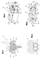
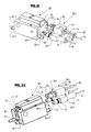
- 1 is the wiper arm of a windshield wiper system (not shown in detail) for vehicle windows (vehicle windshields).
- the wiper arm 1 consists in a known manner from a bearing element 2 which forms one end of the wiper arm 1, with which the wiper arm 1 can be fastened to a wiper shaft, not shown, of the windshield wiper system, as well as from a wiper arm element or a wiper rod 3 which has a wiper arm joint 4 the bearing element 2 is connected and forms the other end of the wiper arm 1, on which the wiper blade 5 is detachably connected to the wiper arm 1 via a wiper blade adapter 6.
- the wiper blade 5 is designed as a flat heatable wiper blade. It is in the illustrated embodiment u.a. from a profiled rail 7, which extends over the entire length of the wiper blade 5 and encloses a spring rail 8. On the rail 7 of the wiper lip 9 forming and is also held over the entire length of the wiper blade 5 extending squeegee 10.
- the wiper blade 5 is further provided with two each extending over a wiper blade longitudinal side and formed in the rail 7 distribution or injection channels 11 and 12, each having a plurality of nozzle openings 11.1 and 12.1 for dispensing a cleaning or washing liquid, for example for dispensing Have water with cleaning and / or anti-freeze additives on the vehicle window, not shown.
- a wiper blade side heating element 13 which is formed in the illustrated embodiment of a heating wire and designed such that this heating element 13 forms at least one closed electric heating circuit.
- two fluid conduits 14 are provided, e.g. are formed by two channels of a double tube.
- the heating element 13 is in the manner described in more detail below in the region of the wiper blade adapter 6 with at least one outer u.a. in the wiper arm 1 extending electrical connection line 15 in the manner described in more detail below.
- the wiper blade adapter 6 is designed in two parts, namely consisting of a wischarm brieflyen adapter part 17 and a wiper blade side, that is firmly connected to the wiper blade adapter part 18. Both adapter parts 17 and 18 are hinged together, so that the wiper blade 5 is held slightly pivotable on the wiper arm 1 ,
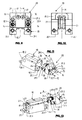
- the wiper blade-side adapter part 18 is in the FIGS. 5 to 16 shown in detail.
- the wiper arm-side adapter part 17 is formed in the illustrated embodiment by a wiper arm 1 held on the bracket which engages over the wiper blade side adapter part 18, in such a way that this adapter part 18 and the wiper blade 5 laterally provided by the wiper arm 1 are.
- the adapter part 18 is formed as a molded plastic part substantially parallelepiped-shaped and the wiper blade 5 is fastened on its upper side like a rider on this wiper blade 5, approximately in the wiper blade center.
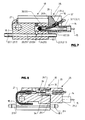
- two flow channels 20 and 21 are inter alia formed, each extending on one longitudinal side of the adapter part 18 in the adapter longitudinal direction L and ends at both ends in a connecting piece 20.1 or 21.1, via which the respective flow channel is connected to the associated injection channel, and Although the injection channel 11 with the flow channel 20 and the injection channel 12 with the flow channel 21.
- Via an adapter part internal connection 22 and 23 is each flow channel 20 and 21 with its own sleeve-like, ie formed by an opening hydraulic port or liquid port 24th or 25 in connection.
- an electrical connection 26 with two plug-type connecting elements or contact pins is furthermore provided thereon, specifically for connecting the heating element 13 to the two outer electrical connection lines 15.
- an electrically-hydraulic coupling unit 28 which essentially consists of a molding 29 made of plastic, which on a common end face 29.1 two wegumble over this end face and with their axes parallel to each other and perpendicular to the plane of the end face 29.1 oriented hollow pin-like hydraulic fittings or terminals 30, each of which fits and sealed in a port 24th or 25 is insertable.
- the port 30 is connected via an internal flow channel 32 with a connecting piece 32.1 and the terminal 31 via an internal flow channel 33 with a Anschussstutzen 33.1.
- the connecting pieces 32.1 and 33.1 project beyond the end face 29.1 facing away from the end face 29.2 of the molding 29 and are each connected to a liquid line 14.
- Above the terminals 30 and 31 is on the front side 29.1 on this end face away electrical connection 34 is provided, which is designed as a two-pin socket and that for establishing an electrical connection with the adapter part side electrical connection 26 and with the local pin-shaped electrical contacts 26.1 ,
- the connection 34 can be inserted sealed into a recess 35 of the adapter part 18, in which the pin-shaped contacts of the electrical connection 26 are received.
- the two hydraulic connections 24 and 25 and the electrical connection 26 are located on a common, freely accessible end face 18.1 of the adapter part 18, which faces a wiper blade end 5.1, ie, in the illustrated embodiment, the wiper blade end 5.1 of the wiper blade closer to the bearing element 2.
- the two hydraulic connections 24 and 25 and the electrical connection 26 are furthermore provided in such a way that the adapter part 18 is also mirror-symmetrical with respect to the spatial arrangement of the hydraulic connections 24 and 25 and the electrical connection 26 to a center plane enclosing the longitudinal extension L of the adapter part 18 M is formed.
- the arrangement of the hydraulic connections 30 and 31 and the electrical connection 34 corresponds to the arrangement of the connections 24 and 25 and the electrical connection 26, so that in a single joining operation (arrow A) the hydraulic and electrical connection of the adapter part 18 and so that the wiper blade 5 with the liquid lines 14 and the electrical lines 15 can be produced, by attaching the Coupling unit 28 on the end face 18.1 of the adapter part 18, or conversely, the hydraulic and electrical connection between the adapter part 18 and the wiper blade 5 and the liquid lines 14 and the electrical lines 15 can be separated, by removing the coupling part of the adapter part 18th
- the outer lines 15 extend within the liquid lines 14 and also within the coupling unit 28 to a contact of the electrical connection 34 in such a way that each electrical line 15 extends to the open end of the respective connection 30 or 31, then turned by 180 ° in the associated flow channel 32 and 33 led back and out of this flow channel using a seal 36 to the rear end face 29.2 of the coupling unit 28 is led out. Subsequently, each line 15 extends from the end face 29.2 using a further seal 37 to the terminal 34 and to the associated socket contact of this terminal.
- This special course of each connecting line 15 is in the FIG. 16 again shown in detail.
- the seals 36 and 37 are in the illustrated embodiment made of rubber-elastic material sleeve-like sealing elements which are elastically deformed in corresponding recesses of the coupling unit 28 and the molding 29 are used.
- coupling unit 28 When connected to the adapter part 18 coupling unit 28 is thus a closed circuit for the heating element 13 flowing through the heating current formed, via one of the outer lines 15, via the electrical connections 34 and 26, via the heating element 13 and then via the electrical connection 26 and 34 back to the other connection line 15.
- the coupling unit 28 with the adapter part 18 is at the same time also the hydraulic connection between the liquid lines 14 and the associated spray channels 11 and 12 prepared, and in particular in such a way that these spray channels 11 and 12 can be supplied via the liquid lines 14 individually with the cleaning liquid.
- the embodiment described allows a simple connection of the wiper blade 5 on the wiper arm as well as a simple replacement of the wiper blade 5 with simple manufacture and release of both the hydraulic and the electrical connection between the adapter part 18 and the coupling unit 28th
- FIGS. 17 and 18 show as a further embodiment, a coupling unit 28a, which differs from the coupling unit 28 in that the two extending in the liquid lines 14 and formed as a heating element or heating wire electrical lines 15 on the coupling unit 28a not each with an electrical contact of the electrical connection 34th but are connected directly to one another via a line section 15.1, namely at the rear end side 29.2 of the coupling unit 28a, so that for heating the liquid lines 14, a heating current flow from a vehicle-side supply unit via an electrical line designed as a heating element or heating wire to the coupling unit 28a and then over the line section 15.1 and the other line 15 back to the vehicle-side electrical supply unit is possible.
- FIG. 18 shows again schematically the course of the electrical lines 15 and 38 and the line section 15.1 in the region of the coupling unit 28a.
- the coupling unit 28a is in the same How the coupling unit 28 is connected to the adapter part 18 of the wiper blade 5.
- An additional advantage of the embodiment of FIGS. 17 and 18 is that the heating of the wiper blade 5 and the heating of the two fluid lines 14 is individually controllable.
- FIGS. 19 and 20 show an embodiment that differs from the embodiment of the FIGS. 17 and 18 differs in that the heating elements formed as electrical lines 15 in the liquid lines 14 each form an independent closed loop that extends to the open end of the respective port 30 and 31 respectively.
- the two outer lines 38 are provided which connect the electrical connection 34 and its contacts with the vehicle-side supply unit.
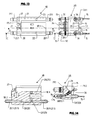
- FIGS. 21-25 show an embodiment in which for the electrical and hydraulic connection, a coupling unit 28c is provided, which is formed in two parts and consists of the two coupling elements 39 and 40.
- the coupling element 40 which is provided for the hydraulic connection or fluid connection, has on one end face 40.1 the two ports 30 and 31 and is provided on the other end face 40.2 with the connecting pieces 32.1 and 33.1, which serve to connect the liquid lines 14 and via internal flow channels 32 and 33 are each connected to one of the hydraulic coupling pieces 30 and 31.
- the coupling element 39 is provided on an end face 39.1 with the two socket contacts having electrical connection 34 which projects beyond the end face 39.1.
- the two outer supply lines 38 are led out for the operation of the heating element 13.
- the liquid lines 14 again serve as a heating element or heating wires running lines 15, which in this embodiment also form a closed loop in each liquid lines 14, which extends to the open end of each hydraulic port 30 and 31, respectively.
- the two coupling elements 39 and 40 respectively separately to connect to the adapter part 18 and to solve this adapter part.
- FIG. 26 shows again in a very simplified schematic representation of the wiper arm 1 and attached to the free end of the wiper arm wiper blade 5 with the wiper blade side heating element 13 and the operation of the heating element 13 serving outer lines 15, which in this embodiment again designed as electrical heating elements or heating wires are and in the liquid lines 14 for supplying the washing and cleaning liquid to the wiper blade 5 and to the local injection channels 11 and 12 extend.
- the two electrical lines 15 are led out of the liquid lines 14 on coupling pieces 41 and 42 and connected to a vehicle-side control device 43, via which the electrical heating element 13 and the two designed as heating or resistance wires lines 15 in the activated state controlled with a Heating current from the vehicle electrical system of the vehicle are acted upon.
- control device 43 is an on and off switch or a corresponding circuit.
- control device 43 it is also possible to form the control device 43 as a more complex unit, which then, for example, the heater 15 and the electric heating element 13 flowing through heating current and thus the heating power as a function of environmental parameters and / or operating parameters of the vehicle, for example, depending on the outside temperature and / or the vehicle speed and / or the speed of the pivoting movement of the wiper arm 1 controls or regulates.
- FIG. 26 illustrated embodiment thus corresponds to the embodiment as described above in connection with the FIGS. 5 to 16 has been described.
- the two liquid lines 14 on the vehicle side each with an output of a local, in the FIG. 26 only very schematically indicated supply unit 44 connected for the washing and cleaning liquid, in such a way that via the respective liquid line 14 each injection channel 11 or 12 of the respective wiper blade 5 also individually controlled with the washing and cleaning liquid can be supplied, for example in the Form that the cleaning and spraying liquid is applied during the wiping operation from the nozzle openings 11.1 and 12.2 the wiper blade 5 and the wiper lip 9 in advance on the vehicle window.
- FIG. 27 shows an embodiment in which the at least one electrical heating element 13 of the respective wiper blade 5 is operated via separate external electrical lines 38 and the two running in the liquid lines 14 electrical lines 15 are designed as electrical heating elements or heating or resistance wires and in the region Wiper blade 5 are connected to each other via an electrical bridge.
- the two vehicle-side ends of the electrical lines 15 and 38 are connected either to a common output or with separate outputs of the control device 43, so that in the first case, the heating of the wiper blade 5 by the heating element 13 and the heating of the liquid lines 14 by the heating element or Heating wires formed lines 15 is controlled or regulated together or in the second case, an individual control or regulation of the heating power of the heating element 13 in the wiper blade 5 and the heating element formed by the lines 15 is possible.
- This embodiment is substantially the same as that described above FIGS. 17 and 18 described embodiment.
- FIG. 28 schematically shows the liquid lines 14 for two wiper blades 5 with arranged in these liquid lines 14 and again preferably designed as a heating or resistance wire electrical leads 15.
- the one end of each pair of liquid lines 14 in this embodiment for example, each connected to a coupling unit 28, and although for connection to the provided on the respective wiper blade 5 adapter part 18, so that after the preparation of the hydraulic and electrical connection with the respective wiper blade 5, a liquid line 14 of each pair with the injection channel 11 and the other liquid line 14 of each liquid line pair with the spray channel 12 in connection stands.
- the vehicle side are the corresponding one, ie with the injection channel eleventh or connected to the injection channel 12 liquid lines 14 each connected to a common coupling piece 45 and 46, which in turn is connected via a connecting piece 45.1 and 46.1 each with an output of the vehicle-side supply unit 44 (pump) for the washing and cleaning liquid.
- the mutually corresponding and preferably in turn designed as heating elements or heating wires electrical lines 15 are led out of the respective coupling piece 45 and 46 and connected to the terminals of the vehicle-side electrical control device 43.
- FIG. 23 also corresponds to the embodiment of the FIGS. 5 to 16 in which the at least one electrical heating element 13 of the wiper blade 6 is arranged in series with the two heating elements formed by the lines 15 in the liquid lines 14.
- FIG. 29 Finally, an embodiment, which differs from the embodiment of the FIG. 28 only differs in that designed as heating elements or heating wires and extending in the liquid lines 14 electrical lines 15 in the region of the wiper blade 5, ie, for example, in the region of the local coupling unit 28a are connected to each other via a line section or wire web, so that the wires designed as heating wires 15th form electrical heating elements exclusively for heating the liquid lines 14.
- each electrical lines 38 are provided separately.
- the embodiment illustrated essentially corresponds to that in connection with FIGS FIGS. 17 and 18 described embodiment.
- FIGS. 30 and 31 Other examples of flat wiper blades show the FIGS. 30 and 31 , In the in the FIG. 30 shown in cross section flat wiper blade 5a is attached to the rail 7 a spoiler forming spoiler 46. In this spoiler profile, the two injection channels 11 and 12 are formed with the associated nozzle openings 11.1 and 12.1. In each injection channel 11 and 12 extending is again provided at least a length of the wiper blade side heating element 13 forming heating or resistance wire.
- FIG. 31 shown in cross section flat wiper blade 5b does not have the rail 7.
- this wiper blade 3b two extending over the entire length of the wiper blade spring rails 8 are provided between which the squeegee 10 is held by the fact that the spring rails 8 each engage with a portion of their width in recesses of the wiper blade 10.
- the spring rails 8 are overlapped on their protruding from the squeegee areas of a trained in this embodiment of spoiler profile 47 wiper blade element.
- the injection channels 11 and 12 are formed with the nozzle and injection openings 11.1 and 12.1.
- the wiper blade-side heating element 13 is in turn formed by lengths of a heating and resistance wire extending in the spray channels 11 and 12.
- the wiper blade-side terminals 24 and 25 or 26 on the adapter part 18 can be at least partially designed as a pin-like, on the front side 18.1 wegumble connections and the respective corresponding connection to the coupling unit 28, 28a, 28b and 28c as an opening.
- the embodiment shown in the figures has the advantage of a particularly compact design of the combination adapter part 18 and coupling unit 28, 28a, 28b and 28c, since the adapter part 18 for effective attachment to the wiper blade 5 a certain length in wiper blade longitudinal direction or in the adapter longitudinal direction L must have and thus it is easily possible to provide the terminals 24, 25 and 26 forming and extending with its axis parallel to the adapter longitudinal axis L openings in the adapter part 18.
- the heating element 13 is formed by a heating or resistance wire running in the spray channels 11 and 12.
- this heating element can also be designed as a heating foil, which is then e.g. is arranged or provided on the at least one spring rail 8 or otherwise on or in the wiper blade 5, 5a, 5b.
Description
Die Erfindung bezieht sich auf eine Wischarm/Wischblatt-Verbindung bei Scheibenwischanlagen für Fahrzeuge gemäß Oberbegriff Patentanspruch 1, auf ein Wischblatt gemäß Oberbegriff Patentanspruch 16 sowie eine Scheibenwischanlage gemäß Oberbegriff Patentanspruch 20.The invention relates to a wiper arm / wiper blade connection in windshield wiper systems for vehicles according to the preamble of
Wischblätter zur Verwendung bei Scheibenwischanlagen von Fahrzeugen sind in unterschiedlichen Ausführungen bekannt. Bekannt sind insbesondere auch flache Wischblätter (
Bekannt sind weiterhin elektrisch beheizbare Wischblätter (
"Flache Wischblätter" werden inzwischen auch als "Flachwischblätter" oder "Flachbalkenwischblätter" oder "Gelenkfreie Wischblätter" bezeichnet. Im Sinne der vorliegenden Erfindung bestehen diese flachen Wischblätter generell aus einem Wischgummi mit einer Wischlippe, wobei der Wischgummi an einer Federschiene oder an zwei Federschienen gehalten bzw. befestigt ist und an der Federschiene oder an den Federschienen eine Anschlussvorrichtung bzw. ein Wischblattadapter zum Verbinden mit einem für die Wischbewegung antreibbaren Wischarm angebracht ist. Bei nur einer Federschiene ist diese in einem Längskanal des Wischgummis angeordnet oder auf dem Rücken des Wischgummis befestigt. Bei zwei Federschienen greifen diese in Längsnuten an den gegenüberliegenden langen Außenseiten des Wischgummis ein. Bei einer weiteren generellen Ausbildung flacher Wischblätter ist der Wischgummi mit seinem Rückenteil in einem länglichen elastischen Profilkörper aufgenommen, ebenso eine Federschiene oder mehrere Federschienen. Wenn der Profilkörper selbst mit den erforderlichen Federeigenschaften versehen ist, kann auch auf zusätzliche Federschienen verzichtet werden. Die Anschlussvorrichtung zum Verbinden des Wischblattes mit dem Wischarm ist dann an diesem Profilkörper angebracht. Je nach Verwendungszweck können zusätzliche Elemente, wie Spoiler oder Heizvorrichtungen oder Elemente zur Abgabe von Waschflüssigkeit oder Ähnliches an dem Wischblatt vorgesehen oder angebracht sein."Flat wiper blades" are now also referred to as "flat wiper blades" or "flat bar wiper blades" or "joint-free wiper blades". For the purposes of the present invention, these flat wiper blades generally consist of a squeegee with a wiper lip, wherein the squeegee is held or fixed to a spring rail or two spring rails and on the spring rail or on the spring rails a connection device or a wiper blade adapter for connecting to a Wiper arm which can be driven for the wiping movement is mounted. With only one spring rail this is arranged in a longitudinal channel of the wiper blade or attached to the back of the wiper blade rubber. With two spring rails these engage in longitudinal grooves on the opposite long outer sides of the wiper blade rubber. In a further general embodiment of flat wiper blades of the squeegee is received with its back part in an elongated elastic profile body, as well as a spring rail or a plurality of spring rails. If the profile body itself is provided with the required spring properties, can be dispensed with additional spring rails. The connection device for connecting the wiper blade to the wiper arm is then attached to this profile body. Depending on the purpose, additional elements such as spoilers or heaters or elements for dispensing washing liquid or the like may be provided or attached to the wiper blade.
Gegenteilig zu den flachen Wischblättern sind die so genannten "Bügelwischblätter". Ein typisches Beispiel für Bügelwischblätter ist in der
Eine gattungsgeässe Wischarm/Wischblatt-Verbindung, ein gattungsgemässes Wischblatt und eine gattungsgemässe Scheibenwischanlage sind aus dem Dokument
Aufgabe der Erfindung ist es, eine Wischarm/Wischblatt-Verbindung aufzuzeigen, die als mechanische, hydraulische und zugleich auch elektrische Verbindung ein vereinfachtes Anschließen und Trennen eines elektrisch beheizbaren und zugleich mit Spritzdüsen zum Ausbringen einer Reinigungs- oder Waschflüssigkeit auf die Fahrzeugscheibe versehenen Wischblattes am Wischarm bzw. vom Wischarm ermöglicht. Zur Lösung dieser Aufgabe ist eine Wischblatt/Wischarm-Verbindung entsprechend dem Patentanspruch 1 ausgebildet.The object of the invention is to show a wiper arm / wiper blade connection, as a mechanical, hydraulic and at the same time electrical connection a simplified connection and disconnection of an electrically heated and at the same time provided with spray nozzles for dispensing a cleaning or washing liquid on the vehicle window wiper blade on the wiper arm or wiper arm allows. To solve this problem, a wiper blade / wiper arm connection according to the
Aufgabe der Erfindung ist weiterhin, ein Wischblatt aufzuzeigen, welches Spritzdüsen oder -öffnungen zum Ausbringen der Wasch- oder Reinigungsflüssigkeit auf die Fahrzeugscheibe aufweist, elektrisch beheizbar ist und problemlos an einem Wischarm einer Scheibenwischanlage befestigbar und von diesem abnehmbar ist. Zur Lösung dieser Aufgabe ist ein Wischblatt entsprechend dem Patentanspruch 16 ausgebildet.The object of the invention is further to show a wiper blade, which has spray nozzles or openings for discharging the washing or cleaning liquid on the vehicle window, is electrically heated and easily attachable to a wiper arm of a windscreen wiper system and can be removed therefrom. To solve this problem, a wiper blade according to
Aufgabe der Erfindung ist weiterhin auch, eine Scheibenwischanlage mit wenigstens einem beheizbaren und Spritzdüsen oder -Öffnungen zum Ausbringen der Wasch- oder Reinigungsflüssigkeit auf die Fahrzeugscheibe aufweisenden Wischblatt aufzuzeigen, welches problemlos an einem Wischarm einer Scheibenwischanlage befestigbar und von diesem abnehmbar ist, wobei vorzugsweise mit einfachen Mitteln zugleich auch ein Beheizen der wenigstens einen Versorgungs- oder Flüssigkeitsleitung für die Reinigungs- oder Waschflüssigkeit erreicht ist. Zur Lösung dieser Aufgabe ist eine Scheibenwischanlage entsprechend dem Patentanspruch 20 ausgebildet.The object of the invention is also to show a windshield wiper system with at least one heated and spray nozzles or openings for discharging the washing or cleaning liquid on the vehicle window having wiper blade, which is easily attachable to a wiper arm of a windscreen wiper system and removable from this, preferably with simple Means at the same time also a heating of the at least one supply or liquid line for the cleaning or Washing liquid is reached. To solve this problem, a windscreen wiper system according to
Weiterbildungen, Vorteile und Anwendungsmöglichkeiten der Erfindung ergeben sich auch aus der nachfolgenden Beschreibung von Ausführungsbeispielen und aus den Figuren. Dabei sind alle beschriebenen und/oder bildlich dargestellten Merkmale für sich oder in beliebiger Kombination grundsätzlich Gegenstand der Erfindung, unabhängig von ihrer Zusammenfassung in den Ansprüchen oder deren Rückbeziehung. Auch wird der Inhalt der Ansprüche zu einem Bestandteil der Beschreibung gemacht.Further developments, advantages and applications of the invention will become apparent from the following description of exemplary embodiments and from the figures. In this case, all described and / or illustrated features alone or in any combination are fundamentally the subject of the invention, regardless of their summary in the claims or their dependency. Also, the content of the claims is made an integral part of the description.
Die Erfindung wird im Folgenden anhand der Figuren an Ausführungsbeispielen erläutert. Es zeigen:
- Fig. 1
- in perspektivischer Darstellung den Wischarm einer Scheibenwischanlage für Fahrzeuge, zusammen mit dem am Wischarm lösbar befestigten flachen Wischblatt;
- Fig. 2
- eine Darstellung wie
Figur 1 - Fig. 3
- in vereinfachter Darstellung einen Schnitt durch das flache Wischblatt der
Figuren 1 und 2 - Fig. 4
- einen Schnitt durch den Wischarm bzw. durch die Wischstange des Wischarmes der
Figuren 1 und 2 - Fig. 5
- in perspektivischer Darstellung das wischblattseitige Adapterteil des Wischblattadapters, zusammen mit einer elektrisch-hydraulischen Kupplungseinheit;
- Fig. 6
- eine Draufsicht auf die Anordnung der
Figur 5 - Fig. 7 und 8
- Schnitte entsprechend der Schnittlinien A - A bzw. B - B der
Figur 6 - Fig. 9 und 10
- das wischblattseitige Adapterteil in unterschiedlichen Stirnansichten;
- Fig. 11 und 12
- in unterschiedlichen perspektivischen Ansichten das wischblattseitige Adapterteil zusammen mit der von diesem Adapterteil abgenommenen Kupplungseinheit;
- Fig. 13
- eine Draufsicht auf die Anordnung der
Figuren 11 - Fig. 14 und 15
- Schnitte entsprechend der Schnittlinie C - C bzw. D - D der
Figur 13 - Fig. 16
- in schematischer perspektivischer Darstellung den Verlauf einer elektrischen, von einem Heizdraht gebildeten Anschlussleitung innerhalb der Kupplungseinheit;
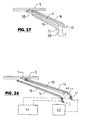
- Fig. 17
- in perspektivischer Einzeldarstellung die elektrisch-hydraulische Kupplungseinheit bei einer weiteren Ausführungsform der Erfindung;
- Fig. 18
- in einer Darstellung ähnlich
Figur 16 den Verlauf der elektrischen, von einem Widerstandsdraht gebildeten Anschluss-Leitung in der Kupplungseinheit derFigur 17 ; - Fig. 19
und 20 Darstellungen wie Figuren 17 und 18 bei einer weiteren Ausführungsform der Erfindung;- Fig. 21
und 22 - in unterschiedlichen perspektivischen Darstellungen das wischblattseitige Adapterteil zusammen mit einer elektrischen und hydraulischen Kupplungseinheit bei einer weiteren Ausführungsform der Erfindung;
- Fig. 23
- eine Draufsicht auf die
Anordnung der Figuren 21 ;und 22 - Fig. 24
und 25 - Schnitte entsprechend den Linien E - E bzw. F -
F der Figur 23 ; - Fig. 26 - 29
- jeweils in schematischer Darstellung den Verlauf der elektrischen Anschluss-Leitungen und den Anschluss des wischblattseitigen Heizelementes bei unterschiedlichen Ausführungsformen der Erfindung;
- Fig. 30
und 31 - Schnitte durch weitere flache Wischblätter.
- Fig. 1
- in a perspective view of the wiper arm of a windscreen wiper system for vehicles, together with the wiping arm detachably attached to the flat wiper blade;
- Fig. 2
- a representation like
FIG. 1 but with the cover removed, in the region of the wiper blade adapter connecting the wiper blade to the wiper arm; - Fig. 3
- in a simplified representation of a section through the flat wiper blade of
Figures 1 and 2 ; - Fig. 4
- a section through the wiper arm or by the wiper rod of the wiper arm of
Figures 1 and 2 ; - Fig. 5
- in a perspective view of the wiper blade side adapter part of the wiper blade adapter, together with an electric-hydraulic coupling unit;
- Fig. 6
- a plan view of the arrangement of
FIG. 5 ; - FIGS. 7 and 8
- Sections corresponding to the section lines A - A and B - B of
FIG. 6 ; - FIGS. 9 and 10
- the wiper blade side adapter part in different end views;
- FIGS. 11 and 12
- in different perspective views of the wiper blade side adapter part together with the detached from this adapter part coupling unit;
- Fig. 13
- a plan view of the arrangement of
Figures 11 or 12; - FIGS. 14 and 15
- Cuts according to the section line C - C or D - D of the
FIG. 13 ; - Fig. 16
- in a schematic perspective view of the course of an electrical connecting line formed by a heating wire within the coupling unit;
- Fig. 17
- in a perspective single representation of the electric-hydraulic coupling unit in a further embodiment of the invention;
- Fig. 18
- similar in a presentation
FIG. 16 the course of the electrical, formed by a resistance wire connection line in the coupling unit ofFIG. 17 ; - FIGS. 19 and 20
- Depictions like
FIGS. 17 and 18 in another embodiment of the invention; - FIGS. 21 and 22
- in different perspective views of the wiper blade side adapter part together with an electrical and hydraulic coupling unit in a further embodiment of the invention;
- Fig. 23
- a plan view of the arrangement of
FIGS. 21 and 22 ; - FIGS. 24 and 25
- Sections corresponding to lines E - E and F - F of
FIG. 23 ; - FIGS. 26-29
- in each case a schematic representation of the course of the electrical connection lines and the connection of the wiper blade side heating element in different embodiments of the invention;
- FIGS. 30 and 31
- Cut through more flat wiper blades.
In den Figuren ist 1 der Wischarm einer ansonsten nicht weiter dargestellten Scheibenwischanlage für Fahrzeugscheiben (Fahrzeugfrontscheiben). Der Wischarm 1 besteht in bekannter Weise aus einem das eine Ende des Wischarmes 1 bildenden Lagerelement 2, mit dem der Wischarm 1 an einer nicht dargestellten Wischwelle der Scheibenwischanlage befestigt werden kann, sowie aus einem Wischarmelement oder einer Wischstange 3, die über ein Wischarmgelenk 4 mit dem Lagerelement 2 verbunden ist und das andere Ende des Wischarmes 1 bildet, an dem das Wischblatt 5 über einen Wischblattadapter 6 lösbar mit dem Wischarm 1 verbunden ist.In the figures, 1 is the wiper arm of a windshield wiper system (not shown in detail) for vehicle windows (vehicle windshields). The
Das Wischblatt 5 ist als flaches beheizbares Wischblatt ausgeführt. Es besteht bei der dargestellten Ausführungsform u.a. aus einer Profilschiene 7, die sich über die gesamte Länge des Wischblattes 5 erstreckt und eine Federschiene 8 umschließt. An der Profilschiene 7 ist der die Wischlippe 9 bildende und sich ebenfalls über die gesamte Länge des Wischblattes 5 erstreckende Wischgummi 10 gehalten. Das Wischblatt 5 ist weiterhin mit zwei sich jeweils über eine Wischblattlängsseite erstreckenden und in der Profilschiene 7 ausgebildeten Verteiler- oder Spritzkanäle 11 und 12 versehen, die jeweils eine Vielzahl von Düsenöffnungen 11.1 bzw. 12.1 zum Ausbringen einer Reinigungs- oder Waschflüssigkeit, beispielsweise zum Ausbringen von Wasser mit Reinigungs- und/oder Frostschutzzusätzen auf die nicht dargestellte Fahrzeugscheibe aufweisen.The
Innerhalb der Spritzkanäle 11 und 12 erstreckt sich ein wischblattseitiges Heizelement 13, welches bei der dargestellten Ausführungsform von einem Heizdraht gebildet und derart ausgeführt ist, dass dieses Heizelement 13 wenigstens einen geschlossenen elektrischen Heizstromkreis bildet.Within the
Die Versorgung der Spritzkanäle 11 und 12 mit der Spritz- und Reinigungsflüssigkeit erfolgt über im Wischarm 1 verlegte und von Schlauchleitungen gebildete Flüssigkeitsleitungen 14 mit denen die Spritzkanäle 11 und 12 jeweils im Bereich des Wischblattadapters 6 in der nachstehend noch beschriebenen Weise verbunden sind. Bei der dargestellten Ausführungsform sind zwei Flüssigkeitsleitungen 14 vorgesehen, die z.B. von zwei Kanälen eines Doppelschlauchs gebildet sind. Das Heizelement 13 ist in der nachstehend noch näher beschriebenen Weise im Bereich des Wischblattadapters 6 mit wenigstens einer äußeren u.a. im Wischarm 1 verlaufenden elektrischen Anschlussleitung 15 in der nachstehend noch näher beschriebenen Weise verbunden.The supply of the
Bei am Wischarm 1 montiertem Wischblatt 5 ist der Wischblattadapter 6 durch eine Blende 16 abgedeckt.When mounted on the
Der Wischblattadapter 6 ist zweiteilig ausgeführt, und zwar bestehend aus einem wischarmseitigen Adapterteil 17 und einem wischblattseitigen, d.h. mit dem Wischblatt fest verbundenem Adapterteil 18. Beide Adapterteile 17 und 18 sind gelenkig miteinander verbunden, so dass das Wischblatt 5 leicht schwenkbar am Wischarm 1 gehalten ist. Das wischblattseitige Adapterteil 18 ist in den
Im Bereich der Oberseite des Adapterteils 18 ist an diesem weiterhin ein elektrischer Anschluss 26 mit zwei steckerartigen Anschlusselementen oder Kontaktstiften vorgesehen, und zwar zum Verbinden des Heizelementes 13 mit den beiden äußeren elektrischen Anschluss-Leitungen 15. Über adapterteilinterne elektrische Verbindungen 27 sind der Anschluss 26 bzw. dessen steckerartige Anschlusselemente mit dem Heizelement 13 verbunden.In the area of the upper side of the
Für den elektrischen und hydraulischen Anschluss des Adapterteils 18 bzw. des Wischblattes 5 an die Flüssigkeitsleitungen 14 und die elektrischen Leitungen 15 dient eine elektrisch-hydraulische Kupplungseinheit 28, die im Wesentlichen aus einem Formteil 29 aus Kunststoff besteht, welches an einer gemeinsamen Stirnseite 29.1 zwei über diese Stirnseite wegstehende und mit ihren Achsen parallel zueinander sowie senkrecht zur Ebene der Stirnseite 29.1 orientierte hohlzapfenartige hydraulische Anschlusstücke oder Anschlüsse 30 aufweist, von denen jeder passend und abgedichtet in einen Anschluss 24 bzw. 25 einführbar ist. Der Anschluss 30 ist dabei über einen internen Strömungskanal 32 mit einem Anschlussstutzen 32.1 und der Anschluss 31 über einen internen Strömungskanal 33 mit einem Anschussstutzen 33.1 verbunden. Die Anschlussstutzen 32.1 und 33.1 stehen über die der Stirnseite 29.1 abgewandte Stirnseite 29.2 des Formteils 29 weg und sind jeweils mit einer Flüssigkeitsleitung 14 verbunden. Oberhalb der Anschlüsse 30 und 31 ist an der Stirnseite 29.1 ein über diese Stirnseite weg stehender elektrischer Anschluss 34 vorgesehen, welcher als zweipolige Buchse ausgebildet ist und zwar zur Herstellung einer elektrischen Verbindung mit dem adapterteilseitigen elektrischen Anschluss 26 bzw. mit den dortigen stiftförmigen elektrischen Kontakten 26.1. Der Anschluss 34 ist hierfür in eine Ausnehmung 35 des Adapterteils 18 abgedichtet einführbar, in der die stiftförmigen Kontakte des elektrischen Anschlusses 26 aufgenommen sind.For the electrical and hydraulic connection of the
Die beiden hydraulischen Anschlüsse 24 und 25 sowie der elektrische Anschluss 26 befinden sich an einer gemeinsamen, frei zugänglichen Stirnseite 18.1 des Adapterteils 18, die einem Wischblattende 5.1 zugewandt ist, d.h. bei der dargestellten Ausführungsform dem dem Lagerelement 2 näher liegenden Wischblattende 5.1 des Wischblattes 5. Die beiden hydraulischen Anschlüsse 24 und 25 sowie der elektrische Anschluss 26 sind weiterhin derart vorgesehen, dass das Adapterteil 18 auch in Bezug auf die räumliche Anordnung der hydraulischen Anschlüsse 24 und 25 sowie des elektrischen Anschlusses 26 spiegelsymmetrisch zu einer die Längserstreckung L des Adapterteils 18 einschließenden Mittelebene M ausgebildet ist. Es versteht sich, dass die Anordnung der hydraulischen Anschlüsse 30 und 31 und des elektrischen Anschlusses 34 der Anordnung der Anschlüsse 24 und 25 sowie des elektrischen Anschlusses 26 entspricht, sodass in einem einzigen Fügevorgang (Pfeil A) die hydraulische und elektrische Verbindung des Adapterteils 18 und damit des Wischblattes 5 mit den Flüssigkeitsleitungen 14 und den elektrischen Leitungen 15 herstellbar ist, und zwar durch Aufstecken der Kupplungseinheit 28 auf die Stirnseite 18.1 des Adapterteils 18, oder umgekehrt die hydraulische sowie elektrische Verbindung zwischen dem Adapterteil 18 bzw. dem Wischblatt 5 und den Flüssigkeitsleitungen 14 sowie den elektrischen Leitungen 15 getrennt werden kann, und zwar durch Abziehen des Kupplungsteils vom Adapterteils 18The two
Bei der in den
Bei der dargestellten Ausführungsform sind die elektrischen Anschlussleitungen 15, die fahrzeugseitig über eine Steuereinheit mit einer elektrischen Spannungs- oder Stromquelle verbunden sind, als Heizelemente ausgeführt und bestehen hierfür im einfachsten Fall jeweils aus einem Heiz- oder Widerstandsdraht, sodass beim Beheizen des Wischblattes 5, d.h. beim Aktivieren des dortigen Heizelementes 13 zugleich auch ein Beheizen der Flüssigkeitsleitungen 14 sowie der Kupplungseinheit 28 und des Adapterteils 18 bzw. der dortigen Flüssigkeitskanäle auf ihrer gesamten Länge erfolgt.In the illustrated embodiment, the
Bei mit dem Adapterteil 18 verbundenem Kupplungseinheit 28 ist somit ein geschlossener Stromkreis für den das Heizelement 13 durchfließenden Heizstrom gebildet, und zwar über eine der äußeren Leitungen 15, über die elektrischen Anschlüsse 34 und 26, über das Heizelement 13 und anschließend über die elektrischen Anschlusses 26 und 34 zurück an die andere Anschlussleitung 15. Nach dem Verbinden der Kupplungseinheit 28 mit dem Adapterteil 18 ist zugleich auch die hydraulische Verbindung zwischen den Flüssigkeitsleitungen 14 und den zugehörigen Spritzkanälen 11 und 12 hergestellt, und zwar insbesondere auch in der Weise, dass diese Spritzkanäle 11 und 12 über die Flüssigkeitsleitungen 14 individuell mit der Reinigungsflüssigkeit versorgt werden können.When connected to the
Die beschriebene Ausführung gestattet ein einfaches Verbinden des Wischblattes 5 am Wischarm sowie auch ein einfaches Austauschen des Wischblattes 5 bei einfachem Herstellen und Lösen sowohl der hydraulischen als auch der elektrischen Verbindung zwischen dem Adapterteil 18 und der Kupplungseinheit 28.The embodiment described allows a simple connection of the
Die
Die
Die
Das Kupplungselement 39 ist an einer Stirnseite 39.1 mit dem die beiden Buchsenkontakte aufweisenden elektrischen Anschluss 34 versehen, welcher über die Stirnseite 39.1 vorsteht. An der anderen, gegenüberliegenden Stirnseite 39.2 sind aus dem Kupplungselement abgedichtet die beiden äußeren Versorgungsleitungen 38 für den Betrieb des Heizelementes 13 herausgeführt. Zum Beheizen der Flüssigkeitsleitungen 14 dienen wiederum die als Heizelement oder Heizdrähte ausgeführten Leitungen 15, die bei dieser Ausführungsform ebenfalls in jeder Flüssigkeitsleitungen 14 eine geschlossene Schlaufe bilden, die bis an das offene Ende jedes hydraulischen Anschlusses 30 bzw. 31 reicht. Abweichend von den vorstehend beschriebenen Ausführungsformen ist es bei der in den
Die
Über die Kupplungsstücke 41 und 42 sind die beiden Flüssigkeitsleitungen 14 fahrzeugseitig mit jeweils einem Ausgang einer dortigen, in der
Die
Allen zuvor beschriebenen Ausführungsformen ist gemeinsam, dass über die jeweilige Kupplungseinheit 28, 28a, 28b bzw. 28c sowohl eine wieder lösbare hydraulische Verbindung zum Zuführen der Wasch- und Reinigungsflüssigkeit an die Spritzkanäle 11 und 12 des jeweiligen Wischblattes 5, als auch eine wieder lösbare elektrische Verbindung zum Betrieb des jeweiligen Heizelementes 13 im Wischblatt 5 in einfacher Weise realisierbar ist. Allen zuvor beschriebenen Ausführungsformen ist weiterhin auch gemeinsam, dass die mit der Kupplungseinheit 28, 28a, 28b bzw. 28c zusammen wirkenden wischblattseitigen hydraulische Anschlüsse 24 und 25 sowie der wischblattseitige elektrische Anschluss 26 an dem unmittelbar am Wischblatt 5 montierten Adapterteil 18 vorgesehen sind, und zwar an der Stirnseite 18.1 dieses Adapterteils.All previously described embodiments have in common that on the
Die Erfindung wurde vorstehend der einfacheren Darstellung wegen jeweils zusammen mit einem einzigen, an einem Wischarm 1 befestigten Wischblatt 5 beschrieben. In der Regel weisen aber Scheibenwischanlagen für Fahrzeuge und dabei insbesondere für Straßenfahrzeuge jeweils wenigstens zwei Wischarme 1 mit jeweils einem Wischblatt 5 auf. Hierbei ist es dann notwendig, beide Wischblätter 5 mit den Spritzkanälen 11 und 12 auszubilden und die Spritzkanäle beider Wischblätter über am jeweiligen Wischarm verlaufende Flüssigkeitsleitungen 14 mit der fahrzeugseitigen Versorgungseinheit für die Wasch- und Reinigungsflüssigkeit zu verbinden. Ist dann auch ein elektrisches Beheizen der Wischblätter 5 erwünscht, so ist es weiterhin notwendig, das jeweils wenigstens eine elektrische Heizelement 13 jedes Wischblattes über die in den Flüssigkeitsleitungen 14 verlaufenden elektrischen Leitungen 15 oder aber über die gesonderten äußeren Leitungen 38 mit der fahrzeugseitigen elektrischen Steuereinrichtung, beispielsweise mit der Steuereinrichtung 43 zu verbinden, und zwar z.B. wiederum über die mit dem jeweiligen Adapterteil 18 des jeweiligen Wischblattes 5 zusammenwirkende Kupplungseinheit 28, 28a, 28b bzw. 28c.The invention has been described above for ease of illustration, each together with a single, attached to a
Die
Die Ausführungsform der
Die
Weitere Beispiele für flache Wischblätter zeigen die
Das in der
Die Erfindung wurde voranstehend an Ausführungsbeispielen beschrieben. Es versteht sich, dass zahlreiche Änderungen sowie Abwandlungen möglich sind, ohne dass dadurch der der Erfindung zugrundeliegende Erfindungsgedanke verlassen wird. So sind bei den vorstehend beschriebenen Ausführungsformen die hydraulischen Anschlüsse 30 und 31 sowie der elektrische Anschluss 34 an der jeweiligen Kupplungseinheit 28, 28a, 28b bzw. 28c als über die Stirnseite 29.1 dieser Kupplungseinheit zapfenartig wegstehende Elemente ausgeführt, während die wischblattseitigen hydraulischen Anschlüsse 24 und 25 und der dortige elektrische Anschluss 26 von jeweils einer Öffnung gebildet sind. Selbstverständlich ist es auch möglich, die wischblattseitigen Anschlüsse 24 und 25 bzw. 26 am Adapterteil 18 zumindest teilweise als zapfenartige, über die Stirnseite 18.1 wegstehende Anschlüsse und den jeweils entsprechenden Anschluss an der Kupplungseinheit 28, 28a, 28b bzw. 28c als Öffnung auszuführen. Die in den Figuren dargestellte Ausführung hat allerdings den Vorteil einer besonders kompakten Ausbildung der Kombination Adapterteil 18 und Kupplungseinheit 28, 28a, 28b bzw. 28c, da das Adapterteil 18 für eine wirksame Befestigung am Wischblatt 5 eine gewisse Länge in Wischblattlängsrichtung bzw. in Adapterteillängsrichtung L aufweisen muss und es hierdurch problemlos möglich ist, die die Anschlüsse 24, 25 sowie 26 bildenden und sich mit ihrer Achse parallel zur Adapterteillängsachse L erstreckenden Öffnungen im Adapterteil 18 vorzusehen.The invention has been described above by means of exemplary embodiments. It is understood that numerous changes and modifications are possible without thereby departing from the inventive concept underlying the invention. Thus, in the embodiments described above, the
Vorstehend wurde davon ausgegangen, dass das Heizelement 13 von einem in den Spritzkanälen 11 und 12 verlaufenden Heiz- oder Widerstandsdraht gebildet ist. Grundsätzlich kann dieses Heizelement auch als Heizfolie ausgebildet sein, die dann z.B. auf der wenigstens einen Federschiene 8 oder anderweitig am oder im Wischblatt 5, 5a, 5b angeordnet bzw. vorgesehen ist.It has been assumed above that the
Claims (33)
- Wiper arm/wiper blade connection between a wiper blade (5, 5a, 5b) and a wiper arm (1) of a windscreen wiper installation for vehicles, having a wiper blade adapter (6), provided on the wiper blade (5, 5a, 5b), for detachably fastening the wiper blade (5, 5a, 5b) to the wiper arm (1), wherein the wiper blade (5, 5a, 5b) is embodied as a flat wiper blade (5, 5a, 5b) and has, on at least one wiper blade longitudinal side, at least one nozzle opening (11.1, 12.1) or at least one spray duct or distributor duct (11, 12) with nozzle openings (11.1, 12.1) for discharging a cleaning fluid or washing fluid onto a vehicle windscreen, and having at least one adapter-side fluid connection (24, 25) on the wiper blade adapter (6) for detachably connecting the at least one nozzle opening (11.1, 12.1) or the at least one spray duct or distributor duct (11, 12) to at least one outer fluid line (14) for feeding the washing fluid or cleaning fluid, specifically via a coupling unit (28, 28a-28c) which is connected to the at least one fluid line (14), characterized in that the wiper blade (5, 5a, 5b) is embodied as an electrically heatable wiper blade, and
the wiper blade adapter (6) also has, in addition to the at least one fluid connection (24, 25), at least one electrical connection (26) which is detachably connected via the coupling unit (28, 28a-28c) to at least one outer electrical line (15, 38) for feeding a heating current to the wiper blade (5, 5a, 5b). - Connection according to Claim 1, characterized in that the wiper blade adapter (6) is embodied at least in two parts with a wiper-arm-side adapter part which is fastened to the wiper arm (1) and with a wiper-blade-side adapter part (18) which is fastened to the wiper blade (5, 5a, 5b), and in that the at least one adapter-side fluid connection (24, 25) and the at least one electrical connection (26) are provided on the wiper-blade-side adapter part (18).
- Connection according to Claim 1 or 2, characterized in that the fluid connections (24, 25; 30, 31) and the electrical connections (26; 34) are embodied as plug-like connections and socket-like connections,
and/or
in that at least two fluid connections (24, 25; 30, 31) which are assigned to one another are provided on the wiper-blade adapter (6) and/or at least one electrical connection (26, 34), which is at least unipolar, is provided on the coupling unit (28, 28a-28c). - Connection according to one of the preceding claims, characterized in that the at least one adapter-side fluid connection (24, 25) and the at least one adapter-side electrical connection (26) as well as the coupling unit (28, 28a-28c) which is connected to the wiper blade adapter (6) are provided on an end side (18.1), facing a wiper blade end (5.1), of the wiper blade adapter (6) or of the wiper-blade-side adapter part (18).
- Connection according to one of the preceding claims, characterized in that, when there are at least two outer fluid lines (14), the coupling unit (28, 28a-28c) has a fluid connection (30, 31) for each fluid line (14), and in that each fluid connection (30, 31) on the coupling unit (28, 28a-28c) is assigned an independent fluid connection (24, 25), connected to a spray duct or distributor duct (11, 12), on the wiper blade adapter (6).
- Connection according to one of the preceding claims, characterized in that the at least one electrical line (15) for feeding the heating current to the wiper blade (5, 5a, 5b) or to an electrical heating element (13) there runs inside the at least one fluid line (14) and is preferably embodied there at least over a partial length as a heating element, for example as a heating wire or resistance wire.
- Connection according to Claim 7, characterized in that, when there are at least two fluid lines (14), at least two outer electrical lines (15) are each provided inside a fluid line (14), and in that preferably at least one electrical line (15) is embodied at least over a partial length as a heating element, for example as a heating wire or resistance wire for heating the fluid lines (14).
- Connection according to one of the preceding claims, characterized by at least one electrical line (38), running outside the at least one fluid line (14), for feeding the heating current to the heatable wiper blade (5, 5a, 5b).
- Connection according to one of the preceding claims, characterized in that an electrical heating element which is formed by at least one length of a heating wire (15) is provided in the at least one fluid line (14).
- Connection according to one of the preceding claims, characterized in that the heating wire (15) or the heating element which is formed thereby extends over the entire length of the respective fluid line (14) between the coupling unit (28, 28a-28c) and a vehicle-side coupling piece (41, 42; 45, 46) to which the heating wire (15) or the heating element or else an electrical connection for this heating element is led out of the fluid line (14).
- Connection according to one of the preceding claims, characterized in that the at least one heating wire (15) forms, in at least one fluid line (14), at least one heating loop, specifically with a heating wire section which leads to the wiper blade (5, 5a, 5b) or to the coupling unit (28, 28a-28c), and with at least one heating wire section which leads away from the wiper blade (5, 5a, 5b) or the coupling unit (28, 28a-28c).
- Connection according to Claim 11, characterized in that the at least one heating wire section which leads in and the at least one heating wire section which leads away are provided in two different fluid lines (14) and are electrically connected to one another in the region of the wiper blade (5, 5a, 5b) or at the coupling unit (28, 28a-28c), and/or the at least one heating wire section which leads in and the at least one heating wire section which leads away run in the same fluid line (14).
- Connection according to one of the preceding claims, characterized in that when there at least two wiper arms (1), each with at least one wiper blade (5, 5a, 5b) which is provided with at least two spray ducts or distributor ducts (11, 12) and is embodied as a heatable wiper blade, each wiper blade (5, 5a, 5b) or the wiper blade adapter (6) thereof is connected to two separate fluid lines (14), and in that the electrical line (15) which forms the heating wire or the heating element is provided in each fluid line (14).
- Connection according to one of the preceding claims, characterized in that the fluid lines (14) which lead to the wiper blades (5, 5a, 5b) form at least two groups with at least two fluid lines (14), and in that the electrical lines (15) which run in a first fluid line (14) of the groups are led out of the fluid lines (14) at a first common vehicle-side coupling piece (45), and the electrical lines (15), which run in the second fluid line (14), of the groups are led out of the fluid lines (14) at a second common vehicle-side coupling piece (46).
- Connection according to one of the preceding claims, characterized in that the at least one fluid line (14) and/or the at least one outer electrical line (15, 38) are provided running over at least a partial length on the wiper arm (1).
- Wiper blade for windscreen wiper installations in vehicles, having a wiper blade adapter (6) provided on the wiper blade (5, 5a, 5b), for detachably fastening the wiper blade (5, 5a, 5b) to a wiper arm (1), wherein the wiper blade (5, 5a, 5b) is embodied as a flat wiper blade (5, 5a, 5b) and has, on at least one wiper blade longitudinal side, at least one nozzle opening or at least one spray duct or distributor duct (11, 12) with nozzle openings (11.1, 12.1) for discharging a cleaning fluid or washing fluid onto a vehicle windscreen, and having at least one adapter-side fluid connection (24, 25) on the wiper blade adapter (6) for detachably connecting the at least one nozzle opening (11.1, 12.1) or the at least one spray duct or distributor duct (11, 12) to at least one outer fluid line (14) for feeding the washing fluid or cleaning fluid, characterized in that the wiper blade (5, 5a, 5b) is embodied as an electrically heatable wiper blade, and the wiper blade adapter (6) also has, in addition to the at least one fluid connection (24, 25), at least one electrical connection (26) for detachably connecting to at least one outer electrical line (15, 38) for feeding a heating current to the wiper blade (5, 5a, 5b).
- Wiper blade according to Claim 16, characterized in that the wiper blade adapter (6) is embodied at least in two parts with a wiper-arm-side adapter part which is fastened to the wiper arm (1) and with a wiper-blade-side adapter part (18) which is fastened to the wiper blade (5, 5a, 5b), and in that the at least one adapter-side fluid connection (24, 25) and the at least one electrical connection (26) are provided on the wiper-blade-side adapter part (18).
- Wiper blade according to Claim 16 or 17, characterized in that the at least one fluid connection (24, 25) and the at least one electrical connection (26) are embodied as plug-like or socket-like connections and/or are provided on an end side (18.1), facing a wiper blade end (5.1), of the wiper blade adapter (6) or of the wiper-blade-side adapter part (18).
- Wiper blade according to one of Claims 16-18, characterized in that at least two fluid connections (24, 25) and/or at least one at least unipolar electrical connection (26) are provided on the wiper blade adapter (6).
- Windscreen wiper installation for vehicles, having at least one wiper arm (1) and one wiper blade (5, 5a, 5b) which is detachably connected to the wiper arm (1) via a wiper arm/wiper blade connection which has a wiper blade adapter (6), wherein the wiper blade (5, 5a, 5b) is embodied as a flat wiper blade (5, 5a, 5b) and has, on at least one wiper blade longitudinal side, at least one nozzle opening or at least one spray duct or distributor duct (11, 12) with nozzle openings (11.1, 12.1) for discharging a cleaning fluid or washing fluid onto a vehicle windscreen, and having at least one adapter-side fluid connection (24, 25) on the wiper blade adapter (6) for detachably connecting the at least one nozzle opening (11.1, 12.1) or the at least one spray duct or distributor duct (11, 12) to at least one outer fluid line (14) for feeding the washing fluid or cleaning fluid, characterized in that the wiper blade (5, 5a, 5b) is embodied as an electrically heatable wiper blade, and the wiper blade adapter (6) also has, in addition to the at least one fluid connection (24, 25), at least one electrical connection (26) which is detachably connected to at least one outer electrical line (15, 38) for feeding a heating current to the wiper blade (5, 5a, 5b).
- Windscreen wiper installation according to Claim 20, characterized in that the wiper blade adapter (6) is embodied at least in two parts with a wiper-arm-side adapter part which is fastened to the wiper arm (1) and with a wiper-blade-side adapter part (18) which is fastened to the wiper blade (5, 5a, 5b), and in that the at least one adapter-side fluid connection (24, 25) and the at least one electrical connection (26) are provided on the wiper-blade-side adapter part (18).
- Windscreen wiper installation according to Claim 20 or 21, characterized in that the at least one adapter-side fluid connection (24, 25) and the at least one adapter-side electrical connection (26) are provided on an end side (18.1), facing a wiper blade end (5.1), of the wiper blade adapter (6) or of the wiper-blade-side adapter part (18).
- Windscreen wiper installation according to one of Claims 20-22, characterized in that the at least one electrical line (15) for feeding the heating current to the wiper blade (5, 5a, 5b) or to an electrical heating element (13) there runs inside the at least one fluid line (14) and is preferably embodied there at least over a partial length as a heating element, for example as a heating wire or resistance wire.
- Windscreen wiper installation according to Claim 23, characterized in that, when there are at least two fluid lines (14), at least two outer electrical lines (15) are each provided inside a fluid line (14), and in that preferably at least one electrical line (15) is embodied at least over a partial length as a heating element, for example as a heating wire or resistance wire for heating the fluid lines (14).
- Windscreen wiper installation according to one of Claims 20-24, characterized by at least one electrical line (38), running outside the at least one fluid line (14), for feeding the heating current to the heatable wiper blade (5, 5a, 5b).
- Windscreen wiper installation according to one of Claims 20-25, characterized in that an electrical heating element which is formed by at least one length of a heating wire (15) is provided in the at least one fluid line (14).
- Windscreen wiper installation according to one of Claims 20-26, characterized in that the heating wire (15) or the heating element which is formed thereby extends over the entire length of the respective fluid line (14) between the coupling unit (28, 28a-28c) and a vehicle-side coupling piece (41, 42; 45, 46) to which the heating wire (15) or the heating element or else an electrical connection for this heating element is led out of the fluid line (14).
- Windscreen wiper installation according to one of Claims 20-27, characterized in that the at least one heating wire (15) forms, in at least one fluid line (14), at least one heating loop, specifically with a heating wire section which leads to the wiper blade (5, 5a, 5b) or to the coupling unit (28, 28a-28c), and with at least one heating wire section which leads away from the wiper blade (5, 5a, 5b) or the coupling unit (28, 28a-28c).
- Windscreen wiper installation according to Claim 28, characterized in that the heating wire section which leads in and the heating wire section which leads away are provided in two different fluid lines (14) and are electrically connected to one another in the region of the wiper blade (5, 5a, 5b) or at the coupling unit (28, 28a-28c), and/or the at least two heating wire sections of the at least one heating loop run in the same fluid line (14).
- Windscreen wiper installation according to one of Claims 20-29, characterized in that when there at least two wiper arms (1), each with at least one wiper blade (5, 5a, 5b) which is provided with at least two spray ducts or distributor ducts (11, 12) and is embodied as a heatable wiper blade, each wiper blade (5, 5a, 5b) or the wiper blade adapter (6) thereof is connected to two separate fluid lines (14), and in that the electrical line (15) which forms the heating wire or the heating element is provided in each fluid line (14).
- Windscreen wiper installation according to one of Claims 20-30, characterized in that the fluid lines (14) which lead to the wiper blades (5, 5a, 5b) form at least two groups with at least two fluid lines (14), and in that the electrical lines (15) which run in a first fluid line (14) of the groups are led out of the fluid lines (14) at a first common vehicle-side coupling piece (45), and the electrical lines (15), which run in the second fluid line (14), of the groups are led out of the fluid lines (14) at a second common vehicle-side coupling piece (46).
- Windscreen wiper installation according to one of Claims 20-31, characterized in that the at least one fluid line (14) and/or the at least one outer electrical line (15, 38) are provided running over at least a partial length on the wiper arm (1).
- Windscreen wiper installation according to one of Claims 20-32, characterized in that the wiper arm/wiper blade connection is embodied according to one of Claims 1-15.
Priority Applications (1)
| Application Number | Priority Date | Filing Date | Title |
|---|---|---|---|
| PL09740052T PL2331371T3 (en) | 2008-09-26 | 2009-09-21 | Wiper arm/wiper blade connection, wiper blade and windscreen wiper installation |
Applications Claiming Priority (2)
| Application Number | Priority Date | Filing Date | Title |
|---|---|---|---|
| DE102008049270A DE102008049270A1 (en) | 2008-09-26 | 2008-09-26 | Wiper arm / wiper blade connection, wiper blade and windscreen wiper system |
| PCT/EP2009/006801 WO2010034447A1 (en) | 2008-09-26 | 2009-09-21 | Wiper arm/wiper blade connection, wiper blade and windscreen wiper installation |
Publications (2)
| Publication Number | Publication Date |
|---|---|
| EP2331371A1 EP2331371A1 (en) | 2011-06-15 |
| EP2331371B1 true EP2331371B1 (en) | 2015-10-14 |
Family
ID=41354028
Family Applications (1)
| Application Number | Title | Priority Date | Filing Date |
|---|---|---|---|
| EP09740052.7A Active EP2331371B1 (en) | 2008-09-26 | 2009-09-21 | Wiper arm/wiper blade connection, wiper blade and windscreen wiper installation |
Country Status (8)
| Country | Link |
|---|---|
| EP (1) | EP2331371B1 (en) |
| KR (1) | KR101644663B1 (en) |
| CN (1) | CN102164785B (en) |
| DE (1) | DE102008049270A1 (en) |
| HU (1) | HUE028184T2 (en) |
| MX (1) | MX2011003243A (en) |
| PL (1) | PL2331371T3 (en) |
| WO (1) | WO2010034447A1 (en) |
Families Citing this family (63)
| Publication number | Priority date | Publication date | Assignee | Title |
|---|---|---|---|---|
| US20130227809A1 (en) | 2012-02-24 | 2013-09-05 | Pylon Manufacturing Corp. | Wiper blade |
| DE102010007557A1 (en) * | 2010-02-10 | 2011-08-11 | Valeo Wischersysteme GmbH, 74321 | Wiper device for vehicle windows and wiper blade with a heating device |
| FR2968257B1 (en) | 2010-12-02 | 2016-09-02 | Valeo Systemes Dessuyage | HYDRAULIC CONNECTOR FOR WINDSCREEN WIPER BLADES WITH SIDE EXCHANGE GUIDE |
| MX353379B (en) | 2010-04-23 | 2018-01-10 | Steam Tech Llc Star | Surface wiper system. |
| FR2962091B1 (en) * | 2010-06-30 | 2016-10-14 | Valeo Systemes Dessuyage | MULTIFUNCTION WIPER CONNECTOR |
| FR2962094B1 (en) * | 2010-06-30 | 2012-08-24 | Valeo Systemes Dessuyage | HYDRAULIC AND ELECTRICAL CONNECTORS ALIGNES FOR HEATER WIPER BLADE |
| FR2962093B1 (en) * | 2010-06-30 | 2012-08-24 | Valeo Systemes Dessuyage | INTERNAL ELECTRIC CONTACT WIPER CONNECTOR SUSPENSION |
| DE102010025687A1 (en) | 2010-06-30 | 2012-01-05 | Valeo Wischersysteme Gmbh | Wiper blade for cleaning vehicle windows |
| FR2962092B1 (en) * | 2010-06-30 | 2013-06-28 | Valeo Systemes Dessuyage | WIPER ADAPTER WITH ELECTRICAL CONTACTS |
| FR2964620B1 (en) | 2010-09-09 | 2014-01-31 | Valeo Systemes Dessuyage | HYDRAULIC CONNECTOR SUPPORTING AN AXIS OF ROTATION OF A WIPING SYSTEM |
| FR2964619B1 (en) * | 2010-09-09 | 2013-01-25 | Valeo Systemes Dessuyage | DEVICE FOR CONNECTING A WIPING SYSTEM |
| FR2965235B1 (en) * | 2010-09-29 | 2018-01-26 | Valeo Systemes D'essuyage | HEATING AND TRANSPORTING CONDUIT OF A WINDSCREEN ICE WIPER LIQUID WITH TWO RINSING RINSES, WIPING DEVICE AND METHOD OF MANUFACTURING |
| FR2965234B1 (en) * | 2010-09-29 | 2013-07-05 | Valeo Systemes Dessuyage | METHOD AND MODULE FOR CONTROLLING THE TEMPERATURE OF THE ICE-WASHING LIQUID |
| DE102010047098A1 (en) * | 2010-10-01 | 2012-04-05 | Valeo Systèmes d'Essuyage | Wiper blade for cleaning vehicle windows and wiper arm with a wiper blade |
| DE102010052314A1 (en) | 2010-11-16 | 2012-05-16 | Daimler Ag | Wiper blade assembly and connection assembly with a wiper blade assembly and a wiper arm |
| DE102010052308A1 (en) * | 2010-11-16 | 2012-05-16 | Daimler Ag | Wiper arm assembly and method for connecting a wiper blade to a wiper arm |
| FR2968258B1 (en) | 2010-12-02 | 2016-08-05 | Valeo Systemes Dessuyage | HYDRAULIC CONNECTOR FOR LONGITUDINAL ARM GUIDE WIPER BLADE |
| DE102010056461A1 (en) * | 2010-12-30 | 2012-07-26 | Valeo Systèmes d'Essuyage | Wiper blade for cleaning windows of motor vehicles |
| FR2971470B1 (en) * | 2011-02-16 | 2013-03-08 | Valeo Systemes Dessuyage | HEATING AND TRANSPORTING CONDUCT OF ICE-LIQUID WASHING MACHINE FOR AUTOMOTIVE MOTOR VEHICLE WIPER BLADE |
| US9174609B2 (en) | 2011-04-21 | 2015-11-03 | Pylon Manufacturing Corp. | Wiper blade with cover |
| US9457768B2 (en) | 2011-04-21 | 2016-10-04 | Pylon Manufacturing Corp. | Vortex damping wiper blade |
| WO2013016493A1 (en) | 2011-07-28 | 2013-01-31 | Pylon Manufacturing Corp. | Windshield wiper adapter, connector and assembly |
| US9108595B2 (en) | 2011-07-29 | 2015-08-18 | Pylon Manufacturing Corporation | Windshield wiper connector |
| US8806700B2 (en) | 2011-07-29 | 2014-08-19 | Pylon Manufacturing Corporation | Wiper blade connector |
| FR2984261B1 (en) * | 2011-12-19 | 2014-02-28 | Valeo Systemes Dessuyage | HYDRAULIC HEATING INTERFACE FOR A SYSTEM FOR THE SUPPLY AND / OR DISTRIBUTION OF LIQUID WASHING ICE OF MOTOR VEHICLE |
| FR2984256B1 (en) * | 2011-12-19 | 2016-09-02 | Valeo Systemes Dessuyage | PLASTIC AND THERMOCONDUCTIVE COMPONENT OF A SYSTEM FOR THE SUPPLY AND / OR DISTRIBUTION OF ICE WASTE LIQUID OF A MOTOR VEHICLE |
| US20130219649A1 (en) | 2012-02-24 | 2013-08-29 | Pylon Manufacturing Corp. | Wiper blade |
| FR2994149B1 (en) * | 2012-08-02 | 2015-07-03 | Valeo Systemes Dessuyage | DEVICE FOR CONNECTION BETWEEN A WIPER ARM AND A WIPER, COMPRISING A DONE UP AREA TO RECEIVE A PLURALITY OF PROJECTION ORIFICES |
| US10829092B2 (en) | 2012-09-24 | 2020-11-10 | Pylon Manufacturing Corp. | Wiper blade with modular mounting base |
| EP2951064B1 (en) * | 2013-01-31 | 2018-12-12 | Thermalblade, LLC | Heated windshield wiper system for vehicle |
| US10166951B2 (en) | 2013-03-15 | 2019-01-01 | Pylon Manufacturing Corp. | Windshield wiper connector |
| FR3013288B1 (en) * | 2013-11-20 | 2015-12-25 | Valeo Systemes Dessuyage | WIPER BLADE OF A GLASS OF A VEHICLE |
| FR3015399B1 (en) * | 2013-12-20 | 2017-03-31 | Valeo Systemes Dessuyage | ELECTRICAL CONNECTION DEVICE FOR AUTOMOTIVE WIPING SYSTEM WIPER BLADE |
| KR101583675B1 (en) * | 2014-02-25 | 2016-01-11 | 주식회사 콜러노비타 | Power saving control methods of product |
| US9505380B2 (en) | 2014-03-07 | 2016-11-29 | Pylon Manufacturing Corp. | Windshield wiper connector and assembly |
| US10493959B2 (en) * | 2014-07-17 | 2019-12-03 | Valeo Systèmes d'Essuyage | Streamlined flat windscreen wiper |
| DE102014112388A1 (en) * | 2014-08-28 | 2016-03-03 | Washtec Holding Gmbh | Vehicle wash and method of operation |
| FR3025473B1 (en) * | 2014-09-08 | 2018-02-16 | Psa Automobiles Sa. | ICE WIPER COMPRISING A AXIS WITH A SPRAY |
| USD777079S1 (en) | 2014-10-03 | 2017-01-24 | Pylon Manufacturing Corp. | Wiper blade frame |
| FR3039483B1 (en) * | 2015-07-27 | 2019-01-25 | Valeo Systemes D'essuyage | CONVEYANCE FOR TRANSPORTING A REDUCED ICEWASHING LIQUID COMPRISING AT LEAST ONE COAXIAL ELECTRIC WIRE |
| US10587218B2 (en) | 2015-09-07 | 2020-03-10 | Steam Tech, Llc | Panel maintenance system |
| DE102015015553B4 (en) * | 2015-12-03 | 2021-01-14 | A.RAYMOND et Cie. SCS | Device for guiding a fluid on a wiper arm of an automobile, wiper arm and wiper arm unit of an automobile, which in particular have such a device, and a method for producing a device for guiding a fluid on a wiper arm of an automobile |
| DE102016012099A1 (en) * | 2016-10-12 | 2018-04-12 | A.RAYMOND et Cie. SCS | Windscreen wiper and vehicle with windshield wiper |
| DE102017103538A1 (en) * | 2017-02-21 | 2018-08-23 | Thodacon Werkzeugmaschinenschutz Gmbh | Wear warning device for wear-affected elastomer bodies |
| FR3066741B1 (en) * | 2017-05-24 | 2020-01-03 | Valeo Systemes D'essuyage | DEVICE FOR CONTROLLING AND REGULATING A WIPER BLADE HEATING CIRCUIT |
| DE102017223140A1 (en) * | 2017-12-19 | 2019-06-19 | Robert Bosch Gmbh | wiper device |
| DE102018200316A1 (en) * | 2018-01-11 | 2019-07-11 | Robert Bosch Gmbh | Wiper blade device |
| DE102018212055A1 (en) * | 2018-07-19 | 2020-01-23 | Robert Bosch Gmbh | wiper device |
| DE102018212057A1 (en) * | 2018-07-19 | 2020-01-23 | Robert Bosch Gmbh | wiper device |
| US11638939B2 (en) | 2018-11-27 | 2023-05-02 | Steam Tech, Llc | Mobile panel cleaner |
| DE102018251764A1 (en) * | 2018-12-28 | 2020-07-02 | Robert Bosch Gmbh | Wiper arm with connection adapter |
| US11142167B2 (en) | 2019-01-07 | 2021-10-12 | Steam Tech, Llc | Wiper blade with directionally differentiated motion |
| DE102019204193A1 (en) * | 2019-03-27 | 2020-10-01 | Robert Bosch Gmbh | Windscreen wiper device with a windscreen water distributor |
| DE102019205920A1 (en) * | 2019-04-25 | 2020-10-29 | Robert Bosch Gmbh | Wiper device |
| DE102019205937A1 (en) * | 2019-04-25 | 2020-10-29 | Robert Bosch Gmbh | windshield wipers |
| DE102019207610A1 (en) * | 2019-05-23 | 2020-11-26 | Robert Bosch Gmbh | Wiper blade device |
| DE102019208390A1 (en) * | 2019-06-07 | 2020-12-10 | Robert Bosch Gmbh | Wiper device |
| DE102019212251A1 (en) * | 2019-08-15 | 2021-02-18 | Robert Bosch Gmbh | Windshield wiper device and windshield wiper with a windshield wiper device |
| DE102019216430A1 (en) * | 2019-10-25 | 2021-04-29 | Robert Bosch Gmbh | Wiper blade, in particular for a motor vehicle |
| DE102019216431A1 (en) * | 2019-10-25 | 2021-04-29 | Robert Bosch Gmbh | Wiper blade, in particular for a motor vehicle |
| DE102020200345A1 (en) * | 2020-01-14 | 2021-07-15 | Robert Bosch Gesellschaft mit beschränkter Haftung | Wiper device and windshield wiper |
| DE102020203427A1 (en) * | 2020-03-17 | 2021-09-23 | Robert Bosch Gesellschaft mit beschränkter Haftung | Fluid connection for a wiper blade and such a wiper blade |
| DE102020003544A1 (en) | 2020-06-15 | 2021-12-16 | A. Raymond Et Cie | Component, in particular for a wiper arm of a windshield wiper arm designed as a wet arm wiper, windshield wiper arm and method for producing such a component |
Family Cites Families (14)
| Publication number | Priority date | Publication date | Assignee | Title |
|---|---|---|---|---|
| GB644048A (en) * | 1943-06-25 | 1950-10-04 | Productive Inventions Inc | Windshield wiper arm and blade connectors |
| DE1989712U (en) | 1968-02-20 | 1968-07-18 | Heinz Kern | WIPER FOR VEHICLES. |
| DE1755188A1 (en) * | 1968-04-10 | 1971-04-29 | Eckhard Kurschel | Intensive windscreen washer system |
| JPS54118737U (en) * | 1978-02-08 | 1979-08-20 | ||
| JPS57147946A (en) * | 1981-03-10 | 1982-09-13 | Jidosha Denki Kogyo Co Ltd | Windshield wiper |
| DE4415065A1 (en) | 1994-04-29 | 1995-11-02 | Teves Gmbh Alfred | Wind deflector for a wiper blade of a windshield wiper device |
| US5632058A (en) * | 1996-04-29 | 1997-05-27 | Stanak; Paul | Heated wiper blade with a scraper and fluid release nozzle assembly |
| KR19980053222U (en) * | 1996-12-31 | 1998-10-07 | 박병재 | Defrosting system of car |
| JPH10329655A (en) | 1997-06-04 | 1998-12-15 | Kanto Auto Works Ltd | Automobile wiper with heater |
| DE10000372B4 (en) | 2000-01-07 | 2016-10-06 | Valeo Auto-Electric Wischer Und Motoren Gmbh | Wiper strip for a wiper blade and wiper blade |
| DE102004056835B4 (en) | 2004-11-25 | 2018-02-15 | Valeo Systèmes d'Essuyage | wiper blade |
| FR2885105B1 (en) * | 2005-04-29 | 2007-06-29 | Valeo Systemes Dessuyage | ARRANGEMENT FOR THE MOUNTING WIPER BLADE ON A END OF TRAINING ARMS |
| DE102005030972A1 (en) * | 2005-06-30 | 2007-01-11 | Valeo Systèmes d`Essuyage | Wiping device for windscreens has fluid path in at least one wiper blade with fluid able to flow through it at least during heating mode of wiper use |
| KR200431877Y1 (en) | 2006-08-17 | 2006-11-27 | 김승태 | Windshield Wipers |
-
2008
- 2008-09-26 DE DE102008049270A patent/DE102008049270A1/en not_active Withdrawn
-
2009
- 2009-09-21 KR KR1020117008534A patent/KR101644663B1/en active IP Right Grant
- 2009-09-21 HU HUE09740052A patent/HUE028184T2/en unknown
- 2009-09-21 PL PL09740052T patent/PL2331371T3/en unknown
- 2009-09-21 EP EP09740052.7A patent/EP2331371B1/en active Active
- 2009-09-21 MX MX2011003243A patent/MX2011003243A/en active IP Right Grant
- 2009-09-21 CN CN200980137836.3A patent/CN102164785B/en active Active
- 2009-09-21 WO PCT/EP2009/006801 patent/WO2010034447A1/en active Application Filing
Also Published As
| Publication number | Publication date |
|---|---|
| EP2331371A1 (en) | 2011-06-15 |
| DE102008049270A1 (en) | 2010-04-01 |
| MX2011003243A (en) | 2011-04-21 |
| CN102164785A (en) | 2011-08-24 |
| KR101644663B1 (en) | 2016-08-01 |
| PL2331371T3 (en) | 2016-03-31 |
| CN102164785B (en) | 2014-08-20 |
| WO2010034447A1 (en) | 2010-04-01 |
| KR20110063539A (en) | 2011-06-10 |
| HUE028184T2 (en) | 2016-12-28 |
Similar Documents
| Publication | Publication Date | Title |
|---|---|---|
| EP2331371B1 (en) | Wiper arm/wiper blade connection, wiper blade and windscreen wiper installation | |
| EP2328784B1 (en) | Wiperblade-wiperarm connection and a wiperblade | |
| EP2282917B1 (en) | Wiper blade and wiper arm | |
| DE102007062304B4 (en) | Adapter for a wiper blade for cleaning vehicle windows | |
| DE102009043695A1 (en) | wiper blade | |
| EP2265477B1 (en) | Wiper blade and windshield wiper system having such a wiper blade | |
| DE102004056835B4 (en) | wiper blade | |
| DE102009032375B4 (en) | Flat wiper blade | |
| DE102009048212A1 (en) | Flat aqua-wiper blade for use in windscreen wiper system of vehicle, has flexible liquid line and/or flexible electrical connector extending from connection element to wiper blade-side adapter part in longitudinal direction | |
| EP2411252B1 (en) | Wiper blade | |
| DE102006013900A1 (en) | Wiper blade for cleaning vehicle windows comprises an adapter for connecting the blade to an arm of a wiping device, and a connection between the adapter and a blade end for connecting a spray channel to an outer washing/cleaning fluid line | |
| WO2009132982A1 (en) | Wiper blade and wiper arm | |
| EP1334015A2 (en) | Heatable washer system | |
| DE102012100879A1 (en) | Warm-up and transport pipeline for transporting disk wash liquid utilized for washing wiper blade of windscreen of motor car, has conductors linked to form heating coil partially extending in proximity of cannulas up to outputs of cannulas | |
| EP2996910B1 (en) | Wiper arm for a windscreen wiper system of a motor vehicle, wiper frame and wiping device | |
| DE102004007351A1 (en) | Washer fitting for windscreen wiper has a hollow wiper arm fitted with an adaptor with washer jets and supporting the wiper blade assembly | |
| WO2011088977A1 (en) | Wiper blade, adapter and tool device for producing an adapter | |
| DE102012100777B4 (en) | Wiper blade for cleaning vehicle windows | |
| WO2000050277A1 (en) | Windshield wiper | |
| DE102008034721A1 (en) | Pump unit for supply unit for use in washing system for preparing washing liquid at spraying nozzle or at group of spraying nozzles of vehicle, has two pumps that are arranged in series | |
| DE112011102657T5 (en) | Connecting device of a wiper system | |
| EP1040973B1 (en) | Electrically heated hose for windscreen cleaning device | |
| DE3323004A1 (en) | Screen wiper system, in particular for motor vehicles | |
| DE19517055B4 (en) | Spraying device for dispensing washing liquid onto a pane of a vehicle to be cleaned | |
| DE102008064926B3 (en) | wiper blade |
Legal Events
| Date | Code | Title | Description |
|---|---|---|---|
| PUAI | Public reference made under article 153(3) epc to a published international application that has entered the european phase |
Free format text: ORIGINAL CODE: 0009012 |
|
| 17P | Request for examination filed |
Effective date: 20110421 |
|
| AK | Designated contracting states |
Kind code of ref document: A1 Designated state(s): AT BE BG CH CY CZ DE DK EE ES FI FR GB GR HR HU IE IS IT LI LT LU LV MC MK MT NL NO PL PT RO SE SI SK SM TR |
|
| AX | Request for extension of the european patent |
Extension state: AL BA RS |
|
| DAX | Request for extension of the european patent (deleted) | ||
| 17Q | First examination report despatched |
Effective date: 20130121 |
|
| GRAP | Despatch of communication of intention to grant a patent |
Free format text: ORIGINAL CODE: EPIDOSNIGR1 |
|
| INTG | Intention to grant announced |
Effective date: 20150522 |
|
| GRAS | Grant fee paid |
Free format text: ORIGINAL CODE: EPIDOSNIGR3 |
|
| GRAA | (expected) grant |
Free format text: ORIGINAL CODE: 0009210 |
|
| AK | Designated contracting states |
Kind code of ref document: B1 Designated state(s): AT BE BG CH CY CZ DE DK EE ES FI FR GB GR HR HU IE IS IT LI LT LU LV MC MK MT NL NO PL PT RO SE SI SK SM TR |
|
| REG | Reference to a national code |
Ref country code: GB Ref legal event code: FG4D Free format text: NOT ENGLISH |
|
| REG | Reference to a national code |
Ref country code: AT Ref legal event code: REF Ref document number: 754860 Country of ref document: AT Kind code of ref document: T Effective date: 20151015 Ref country code: CH Ref legal event code: EP |
|
| REG | Reference to a national code |
Ref country code: IE Ref legal event code: FG4D Free format text: LANGUAGE OF EP DOCUMENT: GERMAN |
|
| REG | Reference to a national code |
Ref country code: DE Ref legal event code: R096 Ref document number: 502009011715 Country of ref document: DE |
|
| REG | Reference to a national code |
Ref country code: SE Ref legal event code: TRGR |
|
| REG | Reference to a national code |
Ref country code: NL Ref legal event code: FP |
|
| REG | Reference to a national code |
Ref country code: LT Ref legal event code: MG4D |
|
| PG25 | Lapsed in a contracting state [announced via postgrant information from national office to epo] |
Ref country code: LT Free format text: LAPSE BECAUSE OF FAILURE TO SUBMIT A TRANSLATION OF THE DESCRIPTION OR TO PAY THE FEE WITHIN THE PRESCRIBED TIME-LIMIT Effective date: 20151014 Ref country code: NO Free format text: LAPSE BECAUSE OF FAILURE TO SUBMIT A TRANSLATION OF THE DESCRIPTION OR TO PAY THE FEE WITHIN THE PRESCRIBED TIME-LIMIT Effective date: 20160114 Ref country code: HR Free format text: LAPSE BECAUSE OF FAILURE TO SUBMIT A TRANSLATION OF THE DESCRIPTION OR TO PAY THE FEE WITHIN THE PRESCRIBED TIME-LIMIT Effective date: 20151014 Ref country code: IT Free format text: LAPSE BECAUSE OF FAILURE TO SUBMIT A TRANSLATION OF THE DESCRIPTION OR TO PAY THE FEE WITHIN THE PRESCRIBED TIME-LIMIT Effective date: 20151014 Ref country code: ES Free format text: LAPSE BECAUSE OF FAILURE TO SUBMIT A TRANSLATION OF THE DESCRIPTION OR TO PAY THE FEE WITHIN THE PRESCRIBED TIME-LIMIT Effective date: 20151014 Ref country code: IS Free format text: LAPSE BECAUSE OF FAILURE TO SUBMIT A TRANSLATION OF THE DESCRIPTION OR TO PAY THE FEE WITHIN THE PRESCRIBED TIME-LIMIT Effective date: 20160214 |
|
| PG25 | Lapsed in a contracting state [announced via postgrant information from national office to epo] |
Ref country code: LV Free format text: LAPSE BECAUSE OF FAILURE TO SUBMIT A TRANSLATION OF THE DESCRIPTION OR TO PAY THE FEE WITHIN THE PRESCRIBED TIME-LIMIT Effective date: 20151014 Ref country code: FI Free format text: LAPSE BECAUSE OF FAILURE TO SUBMIT A TRANSLATION OF THE DESCRIPTION OR TO PAY THE FEE WITHIN THE PRESCRIBED TIME-LIMIT Effective date: 20151014 Ref country code: GR Free format text: LAPSE BECAUSE OF FAILURE TO SUBMIT A TRANSLATION OF THE DESCRIPTION OR TO PAY THE FEE WITHIN THE PRESCRIBED TIME-LIMIT Effective date: 20160115 Ref country code: PT Free format text: LAPSE BECAUSE OF FAILURE TO SUBMIT A TRANSLATION OF THE DESCRIPTION OR TO PAY THE FEE WITHIN THE PRESCRIBED TIME-LIMIT Effective date: 20160215 |
|
| REG | Reference to a national code |
Ref country code: DE Ref legal event code: R097 Ref document number: 502009011715 Country of ref document: DE |
|
| PG25 | Lapsed in a contracting state [announced via postgrant information from national office to epo] |
Ref country code: CZ Free format text: LAPSE BECAUSE OF FAILURE TO SUBMIT A TRANSLATION OF THE DESCRIPTION OR TO PAY THE FEE WITHIN THE PRESCRIBED TIME-LIMIT Effective date: 20151014 |
|
| PLBE | No opposition filed within time limit |
Free format text: ORIGINAL CODE: 0009261 |
|
| STAA | Information on the status of an ep patent application or granted ep patent |
Free format text: STATUS: NO OPPOSITION FILED WITHIN TIME LIMIT |
|
| PG25 | Lapsed in a contracting state [announced via postgrant information from national office to epo] |
Ref country code: RO Free format text: LAPSE BECAUSE OF FAILURE TO SUBMIT A TRANSLATION OF THE DESCRIPTION OR TO PAY THE FEE WITHIN THE PRESCRIBED TIME-LIMIT Effective date: 20151014 Ref country code: SK Free format text: LAPSE BECAUSE OF FAILURE TO SUBMIT A TRANSLATION OF THE DESCRIPTION OR TO PAY THE FEE WITHIN THE PRESCRIBED TIME-LIMIT Effective date: 20151014 Ref country code: EE Free format text: LAPSE BECAUSE OF FAILURE TO SUBMIT A TRANSLATION OF THE DESCRIPTION OR TO PAY THE FEE WITHIN THE PRESCRIBED TIME-LIMIT Effective date: 20151014 Ref country code: DK Free format text: LAPSE BECAUSE OF FAILURE TO SUBMIT A TRANSLATION OF THE DESCRIPTION OR TO PAY THE FEE WITHIN THE PRESCRIBED TIME-LIMIT Effective date: 20151014 Ref country code: SM Free format text: LAPSE BECAUSE OF FAILURE TO SUBMIT A TRANSLATION OF THE DESCRIPTION OR TO PAY THE FEE WITHIN THE PRESCRIBED TIME-LIMIT Effective date: 20151014 |
|
| 26N | No opposition filed |
Effective date: 20160715 |
|
| REG | Reference to a national code |
Ref country code: FR Ref legal event code: PLFP Year of fee payment: 8 |
|
| PG25 | Lapsed in a contracting state [announced via postgrant information from national office to epo] |
Ref country code: SI Free format text: LAPSE BECAUSE OF FAILURE TO SUBMIT A TRANSLATION OF THE DESCRIPTION OR TO PAY THE FEE WITHIN THE PRESCRIBED TIME-LIMIT Effective date: 20151014 |
|
| REG | Reference to a national code |
Ref country code: HU Ref legal event code: AG4A Ref document number: E028184 Country of ref document: HU |
|
| PG25 | Lapsed in a contracting state [announced via postgrant information from national office to epo] |
Ref country code: MC Free format text: LAPSE BECAUSE OF FAILURE TO SUBMIT A TRANSLATION OF THE DESCRIPTION OR TO PAY THE FEE WITHIN THE PRESCRIBED TIME-LIMIT Effective date: 20151014 |
|
| REG | Reference to a national code |
Ref country code: CH Ref legal event code: PL |
|
| GBPC | Gb: european patent ceased through non-payment of renewal fee |
Effective date: 20160921 |
|
| REG | Reference to a national code |
Ref country code: IE Ref legal event code: MM4A |
|
| REG | Reference to a national code |
Ref country code: FR Ref legal event code: PLFP Year of fee payment: 9 |
|
| PG25 | Lapsed in a contracting state [announced via postgrant information from national office to epo] |
Ref country code: GB Free format text: LAPSE BECAUSE OF NON-PAYMENT OF DUE FEES Effective date: 20160921 Ref country code: LI Free format text: LAPSE BECAUSE OF NON-PAYMENT OF DUE FEES Effective date: 20160930 Ref country code: CH Free format text: LAPSE BECAUSE OF NON-PAYMENT OF DUE FEES Effective date: 20160930 Ref country code: IE Free format text: LAPSE BECAUSE OF NON-PAYMENT OF DUE FEES Effective date: 20160921 |
|
| PG25 | Lapsed in a contracting state [announced via postgrant information from national office to epo] |
Ref country code: LU Free format text: LAPSE BECAUSE OF NON-PAYMENT OF DUE FEES Effective date: 20160921 |
|
| REG | Reference to a national code |
Ref country code: AT Ref legal event code: MM01 Ref document number: 754860 Country of ref document: AT Kind code of ref document: T Effective date: 20160921 |
|
| PG25 | Lapsed in a contracting state [announced via postgrant information from national office to epo] |
Ref country code: AT Free format text: LAPSE BECAUSE OF NON-PAYMENT OF DUE FEES Effective date: 20160921 |
|
| PG25 | Lapsed in a contracting state [announced via postgrant information from national office to epo] |
Ref country code: CY Free format text: LAPSE BECAUSE OF FAILURE TO SUBMIT A TRANSLATION OF THE DESCRIPTION OR TO PAY THE FEE WITHIN THE PRESCRIBED TIME-LIMIT Effective date: 20151014 |
|
| PG25 | Lapsed in a contracting state [announced via postgrant information from national office to epo] |
Ref country code: MK Free format text: LAPSE BECAUSE OF FAILURE TO SUBMIT A TRANSLATION OF THE DESCRIPTION OR TO PAY THE FEE WITHIN THE PRESCRIBED TIME-LIMIT Effective date: 20151014 Ref country code: MT Free format text: LAPSE BECAUSE OF FAILURE TO SUBMIT A TRANSLATION OF THE DESCRIPTION OR TO PAY THE FEE WITHIN THE PRESCRIBED TIME-LIMIT Effective date: 20151014 |
|
| PG25 | Lapsed in a contracting state [announced via postgrant information from national office to epo] |
Ref country code: BG Free format text: LAPSE BECAUSE OF FAILURE TO SUBMIT A TRANSLATION OF THE DESCRIPTION OR TO PAY THE FEE WITHIN THE PRESCRIBED TIME-LIMIT Effective date: 20151014 |
|
| REG | Reference to a national code |
Ref country code: FR Ref legal event code: PLFP Year of fee payment: 10 |
|
| PGFP | Annual fee paid to national office [announced via postgrant information from national office to epo] |
Ref country code: NL Payment date: 20190813 Year of fee payment: 11 |
|
| PGFP | Annual fee paid to national office [announced via postgrant information from national office to epo] |
Ref country code: TR Payment date: 20190911 Year of fee payment: 11 Ref country code: SE Payment date: 20190917 Year of fee payment: 11 |
|
| PGFP | Annual fee paid to national office [announced via postgrant information from national office to epo] |
Ref country code: PL Payment date: 20190826 Year of fee payment: 11 Ref country code: HU Payment date: 20190826 Year of fee payment: 11 Ref country code: BE Payment date: 20190925 Year of fee payment: 11 |
|
| REG | Reference to a national code |
Ref country code: NL Ref legal event code: MM Effective date: 20201001 |
|
| REG | Reference to a national code |
Ref country code: BE Ref legal event code: MM Effective date: 20200930 |
|
| PG25 | Lapsed in a contracting state [announced via postgrant information from national office to epo] |
Ref country code: NL Free format text: LAPSE BECAUSE OF NON-PAYMENT OF DUE FEES Effective date: 20201001 |
|
| PG25 | Lapsed in a contracting state [announced via postgrant information from national office to epo] |
Ref country code: HU Free format text: LAPSE BECAUSE OF NON-PAYMENT OF DUE FEES Effective date: 20200922 Ref country code: SE Free format text: LAPSE BECAUSE OF NON-PAYMENT OF DUE FEES Effective date: 20200922 Ref country code: BE Free format text: LAPSE BECAUSE OF NON-PAYMENT OF DUE FEES Effective date: 20200930 |
|
| REG | Reference to a national code |
Ref country code: SE Ref legal event code: EUG |
|
| PG25 | Lapsed in a contracting state [announced via postgrant information from national office to epo] |
Ref country code: TR Free format text: LAPSE BECAUSE OF NON-PAYMENT OF DUE FEES Effective date: 20200921 |
|
| PG25 | Lapsed in a contracting state [announced via postgrant information from national office to epo] |
Ref country code: PL Free format text: LAPSE BECAUSE OF NON-PAYMENT OF DUE FEES Effective date: 20200921 |
|
| P01 | Opt-out of the competence of the unified patent court (upc) registered |
Effective date: 20230528 |
|
| PGFP | Annual fee paid to national office [announced via postgrant information from national office to epo] |
Ref country code: FR Payment date: 20230927 Year of fee payment: 15 Ref country code: DE Payment date: 20230911 Year of fee payment: 15 |