EP2264294A1 - Vorrichtung zur Steuerung der Temperatur eines durch einen Ladeluftkühler hindurchtretenden Ladeluftstroms - Google Patents
Vorrichtung zur Steuerung der Temperatur eines durch einen Ladeluftkühler hindurchtretenden Ladeluftstroms Download PDFInfo
- Publication number
- EP2264294A1 EP2264294A1 EP10162559A EP10162559A EP2264294A1 EP 2264294 A1 EP2264294 A1 EP 2264294A1 EP 10162559 A EP10162559 A EP 10162559A EP 10162559 A EP10162559 A EP 10162559A EP 2264294 A1 EP2264294 A1 EP 2264294A1
- Authority
- EP
- European Patent Office
- Prior art keywords
- fan
- charge air
- charge
- air flow
- hydraulic fluid
- Prior art date
- Legal status (The legal status is an assumption and is not a legal conclusion. Google has not performed a legal analysis and makes no representation as to the accuracy of the status listed.)
- Granted
Links
Images

Classifications
-
- F—MECHANICAL ENGINEERING; LIGHTING; HEATING; WEAPONS; BLASTING
- F02—COMBUSTION ENGINES; HOT-GAS OR COMBUSTION-PRODUCT ENGINE PLANTS
- F02B—INTERNAL-COMBUSTION PISTON ENGINES; COMBUSTION ENGINES IN GENERAL
- F02B29/00—Engines characterised by provision for charging or scavenging not provided for in groups F02B25/00, F02B27/00 or F02B33/00 - F02B39/00; Details thereof
- F02B29/04—Cooling of air intake supply
- F02B29/0493—Controlling the air charge temperature
-
- F—MECHANICAL ENGINEERING; LIGHTING; HEATING; WEAPONS; BLASTING
- F02—COMBUSTION ENGINES; HOT-GAS OR COMBUSTION-PRODUCT ENGINE PLANTS
- F02B—INTERNAL-COMBUSTION PISTON ENGINES; COMBUSTION ENGINES IN GENERAL
- F02B29/00—Engines characterised by provision for charging or scavenging not provided for in groups F02B25/00, F02B27/00 or F02B33/00 - F02B39/00; Details thereof
- F02B29/04—Cooling of air intake supply
- F02B29/0406—Layout of the intake air cooling or coolant circuit
- F02B29/0425—Air cooled heat exchangers
-
- F—MECHANICAL ENGINEERING; LIGHTING; HEATING; WEAPONS; BLASTING
- F01—MACHINES OR ENGINES IN GENERAL; ENGINE PLANTS IN GENERAL; STEAM ENGINES
- F01P—COOLING OF MACHINES OR ENGINES IN GENERAL; COOLING OF INTERNAL-COMBUSTION ENGINES
- F01P2070/00—Details
- F01P2070/06—Using intake pressure as actuating fluid
-
- F—MECHANICAL ENGINEERING; LIGHTING; HEATING; WEAPONS; BLASTING
- F01—MACHINES OR ENGINES IN GENERAL; ENGINE PLANTS IN GENERAL; STEAM ENGINES
- F01P—COOLING OF MACHINES OR ENGINES IN GENERAL; COOLING OF INTERNAL-COMBUSTION ENGINES
- F01P7/00—Controlling of coolant flow
- F01P7/02—Controlling of coolant flow the coolant being cooling-air
- F01P7/04—Controlling of coolant flow the coolant being cooling-air by varying pump speed, e.g. by changing pump-drive gear ratio
- F01P7/042—Controlling of coolant flow the coolant being cooling-air by varying pump speed, e.g. by changing pump-drive gear ratio using fluid couplings
-
- F—MECHANICAL ENGINEERING; LIGHTING; HEATING; WEAPONS; BLASTING
- F01—MACHINES OR ENGINES IN GENERAL; ENGINE PLANTS IN GENERAL; STEAM ENGINES
- F01P—COOLING OF MACHINES OR ENGINES IN GENERAL; COOLING OF INTERNAL-COMBUSTION ENGINES
- F01P7/00—Controlling of coolant flow
- F01P7/02—Controlling of coolant flow the coolant being cooling-air
- F01P7/06—Controlling of coolant flow the coolant being cooling-air by varying blade pitch
-
- Y—GENERAL TAGGING OF NEW TECHNOLOGICAL DEVELOPMENTS; GENERAL TAGGING OF CROSS-SECTIONAL TECHNOLOGIES SPANNING OVER SEVERAL SECTIONS OF THE IPC; TECHNICAL SUBJECTS COVERED BY FORMER USPC CROSS-REFERENCE ART COLLECTIONS [XRACs] AND DIGESTS
- Y02—TECHNOLOGIES OR APPLICATIONS FOR MITIGATION OR ADAPTATION AGAINST CLIMATE CHANGE
- Y02T—CLIMATE CHANGE MITIGATION TECHNOLOGIES RELATED TO TRANSPORTATION
- Y02T10/00—Road transport of goods or passengers
- Y02T10/10—Internal combustion engine [ICE] based vehicles
- Y02T10/12—Improving ICE efficiencies
Definitions
- the invention relates to a device for controlling the temperature of a charge air flow passing through an air-cooled intercooler for a supercharged internal combustion engine, with a fan device for generating a cooling air flow acting on the intercooler, and with an adjusting device for influencing the amount of cooling air in accordance with a supplied control variable.
- Such intercoolers are used in supercharged internal combustion engines, especially in diesel engines, to cool the compressed by means of an exhaust gas turbocharger and thereby heated charge air to increase the degree of delivery and thus the power output of the internal combustion engine.
- the publication DE 10 2207 005 393 A1 discloses in this context a device for controlling the charge air temperature in an air-cooled intercooler for an internal combustion engine in a motor vehicle.
- the intercooler has an inlet and outlet region, wherein each of the two areas is associated with a temperature sensor for detecting an associated charge air temperature.
- a variable speed fan is provided for generating a charge air cooler acting on the cooling air flow.
- a regulating device adjusts the rotational speed of the fan in accordance with the charge air temperatures detected by the temperature sensors such that the charge air is cooled in accordance with a charge air temperature to be maintained at the outlet region. Since this requires the use of a complex closed-loop control, the known device is constructed comparatively expensive.
- the device for controlling the temperature of a charge air flow passing through an air-cooled charge air cooler for a supercharged internal combustion engine further comprises, in addition to a fan device for generating a cooling air flow acting on the charge air cooler, an adjusting device for influencing the cooling air quantity in accordance with a supplied control variable.
- the control variable reflects a charge pressure applied to the intercooler.
- the device according to the invention is based on the finding that the charge pressure generated by an exhaust-gas turbocharger increases in a supercharged combustion engine almost independently of the rotational speed of the internal combustion engine with its power output. Therefore, if the boost pressure is used as the control variable for specifying the amount of cooling air applied to the intercooler, the latter in turn depends essentially exclusively on the power output of the internal combustion engine. Since the required to maintain a certain temperature of the charge air cooling air amount usually shows a slight decrease with the speed of the engine, it is to ensure a constant cooling of the charge air advantageous if the amount of cooling air at the rated speed, ie at the for continuous operation maximum permissible speed of the internal combustion engine oriented.
- the device according to the invention is comparatively simple due to the open loop control of the amount of cooling air carried out in accordance with the charge pressure.
- the charge pressure is preferably tapped in the region between an outlet of the exhaust gas turbocharger and an inlet of the charge air cooler.
- the fan device has a fan rotor which can be set in rotation by means of a drive unit for generating the cooling air flow.
- the fan rotor comprises a plurality of radially oriented conveying wings, which are mounted uniformly on the circumference of a drive shaft rotatably mounted in a fan housing.
- a cooling air inlet communicating with the outside atmosphere and a cooling air outlet facing the charge air cooler are formed on the fan housing.
- An upstream of the intercooler filter element prevents ingress of undesirable dirt particles that are sucked in with the cooling air flow from the outside atmosphere and to an impairment the cooling performance of the charge air cooler can lead.
- the fan housing, together with the intercooler form a housed in an engine compartment of a motor vehicle radiator assembly, the intercooler is on heat-resistant rubber air ducts with the exhaust gas turbocharger and the engine of the motor vehicle in combination.
- the drive unit is a hydraulic motor which can be driven by supplying a pressurized hydraulic fluid flow, wherein the supplied hydraulic fluid quantity is variable by means of the adjusting device.
- the hydraulic motor itself may be of conventional design and have a displacer piston which rotates in a motor housing under the influence of the hydraulic fluid flow and which is non-rotatably connected to a drive axle extending out of the motor housing.
- the hydraulic fluid flow is generated, for example, by means of a hydraulic pump fed from a hydraulic fluid reservoir, which is driven by means of the internal combustion engine.
- the actuating device to change the amount of hydraulic fluid supplied to the hydraulic motor, it is possible for the actuating device to have a charge-pressure-controlled proportional valve.
- the proportional valve in the hydraulic fluid flow is arranged as a bypass valve parallel to the hydraulic motor.
- the bypass valve comprises a valve spool which, in accordance with the charging pressure applied to a control input of the bypass valve, can be brought into a permeable valve position counter to a restoring spring force in such a way that the proportion of the hydraulic fluid flowed past the hydraulic motor is reduced with increasing boost pressure.
- the drive unit is in communication with the fan rotor via a clutch whose coupling is variable by means of the adjusting device.
- the clutch connection By changing the clutch connection, the rotational speed of the fan rotor and thus the amount of cooling air generated for charging the charge air cooler can be controlled independently of the drive unit.
- the use of the coupling is therefore especially useful when the combustion engine is used as the drive unit, which is in communication with the clutch, for example, via a belt drive or a flexible shaft.
- the clutch is a viscous fan clutch formed as part of the fan device.
- This includes a arranged in a working space drive-side rotor, which forms a plurality of shear gaps with the walls of the working space for producing a positive engagement with a driven-side housing.
- the working space is separated from a storage space for hydraulic fluid by a partition wall, wherein the partition has a plurality of circumferentially arranged pumping holes, by means of which in the case of relative rotation of the rotor relative to the housing in the direction of the working space exceeding hydraulic fluid flow can be generated.
- a plurality of control openings are arranged in the partition wall, which allow a return flow of hydraulic fluid into the storage space.
- the fan rotor has a plurality of adjustable with respect to their conveyor cross-section rotor blades, wherein the adjustment of the rotor blades by means of a control device comprised by the control device takes place.
- the actuating element can be deflected in such a way as to counteract a restoring spring force in accordance with the boost pressure in such a way that the rotor vanes are pivoted with increasing charge pressure in the sense of an enlargement of the delivery cross section.
- Fig. 1 shows a first embodiment of the inventive device for controlling the temperature of a passing through a charge air cooler charge air flow.
- the device 10 comprises an air-cooled charge air cooler 12, which is connected via heat-resistant rubber air ducts 14, 16 on the inlet side with an exhaust gas turbocharger 18 and on the outlet side with a supercharged combustion engine 20 of a motor vehicle, not shown.
- the supercharged internal combustion engine 20 is designed, for example, as a diesel engine.
- the motor vehicle is in particular an agricultural utility vehicle, for example a tractor, a harvesting machine, a forage harvester or a self-propelled spraying machine.
- a fan device 22 serves to generate a charge air cooler 12 acting on the cooling air flow 24.
- the fan device 22 has to generate the cooling air flow 24 a means a drive unit 26 in rotatable fan rotor 28 on.
- the fan rotor 28 includes a plurality of radially oriented conveying vanes 30, which are uniformly mounted on the circumference of a drive shaft 34 rotatably mounted in a fan housing 32.
- a cooling air inlet 36 communicating with the outside atmosphere and a cooling air outlet 38 facing the charge air cooler 12 are formed on the fan housing 32.
- a filter element 40 connected upstream of the intercooler 12 prevents the penetration of undesired dirt particles which are sucked in with the cooling air flow 24 and can lead to an impairment of the cooling capacity of the intercooler 12.
- the fan housing 32, together with the intercooler 12, a housed in an engine compartment of the motor vehicle radiator assembly.
- the drive unit 26 is a hydraulic motor 42 which can be driven by supplying a pressurized hydraulic fluid flow.
- the supplied hydraulic fluid quantity can be changed by means of an adjusting device 44 in accordance with a supercharging pressure present at the intercooler 12.
- the hydraulic fluid flow is generated by means of a hydraulic fluid pump 48 which is supplied from a hydraulic fluid reservoir 46 and which is driven by means of the internal combustion engine 20.
- the hydraulic motor 42 itself is of conventional construction and has a displacer piston which rotates in a motor housing under the influence of the hydraulic fluid flow and which is non-rotatably connected to a drive axle 50 led out of the motor housing.
- the adjusting device 44 has a charge pressure-controlled proportional valve 52.
- the proportional valve 52 is arranged in the form of a bypass valve parallel to the hydraulic motor 42.
- the bypass valve comprises a valve spool, which can be brought into a permeable valve position counter to a restoring spring force in accordance with the boost pressure applied to a control input 54 of the bypass valve such that the proportion of the hydraulic fluid passed by the hydraulic motor 42 is reduced with increasing boost pressure.
- the boost pressure is tapped in the region of the inlet of the intercooler 12 and fed to the bypass valve as a control variable via a pressure line 56.
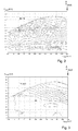
- Fig. 2 shows a diagram illustrating by way of example the behavior of the boost pressure p in the region of the inlet of the charge air cooler 12 as a function of the speed n mot and power output P mot of the internal combustion engine 20. Accordingly, the boost pressure p increases almost independently of the rotational speed n mot of the internal combustion engine 20 with its power output P mot . Therefore, if the boost pressure p is used as the control variable for specifying the cooling air quantity M that acts on the charge air cooler 12, the latter in turn depends essentially exclusively on the power output P mot of the internal combustion engine 20.
- Fig. 3 shows a diagram that exemplifies the required to maintain a certain temperature of the charge air cooling air quantity M - represented by an associated speed N of the fan rotor 28 - in dependence on the speed n mot and power output P mot of the engine 20 illustrated. Accordingly, the amount of cooling air M shows a slight decrease with the speed n mot of the engine 20. It is therefore advantageous if the amount of cooling air M to ensure a constant cooling of the charge air at the rated speed, ie at the permissible for continuous operation maximum speed n mot of Internal combustion engine 20 oriented, M ⁇ ⁇ ⁇ p P mot ⁇ n ⁇ mot .
- ⁇ is a coefficient that depends, inter alia, on the efficiency of the charge air cooler 12 or the fan device 22. In this way, a sufficient cooling of the charge air is always ensured.
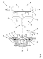
- Fig. 4 shows a second embodiment of the device according to the invention. This is different from the one in Fig. 1 illustrated first embodiment with respect to the manner of controlling the rotational speed of the fan rotor 28th
- the drive unit 26 is connected to the fan rotor 28 via a coupling 58 in connection, the coupling closure by means of the adjusting device 44 is variable.
- the clutch connection By changing the clutch connection, the rotational speed of the fan rotor 28 and thus the generated for acting on the charge air cooler 12 Cooling air quantity to be controlled independently of the drive unit 26.
- the internal combustion engine 20 is used as a drive unit 26, wherein this is connected via a belt drive or a flexible shaft with the coupling 58 in connection.
- the clutch 58 is a viscous fan clutch formed as part of the fan device 22.
- This comprises a drive-side rotor 62, which is arranged in a working chamber 60 and forms with the walls of the working space 60 a plurality of shear gaps 64 for producing a coupling closure with a driven-side housing 66.
- the working space 60 is divided off from a storage space 68 for hydraulic fluid by a partition wall 70, wherein the partition wall 70 has a plurality of circumferentially arranged pumping ports 72, by means of which in the case of a relative rotation of the rotor 62 relative to the housing 66 in the direction of the working space 60 überrendering hydraulic fluid flow can be generated , Furthermore, a plurality of control openings 74 are arranged in the partition 70, which allow a return flow of hydraulic fluid into the reservoir 68. By changing the amount of hydraulic fluid flowing back by means of a charge pressure controlled proportional valve 76 comprised by the adjusting device 44, the coupling closure can be selectively changed.
- Fig. 5 shows a schematically illustrated third embodiment of the device according to the invention. This is different from the one in Fig. 2 illustrated second embodiment with respect to the manner of controlling the amount of cooling air applied to the charge air cooler 12.
- the fan rotor 28 has a multiplicity of rotor blades 78 which can be adjusted with respect to their delivery cross-section, wherein the adjustment of the rotor blades 78 takes place by means of a charge-pressure-controlled actuating element 80 encompassed by the adjusting device 44.
- the actuating element 80 can be deflected in such a way as to counteract a restoring spring force in such a way that the rotor blades 78 are pivoted with increasing charge pressure in the sense of increasing the delivery cross section or the angle of attack.
- each of the adjustable rotor blades 78 may be assigned a separate actuating element 80, wherein the actuating elements 80 can be acted upon by means of the boost pressure via an annular channel 84 extending in the circumference of a fan hub 82.
- the engine 20 is used as a drive unit 26, wherein this is connected via a belt drive or a flexible shaft with the drive shaft 34 in connection.
Landscapes
- Engineering & Computer Science (AREA)
- Physics & Mathematics (AREA)
- Thermal Sciences (AREA)
- Chemical & Material Sciences (AREA)
- Combustion & Propulsion (AREA)
- Mechanical Engineering (AREA)
- General Engineering & Computer Science (AREA)
- Supercharger (AREA)
- Cooling, Air Intake And Gas Exhaust, And Fuel Tank Arrangements In Propulsion Units (AREA)
Abstract
Description
- Die Erfindung betrifft eine Vorrichtung zur Steuerung der Temperatur eines durch einen luftgekühlten Ladeluftkühler hindurchtretenden Ladeluftstroms für einen aufgeladenen Verbrennungsmotor, mit einer Lüftereinrichtung zur Erzeugung eines den Ladeluftkühler beaufschlagenden Kühlluftstroms, und mit einer Stelleinrichtung zur Beeinflussung der Kühlluftmenge nach Maßgabe einer zugeführten Steuergröße.
- Derartige Ladeluftkühler werden bei aufgeladenen Verbrennungsmotoren, insbesondere bei Dieselmotoren eingesetzt, um die mittels eines Abgasturboladers verdichtete und dabei erhitzte Ladeluft zur Erhöhung des Liefergrades und damit der Leistungsabgabe des Verbrennungsmotors abzukühlen.
- Die Offenlegungsschrift
DE 10 2207 005 393 A1 offenbart in diesem Zusammenhang eine Vorrichtung zur Regelung der Ladelufttemperatur bei einem luftgekühlten Ladeluftkühler für eine Brennkraftmaschine in einem Kraftfahrzeug. Der Ladeluftkühler weist einen Eintritts- und Austrittsbereich auf, wobei jedem der beiden Bereiche ein Temperatursensor zur Erfassung einer zugehörigen Ladelufttemperatur zugeordnet ist. Des Weiteren ist ein bezüglich seiner Drehzahl regelbarer Lüfter zur Erzeugung eines den Ladeluftkühler beaufschlagenden Kühlluftstroms vorhanden. Eine Regelungseinrichtung passt die Drehzahl des Lüfters nach Maßgabe der von den Temperatursensoren erfassten Ladelufttemperaturen derart an, dass eine Kühlung der Ladeluft entsprechend einer am Austrittsbereich einzuhaltenden Ladelufttemperatur erfolgt. Da dies die Verwendung einer komplexen Closed-Loop-Regelung voraussetzt, ist die bekannte Vorrichtung vergleichsweise aufwendig aufgebaut. - Es ist daher Aufgabe der vorliegenden Erfindung, eine bezüglich ihres Aufbaus vereinfachte Vorrichtung der eingangs genannten Art anzugeben.
- Diese Aufgabe wird durch eine Vorrichtung mit den Merkmalen des Patentanspruchs 1 gelöst.
- Die Vorrichtung zur Steuerung der Temperatur eines durch einen luftgekühlten Ladeluftkühler hindurchtretenden Ladeluftstroms für einen aufgeladenen Verbrennungsmotor umfasst neben einer Lüftereinrichtung zur Erzeugung eines den Ladeluftkühler beaufschlagenden Kühlluftstroms des Weiteren eine Stelleinrichtung zur Beeinflussung der Kühlluftmenge nach Maßgabe einer zugeführten Steuergröße. Erfindungsgemäß gibt die Steuergröße einen am Ladeluftkühler anliegenden Ladedruck wieder.
- Der erfindungsgemäßen Vorrichtung liegt die Erkenntnis zugrunde, dass der von einem Abgasturbolader erzeugte Ladedruck bei einem aufgeladenen Verbrennungsmotor nahezu unabhängig von der Drehzahl des Verbrennungsmotors mit dessen Leistungsabgabe zunimmt. Wird daher der Ladedruck als Steuergröße zur Vorgabe der den Ladeluftkühler beaufschlagenden Kühlluftmenge herangezogen, hängt letztere ihrerseits im Wesentlichen ausschließlich von der Leistungsabgabe des Verbrennungsmotors ab. Da die zur Einhaltung einer bestimmten Temperatur der Ladeluft erforderliche Kühlluftmenge in der Regel eine geringfügige Abnahme mit der Drehzahl des Verbrennungsmotors zeigt, ist es zur Sicherstellung einer gleichbleibenden Kühlung der Ladeluft von Vorteil, wenn sich die Kühlluftmenge an der Nenndrehzahl, d.h. an der für den Dauerbetrieb zulässigen Höchstdrehzahl des Verbrennungsmotors orientiert.
- Die erfindungsgemäße Vorrichtung ist aufgrund der nach Maßgabe des Ladedrucks vorgenommenen Open-Loop-Steuerung der Kühlluftmenge vergleichsweise einfach aufgebaut.
- Vorteilhafte Ausführungen der Vorrichtung gehen aus den Unteransprüchen hervor.
- Da sich Änderungen des Ladedrucks, wie sie aufgrund einer fahrtbedingt schwankenden Leistungsabgabe des Verbrennungsmotors verursacht werden, ausgehend vom Abgasturbolader zeitverzögert in Richtung des Ladeluftkühlers ausbreiten, kann zur Verringerung der thermischen Belastung des Ladeluftkühlers eine Vorsteuerung der Stelleinrichtung erfolgen. Hierzu wird der Ladedruck vorzugsweise im Bereich zwischen einem Auslass des Abgasturboladers und einem Einlass des Ladeluftkühlers abgegriffen.
- Die Lüftereinrichtung weist zur Erzeugung des Kühlluftstroms insbesondere einen mittels eines Antriebsaggregats in Drehung versetzbaren Lüfterrotor auf. Der Lüfterrotor umfasst eine Vielzahl radial ausgerichteter Förderflügel, die gleichmäßig am Umfang einer in einem Lüftergehäuse drehbar gelagerten Antriebsachse angebracht sind. An dem Lüftergehäuse ist ein mit der Außenatmosphäre kommunizierender Kühllufteinlass sowie ein dem Ladeluftkühler zugewandter Kühlluftauslass ausgebildet. Ein dem Ladeluftkühler vorgeschaltetes Filterelement verhindert ein Eindringen unerwünschter Schmutzpartikel, die mit dem Kühlluftstrom aus der Außenatmosphäre angesaugt werden und zu einer Beeinträchtigung der Kühlleistung des Ladeluftkühlers führen können. Das Lüftergehäuse kann gemeinsam mit dem Ladeluftkühler eine in einem Motorraum eines Kraftfahrzeugs untergebrachte Kühlerbaugruppe bilden, wobei der Ladeluftkühler über hitzbeständige Gummiluftleitungen mit dem Abgasturbolader bzw. dem Verbrennungsmotor des Kraftfahrzeugs in Verbindung steht.
- Bei dem Antriebsaggregat handelt es sich insbesondere um einen Hydromotor, der sich durch Zuführung eines unter Druck stehenden Hydraulikflüssigkeitsstroms antreiben lässt, wobei die zugeführte Hydraulikflüssigkeitsmenge mittels der Stelleinrichtung veränderbar ist. Der Hydromotor selbst kann von herkömmlicher Bauart sein und einen in einem Motorgehäuse unter Einfluss des Hydraulikflüssigkeitsstroms rotierenden Verdrängerkolben aufweisen, der mit einer aus dem Motorgehäuse herausgeführten Antriebsachse drehfest verbunden ist. Die Erzeugung des Hydraulikflüssigkeitsstroms erfolgt beispielsweise mittels einer aus einem Hydraulikflüssigkeitsspeicher gespeisten Hydraulikpumpe, die mittels des Verbrennungsmotors angetrieben wird. Durch Veränderung der dem Hydromotor zugeführten Hydraulikflüssigkeitsmenge oder eines von der Hydraulikpumpe bzw. dem Hydromotor umfassten verstellbaren Verdrängervolumens kann die Drehzahl des Lüfterrotors und damit die zur Beaufschlagung des Ladeluftkühlers erzeugte Kühlluftmenge gezielt gesteuert werden.
- Insbesondere besteht zur Veränderung der dem Hydromotor zugeführten Hydraulikflüssigkeitsmenge die Möglichkeit, dass die Stelleinrichtung ein ladedruckgesteuertes Proportionalventil aufweist.
- Vorzugsweise ist das Proportionalventil im Hydraulikflüssigkeitsstrom als Umgehungsventil parallel zum Hydromotor angeordnet. Das Umgehungsventil umfasst einen Ventilschieber, der nach Maßgabe des an einem Steuereingang des Umgehungsventils anliegenden Ladedrucks entgegen einer rückstellenden Federkraft derart in eine durchlässige Ventilstellung verbringbar ist, dass der Anteil der an dem Hydromotor vorbeigeleiteten Hydraulikflüssigkeitsmenge mit zunehmendem Ladedruck verringert wird.
- Des Weiteren ist es denkbar, dass das Antriebsaggregat mit dem Lüfterrotor über eine Kupplung in Verbindung steht, deren Kupplungsschluss mittels der Stelleinrichtung veränderbar ist. Durch Veränderung des Kupplungsschlusses kann die Drehzahl des Lüfterrotors und damit die zur Beaufschlagung des Ladeluftkühlers erzeugte Kühlluftmenge unabhängig vom Antriebsaggregat gesteuert werden. Die Verwendung der Kupplung bietet sich daher vor allem dann an, wenn als Antriebsaggregat der Verbrennungsmotor genutzt wird, wobei dieser beispielsweise über einen Riementrieb oder eine flexible Welle mit der Kupplung in Verbindung steht.
- Insbesondere handelt es sich bei der Kupplung um eine als Bestandteil der Lüftereinrichtung ausgebildete Visco-Lüfterkupplung. Diese umfasst einen in einem Arbeitsraum angeordneten antriebsseitigen Rotor, der mit den Wänden des Arbeitsraums mehrere Scherspalte zur Herstellung eines Kupplungsschlusses mit einem abtriebsseitigen Gehäuse bildet. Der Arbeitsraum ist gegenüber einem Vorratsraum für Hydraulikflüssigkeit durch eine Trennwand abgeteilt, wobei die Trennwand mehrere umfangsmäßig angeordnete Pumpöffnungen aufweist, mittels derer im Falle einer Relativdrehung des Rotors gegenüber dem Gehäuse ein in Richtung des Arbeitsraums übertretender Hydraulikflüssigkeitsstrom erzeugbar ist. Des Weiteren sind in der Trennwand mehrere Steueröffnungen angeordnet, die einen Rückstrom von Hydraulikflüssigkeit in den Vorratsraum erlauben. Durch Veränderung der zurückströmenden Hydraulikflüssigkeitsmenge mittels eines von der Stelleinrichtung umfassten ladedruckgesteuerten Proportionalventils kann der Kupplungsschluss gezielt verändert werden.
- Zur Veränderung der den Ladeluftkühler beaufschlagenden Kühlluftmenge ist es ferner denkbar, dass der Lüfterrotor eine Vielzahl von bezüglich ihres Förderquerschnitts verstellbaren Rotorflügeln aufweist, wobei die Verstellung der Rotorflügel mittels eines von der Stelleinrichtung umfassten ladedruckgesteuerten Betätigungselements erfolgt. Das Betätigungselement ist nach Maßgabe des Ladedrucks entgegen einer rückstellenden Federkraft derart auslenkbar, dass die Rotorflügel mit zunehmendem Ladedruck im Sinne einer Vergrößerung des Förderquerschnitts verschwenkt werden.
- Die erfindungsgemäße Vorrichtung wird im Folgenden anhand der beigefügten Zeichnungen näher erläutert. Dabei sind hinsichtlich ihrer Funktion übereinstimmende bzw. vergleichbare Bauteile mit denselben Bezugszeichen gekennzeichnet. Es zeigen:
- Fig. 1
- ein schematisch dargestelltes erstes Ausführungsbei- spiel der erfindungsgemäßen Vorrichtung,
- Fig. 2
- ein Diagramm, das beispielhaft das Verhalten des Lade- drucks in Abhängigkeit der Drehzahl und Leistungsabga- be des Verbrennungsmotors veranschaulicht,
- Fig. 3
- ein Diagramm, das beispielhaft die zur Einhaltung ei- ner bestimmten Temperatur der Ladeluft erforderliche Kühlluftmenge veranschaulicht,
- Fig. 4
- ein schematisch dargestelltes zweites Ausführungsbei- spiel der erfindungsgemäßen Vorrichtung, und
- Fig. 5
- ein schematisch dargestelltes drittes Ausführungsbei- spiel der erfindungsgemäßen Vorrichtung.
-
Fig. 1 zeigt ein erstes Ausführungsbeispiel der erfindungsgemäßen Vorrichtung zur Steuerung der Temperatur eines durch einen Ladeluftkühler hindurchtretenden Ladeluftstroms. - Die Vorrichtung 10 umfasst einen luftgekühlten Ladeluftkühler 12, der über hitzebeständige Gummiluftleitungen 14, 16 einlassseitig mit einem Abgasturbolader 18 und auslassseitig mit einem aufgeladenen Verbrennungsmotor 20 eines nicht dargestellten Kraftfahrzeugs in Verbindung steht. Der aufgeladene Verbrennungsmotor 20 ist beispielsweise als Dieselmotor ausgebildet.
- Bei dem Kraftfahrzeug handelt es sich insbesondere um ein landwirtschaftliches Nutzfahrzeug, beispielsweise um einen Traktor, eine Erntemaschine, einen Feldhäcksler oder eine selbstfahrende Spritzmaschine.
- Eine Lüftereinrichtung 22 dient der Erzeugung eines den Ladeluftkühler 12 beaufschlagenden Kühlluftstroms 24. Die Lüftereinrichtung 22 weist zur Erzeugung des Kühlluftstroms 24 einen mittels eines Antriebsaggregats 26 in Drehung versetzbaren Lüfterrotor 28 auf. Der Lüfterrotor 28 umfasst eine Vielzahl radial ausgerichteter Förderflügel 30, die gleichmäßig am Umfang einer in einem Lüftergehäuse 32 drehbar gelagerten Antriebsachse 34 angebracht sind. An dem Lüftergehäuse 32 ist ein mit der Außenatmosphäre kommunizierender Kühllufteinlass 36 sowie ein dem Ladeluftkühler 12 zugewandter Kühlluftauslass 38 ausgebildet. Ein dem Ladeluftkühler 12 vorgeschaltetes Filterelement 40 verhindert ein Eindringen unerwünschter Schmutzpartikel, die mit dem Kühlluftstrom 24 angesaugt werden und zu einer Beeinträchtigung der Kühlleistung des Ladeluftkühlers 12 führen können. Das Lüftergehäuse 32 bildet gemeinsam mit dem Ladeluftkühler 12 eine in einem Motorraum des Kraftfahrzeugs untergebrachte Kühlerbaugruppe.
- Beispielsgemäß handelt es sich bei dem Antriebsaggregat 26 um einen Hydromotor 42, der sich durch Zuführung eines unter Druck stehenden Hydraulikflüssigkeitsstroms antreiben lässt. Die zugeführte Hydraulikflüssigkeitsmenge ist mittels einer Stelleinrichtung 44 nach Maßgabe eines am Ladeluftkühler 12 vorliegenden Ladedrucks veränderbar. Die Erzeugung des Hydraulikflüssigkeitsstroms erfolgt mittels einer aus einem Hydraulikflüssigkeitsspeicher 46 gespeisten Hydraulikflüssigkeitspumpe 48, die mittels des Verbrennungsmotors 20 angetrieben wird.
- Der Hydromotor 42 selbst ist von herkömmlicher Bauart und weist einen in einem Motorgehäuse unter Einfluss des Hydraulikflüssigkeitsstroms rotierenden Verdrängerkolben auf, der mit einer aus dem Motorgehäuse herausgeführten Antriebsachse 50 drehfest verbunden ist. Durch Veränderung der dem Hydromotor 42 zugeführten Hydraulikflüssigkeitsmenge kann die Drehzahl des Lüfterrotors 28 und damit die zur Beaufschlagung des Ladeluftkühlers 12 erzeugte Kühlluftmenge gezielt gesteuert werden.
- Zur Steuerung der dem Hydromotor 42 zugeführten Hydraulikflüssigkeitsmenge weist die Stelleinrichtung 44 ein ladedruckgesteuertes Proportionalventil 52 auf. Das Proportionalventil 52 ist in Gestalt eines Umgehungsventils parallel zum Hydromotor 42 angeordnet. Das Umgehungsventil umfasst einen Ventilschieber, der nach Maßgabe des an einem Steuereingang 54 des Umgehungsventils anliegenden Ladedrucks entgegen einer rückstellenden Federkraft derart in eine durchlässige Ventilstellung verbringbar ist, dass der Anteil der an dem Hydromotor 42 vorbeigeleiteten Hydraulikflüssigkeitsmenge mit zunehmendem Ladedruck verringert wird. Hierzu wird der Ladedruck im Bereich des Einlasses des Ladeluftkühlers 12 abgegriffen und dem Umgehungsventil als Steuergröße über eine Druckleitung 56 zugeführt.
-
Fig. 2 zeigt ein Diagramm, das beispielhaft das Verhalten des Ladedrucks p im Bereich des Einlasses des Ladeluftkühlers 12 in Abhängigkeit der Drehzahl nmot und Leistungsabgabe Pmot des Verbrennungsmotors 20 veranschaulicht. Demgemäß nimmt der Ladedruck p nahezu unabhängig von der Drehzahl nmot des Verbrennungsmotors 20 mit dessen Leistungsabgabe Pmot zu. Wird daher der Ladedruck p als Steuergröße zur Vorgabe der den Ladeluftkühler 12 beaufschlagenden Kühlluftmenge M herangezogen, hängt letztere ihrerseits im Wesentlichen ausschließlich von der Leistungsabgabe Pmot des Verbrennungsmotors 20 ab. -
Fig. 3 zeigt ein Diagramm, das beispielhaft die zur Einhaltung einer bestimmten Temperatur der Ladeluft erforderliche Kühlluftmenge M - wiedergegeben durch eine zugehörige Drehzahl N des Lüfterrotors 28 - in Abhängigkeit der Drehzahl nmot und Leistungsabgabe Pmot des Verbrennungsmotors 20 veranschaulicht. Demgemäß zeigt die Kühlluftmenge M eine geringfügige Abnahme mit der Drehzahl nmot des Verbrennungsmotors 20. Es ist daher von Vorteil, wenn sich die Kühlluftmenge M zur Sicherstellung einer gleichbleibenden Kühlung der Ladeluft an der Nenndrehzahl, d.h. an der für den Dauerbetrieb zulässigen Höchstdrehzahl nmot des Verbrennungsmotors 20 orientiert,
wobei κ ein unter anderem vom Wirkungsgrad des Ladeluftkühlers 12 bzw. der Lüftereinrichtung 22 abhängiger Koeffizient ist. Auf diese Weise ist stets eine ausreichende Kühlung der Ladeluft sichergestellt. -
Fig. 4 zeigt ein zweites Ausführungsbeispiel der erfindungsgemäßen Vorrichtung. Dieses unterscheidet sich von dem inFig. 1 dargestellten ersten Ausführungsbeispiel bezüglich der Art und Weise der Steuerung der Drehzahl des Lüfterrotors 28. - Demgemäß steht das Antriebsaggregat 26 mit dem Lüfterrotor 28 über eine Kupplung 58 in Verbindung, deren Kupplungsschluss mittels der Stelleinrichtung 44 veränderbar ist. Durch Veränderung des Kupplungsschlusses kann die Drehzahl des Lüfterrotors 28 und damit die zur Beaufschlagung des Ladeluftkühlers 12 erzeugte Kühlluftmenge unabhängig vom Antriebsaggregat 26 gesteuert werden.
- Im vorliegenden Fall wird als Antriebsaggregat 26 der Verbrennungsmotor 20 genutzt, wobei dieser über einen Riementrieb oder eine flexible Welle mit der Kupplung 58 in Verbindung steht.
- Beispielsgemäß handelt es sich bei der Kupplung 58 um eine als Bestandteil der Lüftereinrichtung 22 ausgebildete Visco-Lüfterkupplung. Diese umfasst einen in einem Arbeitsraum 60 angeordneten antriebsseitigen Rotor 62, der mit den Wänden des Arbeitsraums 60 mehrere Scherspalte 64 zur Herstellung eines Kupplungsschlusses mit einem abtriebsseitigen Gehäuse 66 bildet. Der Arbeitsraum 60 ist gegenüber einem Vorratsraum 68 für Hydraulikflüssigkeit durch eine Trennwand 70 abgeteilt, wobei die Trennwand 70 mehrere umfangsmäßig angeordnete Pumpöffnungen 72 aufweist, mittels derer im Falle einer Relativdrehung des Rotors 62 gegenüber dem Gehäuse 66 ein in Richtung des Arbeitsraums 60 übertretender Hydraulikflüssigkeitsstrom erzeugbar ist. Des weiteren sind in der Trennwand 70 mehrere Steueröffnungen 74 angeordnet, die einen Rückstrom von Hydraulikflüssigkeit in den Vorratsraum 68 erlauben. Durch Veränderung der zurückströmenden Hydraulikflüssigkeitsmenge mittels eines von der Stelleinrichtung 44 umfassten ladedruckgesteuerten Proportionalventils 76 kann der Kupplungsschluss gezielt verändert werden.
-
Fig. 5 zeigt ein schematisch dargestelltes drittes Ausführungsbeispiel der erfindungsgemäßen Vorrichtung. Dieses unterscheidet sich von dem inFig. 2 dargestellten zweiten Ausführungsbeispiel bezüglich der Art und Weise der Steuerung der den Ladeluftkühler 12 beaufschlagenden Kühlluftmenge. - Demgemäß weist der Lüfterrotor 28 eine Vielzahl von bezüglich ihres Förderquerschnitts verstellbaren Rotorflügeln 78 auf, wobei die Verstellung der Rotorflügel 78 mittels eines von der Stelleinrichtung 44 umfassten ladedruckgesteuerten Betätigungselements 80 erfolgt. Das Betätigungselement 80 ist nach Maßgabe des Ladedrucks entgegen einer rückstellenden Federkraft derart auslenkbar, dass die Rotorflügel 78 mit zunehmendem Ladedruck im Sinne einer Vergrößerung des Förderquerschnitts bzw. des Anstellwinkels verschwenkt werden. Hierbei kann jedem der verstellbaren Rotorflügel 78 ein separates Betätigungselement 80 zugeordnet sein, wobei die Betätigungselemente 80 über einen im Umfang einer Lüfternabe 82 verlaufenden Ringkanal 84 mittels des Ladedrucks beaufschlagbar sind.
- Auch hier wird als Antriebsaggregat 26 der Verbrennungsmotor 20 genutzt, wobei dieser über einen Riementrieb oder eine flexible Welle mit der Antriebsachse 34 in Verbindung steht.
Claims (10)
- Vorrichtung zur Steuerung der Temperatur eines durch einen luftgekühlten Ladeluftkühler (12) hindurchtretenden Ladeluftstroms für einen aufgeladenen Verbrennungsmotor (20), mit einer Lüftereinrichtung (22) zur Erzeugung eines den Ladeluftkühler (12) beaufschlagenden Kühlluftstroms (24), und mit einer Stelleinrichtung (44) zur Beeinflussung der Kühlluftmenge nach Maßgabe einer zugeführten Steuergröße, dadurch gekennzeichnet, dass die Steuergröße einen am Ladeluftkühler (12) vorliegenden Ladedruck wiedergibt.
- Vorrichtung nach Anspruch 1, dadurch gekennzeichnet, dass der Ladedruck im Bereich zwischen einem Auslass eines Abgasturboladers (18) und einem Einlass des Ladeluftkühlers (12) abgegriffen wird.
- Vorrichtung nach Anspruch 1 oder 2, dadurch gekennzeichnet, dass die Lüftereinrichtung (22) zur Erzeugung des Kühlluftstroms (24) einen mittels eines Antriebsaggregats (26) in Drehung versetzbaren Lüfterrotor (28) aufweist.
- Vorrichtung nach einem der Ansprüche 1 bis 3, dadurch gekennzeichnet, dass es sich bei dem Antriebsaggregat (26) um einen Hydromotor (42) handelt, der sich durch Zuführung eines unter Druck stehenden Hydraulikflüssigkeitsstroms antreiben lässt, wobei die zugeführte Hydraulikflüssigkeitsmenge mittels der Stelleinrichtung (44) veränderbar ist.
- Vorrichtung nach einem der Ansprüche 1 bis 4, dadurch gekennzeichnet, dass die Stelleinrichtung (44) ein ladedruckgesteuertes Proportionalventil (52) aufweist.
- Vorrichtung nach einem der Ansprüche 1 bis 5, dadurch gekennzeichnet, dass das Proportionalventil (52) im Hydraulikflüssigkeitsstrom als Umgehungsventil parallel zum Hydromotor (42) angeordnet ist.
- Vorrichtung nach einem der Ansprüche 1 bis 6, dadurch gekennzeichnet, dass das Antriebsaggregat (26) mit dem Lüfterrotor (28) über eine Kupplung (58) in Verbindung steht, deren Kupplungsschluss mittels der Stelleinrichtung (44) veränderbar ist.
- Vorrichtung nach einem der Ansprüche 1 bis 7, dadurch gekennzeichnet, dass es sich bei der Kupplung (58) um eine als Bestandteil der Lüftereinrichtung (22) ausgebildete Visco-Lüfterkupplung handelt.
- Vorrichtung nach einem der Ansprüche 1 bis 8, dadurch gekennzeichnet, dass der Lüfterrotor (28) eine Vielzahl von bezüglich ihres Förderquerschnitts verstellbaren Rotorflügeln (78) aufweist, wobei die Verstellung der Rotorflügel (78) mittels eines von der Stelleinrichtung (44) umfassten ladedruckgesteuerten Betätigungselements (80) erfolgt.
- Kraftfahrzeug, insbesondere landwirtschaftliches Nutzfahrzeug, mit einer Vorrichtung (10) zur Steuerung der Temperatur eines durch einen Ladeluftkühler (12) hindurchtretenden Ladeluftstroms für einen Verbrennungsmotor (20) nach einem der Ansprüche 1 bis 9.
Applications Claiming Priority (1)
| Application Number | Priority Date | Filing Date | Title |
|---|---|---|---|
| DE102009026613A DE102009026613A1 (de) | 2009-05-29 | 2009-05-29 | Vorrichtung zur Steuerung der Temperatur eines durch einen Ladeluftkühler hindurchtretenden Ladeluftstroms |
Publications (2)
| Publication Number | Publication Date |
|---|---|
| EP2264294A1 true EP2264294A1 (de) | 2010-12-22 |
| EP2264294B1 EP2264294B1 (de) | 2012-02-01 |
Family
ID=42357653
Family Applications (1)
| Application Number | Title | Priority Date | Filing Date |
|---|---|---|---|
| EP10162559A Active EP2264294B1 (de) | 2009-05-29 | 2010-05-11 | Vorrichtung zur Steuerung der Temperatur eines durch einen Ladeluftkühler hindurchtretenden Ladeluftstroms |
Country Status (5)
| Country | Link |
|---|---|
| US (1) | US8429911B2 (de) |
| EP (1) | EP2264294B1 (de) |
| AT (1) | ATE543991T1 (de) |
| DE (1) | DE102009026613A1 (de) |
| ES (1) | ES2381582T3 (de) |
Cited By (3)
| Publication number | Priority date | Publication date | Assignee | Title |
|---|---|---|---|---|
| EP2530273A1 (de) * | 2011-06-01 | 2012-12-05 | Joseph Vögele AG | Baumaschine mit automatischer Lüfterdrehzahlregelung |
| CN103790692A (zh) * | 2012-10-30 | 2014-05-14 | 福特环球技术公司 | 通过控制增压空气冷却器温度的增压空气冷却器中的凝结控制 |
| US9670930B2 (en) | 2011-10-07 | 2017-06-06 | Joseph Vogele Ag | Construction machine with automatic fan rotational speed regulation |
Families Citing this family (8)
| Publication number | Priority date | Publication date | Assignee | Title |
|---|---|---|---|---|
| DE102011089035B4 (de) * | 2011-12-19 | 2017-05-24 | Bayerische Motoren Werke Aktiengesellschaft | Steuerung verstellbarer Kühlluftklappen eines Kraftfahrzeugs mit einem einen Lader umfassenden Verbrennungsmotor |
| DE112013000855B4 (de) * | 2012-02-06 | 2024-08-08 | Hitachi Construction Machinery Co., Ltd. | Transportfahrzeug |
| US9394858B2 (en) * | 2013-03-11 | 2016-07-19 | Ford Global Technologies, Llc | Charge air cooling control for boosted engines to actively maintain targeted intake manifold air temperature |
| US9534546B2 (en) | 2014-05-14 | 2017-01-03 | Caterpillar Inc. | System and method for operating engine |
| US9551275B2 (en) | 2014-08-07 | 2017-01-24 | Caterpillar Inc. | Cooling system having pulsed fan control |
| CN108519236A (zh) * | 2018-04-08 | 2018-09-11 | 上海柴油机股份有限公司 | 喷淋式整车中冷器台架试验恒温控制装置 |
| CN112483237B (zh) * | 2020-12-08 | 2022-01-11 | 湖南行必达网联科技有限公司 | 一种电控硅油风扇控制方法、装置、系统和车辆 |
| CN113914990B (zh) * | 2021-09-28 | 2022-10-11 | 三一重机有限公司 | 发动机热管理控制方法、系统及作业机械 |
Citations (7)
| Publication number | Priority date | Publication date | Assignee | Title |
|---|---|---|---|---|
| EP0097230A2 (de) * | 1982-06-18 | 1984-01-04 | Süddeutsche Kühlerfabrik Julius Fr. Behr GmbH & Co. KG | Lüfterantrieb für eine Kühlanlage, insbesondere für Schienenfahrzeuge |
| JPS60206934A (ja) * | 1984-03-30 | 1985-10-18 | Hino Motors Ltd | 過給機付き内燃機関の給気冷却装置 |
| EP0496085A1 (de) * | 1991-01-22 | 1992-07-29 | MAN Nutzfahrzeuge Aktiengesellschaft | Brennkraftmaschine mit zweistufiger Ladeluftkühlung |
| WO1998025012A1 (en) * | 1996-12-02 | 1998-06-11 | Caterpillar Inc. | Air to air aftercooler heated bypass with load sensing switching valve |
| GB2374124A (en) * | 2000-12-20 | 2002-10-09 | Borgwarner Inc | Cooling fan control system for a pitch adjustable variable flow rate fan |
| FR2895452A1 (fr) * | 2005-12-28 | 2007-06-29 | Renault Sas | Moteur suralimente adapte a ameliorer le refroidissement de l'air admis dans le moteur et vehicule automobile comprenant un tel moteur |
| DE102007005393A1 (de) | 2007-02-03 | 2008-08-07 | Behr Industry Gmbh & Co. Kg | Vorrichtung und Verfahren zur Regelung der Ladelufttemperatur |
Family Cites Families (4)
| Publication number | Priority date | Publication date | Assignee | Title |
|---|---|---|---|---|
| DE3200682A1 (de) * | 1982-01-13 | 1983-07-21 | Klöckner-Humboldt-Deutz AG, 5000 Köln | Fluessigkeitsgekuehlte brennkraftmaschine mit aufladung |
| DE3200686A1 (de) * | 1982-01-13 | 1983-07-21 | Klöckner-Humboldt-Deutz AG, 5000 Köln | Luftgekuehlte brennkraftmaschine mit aufladung und ladeluftkuehlung |
| DE3200688A1 (de) * | 1982-01-13 | 1983-07-21 | Klöckner-Humboldt-Deutz AG, 5000 Köln | Vorrichtung zur regelung der ladelufttemperatur einer aufgeladenen brennkraftmaschine |
| DE4104093A1 (de) * | 1991-02-11 | 1992-08-13 | Behr Gmbh & Co | Kuehlanlage fuer ein fahrzeug mit verbrennungsmotor |
-
2009
- 2009-05-29 DE DE102009026613A patent/DE102009026613A1/de not_active Withdrawn
-
2010
- 2010-05-11 AT AT10162559T patent/ATE543991T1/de active
- 2010-05-11 EP EP10162559A patent/EP2264294B1/de active Active
- 2010-05-11 ES ES10162559T patent/ES2381582T3/es active Active
- 2010-05-20 US US12/783,710 patent/US8429911B2/en not_active Expired - Fee Related
Patent Citations (7)
| Publication number | Priority date | Publication date | Assignee | Title |
|---|---|---|---|---|
| EP0097230A2 (de) * | 1982-06-18 | 1984-01-04 | Süddeutsche Kühlerfabrik Julius Fr. Behr GmbH & Co. KG | Lüfterantrieb für eine Kühlanlage, insbesondere für Schienenfahrzeuge |
| JPS60206934A (ja) * | 1984-03-30 | 1985-10-18 | Hino Motors Ltd | 過給機付き内燃機関の給気冷却装置 |
| EP0496085A1 (de) * | 1991-01-22 | 1992-07-29 | MAN Nutzfahrzeuge Aktiengesellschaft | Brennkraftmaschine mit zweistufiger Ladeluftkühlung |
| WO1998025012A1 (en) * | 1996-12-02 | 1998-06-11 | Caterpillar Inc. | Air to air aftercooler heated bypass with load sensing switching valve |
| GB2374124A (en) * | 2000-12-20 | 2002-10-09 | Borgwarner Inc | Cooling fan control system for a pitch adjustable variable flow rate fan |
| FR2895452A1 (fr) * | 2005-12-28 | 2007-06-29 | Renault Sas | Moteur suralimente adapte a ameliorer le refroidissement de l'air admis dans le moteur et vehicule automobile comprenant un tel moteur |
| DE102007005393A1 (de) | 2007-02-03 | 2008-08-07 | Behr Industry Gmbh & Co. Kg | Vorrichtung und Verfahren zur Regelung der Ladelufttemperatur |
Cited By (4)
| Publication number | Priority date | Publication date | Assignee | Title |
|---|---|---|---|---|
| EP2530273A1 (de) * | 2011-06-01 | 2012-12-05 | Joseph Vögele AG | Baumaschine mit automatischer Lüfterdrehzahlregelung |
| US9670930B2 (en) | 2011-10-07 | 2017-06-06 | Joseph Vogele Ag | Construction machine with automatic fan rotational speed regulation |
| CN103790692A (zh) * | 2012-10-30 | 2014-05-14 | 福特环球技术公司 | 通过控制增压空气冷却器温度的增压空气冷却器中的凝结控制 |
| CN103790692B (zh) * | 2012-10-30 | 2018-06-26 | 福特环球技术公司 | 通过控制增压空气冷却器温度的增压空气冷却器中的凝结控制 |
Also Published As
| Publication number | Publication date |
|---|---|
| ATE543991T1 (de) | 2012-02-15 |
| US20110120426A1 (en) | 2011-05-26 |
| US8429911B2 (en) | 2013-04-30 |
| DE102009026613A1 (de) | 2010-12-02 |
| ES2381582T3 (es) | 2012-05-29 |
| EP2264294B1 (de) | 2012-02-01 |
Similar Documents
| Publication | Publication Date | Title |
|---|---|---|
| EP2264294B1 (de) | Vorrichtung zur Steuerung der Temperatur eines durch einen Ladeluftkühler hindurchtretenden Ladeluftstroms | |
| DE60114987T2 (de) | Regelung eines abgasturboladers mit variabler turbinengeometrie durch messung des abgasdrucks | |
| DE60211384T2 (de) | Turbosystem für brennkraftmaschine und entsprechendes verfahren | |
| DE3636642C2 (de) | ||
| DE602005005540T2 (de) | Stufenlos einstellbares Getriebe für Lader | |
| DE102004059369A1 (de) | Motorturboladersteuermanagementsystem | |
| DE102010060943A1 (de) | System zum Kompensieren eines Turbolochs | |
| DE10355563A1 (de) | Brennkraftmaschine mit einem mechanischen Lader und einem Turbo-Compound | |
| DE102014219252A1 (de) | Brennkraftmaschine | |
| DE112013003307T5 (de) | Fahrzeughydrauliksteuervorrichtung | |
| DE3032218A1 (de) | Kolbenbrennkraftmaschine mit einem abgasturbolader | |
| WO2006089653A1 (de) | Motorbremsverfahren für eine brennkraftmaschine mit zwei in reihe geschalteten abgasturboladern | |
| DE102009055236A1 (de) | Verfahren und Vorrichtung zur Regelung eines Abgasturboladers | |
| DE102007019060A1 (de) | Brennkraftmaschine mit kombinierter Aufladung durch Abgasturbolader und mechanischer Lader | |
| DE102006024420A1 (de) | Regelungseinheit, Turboladersystem, Kraftfahrzeug mit einem Turboladersystem und Verfahren zum Regeln eines Turboladersystems | |
| DE102013001662A1 (de) | Verbrennungskraftmaschine für einen Kraftwagen | |
| DE19833147C2 (de) | Verfahren zur Einstellung der Motorbremsleistung einer aufgeladenen Brennkraftmaschine | |
| EP1504177B1 (de) | Variabler, zusätzlich angetriebener abgasturbolader einer brennkraftmaschine | |
| DE10327686A1 (de) | Brennkraftmaschine | |
| DE102004051889A1 (de) | Verfahren zum Betrieb einer aufgeladenen Brennkraftmaschine | |
| DE102009033519A1 (de) | Antriebsstrang mit einer Verbrennungskraftmaschine | |
| EP3009629B1 (de) | Verfahren und Vorrichtung zur Einstellung eines Ladedruckes in einer Brennkraftmaschine mit einem Druckwellenlader | |
| DE102008022627A1 (de) | Abgasturbolader für eine Brennkraftmaschine und Verfahren zum Betreiben eines Abgasturboladers einer Brennkraftmaschine | |
| EP3591186B1 (de) | Verfahren zum betreiben einer brennkraftmaschine mit einem dem verdichter zugeordneten trimmsteller | |
| EP2602449B1 (de) | Verbrennungskraftmaschine mit Abgasturbolader und Abgaskühler sowie Verfahren zur Steuerung/Regelung der Betriebstemperatur des Abgasturboladers |
Legal Events
| Date | Code | Title | Description |
|---|---|---|---|
| PUAI | Public reference made under article 153(3) epc to a published international application that has entered the european phase |
Free format text: ORIGINAL CODE: 0009012 |
|
| AK | Designated contracting states |
Kind code of ref document: A1 Designated state(s): AL AT BE BG CH CY CZ DE DK EE ES FI FR GB GR HR HU IE IS IT LI LT LU LV MC MK MT NL NO PL PT RO SE SI SK SM TR |
|
| AX | Request for extension of the european patent |
Extension state: BA ME RS |
|
| RIN1 | Information on inventor provided before grant (corrected) |
Inventor name: BACK, PETER Inventor name: STARK, WALDEMAR |
|
| 17P | Request for examination filed |
Effective date: 20110622 |
|
| GRAP | Despatch of communication of intention to grant a patent |
Free format text: ORIGINAL CODE: EPIDOSNIGR1 |
|
| RIC1 | Information provided on ipc code assigned before grant |
Ipc: F02B 29/04 20060101AFI20110729BHEP Ipc: F01P 7/02 20060101ALI20110729BHEP |
|
| GRAS | Grant fee paid |
Free format text: ORIGINAL CODE: EPIDOSNIGR3 |
|
| GRAA | (expected) grant |
Free format text: ORIGINAL CODE: 0009210 |
|
| AK | Designated contracting states |
Kind code of ref document: B1 Designated state(s): AL AT BE BG CH CY CZ DE DK EE ES FI FR GB GR HR HU IE IS IT LI LT LU LV MC MK MT NL NO PL PT RO SE SI SK SM TR |
|
| REG | Reference to a national code |
Ref country code: GB Ref legal event code: FG4D Free format text: NOT ENGLISH |
|
| REG | Reference to a national code |
Ref country code: AT Ref legal event code: REF Ref document number: 543991 Country of ref document: AT Kind code of ref document: T Effective date: 20120215 Ref country code: CH Ref legal event code: EP |
|
| REG | Reference to a national code |
Ref country code: DE Ref legal event code: R096 Ref document number: 502010000397 Country of ref document: DE Effective date: 20120329 |
|
| REG | Reference to a national code |
Ref country code: ES Ref legal event code: FG2A Ref document number: 2381582 Country of ref document: ES Kind code of ref document: T3 Effective date: 20120529 |
|
| REG | Reference to a national code |
Ref country code: NL Ref legal event code: VDEP Effective date: 20120201 |
|
| LTIE | Lt: invalidation of european patent or patent extension |
Effective date: 20120201 |
|
| PG25 | Lapsed in a contracting state [announced via postgrant information from national office to epo] |
Ref country code: LT Free format text: LAPSE BECAUSE OF FAILURE TO SUBMIT A TRANSLATION OF THE DESCRIPTION OR TO PAY THE FEE WITHIN THE PRESCRIBED TIME-LIMIT Effective date: 20120201 Ref country code: NL Free format text: LAPSE BECAUSE OF FAILURE TO SUBMIT A TRANSLATION OF THE DESCRIPTION OR TO PAY THE FEE WITHIN THE PRESCRIBED TIME-LIMIT Effective date: 20120201 Ref country code: HR Free format text: LAPSE BECAUSE OF FAILURE TO SUBMIT A TRANSLATION OF THE DESCRIPTION OR TO PAY THE FEE WITHIN THE PRESCRIBED TIME-LIMIT Effective date: 20120201 Ref country code: IS Free format text: LAPSE BECAUSE OF FAILURE TO SUBMIT A TRANSLATION OF THE DESCRIPTION OR TO PAY THE FEE WITHIN THE PRESCRIBED TIME-LIMIT Effective date: 20120601 Ref country code: NO Free format text: LAPSE BECAUSE OF FAILURE TO SUBMIT A TRANSLATION OF THE DESCRIPTION OR TO PAY THE FEE WITHIN THE PRESCRIBED TIME-LIMIT Effective date: 20120501 |
|
| REG | Reference to a national code |
Ref country code: IE Ref legal event code: FD4D |
|
| PG25 | Lapsed in a contracting state [announced via postgrant information from national office to epo] |
Ref country code: GR Free format text: LAPSE BECAUSE OF FAILURE TO SUBMIT A TRANSLATION OF THE DESCRIPTION OR TO PAY THE FEE WITHIN THE PRESCRIBED TIME-LIMIT Effective date: 20120502 Ref country code: LV Free format text: LAPSE BECAUSE OF FAILURE TO SUBMIT A TRANSLATION OF THE DESCRIPTION OR TO PAY THE FEE WITHIN THE PRESCRIBED TIME-LIMIT Effective date: 20120201 Ref country code: PL Free format text: LAPSE BECAUSE OF FAILURE TO SUBMIT A TRANSLATION OF THE DESCRIPTION OR TO PAY THE FEE WITHIN THE PRESCRIBED TIME-LIMIT Effective date: 20120201 Ref country code: PT Free format text: LAPSE BECAUSE OF FAILURE TO SUBMIT A TRANSLATION OF THE DESCRIPTION OR TO PAY THE FEE WITHIN THE PRESCRIBED TIME-LIMIT Effective date: 20120601 |
|
| PG25 | Lapsed in a contracting state [announced via postgrant information from national office to epo] |
Ref country code: CY Free format text: LAPSE BECAUSE OF FAILURE TO SUBMIT A TRANSLATION OF THE DESCRIPTION OR TO PAY THE FEE WITHIN THE PRESCRIBED TIME-LIMIT Effective date: 20120201 |
|
| PG25 | Lapsed in a contracting state [announced via postgrant information from national office to epo] |
Ref country code: CZ Free format text: LAPSE BECAUSE OF FAILURE TO SUBMIT A TRANSLATION OF THE DESCRIPTION OR TO PAY THE FEE WITHIN THE PRESCRIBED TIME-LIMIT Effective date: 20120201 Ref country code: SI Free format text: LAPSE BECAUSE OF FAILURE TO SUBMIT A TRANSLATION OF THE DESCRIPTION OR TO PAY THE FEE WITHIN THE PRESCRIBED TIME-LIMIT Effective date: 20120201 Ref country code: DK Free format text: LAPSE BECAUSE OF FAILURE TO SUBMIT A TRANSLATION OF THE DESCRIPTION OR TO PAY THE FEE WITHIN THE PRESCRIBED TIME-LIMIT Effective date: 20120201 Ref country code: IE Free format text: LAPSE BECAUSE OF FAILURE TO SUBMIT A TRANSLATION OF THE DESCRIPTION OR TO PAY THE FEE WITHIN THE PRESCRIBED TIME-LIMIT Effective date: 20120201 Ref country code: EE Free format text: LAPSE BECAUSE OF FAILURE TO SUBMIT A TRANSLATION OF THE DESCRIPTION OR TO PAY THE FEE WITHIN THE PRESCRIBED TIME-LIMIT Effective date: 20120201 Ref country code: RO Free format text: LAPSE BECAUSE OF FAILURE TO SUBMIT A TRANSLATION OF THE DESCRIPTION OR TO PAY THE FEE WITHIN THE PRESCRIBED TIME-LIMIT Effective date: 20120201 Ref country code: SE Free format text: LAPSE BECAUSE OF FAILURE TO SUBMIT A TRANSLATION OF THE DESCRIPTION OR TO PAY THE FEE WITHIN THE PRESCRIBED TIME-LIMIT Effective date: 20120201 |
|
| BERE | Be: lapsed |
Owner name: DEERE & CY Effective date: 20120531 |
|
| PG25 | Lapsed in a contracting state [announced via postgrant information from national office to epo] |
Ref country code: SK Free format text: LAPSE BECAUSE OF FAILURE TO SUBMIT A TRANSLATION OF THE DESCRIPTION OR TO PAY THE FEE WITHIN THE PRESCRIBED TIME-LIMIT Effective date: 20120201 |
|
| PLBE | No opposition filed within time limit |
Free format text: ORIGINAL CODE: 0009261 |
|
| STAA | Information on the status of an ep patent application or granted ep patent |
Free format text: STATUS: NO OPPOSITION FILED WITHIN TIME LIMIT |
|
| PG25 | Lapsed in a contracting state [announced via postgrant information from national office to epo] |
Ref country code: MC Free format text: LAPSE BECAUSE OF NON-PAYMENT OF DUE FEES Effective date: 20120531 |
|
| 26N | No opposition filed |
Effective date: 20121105 |
|
| PG25 | Lapsed in a contracting state [announced via postgrant information from national office to epo] |
Ref country code: MK Free format text: LAPSE BECAUSE OF FAILURE TO SUBMIT A TRANSLATION OF THE DESCRIPTION OR TO PAY THE FEE WITHIN THE PRESCRIBED TIME-LIMIT Effective date: 20120201 Ref country code: BE Free format text: LAPSE BECAUSE OF NON-PAYMENT OF DUE FEES Effective date: 20120531 |
|
| REG | Reference to a national code |
Ref country code: DE Ref legal event code: R097 Ref document number: 502010000397 Country of ref document: DE Effective date: 20121105 |
|
| PG25 | Lapsed in a contracting state [announced via postgrant information from national office to epo] |
Ref country code: MT Free format text: LAPSE BECAUSE OF FAILURE TO SUBMIT A TRANSLATION OF THE DESCRIPTION OR TO PAY THE FEE WITHIN THE PRESCRIBED TIME-LIMIT Effective date: 20120201 Ref country code: BG Free format text: LAPSE BECAUSE OF FAILURE TO SUBMIT A TRANSLATION OF THE DESCRIPTION OR TO PAY THE FEE WITHIN THE PRESCRIBED TIME-LIMIT Effective date: 20120501 |
|
| PG25 | Lapsed in a contracting state [announced via postgrant information from national office to epo] |
Ref country code: AL Free format text: LAPSE BECAUSE OF FAILURE TO SUBMIT A TRANSLATION OF THE DESCRIPTION OR TO PAY THE FEE WITHIN THE PRESCRIBED TIME-LIMIT Effective date: 20120201 |
|
| PG25 | Lapsed in a contracting state [announced via postgrant information from national office to epo] |
Ref country code: TR Free format text: LAPSE BECAUSE OF FAILURE TO SUBMIT A TRANSLATION OF THE DESCRIPTION OR TO PAY THE FEE WITHIN THE PRESCRIBED TIME-LIMIT Effective date: 20120201 |
|
| PG25 | Lapsed in a contracting state [announced via postgrant information from national office to epo] |
Ref country code: LU Free format text: LAPSE BECAUSE OF NON-PAYMENT OF DUE FEES Effective date: 20120511 Ref country code: SM Free format text: LAPSE BECAUSE OF FAILURE TO SUBMIT A TRANSLATION OF THE DESCRIPTION OR TO PAY THE FEE WITHIN THE PRESCRIBED TIME-LIMIT Effective date: 20120201 |
|
| PG25 | Lapsed in a contracting state [announced via postgrant information from national office to epo] |
Ref country code: HU Free format text: LAPSE BECAUSE OF FAILURE TO SUBMIT A TRANSLATION OF THE DESCRIPTION OR TO PAY THE FEE WITHIN THE PRESCRIBED TIME-LIMIT Effective date: 20100511 |
|
| PGFP | Annual fee paid to national office [announced via postgrant information from national office to epo] |
Ref country code: FI Payment date: 20140529 Year of fee payment: 5 Ref country code: ES Payment date: 20140526 Year of fee payment: 5 Ref country code: IT Payment date: 20140522 Year of fee payment: 5 |
|
| REG | Reference to a national code |
Ref country code: CH Ref legal event code: PL |
|
| PG25 | Lapsed in a contracting state [announced via postgrant information from national office to epo] |
Ref country code: LI Free format text: LAPSE BECAUSE OF NON-PAYMENT OF DUE FEES Effective date: 20140531 Ref country code: CH Free format text: LAPSE BECAUSE OF NON-PAYMENT OF DUE FEES Effective date: 20140531 |
|
| PG25 | Lapsed in a contracting state [announced via postgrant information from national office to epo] |
Ref country code: IT Free format text: LAPSE BECAUSE OF NON-PAYMENT OF DUE FEES Effective date: 20150511 Ref country code: FI Free format text: LAPSE BECAUSE OF NON-PAYMENT OF DUE FEES Effective date: 20150511 |
|
| REG | Reference to a national code |
Ref country code: FR Ref legal event code: PLFP Year of fee payment: 7 |
|
| REG | Reference to a national code |
Ref country code: ES Ref legal event code: FD2A Effective date: 20160627 |
|
| REG | Reference to a national code |
Ref country code: AT Ref legal event code: MM01 Ref document number: 543991 Country of ref document: AT Kind code of ref document: T Effective date: 20150511 |
|
| PG25 | Lapsed in a contracting state [announced via postgrant information from national office to epo] |
Ref country code: ES Free format text: LAPSE BECAUSE OF NON-PAYMENT OF DUE FEES Effective date: 20150512 |
|
| PG25 | Lapsed in a contracting state [announced via postgrant information from national office to epo] |
Ref country code: AT Free format text: LAPSE BECAUSE OF NON-PAYMENT OF DUE FEES Effective date: 20150511 |
|
| REG | Reference to a national code |
Ref country code: FR Ref legal event code: PLFP Year of fee payment: 8 |
|
| REG | Reference to a national code |
Ref country code: FR Ref legal event code: PLFP Year of fee payment: 9 |
|
| PGFP | Annual fee paid to national office [announced via postgrant information from national office to epo] |
Ref country code: GB Payment date: 20240527 Year of fee payment: 15 |
|
| PGFP | Annual fee paid to national office [announced via postgrant information from national office to epo] |
Ref country code: DE Payment date: 20250423 Year of fee payment: 16 |
|
| PGFP | Annual fee paid to national office [announced via postgrant information from national office to epo] |
Ref country code: FR Payment date: 20250526 Year of fee payment: 16 |
|
| GBPC | Gb: european patent ceased through non-payment of renewal fee |
Effective date: 20250511 |
|
| PG25 | Lapsed in a contracting state [announced via postgrant information from national office to epo] |
Ref country code: GB Free format text: LAPSE BECAUSE OF NON-PAYMENT OF DUE FEES Effective date: 20250511 |