EP2260604B1 - Encoding and decoding of control information for wireless communication - Google Patents
Encoding and decoding of control information for wireless communication Download PDFInfo
- Publication number
- EP2260604B1 EP2260604B1 EP09728517.5A EP09728517A EP2260604B1 EP 2260604 B1 EP2260604 B1 EP 2260604B1 EP 09728517 A EP09728517 A EP 09728517A EP 2260604 B1 EP2260604 B1 EP 2260604B1
- Authority
- EP
- European Patent Office
- Prior art keywords
- information
- block code
- code
- bits
- message
- Prior art date
- Legal status (The legal status is an assumption and is not a legal conclusion. Google has not performed a legal analysis and makes no representation as to the accuracy of the status listed.)
- Active
Links
- 238000004891 communication Methods 0.000 title claims description 31
- 230000005540 biological transmission Effects 0.000 claims description 65
- 238000000034 method Methods 0.000 claims description 52
- 238000013507 mapping Methods 0.000 claims description 25
- 238000013461 design Methods 0.000 description 46
- 230000008569 process Effects 0.000 description 32
- 238000005516 engineering process Methods 0.000 description 8
- 239000011159 matrix material Substances 0.000 description 8
- 230000015654 memory Effects 0.000 description 7
- 238000005094 computer simulation Methods 0.000 description 4
- 238000004422 calculation algorithm Methods 0.000 description 3
- 230000006870 function Effects 0.000 description 3
- 230000003287 optical effect Effects 0.000 description 3
- 101000741965 Homo sapiens Inactive tyrosine-protein kinase PRAG1 Proteins 0.000 description 2
- 102100038659 Inactive tyrosine-protein kinase PRAG1 Human genes 0.000 description 2
- 230000001143 conditioned effect Effects 0.000 description 2
- 230000003111 delayed effect Effects 0.000 description 2
- 230000001419 dependent effect Effects 0.000 description 2
- 238000010586 diagram Methods 0.000 description 2
- 239000000835 fiber Substances 0.000 description 2
- 230000008520 organization Effects 0.000 description 2
- 239000002245 particle Substances 0.000 description 2
- 238000013442 quality metrics Methods 0.000 description 2
- 230000004044 response Effects 0.000 description 2
- 238000007476 Maximum Likelihood Methods 0.000 description 1
- 230000009471 action Effects 0.000 description 1
- 239000000654 additive Substances 0.000 description 1
- 230000000996 additive effect Effects 0.000 description 1
- 230000001413 cellular effect Effects 0.000 description 1
- 238000004590 computer program Methods 0.000 description 1
- 238000001514 detection method Methods 0.000 description 1
- 230000007774 longterm Effects 0.000 description 1
- 238000010295 mobile communication Methods 0.000 description 1
- 238000012986 modification Methods 0.000 description 1
- 230000004048 modification Effects 0.000 description 1
- 230000000737 periodic effect Effects 0.000 description 1
- 238000004886 process control Methods 0.000 description 1
- 238000012545 processing Methods 0.000 description 1
- 238000012546 transfer Methods 0.000 description 1
Images


Classifications
-
- H—ELECTRICITY
- H04—ELECTRIC COMMUNICATION TECHNIQUE
- H04L—TRANSMISSION OF DIGITAL INFORMATION, e.g. TELEGRAPHIC COMMUNICATION
- H04L1/00—Arrangements for detecting or preventing errors in the information received
- H04L1/0001—Systems modifying transmission characteristics according to link quality, e.g. power backoff
- H04L1/0023—Systems modifying transmission characteristics according to link quality, e.g. power backoff characterised by the signalling
- H04L1/0028—Formatting
-
- H—ELECTRICITY
- H04—ELECTRIC COMMUNICATION TECHNIQUE
- H04L—TRANSMISSION OF DIGITAL INFORMATION, e.g. TELEGRAPHIC COMMUNICATION
- H04L1/00—Arrangements for detecting or preventing errors in the information received
- H04L1/004—Arrangements for detecting or preventing errors in the information received by using forward error control
- H04L1/0056—Systems characterized by the type of code used
- H04L1/0057—Block codes
-
- H—ELECTRICITY
- H04—ELECTRIC COMMUNICATION TECHNIQUE
- H04L—TRANSMISSION OF DIGITAL INFORMATION, e.g. TELEGRAPHIC COMMUNICATION
- H04L1/00—Arrangements for detecting or preventing errors in the information received
- H04L1/004—Arrangements for detecting or preventing errors in the information received by using forward error control
- H04L1/0072—Error control for data other than payload data, e.g. control data
- H04L1/0073—Special arrangements for feedback channel
-
- H—ELECTRICITY
- H04—ELECTRIC COMMUNICATION TECHNIQUE
- H04L—TRANSMISSION OF DIGITAL INFORMATION, e.g. TELEGRAPHIC COMMUNICATION
- H04L1/00—Arrangements for detecting or preventing errors in the information received
- H04L1/12—Arrangements for detecting or preventing errors in the information received by using return channel
- H04L1/16—Arrangements for detecting or preventing errors in the information received by using return channel in which the return channel carries supervisory signals, e.g. repetition request signals
- H04L1/1607—Details of the supervisory signal
- H04L1/1671—Details of the supervisory signal the supervisory signal being transmitted together with control information
-
- H—ELECTRICITY
- H04—ELECTRIC COMMUNICATION TECHNIQUE
- H04L—TRANSMISSION OF DIGITAL INFORMATION, e.g. TELEGRAPHIC COMMUNICATION
- H04L1/00—Arrangements for detecting or preventing errors in the information received
- H04L1/0001—Systems modifying transmission characteristics according to link quality, e.g. power backoff
- H04L1/0023—Systems modifying transmission characteristics according to link quality, e.g. power backoff characterised by the signalling
- H04L1/0026—Transmission of channel quality indication
Definitions
- the present disclosure relates generally to communication, and more specifically to techniques for encoding and decoding control information in a wireless communication system.
- Wireless communication systems are widely deployed to provide various communication content such as voice, video, packet data, messaging, broadcast, etc. These wireless systems may be multiple-access systems capable of supporting multiple users by sharing the available system resources. Examples of such multiple-access systems include Code Division Multiple Access (CDMA) systems, Time Division Multiple Access (TDMA) systems, Frequency Division Multiple Access (FDMA) systems, Orthogonal FDMA (OFDMA) systems, and Single-Carrier FDMA (SC-FDMA) systems.
- CDMA Code Division Multiple Access
- TDMA Time Division Multiple Access
- FDMA Frequency Division Multiple Access
- OFDMA Orthogonal FDMA
- SC-FDMA Single-Carrier FDMA
- a wireless communication system may include a number of Node Bs that can support communication for a number of user equipments (UEs).
- a Node B may transmit data to a UE on the downlink and/or may receive data from the UE on the uplink.
- the downlink (or forward link) refers to the communication link from the Node B to the UE, and the uplink (or reverse link) refers to the communication link from the UE to the Node B.
- the UE may send channel quality indicator (CQI) information indicative of the downlink channel quality to the Node B.
- the Node B may select a rate based on the CQI information and may send data at the selected rate to the UE.
- the UE may send acknowledgement (ACK) information for data received from the Node B.
- the Node B may determine whether to retransmit pending data or to transmit new data to the UE based on the ACK information. It is desirable to reliably send and receive ACK and CQI information in order to achieve good performance.
- TS 36.212 relates to channel coding for UCI channel quality information and HARQ-ACK.
- a transmitter e.g., a UE
- DTX discontinuous transmission
- a UE may map first information (e.g., CQI information) to M most significant bits (MSBs) of a message, where M ⁇ 1.
- the UE may map second information (e.g., ACK information) to N least significant bits (LSBs) of the message if the second information is sent, where N ⁇ 1.
- the message may thus include only the first information or both the first and second information.
- the UE may encode the message with a block code to obtain an output bit sequence.
- the block code may be derived based on a Reed-Muller code and may comprise multiple basis sequences for multiple information bits.
- the UE may encode the M MSBs of the message with the first M basis sequences of the block code.
- the UE may encode the N LSBs of the message with the next N basis sequences of the block code if the second information is sent.
- the second information may comprise N bits for ACK information.
- the UE may set each bit to a first value (e.g., '1') for an ACK or to a second value (e.g., '0') for a negative acknowledgement (NACK).
- the second value may also be used for DTX of ACK information.
- This design may allow a Node B to detect NACK if the UE misses a downlink transmission from the Node B and sends DTX for ACK information. The Node B may then resend data to the UE, which may be the desired response.
- a CDMA system may implement a radio technology such as Universal Terrestrial Radio Access (UTRA), cdma2000, etc.
- UTRA includes Wideband CDMA (WCDMA) and other variants of CDMA.
- cdma2000 covers IS-2000, IS-95 and IS-856 standards.
- a TDMA system may implement a radio technology such as Global System for Mobile Communications (GSM).
- GSM Global System for Mobile Communications
- An OFDMA system may implement a radio technology such as Evolved UTRA (E-UTRA), Ultra Mobile Broadband (UMB), IEEE 802.11 (Wi-Fi), IEEE 802.16 (WiMAX), IEEE 802.20, Flash-OFDM®, etc.
- E-UTRA Evolved UTRA
- UMB Ultra Mobile Broadband
- IEEE 802.11 Wi-Fi
- WiMAX IEEE 802.16
- Flash-OFDM® Flash-OFDM®
- UTRA and E-UTRA are part of Universal Mobile Telecommunication System (UMTS).
- 3GPP Long Term Evolution (LTE) is an upcoming release of UMTS that uses E-UTRA, which employs OFDMA on the downlink and SC-FDMA on the uplink.
- UTRA, E-UTRA, UMTS, LTE and GSM are described in documents from an organization named "3rd Generation Partnership Project" (3GPP).
- cdma2000 and UMB are described in documents from an organization named "3rd Generation Partnership Project 2" (3GPP2).
- 3GPP2 3rd Generation Partnership Project 2
- the techniques described herein may be used for the systems and radio technologies mentioned above as well as other systems and radio technologies. For clarity, certain aspects of the techniques are described below for LTE, and LTE terminology is used in much of the description below.
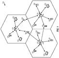
- FIG. 1 shows a wireless communication system 100, which may be an LTE system.
- System 100 may include a number of Node Bs 110 and other network entities.
- a Node B may be a station that communicates with the UEs and may also be referred to as an evolved Node B (eNB), a base station, an access point, etc.
- UEs 120 may be dispersed throughout the system, and each UE may be stationary or mobile.
- a UE may also be referred to as a mobile station, a terminal, an access terminal, a subscriber unit, a station, etc.
- a UE may be a cellular phone, a personal digital assistant (PDA), a wireless modem, a wireless communication device, a handheld device, a laptop computer, a cordless phone, a wireless local loop (WLL) station, etc.
- PDA personal digital assistant
- the system may support hybrid automatic retransmission (HARQ).
- HARQ hybrid automatic retransmission
- a Node B may send a transmission of data and may send one or more retransmissions until the data is decoded correctly by a recipient UE, or the maximum number of retransmissions has been sent, or some other termination condition is encountered.
- HARQ may improve reliability of data transmission.
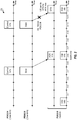
- FIG. 2 shows example downlink transmission by a Node B and example uplink transmission by a UE.
- the transmission timeline may be partitioned into units of subframes. Each subframe may have a particular duration, e.g., one millisecond (ms).
- the UE may periodically estimate the downlink channel quality for the Node B and may send CQI information on a physical uplink control channel (PUCCH) to the Node B.
- PUCCH physical uplink control channel
- the UE may send CQI information periodically in every sixth subframe, e.g., subframes t, t + 6, t + 12, etc.
- the Node B may use the CQI information and/or other information to select the UE for downlink transmission and to select a suitable transport format (e.g., a modulation and coding scheme) for the UE.
- the Node B may process a transport block in accordance with the selected transport format and obtain a codeword.
- a transport block may also be referred to as a packet, etc.
- the Node B may send control information on a physical downlink control channel (PDCCH) and a transmission of the codeword on a physical downlink shared channel (PDSCH) to the UE in sub frame t + 4.
- the control information may comprise the selected transport format, the resources used for the data transmission on the PDSCH, and/or other information.
- the UE may process the PDCCH to obtain the control information and may process the PDSCH in accordance with the control information to decode the codeword.
- the UE may generate ACK information, which may comprise an ACK if the codeword is decoded correctly or a NACK if the codeword is decoded in error.
- the UE may send the ACK information on the PUCCH in subframe t + 6.
- the Node B may send a retransmission of the codeword if a NACK is received and may send a transmission of a new codeword if an ACK is received.
- FIG. 2 shows an example in which the ACK information is delayed by two subframes from the codeword transmission. The ACK information may also be delayed by some other amount.
- the Node B may send control information on the PDCCH and a re/transmission of a codeword on the PDSCH in subframe t + 10.
- the UE may miss the control information sent on the PDCCH (e.g., decode the control information in error) and would then miss the data transmission sent on the PDSCH.
- the UE may then send DTX (i.e., nothing) for ACK information in subframe t + 12.
- the Node B may expect to receive CQI and ACK information in subframe t + 12.
- the Node B may receive DTX for the ACK information, interpret the DTX as NACK, and send a retransmission of the codeword.
- the UE may send CQI and/or ACK information on the PUCCH.
- the ACK information may convey whether each transport block sent by the Node B to the UE is decoded correctly or in error by the UE.
- the amount of ACK information to send by the UE may be dependent on the number of transport blocks sent to the UE.
- the ACK information may comprise one or two ACK bits depending on whether one or two transport blocks are sent to the UE. In other designs, the ACK information may comprise more ACK bits.
- the CQI information may convey the downlink channel quality estimated by the UE for the Node B.
- the CQI information may comprise one or more quantized values for a channel quality metric such as signal-to-noise ratio (SNR), signal-to-noise-and-interference ratio (SINR), etc.
- the CQI information may also comprise one or more transport formats determined based on the channel quality metric.
- the amount of CQI information to send by the UE may be dependent on various factors such as the number of spatial channels available for downlink transmission, the format for reporting the downlink channel quality, the desired granularity of the reported downlink channel quality, etc.
- the CQI information may comprise 4 to 11 bits. In other designs, the CQI information may comprise fewer or more bits.
- the UE may send only CQI information or both CQI and ACK information on the PUCCH in a given subframe.
- the UE may send CQI information at a periodic rate and in specific subframes, which may be known by both the UE and the Node B.
- the UE may send only CQI information when there is no ACK information to send, e.g., in subframe t in FIG. 2 .
- the UE may also send only CQI information when the UE misses the PDCCH and sends DTX for ACK information, e.g., in subframe t + 12 in FIG. 2 .
- the UE may send both CQI and ACK information when the UE receives the PDCCH and decodes the PDSCH, e.g., in subframe t + 6 in FIG. 2 .
- the UE may also send only ACK information, which is not shown in FIG. 2 .
- the UE may encode only CQI information or both CQI and ACK information in various manners. In general, it may be desirable for the UE to encode and send only CQI information or both CQI and ACK information such that the Node B can reliably receive the information sent by the UE.
- the UE may encode only CQI information or both CQI and ACK information based on a linear block code.
- the UE may order the different types of information to send such that the Node B can recover the information even in the presence of DTX of one type of information, as described below.
- the CQI information may comprise M bits, where M may be any suitable value and M ⁇ 11 in one design.
- the ACK information may comprise N bits, where N may also be any suitable value and N ⁇ 2 in one design. In one design, only CQI information or both CQI and ACK information may be encoded based on a (20, L) block code, which may be derived from a (32, 6) Reed-Muller code, where L ⁇ M + N.
- an (R, C) Reed-Muller code may be used to encode up to C information bits and generate R code bits.
- the (R, C) Reed-Muller code may be defined by an R ⁇ C generator matrix G R ⁇ C having R rows and C columns.
- a (32, 6) Reed-Muller code may be defined by a generator matrix G 32 ⁇ 6 , which may be generated based on equations (1) and (2).
- the 6 columns of generator matrix G 32 ⁇ 6 may be denoted as v 0 through v 5 .
- a (32, 21) second-order Reed-Muller code may be defined by a generator matrix G 32 ⁇ 21 containing the six columns of G 32 ⁇ 6 and 15 additional columns generated by linear combination of different possible pairs of columns of G 32 ⁇ 6 .
- the seventh column of G 32 ⁇ 21 may be generated based on v 0 and v 1
- the eighth column may be generated based on v 0 and v 2
- the last column may be generated based on v 4 and v 5 .
- the (20, L) block code may be obtained by taking 20 rows and L columns of the (32, 21) second-order Reed-Muller code, where L may be any suitable value.
- the (20, L) block code may be defined by a generator matrix G 20 ⁇ L having 20 rows and L columns. Each column of G 20 ⁇ L is a basis sequence of length 20 and may be used to encode one information bit.
- a message of K information bits may be defined based on only CQI information or both CQI and ACK information.
- the message may also be referred to as a word, input data, etc.
- CQI information may be mapped to M MSBs and ACK information may be mapped to N LSBs of the message, as follows:
- the (20, K) block code may be formed with the first K basis sequences or columns of the (20, L) block code.
- each information bit a k may be encoded by multiplying a k with each element M i,k of a basis sequence for that information bit to obtain an encoded basis sequence.
- K encoded basis sequences for the K information bits may be combined with modulo-2 addition to obtain an output bit sequence (or codeword) composed of coded bits b 0 through b 19 .
- M CQI bits may be encoded with a (20, M) block code formed by the first M basis sequences of the (20, L) block code. If both CQI and ACK information are sent, then M CQI bits and N ACK bits may be encoded with a (20, M+N) block code formed by the first M+N basis sequences of the (20, L) block code. The M CQI bits may be encoded with the first M basis sequences and the N ACK bits may be encoded with the next N basis sequences of the (20, L) block code.
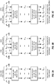
- FIG. 3A shows transmission of only CQI information in accordance with the coding and mapping designs described above.
- the UE may map M bits for CQI information to bits a 0 through a M-1 of a message, with a 0 being the MSB and a M-1 being the LSB.
- the UE may encode bits a 0 through a M-1 with the (20, M) block code formed by the first M basis sequences of the (20, L) block code and may obtain 20 code bits b 0 through b 19 .
- the UE may send the code bits on the PUCCH.
- the Node B may expect to receive only CQI information and may decode the PUCCH transmission in accordance with the (20, M) block code.
- the Node B may perform maximum likelihood decoding or may implement some other decoding algorithm.
- the Node B may obtain M decoded bits ⁇ 1 through ⁇ M-1 and may interpret these decoded bits as CQI bits.
- FIG. 3B shows transmission of both CQI and ACK information in accordance with the coding and mapping designs described above.
- the UE may map M bits for CQI information to bits a 0 through a M-1 and may map N bits for ACK information to bits a M through a M+N-1 of a message, with a 0 being the MSB and a M+N-1 being the LSB.
- the UE may encode bits a 0 through a M+N-1 with the (20, M+N) block code formed by the first M+N basis sequences of the (20, L) block code and may obtain code bits b 0 through b 19 .
- the UE may send the code bits on the PUCCH.
- the Node B may expect to receive both CQI and ACK information and may decode the PUCCH transmission in accordance with the (20, M+N) block code.
- the Node B may obtain M+N decoded bits ⁇ 1 through ⁇ M+N-1 .
- the Node B may interpret the first M decoded bits ⁇ 1 through ⁇ M-1 as CQI bits and may interpret the last N decoded bits ⁇ M through ⁇ M+N-1 as ACK bits.
- FIG. 3C shows transmission of CQI information and DTX for ACK information in accordance with the coding and mapping designs described above.
- the UE may miss the PDCCH and may send only CQI information by (i) mapping M bits for CQI information to bits a 0 through a M-1 of a message and (ii) encoding bits a 0 through a M-1 with the (20, M) block code, as shown in FIG. 3A .
- the code bits b 0 through b 19 in FIG. 3C are equal to the code bits b 0 through b 19 in FIG. 3A .
- the UE may send the code bits on the PUCCH.
- the Node B may expect to receive both CQI and ACK information and may decode the PUCCH transmission in accordance with the (20, M+N) block code.
- the Node B may obtain M+N decoded bits ⁇ 1 through ⁇ M+N-1 .
- the Node B may interpret the first M decoded bits ⁇ 1 through ⁇ M-1 as CQI bits and may interpret the last N decoded bits ⁇ M through ⁇ M+N-1 as ACK bits. Since the UE sent DTX for the N ACK bits, the Node B would receive NACKs for the ACK bits due to the mapping shown in equation (6).
- the coding and mapping designs described above and shown in FIGS. 3A to 3C may allow the Node B to correctly recover CQI information and properly respond to DTX even in a scenario in which the UE misses the PDCCH and transmits only CQI information using the (20, M) block code.
- transmitting M CQI bits using the (20, M) block code in FIG. 3A is equivalent to transmitting M CQI bits and N zeros using the (20, M+N) block code in FIG. 3C .
- the Node B may decode the PUCCH transmission using the (20, M+N) block code when the Node B expects to receive both CQI and ACK information and may obtain M+N decoded bits.
- the Node B may interpret the M decoded MSBs as being for CQI information and the N decoded LSBs as being for ACK information. If the UE transmits DTX for ACK information, then the Node B would obtain zeros for the N decoded LSBs (assuming correct decoding by the Node B). The Node B may interpret these zeros as NACKs and may send a retransmission to the UE, which would be the desired Node B response for the DTX from the UE.
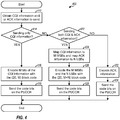
- FIG. 4 shows a design of a process 400 performed by the UE for sending feedback control information on the PUCCH.
- the UE may obtain CQI information and/or ACK information to send (block 412).
- the UE may determine whether only CQI information is being sent (block 414). If the answer is 'Yes', then the UE may encode M bits of the CQI information with the (20, M) block code (block 416) and may send the code bits on the PUCCH (block 418).
- the UE may determine whether both CQI and ACK information are being sent (block 422). If the answer is 'Yes', then the UE may map CQI information to M MSBs and may map ACK information to N LSBs of a message (block 424). The UE may then encode the M MSBs and the N LSBs with the (20, M+N) block code (block 426) and may send the code bits on the PUCCH (block 428).
- the UE may encode the ACK information (block 432) and may send the code bits on the PUCCH (block 434).
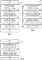
- FIG. 5 shows a design of a process 500 performed by the Node B to receive feedback control information from the UE.
- the Node B may receive a transmission on the PUCCH from the UE (block 512).
- the Node B may determine whether only CQI information is expected from the UE (block 514). If the answer is 'Yes' for block 514, which may be the case if no data has been sent to the UE, then the Node B may decode the received transmission based on the (20, M) block code to obtain M decoded bits (block 516).
- the Node B may provide these M decoded bits as M CQI bits (block 518).
- the Node B may determine whether both CQI and ACK information are expected from the UE (block 522). If the answer is 'Yes' for block 522, which may be the case if data has been sent to the UE, then the Node B may decode the received transmission based on the (20, M+N) block code to obtain M+N decoded bits (block 524). The Node B may provide the M MSBs of the decoded bits as M CQI bits (block 526) and may provide the N LSBs of the decoded bits as N ACK bits (block 528). The Node B may interpret zeros for the ACK bits as NACK/DTX (block 530). If the answer is 'No' for block 522, then the Node B may decode the received transmission to obtain ACK bits (block 532).
- the coding and mapping designs shown in FIGS. 3A to 5 may avoid decoding errors due to transmission of DTX for ACK information. Decoding errors may occur in an alternate design in which ACK information is mapped to N MSBs and CQI information is mapped to M LSBs (which is opposite of the coding design shown in FIGS. 3A to 3C ). In this alternate design, if only CQI information is sent, then M CQI bits may be encoded with the first M basis sequences of the (20, L) block code. If both CQI and ACK information are sent, then N ACK bits may be encoded with the first N basis sequences and M CQI bits may be encoded with the next M basis sequences of the (20, L) block code.
- the UE may miss the PDCCH and may send only CQI information using the (20, M) block code formed by the first M basis sequences of the (20, L) block code.
- the Node B may expect both CQI and ACK information and may decode based on the (20, N+M) block code formed by the first N+M basis sequences of the (20, L) block code.
- the Node B may obtain N decoded bits for the first N basis sequences and may interpret these N decoded bits as being for ACK information.
- the Node B may obtain M decoded bits for the next M basis sequences and may interpret these M decoded bits as being for CQI information.
- the Node B may obtain erroneous ACK information since the N decoded bits interpreted as ACK bits are actually N MSBs of the CQI information sent by the UE.
- the Node B may also obtain erroneous CQI information since the M decoded bits interpreted as CQI bits are actually M-N LSBs of the CQI information and N bits of DTX.
- the design in FIGS. 3A to 5 may avoid these errors.
- FIG. 6A shows plots of decoding performance for the first and second mapping schemes for a scenario with 5 CQI bits and 1 ACK bit using a (20, 6) block code formed with the first six basis sequences of the (20, 13) block code.
- the horizontal axis represents received signal quality, which is given in energy-per-symbol-to-total-noise ratio (Es/Nt).
- the vertical axis represents block error rate (BLER).
- Es/Nt energy-per-symbol-to-total-noise ratio
- BLER block error rate
- FIG. 6B shows plots of decoding performance for the first and second mapping schemes for a scenario with 8 CQI bits and 2 ACK bit using a (20, 10) block code formed with the first ten basis sequences of the (20, 13) block code.
- decoding performance for CQI information is shown by a plot 632
- decoding performance for ACK information is shown by a plot 634.
- decoding performance for CQI information is shown by a plot 642
- decoding performance for ACK information is shown by a plot 644.
- mapping the ACK information to LSBs or MSBs provide similar decoding performance using the (20, 13) block code in an additive white Gaussian noise (AWGN) channel.
- AWGN additive white Gaussian noise
- the computer simulations suggest that the (20, 13) block code provides equivalent protection for all information bits and that mapping ACK information to either the MSBs or LSBs minimally affect decoding performance.
- the techniques may be used to send first information and second information, each of which may be any type of information.
- the first information may be mapped to M MSBs, where M ⁇ 1.
- the second information may be mapped to N LSBs if it is sent, where N ⁇ 1.
- the M MSBs and the N LSBs may be encoded with a block code comprising a first sub-code for the M MSBs and a second sub-code for the N LSBs.
- the first sub-code may be equal to the block code used to encode only the first information. This may allow a receiver to recover the first information regardless of whether it is sent alone or with the second information.
- the second information may also be defined such that DTX of the second information would result in proper action by the receiver.
- FIG. 7 shows a design of a process 700 for sending information in a communication system.
- Process 700 may be performed by a UE (as described below) or by some other entity.
- the UE may map first information (e.g., CQI information) to M MSBs of a message, where M may be one or greater (block 712).
- the UE may map second information (e.g., ACK information) to N LSBs of the message if the second information is sent, where N may be one or greater (block 714).
- the first information may be sent alone or with the second information in the message.
- the second information may be sent with the first information or not sent in the message.
- the UE may encode the message with a block code to obtain an output bit sequence (block 716).
- the UE may send the output bit sequence on the PUCCH (block 718).
- FIG. 8 shows a design of block 716 in FIG. 7 .
- the block code may be derived based on a Reed-Muller code and/or may comprise a plurality of basis sequences for a plurality of information bits.
- the UE may encode the M MSBs of the message with the first M basis sequences of the block code (block 812).
- the UE may encode the N LSBs of the message with the next N basis sequences of the block code if the second information is sent (block 814).
- the message may comprise M bits and may be encoded with the first M basis sequences of the block code. If both CQI and ACK information are sent, then the message may comprise M plus N bits and may be encoded with the first M plus N basis sequences of the block code.
- the UE may set each of N ACK bits to a first value (e.g., '1') for an ACK or to a second value (e.g., '0') for a NACK. The second value may also be used for DTX of the ACK information.
- the ACK information may comprise the N ACK bits.
- FIG. 9 shows a design of an apparatus 900 for sending information in a communication system.
- Apparatus 900 includes a module 912 to map first information to M MSBs of a message, a module 914 to map second information to N LSBs of the message if the second information is sent, a module 916 to encode the message with a block code to obtain an output bit sequence, and a module 918 to send the output bit sequence on the PUCCH.
- FIG. 10 shows a design of a process 1000 for sending information in a communication system.
- Process 1000 may be performed by a UE (as described below) or by some other entity.
- the UE may encode first information (e.g., CQI information) based on a first block code if only the first information is sent (block 1012).
- the UE may encode the first information and second information (e.g., ACK information) based on a second block code if both the first and second information are sent (block 1014).
- the second block code may comprise a first sub-code for the first information and a second sub-code for the second information.
- the first sub-code may correspond to the first block code.
- the first block code and the first sub-code may comprise the first M basis sequences of a base block code
- the second sub-code may comprise the next N basis sequences of the base block code
- the second block code may comprise the first M plus N basis sequences of the base block code
- the UE may set each of N bits to a first value for an ACK or to a second value for a NACK, where N is one or greater.
- the second value may also be used for DTX of the second information.
- the second information may comprise the N bits.
- FIG. 11 shows a design of an apparatus 1100 for sending information in a communication system.
- Apparatus 1100 includes a module 1112 to encode first information (e.g., CQI information) based on a first block code if only the first information is sent, and a module 1114 to encode the first information and second information (e.g., ACK information) based on a second block code if both the first and second information are sent.
- the second block code may comprise a first sub-code for the first information and a second sub-code for the second information.
- the first sub-code may correspond to the first block code.
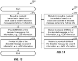
- FIG. 12 shows a design of a process 1200 for receiving information in a communication system.
- Process 1200 may be performed by a Node B (as described below) or by some other entity.
- the Node B may decode a received transmission based on a block code to obtain a decoded message comprising multiple bits (block 1212).
- the Node B may provide M MSBs of the decoded message as first information (e.g., CQI information), where M may be one or greater (block 1214).
- the Node B may provide N LSBs of the decoded message as second information (e.g., ACK information), where N may be one or greater (block 1216).
- the received transmission may comprise only the first information or both the first and second information.
- the block code may be derived based on a Reed-Muller code and/or may comprise a plurality of basis sequences for a plurality of information bits.
- the Node B may decode the received transmission based on the first M plus N basis sequences of the block code to obtain the decoded message.
- the M MSBs of the decoded message may be obtained based on the first M basis sequences of the block code.
- the N LSBs of the decoded message may be obtained based on the next N basis sequences of the block code.
- the Node B may provide an ACK if the bit has a first value or a NACK if the bit has a second value.
- the second value may also be used for DTX of the ACK information.
- the Node B may obtain the received transmission on the PUCCH.
- the received transmission may comprise a first output bit sequence if only CQI information is sent and may comprise a second output bit sequence if both CQI and ACK information are sent.
- the first output bit sequence may be obtained by encoding M bits of the CQI information with the first M basis sequences of the block code.
- the second output bit sequence may be obtained by encoding (i) M bits of the CQI information with the first M basis sequences of the block code and (ii) N bits of the ACK information with the next N basis sequences of the block code.
- FIG. 13 shows a design of an apparatus 1300 for receiving information in a communication system.
- Apparatus 1300 includes a module 1312 to decode a received transmission based on a block code to obtain a decoded message comprising multiple bits, a module 1314 to provide M MSBs of the decoded message as first information, and a module 1316 to provide N LSBs of the decoded message as second information.
- the received transmission may comprise only the first information or both the first and second information.
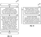
- FIG. 14 shows a design of a process 1400 for receiving information in a communication system.
- Process 1400 may be performed by a Node B (as described below) or by some other entity.
- the Node B may decode a received transmission based on a first block code if only first information (e.g., CQI information) is expected from the received transmission (block 1412).
- the Node B may decode the received transmission based on a second block code if both the first information and second information (e.g., ACK information) are expected from the received transmission (block 1414).
- the second block code may comprise a first sub-code for the first information and a second sub-code for the second information.
- the first sub-code may correspond to the first block code.
- the Node B may provide an ACK if the bit has a first value or a NACK if the bit has a second value.
- the second value may also be used for DTX of the second information.
- FIG. 15 shows a design of an apparatus 1500 for receiving information in a communication system.
- Apparatus 1500 includes a module 1512 to decode a received transmission based on a first block code if only first information (e.g., CQI information) is expected from the received transmission, and a module 1514 to decode the received transmission based on a second block code if both the first information and second information (e.g., ACK information) are expected from the received transmission.
- the second block code may comprise a first sub-code for the first information and a second sub-code for the second information.
- the first sub-code may correspond to the first block code.
- the modules in FIGS. 9 , 11 , 13 and 15 may comprise processors, electronics devices, hardware devices, electronics components, logical circuits, memories, software codes, firmware codes, etc., or any combination thereof.
- FIG. 16 shows a block diagram of a design of a Node B 110 and a UE 120, which may be one of the Node Bs and one of the UEs in FIG. 1 .
- Node B 110 is equipped with T antennas 1634a through 1634t
- UE 120 is equipped with R antennas 1652a through 1652r, where in general T ⁇ 1 and R ⁇ 1.
- a transmit processor 1620 may receive data for one or more UEs from a data source 1612, process (e.g., encode, interleave, and modulate) the data for each UE based on one or more transport formats selected for that UE, and provide data symbols for all UEs. Transmit processor 1620 may also process control information from a controller/processor 1640 and provide control symbols.
- a transmit (TX) multiple-input multiple-output (MIMO) processor 1630 may multiplex the data symbols, the control symbols, and/or pilot symbols.
- TX MIMO processor 1630 may perform spatial processing (e.g., precoding) on the multiplexed symbols, if applicable, and provide T output symbol streams to T modulators (MODs) 1632a through 1632t.
- Each modulator 1632 may process a respective output symbol stream (e.g., for OFDM) to obtain an output sample stream.
- Each modulator 1632 may further process (e.g., convert to analog, amplify, filter, and upconvert) the output sample stream to obtain a downlink signal.
- T downlink signals from modulators 1632a through 1632t may be transmitted via T antennas 1634a through 1634t, respectively.
- antennas 1652a through 1652r may receive the downlink signals from Node B 110 and provide received signals to demodulators (DEMODs) 1654a through 1654r, respectively.
- Each demodulator 1654 may condition (e.g., filter, amplify, downconvert, and digitize) a respective received signal to obtain received samples.
- Each demodulator 1654 may further process the received samples (e.g., for OFDM) to obtain received symbols.
- a MIMO detector 1656 may obtain received symbols from all R demodulators 1654a through 1654r, perform MIMO detection on the received symbols if applicable, and provide detected symbols.
- a receive processor 1658 may process (e.g., demodulate, deinterleave, and decode) the detected symbols, provide decoded control information to a controller/processor 1680, and provide decoded data for UE 120 to a data sink 1660.
- data from a data source 1662 and control information (e.g., CQI information, ACK information, etc.) from controller/processor 1680 may be processed by a transmit processor 1664, precoded by a TX MIMO processor 1666 if applicable, conditioned by modulators 1654a through 1654r, and transmitted to Node B 110.
- the uplink signals from UE 120 may be received by antennas 1634, conditioned by demodulators 1632, processed by a MIMO detector 1636 if applicable, and further processed by a receive processor 1638 to obtain the data and control information transmitted by UE 120.
- Controllers/processors 1640 and 1680 may direct the operation at Node B 110 and UE 120, respectively.
- Processor 1680 and/or other processors/modules at UE 120 may perform or direct process 400 in FIG. 4 , process 700 in FIG. 7 , process 716 in FIG. 8 , process 1000 in FIG. 10 , and/or other processes for the techniques described herein.
- Processor 1640 and/or other modules at Node B 110 (and also processor 1680 and/or other processors/modules at UE 120) may perform or direct process 500 in FIG. 5 , process 1200 in FIG. 12 , process 1400 in FIG.
- Memories 1642 and 1682 may store data and program codes for Node B 110 and UE 120, respectively.
- a scheduler 1644 may schedule UEs for downlink and/or uplink transmission and may provide assignments of resources for the scheduled UEs.
- DSP digital signal processor
- ASIC application specific integrated circuit
- FPGA field programmable gate array
- a general-purpose processor may be a microprocessor, but in the alternative, the processor may be any conventional processor, controller, microcontroller, or state machine.
- a processor may also be implemented as a combination of computing devices, e.g., a combination of a DSP and a microprocessor, a plurality of microprocessors, one or more microprocessors in conjunction with a DSP core, or any other such configuration.
- a software module may reside in RAM memory, flash memory, ROM memory, EPROM memory, EEPROM memory, registers, hard disk, a removable disk, a CD-ROM, or any other form of storage medium known in the art.
- An exemplary storage medium is coupled to the processor such that the processor can read information from, and write information to, the storage medium.
- the storage medium may be integral to the processor.
- the processor and the storage medium may reside in an ASIC.
- the ASIC may reside in a user terminal.
- the processor and the storage medium may reside as discrete components in a user terminal.
- the functions described may be implemented in hardware, software, firmware, or any combination thereof. If implemented in software, the functions may be stored on or transmitted over as one or more instructions or code on a computer-readable medium.
- Computer-readable media includes both computer storage media and communication media including any medium that facilitates transfer of a computer program from one place to another.
- a storage media may be any available media that can be accessed by a general purpose or special purpose computer.
- such computer-readable media can comprise RAM, ROM, EEPROM, CD-ROM or other optical disk storage, magnetic disk storage or other magnetic storage devices, or any other medium that can be used to carry or store desired program code means in the form of instructions or data structures and that can be accessed by a general-purpose or special-purpose computer, or a general-purpose or special-purpose processor. Also, any connection is properly termed a computer-readable medium.
- Disk and disc includes compact disc (CD), laser disc, optical disc, digital versatile disc (DVD), floppy disk and blu-ray disc where disks usually reproduce data magnetically, while discs reproduce data optically with lasers. Combinations of the above should also be included within the scope of computer-readable media.
Landscapes
- Engineering & Computer Science (AREA)
- Computer Networks & Wireless Communication (AREA)
- Signal Processing (AREA)
- Quality & Reliability (AREA)
- Mobile Radio Communication Systems (AREA)
- Detection And Prevention Of Errors In Transmission (AREA)
- Error Detection And Correction (AREA)
Applications Claiming Priority (3)
| Application Number | Priority Date | Filing Date | Title |
|---|---|---|---|
| US4070008P | 2008-03-30 | 2008-03-30 | |
| US12/407,161 US9030948B2 (en) | 2008-03-30 | 2009-03-19 | Encoding and decoding of control information for wireless communication |
| PCT/US2009/038679 WO2009123935A2 (en) | 2008-03-30 | 2009-03-27 | Encoding and decoding of control information for wireless communication |
Publications (2)
| Publication Number | Publication Date |
|---|---|
| EP2260604A2 EP2260604A2 (en) | 2010-12-15 |
| EP2260604B1 true EP2260604B1 (en) | 2019-08-14 |
Family
ID=41117127
Family Applications (1)
| Application Number | Title | Priority Date | Filing Date |
|---|---|---|---|
| EP09728517.5A Active EP2260604B1 (en) | 2008-03-30 | 2009-03-27 | Encoding and decoding of control information for wireless communication |
Country Status (18)
| Country | Link |
|---|---|
| US (1) | US9030948B2 (zh) |
| EP (1) | EP2260604B1 (zh) |
| JP (5) | JP2011518496A (zh) |
| KR (1) | KR101095162B1 (zh) |
| CN (2) | CN105227270B (zh) |
| AU (1) | AU2009231940B2 (zh) |
| BR (1) | BRPI0909237B1 (zh) |
| CA (1) | CA2718158C (zh) |
| ES (1) | ES2754815T3 (zh) |
| HU (1) | HUE045959T2 (zh) |
| IL (1) | IL208074A (zh) |
| MX (1) | MX2010010549A (zh) |
| MY (1) | MY156124A (zh) |
| RU (1) | RU2464713C2 (zh) |
| SG (1) | SG189719A1 (zh) |
| TW (1) | TWI492565B (zh) |
| UA (1) | UA100409C2 (zh) |
| WO (1) | WO2009123935A2 (zh) |
Families Citing this family (42)
| Publication number | Priority date | Publication date | Assignee | Title |
|---|---|---|---|---|
| KR101646249B1 (ko) * | 2008-08-11 | 2016-08-16 | 엘지전자 주식회사 | 무선 통신 시스템에서 정보 전송 방법 및 장치 |
| KR101597573B1 (ko) * | 2008-08-11 | 2016-02-25 | 엘지전자 주식회사 | 제어정보의 상향링크 전송 방법 |
| KR101603338B1 (ko) | 2008-08-11 | 2016-03-15 | 엘지전자 주식회사 | 무선 통신 시스템에서 정보 전송 방법 및 장치 |
| KR101571566B1 (ko) * | 2008-08-11 | 2015-11-25 | 엘지전자 주식회사 | 무선 통신 시스템에서 제어신호 전송 방법 |
| KR20100019947A (ko) * | 2008-08-11 | 2010-02-19 | 엘지전자 주식회사 | 무선 통신 시스템에서 정보 전송 방법 |
| CN104218985B (zh) | 2008-11-14 | 2017-12-08 | Lg电子株式会社 | 用于在无线通信系统中发送信号的方法和装置 |
| EP2357735B1 (en) | 2008-11-14 | 2016-11-09 | LG Electronics Inc. | Method and apparatus for information transmission in wireless communication system |
| KR20100091876A (ko) | 2009-02-11 | 2010-08-19 | 엘지전자 주식회사 | 다중안테나 전송을 위한 단말 동작 |
| CN102598724B (zh) | 2009-08-25 | 2015-06-03 | 交互数字专利控股公司 | 用于管理群组通信的方法和设备 |
| KR101802754B1 (ko) * | 2010-01-17 | 2017-11-29 | 엘지전자 주식회사 | 무선 통신 시스템에서 제어 정보의 전송 방법 및 장치 |
| KR101730369B1 (ko) | 2010-01-17 | 2017-04-26 | 엘지전자 주식회사 | 무선 통신 시스템에서 제어 정보의 전송 방법 및 장치 |
| KR101814394B1 (ko) | 2010-01-17 | 2018-01-03 | 엘지전자 주식회사 | 무선 통신 시스템에서 제어 정보의 전송 방법 및 장치 |
| KR101733489B1 (ko) * | 2010-01-17 | 2017-05-24 | 엘지전자 주식회사 | 무선 통신 시스템에서 제어 정보의 전송 방법 및 장치 |
| US8855076B2 (en) | 2010-01-17 | 2014-10-07 | Lg Electronics Inc. | Method and apparatus for transmitting control information in wireless communication system |
| US10453157B2 (en) | 2010-01-22 | 2019-10-22 | Deka Products Limited Partnership | System, method, and apparatus for electronic patient care |
| US9636455B2 (en) | 2011-12-21 | 2017-05-02 | Deka Products Limited Partnership | System, method, and apparatus for estimating liquid delivery |
| US8648016B2 (en) * | 2010-02-08 | 2014-02-11 | Robert Bosch Gmbh | Array with extended dynamic range and associated method |
| EP3447959B1 (en) * | 2010-02-11 | 2020-07-15 | Samsung Electronics Co., Ltd. | Method for indicating a dm-rs antenna port in a wireless communication system |
| KR101688551B1 (ko) * | 2010-02-11 | 2016-12-22 | 삼성전자주식회사 | 무선 통신 시스템에서 사용자에 특정한 dmrs 안테나 포트를 지시하는 방법 |
| ES2681020T3 (es) | 2010-03-22 | 2018-09-11 | Samsung Electronics Co., Ltd | Control de multiplexación e información de datos procedentes de un equipo de usuario en un canal físico de datos |
| KR101684867B1 (ko) * | 2010-04-07 | 2016-12-09 | 삼성전자주식회사 | 공간 다중화 이득을 이용한 제어 정보 송수신 방법 |
| US8605669B2 (en) * | 2010-05-06 | 2013-12-10 | Telefonaktiebolaget Lm Ericsson (Publ) | System and method for signaling control information in a mobile communication network |
| US20130107985A1 (en) * | 2010-06-01 | 2013-05-02 | Lg Electronics Inc. | Method for transmitting control information in wireless communication system, and apparatus for same |
| AU2011324151B2 (en) * | 2010-11-03 | 2016-02-25 | Samsung Electronics Co., Ltd. | Method and apparatus for coding of HARQ-ACK transmission in TDD systems with DownLink carrier aggregation |
| CN103370970B (zh) | 2010-11-03 | 2016-11-09 | 三星电子株式会社 | 具有载波聚合的下行链路的tdd系统中的harq-ack信息生成及harq-ack信号功率控制 |
| EP2640119B1 (en) * | 2010-11-09 | 2020-06-17 | Sharp Kabushiki Kaisha | Mobile station device, base station device, wireless communication system, wireless communication method, and integrated circuit |
| CN102036302B (zh) * | 2011-01-06 | 2014-01-01 | 华为技术有限公司 | 一种资源管理的方法、基站和系统 |
| KR101595198B1 (ko) * | 2011-09-23 | 2016-02-17 | 엘지전자 주식회사 | 무선 통신 시스템에서 상향링크 제어 정보 전송 방법 및 장치 |
| WO2013105836A1 (ko) * | 2012-01-15 | 2013-07-18 | 엘지전자 주식회사 | 상향링크를 통해 제어정보를 송신하는 방법 및 장치 |
| US9674822B2 (en) | 2012-02-22 | 2017-06-06 | Lg Electronics Inc. | Method and apparatus for transmitting control information |
| US9526091B2 (en) * | 2012-03-16 | 2016-12-20 | Intel Corporation | Method and apparatus for coordination of self-optimization functions in a wireless network |
| WO2015068960A1 (ko) * | 2013-11-07 | 2015-05-14 | 엘지전자 주식회사 | 보안 데이터 전송 방법 및 그 수신 방법 |
| KR102147679B1 (ko) * | 2014-08-13 | 2020-08-25 | 삼성전자 주식회사 | 압축 후 전달 기법을 사용하는 릴레이 무선 통신 시스템에서 복합 자동 재전송 방법 및 장치 |
| US10110290B2 (en) * | 2015-08-13 | 2018-10-23 | Electronics And Telecommunications Research Institute | Terminal for periodically transmitting CSI feedback information |
| WO2017075825A1 (zh) | 2015-11-06 | 2017-05-11 | 广东欧珀移动通信有限公司 | 一种数据存储的方法、终端设备及基站 |
| RU168557U1 (ru) * | 2016-08-08 | 2017-02-08 | Федеральное государственное учреждение "Федеральный исследовательский центр "Информатика и управление" Российской академии наук" (ФИЦ ИУ РАН) | Устройство декодирования управляющей информации |
| US11356217B2 (en) | 2016-11-04 | 2022-06-07 | Telefonaktiebolaget Lm Ericsson (Publ) | ACK/NACK transmission strategies |
| US10972213B2 (en) | 2016-11-04 | 2021-04-06 | Telefonaktiebolaget Lm Ericsson (Publ) | Simultaneous transmission of periodic CQI and ACK/NACK |
| CN108811163A (zh) | 2017-05-04 | 2018-11-13 | 株式会社Ntt都科摩 | 数据检测方法和用户设备 |
| US10587388B2 (en) | 2017-08-22 | 2020-03-10 | Cavium, Llc. | Method and apparatus for uplink control channel detection |
| US10448377B2 (en) | 2017-09-28 | 2019-10-15 | Cavium, Llc | Methods and apparatus for control channel detection in an uplink shared channel |
| US11457502B2 (en) * | 2021-02-09 | 2022-09-27 | Hong Kong Applied Science And Technology Research Institute Co., Ltd | Method and device for detecting partial discontinuous transmission (DTX) using channel estimation data |
Family Cites Families (25)
| Publication number | Priority date | Publication date | Assignee | Title |
|---|---|---|---|---|
| KR100469711B1 (ko) * | 2001-01-18 | 2005-02-02 | 삼성전자주식회사 | 이동통신시스템에서 역방향 송신 제어 장치 및 방법 |
| KR100837351B1 (ko) | 2002-04-06 | 2008-06-12 | 엘지전자 주식회사 | 이동통신 시스템의 무선링크 파라미터 갱신 방법 |
| TWI259674B (en) * | 2002-05-07 | 2006-08-01 | Interdigital Tech Corp | Method and apparatus for reducing transmission errors in a third generation cellular system |
| DE60216269T2 (de) | 2002-08-06 | 2007-05-10 | Mitsubishi Electric Information Technology Centre Europe B.V. | Übertragungsqualitätsberichtverfahren |
| US7227854B2 (en) * | 2002-09-06 | 2007-06-05 | Samsung Electronics Co., Ltd. | Apparatus and method for transmitting CQI information in a CDMA communication system employing an HSDPA scheme |
| US7418053B2 (en) | 2004-07-30 | 2008-08-26 | Rearden, Llc | System and method for distributed input-distributed output wireless communications |
| US20060039330A1 (en) * | 2004-07-26 | 2006-02-23 | Interdigital Technology Corporation | High speed downlink packet access co-processor for upgrading the capabilities of an existing modem host |
| KR100651343B1 (ko) | 2004-09-15 | 2006-11-29 | 삼성전자주식회사 | 이동통신 시스템에서 전송 정보의 부호화/복호화 방법 및장치 |
| US7499474B2 (en) * | 2005-04-13 | 2009-03-03 | Nokia Corporation | Efficient HARQ control and channel quality feedback reporting for multicarrier systems |
| US8094595B2 (en) * | 2005-08-26 | 2012-01-10 | Qualcomm Incorporated | Method and apparatus for packet communications in wireless systems |
| US8649362B2 (en) * | 2005-11-02 | 2014-02-11 | Texas Instruments Incorporated | Methods for determining the location of control channels in the uplink of communication systems |
| WO2007078146A1 (en) | 2006-01-06 | 2007-07-12 | Samsung Electronics Co., Ltd. | Method and apparatus for transmitting/receiving uplink signaling information in a single carrier fdma system |
| US8374161B2 (en) * | 2006-07-07 | 2013-02-12 | Qualcomm Incorporated | Method and apparatus for sending data and control information in a wireless communication system |
| JP2010506495A (ja) | 2006-10-02 | 2010-02-25 | インターデイジタル テクノロジー コーポレーション | チャネル品質インジケータビットおよびプリコーディング制御情報ビットを符号化するための方法および装置 |
| KR100811843B1 (ko) * | 2006-10-27 | 2008-03-10 | 삼성전자주식회사 | 광대역 부호분할 다중접속 통신시스템에서 고속공통제어채널 통신 장치 및 방법 |
| US20080219370A1 (en) * | 2007-03-06 | 2008-09-11 | Texas Instruments Incorporated | User equipment feedback structures for mimo ofdma |
| JP5206921B2 (ja) * | 2007-03-16 | 2013-06-12 | 日本電気株式会社 | 移動無線システムにおけるリソース割当制御方法および装置 |
| US9294231B2 (en) | 2007-03-17 | 2016-03-22 | Qualcomm Incorporated | Configurable acknowledgement processing in a wireless communication system |
| MY148998A (en) * | 2007-04-30 | 2013-06-28 | Interdigital Tech Corp | Feedback signaling error detection and checking in mimo wireless communication systems |
| WO2009064122A1 (en) * | 2007-11-18 | 2009-05-22 | Lg Electronics Inc. | Methods of joint coding in mobile communication system |
| WO2009082146A2 (en) | 2007-12-24 | 2009-07-02 | Lg Electronics Inc. | Channel coding method of variable length information using block code |
| EP2245784A4 (en) * | 2008-02-11 | 2012-05-09 | Zte Usa Inc | METHOD AND SYSTEM FOR THE JOINT CODING OF MULTIPLE INDEPENDENT INFORMATION NEWS |
| KR101253190B1 (ko) * | 2008-08-08 | 2013-04-10 | 엘지전자 주식회사 | 무선 통신 시스템에서 채널 품질 정보 보고 방법 및 상기 채널 품질 정보에 따라 무선 자원을 할당하는 방법 |
| US8553627B2 (en) * | 2009-10-02 | 2013-10-08 | Sharp Laboratories Of America, Inc. | Transmission diversity scheme on physical uplink control channel (PUCCH) with ACK/NACK differentiation |
| KR101362116B1 (ko) * | 2010-07-29 | 2014-02-12 | 한국전자통신연구원 | 사용자 기기 모뎀을 위한 물리 상향링크 공유 채널 인코더 및 그것의 인코딩 방법 |
-
2009
- 2009-03-19 US US12/407,161 patent/US9030948B2/en active Active
- 2009-03-27 CN CN201510683846.4A patent/CN105227270B/zh active Active
- 2009-03-27 MX MX2010010549A patent/MX2010010549A/es active IP Right Grant
- 2009-03-27 RU RU2010144508/08A patent/RU2464713C2/ru active
- 2009-03-27 AU AU2009231940A patent/AU2009231940B2/en active Active
- 2009-03-27 MY MYPI2010004235A patent/MY156124A/en unknown
- 2009-03-27 BR BRPI0909237-4A patent/BRPI0909237B1/pt active IP Right Grant
- 2009-03-27 CA CA2718158A patent/CA2718158C/en active Active
- 2009-03-27 WO PCT/US2009/038679 patent/WO2009123935A2/en active Application Filing
- 2009-03-27 HU HUE09728517A patent/HUE045959T2/hu unknown
- 2009-03-27 CN CN2009801108913A patent/CN101981856A/zh active Pending
- 2009-03-27 UA UAA201012891A patent/UA100409C2/ru unknown
- 2009-03-27 JP JP2011503060A patent/JP2011518496A/ja active Pending
- 2009-03-27 SG SG2013023346A patent/SG189719A1/en unknown
- 2009-03-27 EP EP09728517.5A patent/EP2260604B1/en active Active
- 2009-03-27 ES ES09728517T patent/ES2754815T3/es active Active
- 2009-03-27 KR KR1020107024575A patent/KR101095162B1/ko active IP Right Grant
- 2009-03-30 TW TW098110484A patent/TWI492565B/zh active
-
2010
- 2010-09-07 IL IL208074A patent/IL208074A/en active IP Right Grant
-
2013
- 2013-11-11 JP JP2013233561A patent/JP2014075810A/ja not_active Withdrawn
-
2015
- 2015-11-24 JP JP2015228822A patent/JP2016054532A/ja not_active Withdrawn
-
2017
- 2017-12-01 JP JP2017231978A patent/JP2018085732A/ja not_active Withdrawn
-
2019
- 2019-09-10 JP JP2019164325A patent/JP7086041B2/ja active Active
Non-Patent Citations (1)
| Title |
|---|
| "3rd Generation Partnership Project; Technical Specification Group Radio Access Network; Evolved Universal Terrestrial Radio Access (E-UTRA); Multiplexing and channel coding (Release 8)", 3GPP STANDARD; 3GPP TS 36.212, 3RD GENERATION PARTNERSHIP PROJECT (3GPP), MOBILE COMPETENCE CENTRE ; 650, ROUTE DES LUCIOLES ; F-06921 SOPHIA-ANTIPOLIS CEDEX ; FRANCE, no. V8.2.0, 1 March 2008 (2008-03-01), pages 1 - 38, XP050377548 * |
Also Published As
Similar Documents
| Publication | Publication Date | Title |
|---|---|---|
| EP2260604B1 (en) | Encoding and decoding of control information for wireless communication | |
| EP2294743B1 (en) | Bundling of ack information in a wireless communication system | |
| KR101105507B1 (ko) | 무선 통신 시스템에서의 ack 및 cqi 정보의 보고 | |
| US8467367B2 (en) | Multiplexing and transmission of traffic data and control information in a wireless communication system | |
| US20090313516A1 (en) | Enhanced hybrid automatic repeat request for long term evolution | |
| US8121096B2 (en) | Method and apparatus for circular buffer-based rate matching and burst multiplexing for packet data transmission in a communication system | |
| US20120084618A1 (en) | Jointly encoding a scheduling request indicator and acknowledgments/negative acknowledgments | |
| RU2461132C2 (ru) | Сообщение отчета об информации ack и cqi в системе беспроводной связи | |
| KR20080112733A (ko) | 이동 통신 시스템에서 채널 정보 송수신 및 채널 부호화 |
Legal Events
| Date | Code | Title | Description |
|---|---|---|---|
| PUAI | Public reference made under article 153(3) epc to a published international application that has entered the european phase |
Free format text: ORIGINAL CODE: 0009012 |
|
| 17P | Request for examination filed |
Effective date: 20101011 |
|
| AK | Designated contracting states |
Kind code of ref document: A2 Designated state(s): AT BE BG CH CY CZ DE DK EE ES FI FR GB GR HR HU IE IS IT LI LT LU LV MC MK MT NL NO PL PT RO SE SI SK TR |
|
| AX | Request for extension of the european patent |
Extension state: AL BA RS |
|
| DAX | Request for extension of the european patent (deleted) | ||
| 17Q | First examination report despatched |
Effective date: 20130222 |
|
| STAA | Information on the status of an ep patent application or granted ep patent |
Free format text: STATUS: EXAMINATION IS IN PROGRESS |
|
| GRAP | Despatch of communication of intention to grant a patent |
Free format text: ORIGINAL CODE: EPIDOSNIGR1 |
|
| STAA | Information on the status of an ep patent application or granted ep patent |
Free format text: STATUS: GRANT OF PATENT IS INTENDED |
|
| INTG | Intention to grant announced |
Effective date: 20181207 |
|
| GRAS | Grant fee paid |
Free format text: ORIGINAL CODE: EPIDOSNIGR3 |
|
| GRAJ | Information related to disapproval of communication of intention to grant by the applicant or resumption of examination proceedings by the epo deleted |
Free format text: ORIGINAL CODE: EPIDOSDIGR1 |
|
| GRAL | Information related to payment of fee for publishing/printing deleted |
Free format text: ORIGINAL CODE: EPIDOSDIGR3 |
|
| STAA | Information on the status of an ep patent application or granted ep patent |
Free format text: STATUS: EXAMINATION IS IN PROGRESS |
|
| GRAP | Despatch of communication of intention to grant a patent |
Free format text: ORIGINAL CODE: EPIDOSNIGR1 |
|
| STAA | Information on the status of an ep patent application or granted ep patent |
Free format text: STATUS: GRANT OF PATENT IS INTENDED |
|
| INTC | Intention to grant announced (deleted) | ||
| INTG | Intention to grant announced |
Effective date: 20190401 |
|
| GRAA | (expected) grant |
Free format text: ORIGINAL CODE: 0009210 |
|
| STAA | Information on the status of an ep patent application or granted ep patent |
Free format text: STATUS: THE PATENT HAS BEEN GRANTED |
|
| AK | Designated contracting states |
Kind code of ref document: B1 Designated state(s): AT BE BG CH CY CZ DE DK EE ES FI FR GB GR HR HU IE IS IT LI LT LU LV MC MK MT NL NO PL PT RO SE SI SK TR |
|
| REG | Reference to a national code |
Ref country code: GB Ref legal event code: FG4D |
|
| REG | Reference to a national code |
Ref country code: CH Ref legal event code: EP Ref country code: AT Ref legal event code: REF Ref document number: 1168276 Country of ref document: AT Kind code of ref document: T Effective date: 20190815 |
|
| REG | Reference to a national code |
Ref country code: DE Ref legal event code: R096 Ref document number: 602009059453 Country of ref document: DE |
|
| REG | Reference to a national code |
Ref country code: IE Ref legal event code: FG4D |
|
| REG | Reference to a national code |
Ref country code: NL Ref legal event code: FP |
|
| REG | Reference to a national code |
Ref country code: LT Ref legal event code: MG4D |
|
| REG | Reference to a national code |
Ref country code: HU Ref legal event code: AG4A Ref document number: E045959 Country of ref document: HU |
|
| PG25 | Lapsed in a contracting state [announced via postgrant information from national office to epo] |
Ref country code: PT Free format text: LAPSE BECAUSE OF FAILURE TO SUBMIT A TRANSLATION OF THE DESCRIPTION OR TO PAY THE FEE WITHIN THE PRESCRIBED TIME-LIMIT Effective date: 20191216 Ref country code: BG Free format text: LAPSE BECAUSE OF FAILURE TO SUBMIT A TRANSLATION OF THE DESCRIPTION OR TO PAY THE FEE WITHIN THE PRESCRIBED TIME-LIMIT Effective date: 20191114 Ref country code: LT Free format text: LAPSE BECAUSE OF FAILURE TO SUBMIT A TRANSLATION OF THE DESCRIPTION OR TO PAY THE FEE WITHIN THE PRESCRIBED TIME-LIMIT Effective date: 20190814 Ref country code: HR Free format text: LAPSE BECAUSE OF FAILURE TO SUBMIT A TRANSLATION OF THE DESCRIPTION OR TO PAY THE FEE WITHIN THE PRESCRIBED TIME-LIMIT Effective date: 20190814 Ref country code: SE Free format text: LAPSE BECAUSE OF FAILURE TO SUBMIT A TRANSLATION OF THE DESCRIPTION OR TO PAY THE FEE WITHIN THE PRESCRIBED TIME-LIMIT Effective date: 20190814 Ref country code: NO Free format text: LAPSE BECAUSE OF FAILURE TO SUBMIT A TRANSLATION OF THE DESCRIPTION OR TO PAY THE FEE WITHIN THE PRESCRIBED TIME-LIMIT Effective date: 20191114 |
|
| REG | Reference to a national code |
Ref country code: AT Ref legal event code: MK05 Ref document number: 1168276 Country of ref document: AT Kind code of ref document: T Effective date: 20190814 |
|
| PG25 | Lapsed in a contracting state [announced via postgrant information from national office to epo] |
Ref country code: IS Free format text: LAPSE BECAUSE OF FAILURE TO SUBMIT A TRANSLATION OF THE DESCRIPTION OR TO PAY THE FEE WITHIN THE PRESCRIBED TIME-LIMIT Effective date: 20191214 Ref country code: LV Free format text: LAPSE BECAUSE OF FAILURE TO SUBMIT A TRANSLATION OF THE DESCRIPTION OR TO PAY THE FEE WITHIN THE PRESCRIBED TIME-LIMIT Effective date: 20190814 Ref country code: GR Free format text: LAPSE BECAUSE OF FAILURE TO SUBMIT A TRANSLATION OF THE DESCRIPTION OR TO PAY THE FEE WITHIN THE PRESCRIBED TIME-LIMIT Effective date: 20191115 |
|
| PG25 | Lapsed in a contracting state [announced via postgrant information from national office to epo] |
Ref country code: TR Free format text: LAPSE BECAUSE OF FAILURE TO SUBMIT A TRANSLATION OF THE DESCRIPTION OR TO PAY THE FEE WITHIN THE PRESCRIBED TIME-LIMIT Effective date: 20190814 |
|
| REG | Reference to a national code |
Ref country code: ES Ref legal event code: FG2A Ref document number: 2754815 Country of ref document: ES Kind code of ref document: T3 Effective date: 20200420 |
|
| PG25 | Lapsed in a contracting state [announced via postgrant information from national office to epo] |
Ref country code: RO Free format text: LAPSE BECAUSE OF FAILURE TO SUBMIT A TRANSLATION OF THE DESCRIPTION OR TO PAY THE FEE WITHIN THE PRESCRIBED TIME-LIMIT Effective date: 20190814 Ref country code: EE Free format text: LAPSE BECAUSE OF FAILURE TO SUBMIT A TRANSLATION OF THE DESCRIPTION OR TO PAY THE FEE WITHIN THE PRESCRIBED TIME-LIMIT Effective date: 20190814 Ref country code: AT Free format text: LAPSE BECAUSE OF FAILURE TO SUBMIT A TRANSLATION OF THE DESCRIPTION OR TO PAY THE FEE WITHIN THE PRESCRIBED TIME-LIMIT Effective date: 20190814 Ref country code: DK Free format text: LAPSE BECAUSE OF FAILURE TO SUBMIT A TRANSLATION OF THE DESCRIPTION OR TO PAY THE FEE WITHIN THE PRESCRIBED TIME-LIMIT Effective date: 20190814 Ref country code: PL Free format text: LAPSE BECAUSE OF FAILURE TO SUBMIT A TRANSLATION OF THE DESCRIPTION OR TO PAY THE FEE WITHIN THE PRESCRIBED TIME-LIMIT Effective date: 20190814 |
|
| PG25 | Lapsed in a contracting state [announced via postgrant information from national office to epo] |
Ref country code: IS Free format text: LAPSE BECAUSE OF FAILURE TO SUBMIT A TRANSLATION OF THE DESCRIPTION OR TO PAY THE FEE WITHIN THE PRESCRIBED TIME-LIMIT Effective date: 20200224 Ref country code: SK Free format text: LAPSE BECAUSE OF FAILURE TO SUBMIT A TRANSLATION OF THE DESCRIPTION OR TO PAY THE FEE WITHIN THE PRESCRIBED TIME-LIMIT Effective date: 20190814 Ref country code: CZ Free format text: LAPSE BECAUSE OF FAILURE TO SUBMIT A TRANSLATION OF THE DESCRIPTION OR TO PAY THE FEE WITHIN THE PRESCRIBED TIME-LIMIT Effective date: 20190814 |
|
| REG | Reference to a national code |
Ref country code: DE Ref legal event code: R097 Ref document number: 602009059453 Country of ref document: DE |
|
| PLBE | No opposition filed within time limit |
Free format text: ORIGINAL CODE: 0009261 |
|
| STAA | Information on the status of an ep patent application or granted ep patent |
Free format text: STATUS: NO OPPOSITION FILED WITHIN TIME LIMIT |
|
| PG2D | Information on lapse in contracting state deleted |
Ref country code: IS |
|
| 26N | No opposition filed |
Effective date: 20200603 |
|
| PG25 | Lapsed in a contracting state [announced via postgrant information from national office to epo] |
Ref country code: SI Free format text: LAPSE BECAUSE OF FAILURE TO SUBMIT A TRANSLATION OF THE DESCRIPTION OR TO PAY THE FEE WITHIN THE PRESCRIBED TIME-LIMIT Effective date: 20190814 |
|
| PG25 | Lapsed in a contracting state [announced via postgrant information from national office to epo] |
Ref country code: MC Free format text: LAPSE BECAUSE OF FAILURE TO SUBMIT A TRANSLATION OF THE DESCRIPTION OR TO PAY THE FEE WITHIN THE PRESCRIBED TIME-LIMIT Effective date: 20190814 |
|
| REG | Reference to a national code |
Ref country code: CH Ref legal event code: PL |
|
| REG | Reference to a national code |
Ref country code: BE Ref legal event code: MM Effective date: 20200331 |
|
| PG25 | Lapsed in a contracting state [announced via postgrant information from national office to epo] |
Ref country code: LU Free format text: LAPSE BECAUSE OF NON-PAYMENT OF DUE FEES Effective date: 20200327 |
|
| PG25 | Lapsed in a contracting state [announced via postgrant information from national office to epo] |
Ref country code: IE Free format text: LAPSE BECAUSE OF NON-PAYMENT OF DUE FEES Effective date: 20200327 Ref country code: CH Free format text: LAPSE BECAUSE OF NON-PAYMENT OF DUE FEES Effective date: 20200331 Ref country code: LI Free format text: LAPSE BECAUSE OF NON-PAYMENT OF DUE FEES Effective date: 20200331 |
|
| PG25 | Lapsed in a contracting state [announced via postgrant information from national office to epo] |
Ref country code: BE Free format text: LAPSE BECAUSE OF NON-PAYMENT OF DUE FEES Effective date: 20200331 |
|
| PG25 | Lapsed in a contracting state [announced via postgrant information from national office to epo] |
Ref country code: MT Free format text: LAPSE BECAUSE OF FAILURE TO SUBMIT A TRANSLATION OF THE DESCRIPTION OR TO PAY THE FEE WITHIN THE PRESCRIBED TIME-LIMIT Effective date: 20190814 Ref country code: CY Free format text: LAPSE BECAUSE OF FAILURE TO SUBMIT A TRANSLATION OF THE DESCRIPTION OR TO PAY THE FEE WITHIN THE PRESCRIBED TIME-LIMIT Effective date: 20190814 |
|
| PG25 | Lapsed in a contracting state [announced via postgrant information from national office to epo] |
Ref country code: MK Free format text: LAPSE BECAUSE OF FAILURE TO SUBMIT A TRANSLATION OF THE DESCRIPTION OR TO PAY THE FEE WITHIN THE PRESCRIBED TIME-LIMIT Effective date: 20190814 |
|
| PGFP | Annual fee paid to national office [announced via postgrant information from national office to epo] |
Ref country code: FR Payment date: 20230209 Year of fee payment: 15 |
|
| PGFP | Annual fee paid to national office [announced via postgrant information from national office to epo] |
Ref country code: IT Payment date: 20230314 Year of fee payment: 15 |
|
| PGFP | Annual fee paid to national office [announced via postgrant information from national office to epo] |
Ref country code: ES Payment date: 20230403 Year of fee payment: 15 |
|
| PGFP | Annual fee paid to national office [announced via postgrant information from national office to epo] |
Ref country code: FI Payment date: 20231228 Year of fee payment: 16 |
|
| PGFP | Annual fee paid to national office [announced via postgrant information from national office to epo] |
Ref country code: NL Payment date: 20240212 Year of fee payment: 16 |
|
| PGFP | Annual fee paid to national office [announced via postgrant information from national office to epo] |
Ref country code: HU Payment date: 20240221 Year of fee payment: 16 Ref country code: DE Payment date: 20240126 Year of fee payment: 16 Ref country code: GB Payment date: 20240208 Year of fee payment: 16 |