EP2259087B1 - Method and apparatus providing improved position estimate based on an initial coarse position estimate - Google Patents
Method and apparatus providing improved position estimate based on an initial coarse position estimate Download PDFInfo
- Publication number
- EP2259087B1 EP2259087B1 EP10178890A EP10178890A EP2259087B1 EP 2259087 B1 EP2259087 B1 EP 2259087B1 EP 10178890 A EP10178890 A EP 10178890A EP 10178890 A EP10178890 A EP 10178890A EP 2259087 B1 EP2259087 B1 EP 2259087B1
- Authority
- EP
- European Patent Office
- Prior art keywords
- transmitters
- estimates
- position estimate
- revised
- estimate
- Prior art date
- Legal status (The legal status is an assumption and is not a legal conclusion. Google has not performed a legal analysis and makes no representation as to the accuracy of the status listed.)
- Expired - Lifetime
Links
- 238000000034 method Methods 0.000 title claims abstract description 35
- 239000011159 matrix material Substances 0.000 claims description 14
- 238000005259 measurement Methods 0.000 description 35
- 238000004364 calculation method Methods 0.000 description 19
- 238000004891 communication Methods 0.000 description 17
- 238000012545 processing Methods 0.000 description 13
- 238000012937 correction Methods 0.000 description 12
- 238000010586 diagram Methods 0.000 description 9
- 230000015654 memory Effects 0.000 description 4
- 230000008569 process Effects 0.000 description 4
- 230000001413 cellular effect Effects 0.000 description 2
- 230000006870 function Effects 0.000 description 2
- 230000001154 acute effect Effects 0.000 description 1
- 230000005540 biological transmission Effects 0.000 description 1
- 238000013507 mapping Methods 0.000 description 1
- 230000007246 mechanism Effects 0.000 description 1
- 238000012986 modification Methods 0.000 description 1
- 230000004048 modification Effects 0.000 description 1
Images


Classifications
-
- G—PHYSICS
- G01—MEASURING; TESTING
- G01S—RADIO DIRECTION-FINDING; RADIO NAVIGATION; DETERMINING DISTANCE OR VELOCITY BY USE OF RADIO WAVES; LOCATING OR PRESENCE-DETECTING BY USE OF THE REFLECTION OR RERADIATION OF RADIO WAVES; ANALOGOUS ARRANGEMENTS USING OTHER WAVES
- G01S19/00—Satellite radio beacon positioning systems; Determining position, velocity or attitude using signals transmitted by such systems
- G01S19/01—Satellite radio beacon positioning systems transmitting time-stamped messages, e.g. GPS [Global Positioning System], GLONASS [Global Orbiting Navigation Satellite System] or GALILEO
- G01S19/03—Cooperating elements; Interaction or communication between different cooperating elements or between cooperating elements and receivers
- G01S19/05—Cooperating elements; Interaction or communication between different cooperating elements or between cooperating elements and receivers providing aiding data
- G01S19/06—Cooperating elements; Interaction or communication between different cooperating elements or between cooperating elements and receivers providing aiding data employing an initial estimate of the location of the receiver as aiding data or in generating aiding data
-
- G—PHYSICS
- G01—MEASURING; TESTING
- G01S—RADIO DIRECTION-FINDING; RADIO NAVIGATION; DETERMINING DISTANCE OR VELOCITY BY USE OF RADIO WAVES; LOCATING OR PRESENCE-DETECTING BY USE OF THE REFLECTION OR RERADIATION OF RADIO WAVES; ANALOGOUS ARRANGEMENTS USING OTHER WAVES
- G01S19/00—Satellite radio beacon positioning systems; Determining position, velocity or attitude using signals transmitted by such systems
- G01S19/38—Determining a navigation solution using signals transmitted by a satellite radio beacon positioning system
- G01S19/39—Determining a navigation solution using signals transmitted by a satellite radio beacon positioning system the satellite radio beacon positioning system transmitting time-stamped messages, e.g. GPS [Global Positioning System], GLONASS [Global Orbiting Navigation Satellite System] or GALILEO
- G01S19/40—Correcting position, velocity or attitude
-
- G—PHYSICS
- G01—MEASURING; TESTING
- G01S—RADIO DIRECTION-FINDING; RADIO NAVIGATION; DETERMINING DISTANCE OR VELOCITY BY USE OF RADIO WAVES; LOCATING OR PRESENCE-DETECTING BY USE OF THE REFLECTION OR RERADIATION OF RADIO WAVES; ANALOGOUS ARRANGEMENTS USING OTHER WAVES
- G01S19/00—Satellite radio beacon positioning systems; Determining position, velocity or attitude using signals transmitted by such systems
- G01S19/01—Satellite radio beacon positioning systems transmitting time-stamped messages, e.g. GPS [Global Positioning System], GLONASS [Global Orbiting Navigation Satellite System] or GALILEO
- G01S19/03—Cooperating elements; Interaction or communication between different cooperating elements or between cooperating elements and receivers
- G01S19/08—Cooperating elements; Interaction or communication between different cooperating elements or between cooperating elements and receivers providing integrity information, e.g. health of satellites or quality of ephemeris data
Definitions
- the present invention relates generally to location of a device, and more particularly to techniques for providing an improved (i. e., more accurate) estimate of the location of the device based on an initial coarse position estimate.
- a common means by which to locate a device is to determine the amount of time required for signals transmitted from multiple sources at known locations to reach a receiver within the device to be located.
- One system that provides signals from a plurality of transmitters of known locations is the well-known Global Positioning Satellite (GPS) system. Satellites in the GPS system are placed in precise orbits according to a GPS master plan. The position of the GPS satellites can be identified by a number of different sets of information, some more accurate than others.
- GPS Global Positioning Satellite
- GPS satellites transmit a set of information, referred to as "Almanac”, which includes less accurate information regarding the location of the satellites in the "constellation”.
- Ground stations continuously monitor the GPS satellites to observe their variations in orbit. Once the satellite positions have been measured, the information is relayed back to the satellites. The satellites then transmit another set of information, referred to as "Ephemeris”, which includes a higher accuracy version of the satellite orbits.
- Ephemeris which includes a higher accuracy version of the satellite orbits.
- Each satellite transmits the Almanac information for all satellites but the Ephemeris information only for itself.
- a GPS receiver can receive and/or store an almanac that indicates where each of a number of satellites is located in the sky at a given time. A more accurate determination of the location of a GPS satellite can be made based on the Ephemeris and the time of day at which this information is available.
- Both the Almanac and Ephemeris are valid for a limited amount of time.
- the Almanac information is considered to be accurate to approximately 3 kilometers for approximately one week from the time the Almanac is transmitted.
- the Ephemeris provides information regarding the satellite orbit with an accuracy of approximately 1 meter for approximately 2 hours.
- the error in both the Almanac and Ephemeris grows as the information ages. Accordingly, the location of the satellites based on this information is less and less accurate as the Almanac and Ephemeris age, unless updated information is received at appropriate intervals in time.
- the estimated location of a device may be inaccurate. Accurate information may be attained by receiving updates (continually or as necessary) from the satellites or from an alternative source.
- the alternative source may be a base station or position determining equipment (PDE) in a wireless communication system, either of which may have a GPS receiver capable of receiving the required information from the GPS satellites.
- PDE position determining equipment
- valuable resources would be consumed for the device to be located to attain the information at regular intervals. In particular, power is required to transmit and receive the information, and bandwidth is required to transmit the information from a remote source to the device.
- US6104978A describes a GPS-based centralized asset tracking mechanism.
- a central station receives an approximate railcar position of a railcar calculated using measured transmission-time differences and approximate satellite ephemerides, re-derives the measured transmission-time differences, and calculates an accurate position of the railcar using the re-derived transmission-time differences together with accurate satellite ephemerides.
- US6014101A describes a technique for determining the position of a mobile station. Uncorrected pseudorange values are measured at the mobile station. A vector is formed from the uncorrected pseudorange values and is then divided into a fundamental set vector and a non-fundamental set vector. Entries for the non-fundamental set vector are transmitted to a reference station, along with fundamental set indicia. The reference station then reconstructs the fundamental set vector, applies pseudorange corrections to the fundamental set vector, and determines corrected location fix coordinates for the mobile station.
- corrections to the coarse position estimate of a receiver device are made based on knowledge of: (1) information providing a relatively more accurate location of the transmitters; and (2) information providing a relatively less accurate location of the transmitters (e. g., the old Almanac and/or Ephemeris) used to derive the coarse position estimate.
- the corrections may be performed based on various correction algorithms, one of which is an iterative algorithm described in further detail below.
- a coarse position estimate for the device is received.
- the coarse position estimate may have been derived based on initial (less accurate) estimates of the position of a plurality of transmitters, such as GPS satellites.
- Revised (more accurate) position estimates for the transmitters are also received.
- the revised position estimate for the device is then initialized (e. g., to the coarse position estimate).
- An update vector is next computed based on the initial and revised position estimates for the device and the initial and revised position estimates for the transmitters.
- the revised position estimate for the device is then updated based on the update vector.
- the computation for the update vector and the updating of the revised position estimate for the device can be repeated a number of times (e. g., until the magnitude of the update vector is within a particular threshold) to achieve a more and more accurate estimate of the actual position of the device.
- the update vector is computed by performing the steps of: (1) calculating a set of measurements based on the revised position estimate for the device and the revised position estimates for the transmitters; (2) deriving an intermediate position estimate for the device based on the set of measurements and the initial position estimates for the transmitters; (3) determining a first geometry matrix based on the initial position estimates for the transmitters and the intermediate position estimate for the device; (4) determining a second geometry matrix based on the revised position estimates for the transmitters and the revised position estimate for the device; and (5) computing the update vector based on the intermediate and revised position estimates for the device and the first and second geometry matrices.
- the disclosed method and apparatus further provides other aspects, embodiments, and features, as described in further detail below.
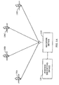
- FIG. 1A is a simplified illustration of a system capable of implementing various aspects of the invention.
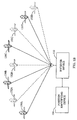
- FIG. 1B is a diagram that illustrates the error in the location of the transmitters based on information available to the receiver device.
- FIG. 2 is a simplified block diagram of the receiver device and the position identifying device in accordance an embodiment of the invention.
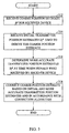
- FIG. 3 is a flow diagram illustrating a process performed by the position identifying device to derive a more accurate position estimate for the receiver device based on a coarse position estimate previously derived by the receiver device.
- FIG. 4 is a flow diagram of the processing performed for the iterative algorithm, in accordance with an embodiment of the invention.
- FIG. 1A is a simplified illustration of a system capable of implementing various aspects of the invention.
- a receiver device 110 receives signals transmitted from a plurality of the transmitters 130a-130d (referenced collectively using reference number "130") via an antenna.
- the receiver device 110 further communicates with a position identifying device 120, which assists in determining the position of the receiver device, as described in further detail below.
- the receiver device 110 is a cellular telephone capable of receiving signals from the plurality of the transmitters 130.
- the receiver device 110 may be any device capable of determining the arrival times of received signals with respect to a reference time.
- the receiver device 110 may be a computer terminal having a wireless modem, a stand-alone GPS receiver, a receiver capable of receiving signals from ground-based transmitters, or any other receiver.
- the transmitters 130 may be any type of transmitter having locations that are known or which can be ascertained.
- the transmitters 130 are satellites of a Global Positioning Satellite (GPS) system.
- GPS Global Positioning Satellite
- the transmitters 130 may be ground-based transmitters (e.g., base stations of a wireless communication system), or a combination of GPS and ground-based transmitters.
- the receiver device 110 estimates its position based on the received signals and information indicative of the location of the transmitters 130 from which the received signals were transmitted. Due to various factors, the receiver device 110 may not have current or accurate information regarding the actual location of the transmitters 130. In such case, the position estimate made by the receiver device 110 of its location is coarse and may not have the desired degree of accuracy. The initial coarse position estimate made using less accurate transmitter locations may thereafter be "corrected" to provide a more accurate position estimate of the receiver device using the techniques described herein.
- the transmitters 130 can be used as reference points to determine the location of the receiver device 110. By accurately measuring the distances from three transmitters 130, the receiver device 110 can "triangulate" its position. The receiver device 110 determines distance by measuring the time required for a signal to travel from a transmitter 130 to the receiver device 110. By knowing the time the signal is transmitted from the transmitter 130 and observing the time the signal is received by the receiver device 110 (based on its internal clock), the travel time of the signal can be determined. However, the exact amount of time between transmission and reception typically cannot be determined, for example, due to offsets in the two clocks at the transmitter 130 and the receiver device 110.
- a "pseudo-range” is typically computed based on the difference between a "reference” time and the time that the signal is received.
- the reference time may be any time, as long as the reference time is common to all pseudo-range measurements being made (or the pseudo-range measurements can be adjusted to compensate for differences in the reference times used).
- the transmitters 130a through 130d are shown at positions estimated by the receiver device 110 based on less accurate (e.g., not up-to-date) information. These positions may be different from the actual positions of the transmitters 130.
- the transmitters 130 are satellites, such as GPS satellites, the position of the satellites can be identified by the Almanac and Ephemeris.
- An accurate determination of the location of a GPS satellite can be made if the current Ephemeris information and the time of day are available. However, the Ephemeris information is valid for a limited amount of time (e.g., two hours). A less accurate determination of the GPS satellite location can be made if current Almanac information and the time of day are available. However, the Almanac is also valid for a limited amount of time (e.g., one week).
- aspects of the invention provide techniques to accurately determine the location of a receiver device based on an initial coarse position estimate, which may have been derived using less accurate information regarding the location of the transmitters (e.g., an old Almanac or old Ephemeris for the GPS satellites). It should be understood that the initial estimate may be made based upon completely outdated Almanac or Ephemeris information.
- corrections to the coarse position estimate of receiver device are made based on: (1) more accurate information regarding the location of the transmitters 130; and (2) information regarding the amount of error in the estimates of the location of the transmitters 130 used to derive the coarse position estimate. Techniques to perform the corrections are described in further detail below.
- the corrections are made at the position identifying device 120, which may be remotely located with respect to the receiver device 110. However, in other embodiments of the disclosed method and apparatus, the position identifying device 120 may be co-located with the receiver device 110.
- FIG. 2 is a simplified block diagram of the receiver device 110 and the position identifying device 120 in accordance with one embodiment of the disclosed method and apparatus.
- the receiver device 110 may be a component of a remote terminal in a wireless communication system, such as a cellular telephone or a computer with a wireless modem.
- the receiver device 110 may be a stand-alone position determining unit, such as a stand-alone GPS receiver.
- the position identifying device 120 may be a component of a base transceiver subsystem (BTS), a base station controller (BSC), or a mobile switching controller (MSC) in a wireless communication system, or may be a device that couples to one of these elements of the wireless communication system.
- the position identifying device 120 may be a Position Determining Equipment (PDE) in a wireless communication system.
- PDE Position Determining Equipment
- the position identifying device 120 may be a component of, and co-located with, a remote terminal or some other device that includes the receiver device 110.
- the position identifying device 120 may be a stand alone component.
- the receiver device 110 and the position identifying device 120 are shown in FIG. 2 as being directly coupled. However, one or more additional elements (e.g., a BTS, a BSC, and so on) may be coupled between the receiver device 110 and the position identifying device 120.
- the position identifying device 120 and the receiver device 110 may also be co-located. This may be the case in a system in which accurate information about the location of the transmitters 130 is not available when the measurements are made, but is available at some time in the future.
- a coarse position estimate for the receiver device 110 may be derived immediately upon making the pseudo-range (or actual range) measurements. The coarse position estimate may be stored until information regarding the more accurate location of the transmitters 130 becomes available, after which a more accurate position estimate for the receiver device may be derived.
- the receiver device 110 includes a receiver 210, a processing circuit 212, a memory 214, and a communications port 216, and further couples to an antenna 208.
- the antenna 208 receives signals from the transmitters 130 (shown in FIG. 1A ) and couples the received signals to the receiver 210.
- the receiver 210 includes circuitry (e.g., radio frequency (RF) processing circuitry and/or other receiving circuitry) necessary to process the received signals to derive information used for position determination. Such information may include timing information and so on.
- the information is provided to the processing circuit 212, which performs position determining calculations. Such calculations may include calculations to derive pseudo-ranges to the transmitters 130. Alternatively or additionally, the calculations may include those required to derive an initial coarse estimate of the position of the receiver device 110. The coarse position estimate may have a relatively large error due to large errors in the position estimates of the transmitters 130.
- the receiver device 110 provides the results of the calculations and other pertinent information via a communication port 216 to the position identifying device 120.
- the pertinent information may include the time the received signals were measured, the information used to perform the calculations (e.g., the particular Almanac used to estimate the position of the transmitters 130), and possibly other information.
- the communication port 216 provides an interface to the position identifying device 120.
- the communication port 216 may support communication via a wireless link.
- the position identifying device 120 includes a communication port 220, a processing circuit 222, and a memory 224.
- the communication port 220 receives the calculation results and pertinent information from the receiver device 110 and forwards the information to the processing circuit 222.
- the processing circuit 222 receives the calculation results and pertinent information, and further receives a copy of the "less accurate" information that was used by the receiver device 110 to perform the calculations.
- the less accurate information may be the Almanac (and the time at which the Almanac was valid), the Ephemeris (and the time at which the Ephemeris was valid), and/or any other information that the receiver device 110 may have used to estimate the location of the transmitters 130.
- the less accurate information may be provided by the receiver device 110 together with the calculation results, e.g., as part of the pertinent information.
- the less accurate information may not be explicitly provided, and other indicators may be used to deduce the information that was used.
- the time for which the Almanac or Ephemeris is valid, the time at which the received signals were measured at the receiver device 110, the time at which the coarse position estimate was sent to the position identifying device 120, or some other information (which may be sent as part of the pertinent information) may be sufficient to allow the position identifying device 120 to correctly deduce the transmitter position estimates that were used to derive the coarse position estimate.
- the position identifying device 120 may be responsible for sending to the receiver device 110 the information used to derive the coarse position estimate. For these embodiments, there would be no need for the receiver device 110 to inform the position identifying device 120 what information was used.
- the processing circuit 212 may communicate directly with the position identifying device 120 without the need for a separate communication port. This may be the case in instances in which the position identifying device 120 and the receiver device 110 are co-located, or may even be possible in certain other instances in which the position identifying device and receiver device are not co-located.
- the position identifying device 120 receives the less accurate information prior to receipt of the calculation results from the receiver device 110.
- the less accurate information used by the receiver device 110 may be provided to the position identifying device 120 by a source other than the receiver device 110 (e.g., over a communication link that is not shown in FIG. 2 for simplicity).
- the less accurate information may be received directly by the position identifying device 120 from the transmitters 130.
- the less accurate information may be received by the position identifying device 120 from a source that is distinct from any of the components shown in FIG. 1A , such as a component of a base station in a wireless communication system.
- the position identifying device 120 may have multiple sets of information (e.g., several versions of the Almanac), any one of which may have been used by the receiver device 110 to perform the position determining calculations.
- the receiver device 110 may need to provide additional information to the position identifying device 120 to indicate what information, from among those available to the position identifying device 120, was specifically used by the receiver device 110 to perform the position determining calculation.
- FIG. 3 is a flow diagram illustrating a process performed by the position identifying device 120 to derive a more accurate position estimate for the receiver device 110 based on a coarse position estimate previously derived by the receiver device.
- the position identifying device 120 initially receives from the receiver device 110 the results of the position determination calculations (e.g., the coarse position estimate u a ), at step 312.
- the position identifying device 120 also receives information indicative of the initial position estimates s ⁇ i a of the transmitters 130 (i.e., the less accurate transmitter position estimates), which were used to derive the coarse position estimate, at step 314.
- This information may indicate the version of the Almanac or Ephemeris that was used to derive the coarse position estimate.
- the initial position estimates for the transmitters 130, as determined by the receiver device 110, are less accurate and correspond to the location where the receiver device 110 assumed the transmitters to be located when making the position determining calculations.
- the position identifying device 120 further receives the time at which the pseudo-range measurements were taken, also at step 314.
- the position identifying device 120 determines more accurate estimates s ⁇ i e of the location of the transmitters 130, at step 316. These more accurate transmitter position estimates may be made based on an Almanac and/or Ephemeris that is more accurate for the time at which the pseudo-range measurements were made by the receiver device 110. In one embodiment, the position identifying device 120 maintains a log of the Almanac and Ephemeris transmitted by the satellites of the GPS constellation. Such a log allows the position identifying device 120 to use the most accurate Almanac and Ephemeris to correct the coarse position estimate received from the receiver device 110, as described in further detail below.
- the position identifying device 120 corrects the coarse position estimate for the receiver device 110 in accordance with an algorithm described below, at step 318.
- FIG. 1B is a diagram that illustrates the error in the location of the transmitters 130 based on information available to the receiver device 110.
- FIG. 1B shows transmitters 132a through 132d at locations that represent the more accurate estimates of the actual location of the transmitters.
- FIG. 1B also shows the transmitters 130a through 130d at locations that represent less accurate estimates of the location of the transmitters.
- Transmitter 132 shown with dashed lines
- the transmitter 130 shown with solid lines
- the locations of the transmitters 130 were used by the receiver device 110 to perform the position determining calculations to derive the coarse position estimate for the receiver device 110.
- the position identifying device 120 performs corrections on the coarse position estimate from the receiver device 110 to provide a more accurate position estimate for the receiver device.
- the corrections on the coarse position estimate may be performed based on various algorithms including a "linearized” algorithm, an “iterative algorithm”, and possibly others.
- the linearized algorithm is described in detail in U.S Patent Application Serial No. 09/773,207 , entitled “METHOD AND APPARATUS FOR DETERMINING LOCATION USING A COARSE POSITION ESTIMATE,” filed January 30, 2001, assigned to the assignee of the present application.
- the iterative algorithm is described below.
- the iterative algorithm can be used to perform corrections on a coarse position estimate for the receiver device 110 based on: (1) knowledge of the less accurate estimates of the location of the transmitters 130 (e.g., GPS satellites) used to derive the coarse position estimate for the receiver device 110, and (2) a knowledge of the more accurate estimates of the actual location of the transmitters 130 at the time the pseudo-range measurements were made.
- the more accurate transmitter position estimates may be determined based on knowledge of the specific time at which the pseudo-range measurements were taken.
- the coarse position estimate is made at either a location or a time when the more accurate estimates of the location of the transmitters 130 are not available. Corrections will typically be performed at either a later time or another location or both, depending upon when and where the more accurate estimates of the position of the transmitters 130 become available.
- the iterative algorithm is described specifically for a case in which the transmitters 130 are GPS satellites. However, the iterative algorithm may also be used with any types of transmitter in which inaccurate transmitter location information is available at a particular time or place, and more accurate transmitter location information is available at some later time and/or other location.
- Clock bias is defined as the difference between the time indicated by the local clock in the receiver device 110 and the time indicated by the clock in the transmitter 130.
- the location, s ⁇ i a will typically have a relatively large error due to inaccuracy of the Almanac used by the receiver device 110 to derive the location, s ⁇ i a .
- the location, s ⁇ i e will typically have a relatively small error due to the use of the more accurate Ephemeris information.
- the value of the more accurate position estimate u e may be set to u n .
- the position estimate u e is thereafter updated as more information is obtained.
- These range estimates are essentially pseudo-range measurements that would have been determined by a receiving device located at u e receiving signals from transmitters located at the locations indicated by the more accurate information. It can be seen that the measurement, m i of equation (1) is the distance between the more accurate position estimate u e of the receiver device 110 and the more accurate position estimate s ⁇ i e of one of the transmitters 132, taking into account the clock bias.
- LMS least mean square
- FIG. 4 is a flow diagram of the processing performed for the iterative algorithm, in accordance with an embodiment of the invention.
- the coarse position estimate u a derived by the receiver device 110 based on less accurate position estimates s ⁇ i a of the transmitters 130 is first received (as described in FIG. 3 ).
- the more accurate position estimate u e for the receiver device 110 is initialized to the coarse position estimate u a , at step 412.
- Pseudo-range measurements m i are then determined, at step 414. These measurements are the ones that would have been obtained if the position estimate u e were the solution.
- the measurements m i can be derived based on equation (1) and can be determined for all transmitters previously used to derive the coarse position estimate u a .
- an LMS computation is performed based on the measurements m i determined in step 414 and the less accurate transmitter position estimates s ⁇ i a .
- the LMS computation can be achieved in a manner known in the art.
- the resulting solution from the LMS computation is denoted as u ' , which is the solution that the receiver device 110 would have obtained if it had been at location u e .
- the geometry matrix H is then computed in accordance with equations (2), (3) and (4), at step 418.
- the update vector d u can then be determined based on the geometry matrix H t and the difference in position estimates (i.e., u a - u ' ) and in accordance with equation (5), at step 420.
- the more accurate position estimate u e is then updated with the update vector d u , at step 422.
- a particular threshold e.g.,
- the techniques described herein allow the location of a receiver device to be accurately determined based on a coarse location estimate for the receiver device, which may have been derived based on less accurate position estimates for the transmitters.
- the information descriptive of the location of the transmitters e.g., the Almanac
- the receiver device may be accurately determined based on a coarse location estimate for the receiver device, which may have been derived based on less accurate position estimates for the transmitters.
- the information descriptive of the location of the transmitters e.g., the Almanac
- the receiver device may be accurately determined based on a coarse location estimate for the receiver device, which may have been derived based on less accurate position estimates for the transmitters.
- the information descriptive of the location of the transmitters e.g., the Almanac
- the techniques described herein may also be used advantageously for determining the position of a receiver device operating in an analog mode, which is characterized by the time stamp of the measurements not being known with sufficient accuracy (e.g., more than 5 msec of time stamp error).
- measurements for five or more transmitters may be used to solve for x, y, z, and clock bias as well as the time-stamp error.
- the correction algorithm described above can be made applicable for cases where the time-stamp reported by the receiver device is not accurate.
- the iterative algorithm described above can be implemented for position determining calculations based on five or more measurements.
- the computations described above in equations (1) through (6) and the flow diagram shown in FIG. 4 can be applied in the manner described above.
- a modified LMS algorithm is implemented to operate on five unknowns to derive the solution (i.e., the position estimate for the receiver device).
- these matrices would have a dimensionality corresponding to the number of measurements used.
- H a , 5 x u ⁇ - x S ⁇ 1 a u ⁇ ⁇ ⁇ - s ⁇ 1 a y u ⁇ - y S ⁇ 1 a u ⁇ ⁇ ⁇ - s ⁇ 1 a z u ⁇ - z S ⁇ 1 a u ⁇ ⁇ ⁇ - s ⁇ 1 a - 1 ⁇ ⁇ S ⁇ 1 a ⁇ t x u ⁇ - x S ⁇ 2 a u ⁇ ⁇ ⁇ - s ⁇ 2 a y u ⁇ - y S ⁇ 2 a u ⁇ ⁇ - s ⁇ 2 a z u ⁇ - z S ⁇ 2 a u ⁇ ⁇ - s ⁇ 2 a - 1
- the first four columns of the above matrix H a , 5 are the same as that shown above in equation (2) and the fifth column comprises the partial derivative ⁇ ⁇ Si a ⁇ t of each transmitter's pseudo-range measurement with respect to the time-stamp.
- t t k ⁇ x Si a t k - x u a + ⁇ y Si a ⁇ t
- t t k ⁇ y Si a t k - y u a + ⁇ z Si a ⁇ t
- t t k ⁇ z Si a t k - z u a x Si a t k - x u a 2 + y Si a t k - y u a 2 + z Si a t k
- H e , 5 x u e - x S ⁇ 1 e u ⁇ e - s ⁇ 1 e y u e - y S ⁇ 1 e u ⁇ e - s ⁇ 1 e z u e - z S ⁇ 1 e u ⁇ e - s ⁇ 1 e - 1 ⁇ ⁇ S ⁇ 1 e ⁇ t x u e - x S ⁇ 2 e u ⁇ e - s ⁇ 2 e y u e - y S ⁇ 2 e u ⁇ e - s ⁇ 2 e z u e - z S ⁇ 2 e u ⁇ e - s ⁇ 2 e - 1 ⁇ ⁇ S ⁇ 1 e ⁇ t M M M M M M M M M M M M M M M M M M M M M M M M M M M M
- the first four columns of the above matrix H e,5 are the same as that shown above in equation (3) and the fifth column comprises the partial derivative ⁇ ⁇ Si e ⁇ t of each transmitter's pseudo-range measurement with respect to the time-stamp.
- t t k ⁇ x Si e t k - x u e + ⁇ y Si e ⁇ t
- t t k ⁇ y Si e t k - y u e + ⁇ z Si e ⁇ t
- t t k ⁇ z Si e t k - z u e x Si e t k - x u e 2 + y Si e t k - y u e 2 + z Si e t k
- the partial derivatives (e.g., ⁇ x Si a ⁇ t , ⁇ y Si a ⁇ t , and ⁇ y Si a ⁇ t ) of each satellite's coordinate with respect to the measurement time can be derived from the Almanac or Ephemeris accordingly, since they described the satellite's trajectory as a function of time.
- t k is the estimate of the measurement time at the k th iteration. From the above equations, at each iteration, the satellite positions are recomputed based on the new value of the measurement time t, which may be obtained from the measurement time error that is one of the unknowns whose value is reassessed at each iteration.
- processing circuits 212 and 222 may derive the initial coarse position estimate and the more accurate position estimate for the receiver device 110, respectively, by executing program instructions stored within memories 214 and 224, respectively.
- Processing circuits 212 and 214 may each be implemented as a digital signal processor (DSP), an application specific integrated circuit (ASIC), a processor, a microprocessor, a controller, a microcontroller, a field programmable gate array (FPGA), a programmable logic device, other electronic unit, or any combination thereof designed to perform the functions described herein.
- Processing circuits 212 and 222 may each further include memory 212 or 224 used to store program instructions and data.
Landscapes
- Engineering & Computer Science (AREA)
- Radar, Positioning & Navigation (AREA)
- Remote Sensing (AREA)
- Computer Networks & Wireless Communication (AREA)
- Physics & Mathematics (AREA)
- General Physics & Mathematics (AREA)
- Computer Security & Cryptography (AREA)
- Position Fixing By Use Of Radio Waves (AREA)
- Radar Systems Or Details Thereof (AREA)
Applications Claiming Priority (3)
| Application Number | Priority Date | Filing Date | Title |
|---|---|---|---|
| US27357001P | 2001-03-05 | 2001-03-05 | |
| US09/878,934 US6570530B2 (en) | 2001-03-05 | 2001-06-11 | Method and apparatus providing improved position estimate based on an initial coarse position estimate |
| EP02704464A EP1366376B1 (en) | 2001-03-05 | 2002-03-01 | Method and apparatus providing improved position estimate based on an initial coarse position estimate |
Related Parent Applications (1)
| Application Number | Title | Priority Date | Filing Date |
|---|---|---|---|
| EP02704464.3 Division | 2002-03-01 |
Publications (2)
| Publication Number | Publication Date |
|---|---|
| EP2259087A1 EP2259087A1 (en) | 2010-12-08 |
| EP2259087B1 true EP2259087B1 (en) | 2012-02-29 |
Family
ID=26956300
Family Applications (2)
| Application Number | Title | Priority Date | Filing Date |
|---|---|---|---|
| EP10178890A Expired - Lifetime EP2259087B1 (en) | 2001-03-05 | 2002-03-01 | Method and apparatus providing improved position estimate based on an initial coarse position estimate |
| EP02704464A Expired - Lifetime EP1366376B1 (en) | 2001-03-05 | 2002-03-01 | Method and apparatus providing improved position estimate based on an initial coarse position estimate |
Family Applications After (1)
| Application Number | Title | Priority Date | Filing Date |
|---|---|---|---|
| EP02704464A Expired - Lifetime EP1366376B1 (en) | 2001-03-05 | 2002-03-01 | Method and apparatus providing improved position estimate based on an initial coarse position estimate |
Country Status (11)
| Country | Link |
|---|---|
| US (1) | US6570530B2 (enExample) |
| EP (2) | EP2259087B1 (enExample) |
| JP (1) | JP4119256B2 (enExample) |
| KR (2) | KR100941342B1 (enExample) |
| CN (2) | CN101311745B (enExample) |
| AT (2) | ATE547724T1 (enExample) |
| BR (1) | BR0207903A (enExample) |
| CA (1) | CA2439880C (enExample) |
| IL (3) | IL157438A0 (enExample) |
| MX (1) | MXPA03008016A (enExample) |
| WO (1) | WO2002071095A2 (enExample) |
Families Citing this family (120)
| Publication number | Priority date | Publication date | Assignee | Title |
|---|---|---|---|---|
| US10361802B1 (en) | 1999-02-01 | 2019-07-23 | Blanding Hovenweep, Llc | Adaptive pattern recognition based control system and method |
| US8352400B2 (en) | 1991-12-23 | 2013-01-08 | Hoffberg Steven M | Adaptive pattern recognition based controller apparatus and method and human-factored interface therefore |
| US7966078B2 (en) | 1999-02-01 | 2011-06-21 | Steven Hoffberg | Network media appliance system and method |
| US7018401B1 (en) * | 1999-02-01 | 2006-03-28 | Board Of Regents, The University Of Texas System | Woven intravascular devices and methods for making the same and apparatus for delivery of the same |
| US7949362B2 (en) * | 2000-05-18 | 2011-05-24 | Sirf Technology, Inc. | Satellite positioning aided communication system selection |
| US8078189B2 (en) * | 2000-08-14 | 2011-12-13 | Sirf Technology, Inc. | System and method for providing location based services over a network |
| US8116976B2 (en) | 2000-05-18 | 2012-02-14 | Csr Technology Inc. | Satellite based positioning method and system for coarse location positioning |
| US7263440B2 (en) * | 2000-05-18 | 2007-08-28 | Sirf Technology, Inc. | Satellite based positioning method and system for coarse location positioning |
| US7970411B2 (en) | 2000-05-18 | 2011-06-28 | Sirf Technology, Inc. | Aided location communication system |
| US7929928B2 (en) * | 2000-05-18 | 2011-04-19 | Sirf Technology Inc. | Frequency phase correction system |
| US20070200752A1 (en) * | 2001-06-06 | 2007-08-30 | Global Locate, Inc. | Method and apparatus for maintaining integrity of long-term orbits in a remote receiver |
| WO2002073937A2 (en) * | 2001-03-14 | 2002-09-19 | Mercury Computer Systems, Inc. | Wireless communications methods and systems for long-code and other spread spectrum waveform processing |
| US8212719B2 (en) * | 2001-06-06 | 2012-07-03 | Global Locate, Inc. | Method and apparatus for background decoding of a satellite navigation message to maintain integrity of long term orbit information in a remote receiver |
| US6651000B2 (en) | 2001-07-25 | 2003-11-18 | Global Locate, Inc. | Method and apparatus for generating and distributing satellite tracking information in a compact format |
| US6708116B2 (en) * | 2001-11-13 | 2004-03-16 | Analytical Graphics, Inc. | Method and apparatus for orbit determination |
| US7321775B2 (en) * | 2001-11-28 | 2008-01-22 | Nokia Corporation | Method for obtaining location related information allowing to locate a terminal attached to a communication network |
| US7426380B2 (en) | 2002-03-28 | 2008-09-16 | Telecommunication Systems, Inc. | Location derived presence information |
| US8290505B2 (en) | 2006-08-29 | 2012-10-16 | Telecommunications Systems, Inc. | Consequential location derived information |
| US8918073B2 (en) | 2002-03-28 | 2014-12-23 | Telecommunication Systems, Inc. | Wireless telecommunications location based services scheme selection |
| US8027697B2 (en) | 2007-09-28 | 2011-09-27 | Telecommunication Systems, Inc. | Public safety access point (PSAP) selection for E911 wireless callers in a GSM type system |
| US9154906B2 (en) | 2002-03-28 | 2015-10-06 | Telecommunication Systems, Inc. | Area watcher for wireless network |
| US8126889B2 (en) | 2002-03-28 | 2012-02-28 | Telecommunication Systems, Inc. | Location fidelity adjustment based on mobile subscriber privacy profile |
| US7239271B1 (en) * | 2002-08-15 | 2007-07-03 | Sirf Technology, Inc. | Partial almanac collection system |
| JP4255441B2 (ja) | 2002-08-15 | 2009-04-15 | サーフ テクノロジー インコーポレイテッド | Gpsシステム用インターフェース |
| US7660588B2 (en) * | 2002-10-17 | 2010-02-09 | Qualcomm Incorporated | Method and apparatus for improving radio location accuracy with measurements |
| US8666397B2 (en) | 2002-12-13 | 2014-03-04 | Telecommunication Systems, Inc. | Area event handling when current network does not cover target area |
| KR100498480B1 (ko) | 2003-01-23 | 2005-07-01 | 삼성전자주식회사 | Gps 위성 신호를 이용한 위치추정방법 및 위치추정장치 |
| US7375654B2 (en) * | 2003-08-01 | 2008-05-20 | Spectrum Tracking Systems, Inc. | Method and system for providing tracking services to locate an asset |
| US7424293B2 (en) | 2003-12-02 | 2008-09-09 | Telecommunication Systems, Inc. | User plane location based service using message tunneling to support roaming |
| US7260186B2 (en) | 2004-03-23 | 2007-08-21 | Telecommunication Systems, Inc. | Solutions for voice over internet protocol (VoIP) 911 location services |
| US20080126535A1 (en) | 2006-11-28 | 2008-05-29 | Yinjun Zhu | User plane location services over session initiation protocol (SIP) |
| US20080090546A1 (en) | 2006-10-17 | 2008-04-17 | Richard Dickinson | Enhanced E911 network access for a call center using session initiation protocol (SIP) messaging |
| JP4315832B2 (ja) * | 2004-02-17 | 2009-08-19 | 三菱電機株式会社 | 熱型赤外センサ素子および熱型赤外センサアレイ |
| US7113128B1 (en) | 2004-10-15 | 2006-09-26 | Telecommunication Systems, Inc. | Culled satellite ephemeris information for quick, accurate assisted locating satellite location determination for cell site antennas |
| US7629926B2 (en) | 2004-10-15 | 2009-12-08 | Telecommunication Systems, Inc. | Culled satellite ephemeris information for quick, accurate assisted locating satellite location determination for cell site antennas |
| US6985105B1 (en) | 2004-10-15 | 2006-01-10 | Telecommunication Systems, Inc. | Culled satellite ephemeris information based on limiting a span of an inverted cone for locating satellite in-range determinations |
| US7411546B2 (en) | 2004-10-15 | 2008-08-12 | Telecommunication Systems, Inc. | Other cell sites used as reference point to cull satellite ephemeris information for quick, accurate assisted locating satellite location determination |
| US8369264B2 (en) | 2005-10-28 | 2013-02-05 | Skyhook Wireless, Inc. | Method and system for selecting and providing a relevant subset of Wi-Fi location information to a mobile client device so the client device may estimate its position with efficient utilization of resources |
| US7493127B2 (en) | 2005-02-22 | 2009-02-17 | Skyhook Wireless, Inc. | Continuous data optimization of new access points in positioning systems |
| US7353034B2 (en) | 2005-04-04 | 2008-04-01 | X One, Inc. | Location sharing and tracking using mobile phones or other wireless devices |
| JP4813190B2 (ja) * | 2005-05-26 | 2011-11-09 | オリンパスメディカルシステムズ株式会社 | カプセル型医療装置 |
| US7079075B1 (en) * | 2005-06-07 | 2006-07-18 | Trimble Navigation Limited | GPS rover station for synthesizing synthetic reference phases for controlling accuracy of high integrity positions |
| RU2292060C1 (ru) * | 2005-06-28 | 2007-01-20 | Рязанская государственная радиотехническая академия | Способ наблюдения за воздушными объектами и поверхностью на базе бортовой рлс |
| US8660573B2 (en) | 2005-07-19 | 2014-02-25 | Telecommunications Systems, Inc. | Location service requests throttling |
| US9282451B2 (en) | 2005-09-26 | 2016-03-08 | Telecommunication Systems, Inc. | Automatic location identification (ALI) service requests steering, connection sharing and protocol translation |
| US7825780B2 (en) | 2005-10-05 | 2010-11-02 | Telecommunication Systems, Inc. | Cellular augmented vehicle alarm notification together with location services for position of an alarming vehicle |
| US8467320B2 (en) | 2005-10-06 | 2013-06-18 | Telecommunication Systems, Inc. | Voice over internet protocol (VoIP) multi-user conferencing |
| US7907551B2 (en) | 2005-10-06 | 2011-03-15 | Telecommunication Systems, Inc. | Voice over internet protocol (VoIP) location based 911 conferencing |
| US7626951B2 (en) | 2005-10-06 | 2009-12-01 | Telecommunication Systems, Inc. | Voice Over Internet Protocol (VoIP) location based conferencing |
| US8150363B2 (en) | 2006-02-16 | 2012-04-03 | Telecommunication Systems, Inc. | Enhanced E911 network access for call centers |
| WO2007101107A2 (en) * | 2006-02-24 | 2007-09-07 | Skyhook Wireless, Inc. | Methods and systems for estimating a user position in a wlan positioning system based on user assigned access point locations |
| US8059789B2 (en) | 2006-02-24 | 2011-11-15 | Telecommunication Systems, Inc. | Automatic location identification (ALI) emergency services pseudo key (ESPK) |
| US7899450B2 (en) | 2006-03-01 | 2011-03-01 | Telecommunication Systems, Inc. | Cellular augmented radar/laser detection using local mobile network within cellular network |
| US9167553B2 (en) | 2006-03-01 | 2015-10-20 | Telecommunication Systems, Inc. | GeoNexus proximity detector network |
| US7471236B1 (en) | 2006-03-01 | 2008-12-30 | Telecommunication Systems, Inc. | Cellular augmented radar/laser detector |
| RU2413959C2 (ru) * | 2006-03-06 | 2011-03-10 | Квэлкомм Инкорпорейтед | Способ определения положения путем сшивания измерений |
| US8208605B2 (en) | 2006-05-04 | 2012-06-26 | Telecommunication Systems, Inc. | Extended efficient usage of emergency services keys |
| CA2657207A1 (en) | 2006-07-07 | 2008-01-10 | Skyhook Wireless, Inc. | Systems and methods of gathering information from wlan-enabled access points to estimate position of a wlan positioning device |
| US20080068262A1 (en) * | 2006-08-25 | 2008-03-20 | Peter Van Wyck Loomis | Remote node providing GPS signal samples for GPS positioning over a communication network |
| US7589671B2 (en) * | 2006-08-25 | 2009-09-15 | Trimble Navigation Limited | GPS node locator using an intermediate node location for determining location of a remote node |
| WO2008057477A2 (en) | 2006-11-03 | 2008-05-15 | Telecommunication Systems, Inc. | Roaming gateway enabling location based services (lbs) roaming for user plane in cdma networks without requiring use of a mobile positioning center (mpc) |
| US7439907B2 (en) * | 2006-11-20 | 2008-10-21 | Sirf Technology Holdihgs, Inc. | Navigation signal receiver trajectory determination |
| US7436357B2 (en) * | 2006-11-20 | 2008-10-14 | Centrality Communications, Inc. | Background ephemeris download in navigational receivers |
| CA2597347A1 (en) * | 2006-11-30 | 2008-05-30 | Ittay Ronen | Automated travel log system |
| US8050386B2 (en) | 2007-02-12 | 2011-11-01 | Telecommunication Systems, Inc. | Mobile automatic location identification (ALI) for first responders |
| US7551126B2 (en) * | 2007-03-08 | 2009-06-23 | Trimble Navigation Limited | GNSS sample processor for determining the location of an event |
| US7719467B2 (en) * | 2007-03-08 | 2010-05-18 | Trimble Navigation Limited | Digital camera with GNSS picture location determination |
| WO2009038726A1 (en) | 2007-09-17 | 2009-03-26 | Telecommunication Systems, Inc. | Emergency 911 data messaging |
| US9130963B2 (en) | 2011-04-06 | 2015-09-08 | Telecommunication Systems, Inc. | Ancillary data support in session initiation protocol (SIP) messaging |
| US7929530B2 (en) | 2007-11-30 | 2011-04-19 | Telecommunication Systems, Inc. | Ancillary data support in session initiation protocol (SIP) messaging |
| US8068587B2 (en) | 2008-08-22 | 2011-11-29 | Telecommunication Systems, Inc. | Nationwide table routing of voice over internet protocol (VOIP) emergency calls |
| US8614975B2 (en) | 2008-09-19 | 2013-12-24 | Qualcomm Incorporated | Synchronizing a base station in a wireless communication system |
| US8892128B2 (en) | 2008-10-14 | 2014-11-18 | Telecommunication Systems, Inc. | Location based geo-reminders |
| WO2010044837A1 (en) | 2008-10-14 | 2010-04-22 | Telecommunication Systems, Inc. | Location based proximity alert |
| US9037155B2 (en) | 2008-10-28 | 2015-05-19 | Sven Fischer | Time of arrival (TOA) estimation for positioning in a wireless communication network |
| US8982851B2 (en) | 2009-01-06 | 2015-03-17 | Qualcomm Incorporated | Hearability improvements for reference signals |
| US9301191B2 (en) | 2013-09-20 | 2016-03-29 | Telecommunication Systems, Inc. | Quality of service to over the top applications used with VPN |
| US8867485B2 (en) | 2009-05-05 | 2014-10-21 | Telecommunication Systems, Inc. | Multiple location retrieval function (LRF) network having location continuity |
| US9074897B2 (en) | 2009-06-15 | 2015-07-07 | Qualcomm Incorporated | Real-time data with post-processing |
| US8688139B2 (en) * | 2009-09-10 | 2014-04-01 | Qualcomm Incorporated | Concurrent wireless transmitter mapping and mobile station positioning |
| CN102783227B (zh) * | 2010-02-19 | 2018-03-16 | 无线星球有限责任公司 | 确定定时不确定性的方法和装置 |
| WO2011100859A1 (en) | 2010-02-19 | 2011-08-25 | Telefonaktiebolaget L M Ericsson (Publ) | Improvements on otdoa and agnss positioning and timing information obtaining and updating |
| US9253605B2 (en) | 2010-03-24 | 2016-02-02 | Skyhook Wireless, Inc. | System and method for resolving multiple location estimate conflicts in a WLAN-positioning system |
| US8704707B2 (en) | 2010-06-02 | 2014-04-22 | Qualcomm Incorporated | Position determination using measurements from past and present epochs |
| US8700053B2 (en) | 2010-06-11 | 2014-04-15 | Skyhook Wireless, Inc. | Systems for and methods of determining likelihood of relocation of reference points in a positioning system |
| US9091746B2 (en) | 2010-07-01 | 2015-07-28 | Qualcomm Incorporated | Determination of positions of wireless transceivers to be added to a wireless communication network |
| WO2012005769A1 (en) | 2010-07-09 | 2012-01-12 | Telecommunication Systems, Inc. | Location privacy selector |
| US20120006610A1 (en) | 2010-07-09 | 2012-01-12 | Erik Wallace | Telematics enhanced mobile device safety interlock |
| WO2012028903A1 (en) * | 2010-09-01 | 2012-03-08 | Nokia Corporation | Localization based on individual location patterns |
| US8606294B2 (en) | 2010-10-05 | 2013-12-10 | Skyhook Wireless, Inc. | Method of and system for estimating temporal demographics of mobile users |
| US8688087B2 (en) | 2010-12-17 | 2014-04-01 | Telecommunication Systems, Inc. | N-dimensional affinity confluencer |
| US8942743B2 (en) | 2010-12-17 | 2015-01-27 | Telecommunication Systems, Inc. | iALERT enhanced alert manager |
| US8825813B2 (en) | 2010-12-28 | 2014-09-02 | Microsoft Corporation | Distributed network coordinate system based on network performance |
| US8682321B2 (en) | 2011-02-25 | 2014-03-25 | Telecommunication Systems, Inc. | Mobile internet protocol (IP) location |
| US20120331561A1 (en) | 2011-06-22 | 2012-12-27 | Broadstone Andrew J | Method of and Systems for Privacy Preserving Mobile Demographic Measurement of Individuals, Groups and Locations Over Time and Space |
| US8649806B2 (en) | 2011-09-02 | 2014-02-11 | Telecommunication Systems, Inc. | Aggregate location dynometer (ALD) |
| US9479344B2 (en) | 2011-09-16 | 2016-10-25 | Telecommunication Systems, Inc. | Anonymous voice conversation |
| WO2013048551A1 (en) | 2011-09-30 | 2013-04-04 | Telecommunication Systems, Inc. | Unique global identifier for minimizing prank 911 calls |
| US20130187810A1 (en) * | 2011-10-28 | 2013-07-25 | Maxime Leclercq | Method And System For An Embedded And Hosted Architecture For A Medium Earth Orbit Satellite And Low Earth Orbit Satellite Positioning Engine |
| US9313637B2 (en) | 2011-12-05 | 2016-04-12 | Telecommunication Systems, Inc. | Wireless emergency caller profile data delivery over a legacy interface |
| US9264537B2 (en) | 2011-12-05 | 2016-02-16 | Telecommunication Systems, Inc. | Special emergency call treatment based on the caller |
| US8984591B2 (en) | 2011-12-16 | 2015-03-17 | Telecommunications Systems, Inc. | Authentication via motion of wireless device movement |
| US9384339B2 (en) | 2012-01-13 | 2016-07-05 | Telecommunication Systems, Inc. | Authenticating cloud computing enabling secure services |
| US8688174B2 (en) | 2012-03-13 | 2014-04-01 | Telecommunication Systems, Inc. | Integrated, detachable ear bud device for a wireless phone |
| US9307372B2 (en) | 2012-03-26 | 2016-04-05 | Telecommunication Systems, Inc. | No responders online |
| US9544260B2 (en) | 2012-03-26 | 2017-01-10 | Telecommunication Systems, Inc. | Rapid assignment dynamic ownership queue |
| WO2013147560A1 (ko) * | 2012-03-30 | 2013-10-03 | Song Ha Yoon | 위치정보 보정방법 |
| KR101467317B1 (ko) * | 2012-03-30 | 2014-12-01 | 홍익대학교 산학협력단 | 위치 데이터의 오류여부 결정방법 |
| US9338153B2 (en) | 2012-04-11 | 2016-05-10 | Telecommunication Systems, Inc. | Secure distribution of non-privileged authentication credentials |
| WO2014028712A1 (en) | 2012-08-15 | 2014-02-20 | Telecommunication Systems, Inc. | Device independent caller data access for emergency calls |
| US9208346B2 (en) | 2012-09-05 | 2015-12-08 | Telecommunication Systems, Inc. | Persona-notitia intellection codifier |
| US9456301B2 (en) | 2012-12-11 | 2016-09-27 | Telecommunication Systems, Inc. | Efficient prisoner tracking |
| US8983047B2 (en) | 2013-03-20 | 2015-03-17 | Telecommunication Systems, Inc. | Index of suspicion determination for communications request |
| KR101467318B1 (ko) * | 2013-06-24 | 2014-12-02 | 홍익대학교 산학협력단 | 위치정보 보정방법 |
| US9408034B2 (en) | 2013-09-09 | 2016-08-02 | Telecommunication Systems, Inc. | Extended area event for network based proximity discovery |
| US9516104B2 (en) | 2013-09-11 | 2016-12-06 | Telecommunication Systems, Inc. | Intelligent load balancer enhanced routing |
| US9479897B2 (en) | 2013-10-03 | 2016-10-25 | Telecommunication Systems, Inc. | SUPL-WiFi access point controller location based services for WiFi enabled mobile devices |
| US11163070B2 (en) | 2016-04-22 | 2021-11-02 | Victoria Link Limited | Method and system for monitoring land deformation |
| JP6820781B2 (ja) * | 2017-03-28 | 2021-01-27 | 日鉄ソリューションズ株式会社 | システム、情報処理装置、情報処理方法及びプログラム |
| CN110087305B (zh) * | 2018-11-16 | 2021-06-04 | 上海二三四五网络科技有限公司 | 一种在应用程序中快速获取精确地理位置的控制方法及控制装置 |
Family Cites Families (13)
| Publication number | Priority date | Publication date | Assignee | Title |
|---|---|---|---|---|
| CN1063935A (zh) * | 1991-02-04 | 1992-08-26 | 中国人民解放军海军大连舰艇学院 | 舰船综合导航实用复合型自适应卡尔曼滤波器 |
| FR2696851B1 (fr) * | 1992-10-08 | 1994-11-04 | Alcatel Espace | Procédé de calcul de la position d'un mobile par un récepteur GPS. |
| US5444450A (en) * | 1993-08-11 | 1995-08-22 | Motorola, Inc. | Radio telecommunications system and method with adaptive location determination convergence |
| US6014101A (en) * | 1996-02-26 | 2000-01-11 | Trimble Navigation Limited | Post-processing of inverse DGPS corrections |
| JP2861957B2 (ja) * | 1996-07-31 | 1999-02-24 | トヨタ自動車株式会社 | 測位システム及びこのシステムに用いられる固定局側装置及び測位装置 |
| CN2277094Y (zh) * | 1996-12-27 | 1998-03-25 | 唐世明 | 组合导航惯性平台 |
| US5825328A (en) | 1997-01-11 | 1998-10-20 | Trimble Navigation Limited | Precise inverse differential corrections for location determination |
| US6084544A (en) * | 1997-12-18 | 2000-07-04 | Ericsson Inc. | Method for determining the location of a GPS receiver using an estimated reference time |
| US6104978A (en) * | 1998-04-06 | 2000-08-15 | General Electric Company | GPS-based centralized tracking system with reduced energy consumption |
| US6246363B1 (en) * | 1998-12-10 | 2001-06-12 | Hughes Electronics Corporation | Method and system for incorporating two-way ranging navigation as a calibration reference for GPS |
| US6453237B1 (en) | 1999-04-23 | 2002-09-17 | Global Locate, Inc. | Method and apparatus for locating and providing services to mobile devices |
| US6225945B1 (en) * | 1999-09-22 | 2001-05-01 | Trimble Navigation Limited | GPS receiver using coarse orbital parameters for achieving a fast time to first fix |
| US6313787B1 (en) * | 1999-11-12 | 2001-11-06 | Motorola, Inc. | Method and apparatus for assisted GPS protocol |
-
2001
- 2001-06-11 US US09/878,934 patent/US6570530B2/en not_active Expired - Lifetime
-
2002
- 2002-03-01 WO PCT/US2002/006213 patent/WO2002071095A2/en not_active Ceased
- 2002-03-01 AT AT10178890T patent/ATE547724T1/de active
- 2002-03-01 EP EP10178890A patent/EP2259087B1/en not_active Expired - Lifetime
- 2002-03-01 KR KR1020097004417A patent/KR100941342B1/ko not_active Expired - Fee Related
- 2002-03-01 EP EP02704464A patent/EP1366376B1/en not_active Expired - Lifetime
- 2002-03-01 CA CA2439880A patent/CA2439880C/en not_active Expired - Fee Related
- 2002-03-01 MX MXPA03008016A patent/MXPA03008016A/es active IP Right Grant
- 2002-03-01 CN CN2008101251586A patent/CN101311745B/zh not_active Expired - Fee Related
- 2002-03-01 IL IL15743802A patent/IL157438A0/xx unknown
- 2002-03-01 JP JP2002569959A patent/JP4119256B2/ja not_active Expired - Fee Related
- 2002-03-01 AT AT02704464T patent/ATE547723T1/de active
- 2002-03-01 KR KR1020037011606A patent/KR100924937B1/ko not_active Expired - Fee Related
- 2002-03-01 BR BR0207903-8A patent/BR0207903A/pt not_active IP Right Cessation
- 2002-03-01 CN CNB028059816A patent/CN100403054C/zh not_active Expired - Fee Related
-
2003
- 2003-08-17 IL IL157438A patent/IL157438A/en not_active IP Right Cessation
-
2008
- 2008-07-16 IL IL192862A patent/IL192862A0/en unknown
Also Published As
| Publication number | Publication date |
|---|---|
| CN100403054C (zh) | 2008-07-16 |
| US6570530B2 (en) | 2003-05-27 |
| IL192862A0 (en) | 2009-02-11 |
| EP1366376B1 (en) | 2012-02-29 |
| CN101311745A (zh) | 2008-11-26 |
| KR20030080065A (ko) | 2003-10-10 |
| KR20090033918A (ko) | 2009-04-06 |
| CA2439880C (en) | 2012-01-24 |
| KR100924937B1 (ko) | 2009-11-05 |
| CN1524188A (zh) | 2004-08-25 |
| BR0207903A (pt) | 2004-10-19 |
| IL157438A0 (en) | 2004-03-28 |
| JP2004526149A (ja) | 2004-08-26 |
| CA2439880A1 (en) | 2002-09-12 |
| EP2259087A1 (en) | 2010-12-08 |
| WO2002071095A3 (en) | 2002-11-07 |
| ATE547723T1 (de) | 2012-03-15 |
| CN101311745B (zh) | 2012-10-03 |
| ATE547724T1 (de) | 2012-03-15 |
| US20020154056A1 (en) | 2002-10-24 |
| EP1366376A2 (en) | 2003-12-03 |
| IL157438A (en) | 2008-12-29 |
| KR100941342B1 (ko) | 2010-02-11 |
| WO2002071095A2 (en) | 2002-09-12 |
| MXPA03008016A (es) | 2004-05-24 |
| JP4119256B2 (ja) | 2008-07-16 |
Similar Documents
| Publication | Publication Date | Title |
|---|---|---|
| EP2259087B1 (en) | Method and apparatus providing improved position estimate based on an initial coarse position estimate | |
| EP2221641B1 (en) | Method and apparatus for determining location using a coarse position estimate | |
| JP2004526149A5 (enExample) | ||
| US6211817B1 (en) | Differential global positioning system using almanac data for a fast time to first fix | |
| US6727848B2 (en) | Global positioning system using almanac data for a fast time to first fix | |
| CN100420959C (zh) | 确定卫星定位系统中的时间的方法和装置 | |
| US20090109090A1 (en) | Position determination with reference data outage | |
| US6559793B1 (en) | Differential global positioning system using coarse GPS data for a fast time to a precise first fix | |
| JP2004518135A (ja) | Gps信号をタイムフリーに処理する方法と装置 | |
| JP3332996B2 (ja) | Gps受信機 | |
| HK1106582A (en) | Method and apparatus for determining location using a coarse position estimate | |
| HK1064446B (en) | Method and apparatus for determining location using a coarse position estimate | |
| KR20080003296A (ko) | 복수의 지상기지국에서 송출되는 gps신호를 이용한정지궤도 위성의 자세 및 위치 결정 방법과 그 장치 | |
| JPH11101865A (ja) | Dgps基準局における移動局位置補正システム | |
| HK1078136B (en) | Method and apparatus for determining time in a satellite positioning system |
Legal Events
| Date | Code | Title | Description |
|---|---|---|---|
| PUAI | Public reference made under article 153(3) epc to a published international application that has entered the european phase |
Free format text: ORIGINAL CODE: 0009012 |
|
| AC | Divisional application: reference to earlier application |
Ref document number: 1366376 Country of ref document: EP Kind code of ref document: P |
|
| AK | Designated contracting states |
Kind code of ref document: A1 Designated state(s): AT BE CH CY DE DK ES FI FR GB GR IE IT LI LU MC NL PT SE TR |
|
| 17P | Request for examination filed |
Effective date: 20110601 |
|
| RIC1 | Information provided on ipc code assigned before grant |
Ipc: G01S 19/40 20100101AFI20110628BHEP |
|
| R17P | Request for examination filed (corrected) |
Effective date: 20110601 |
|
| GRAP | Despatch of communication of intention to grant a patent |
Free format text: ORIGINAL CODE: EPIDOSNIGR1 |
|
| GRAS | Grant fee paid |
Free format text: ORIGINAL CODE: EPIDOSNIGR3 |
|
| GRAA | (expected) grant |
Free format text: ORIGINAL CODE: 0009210 |
|
| AC | Divisional application: reference to earlier application |
Ref document number: 1366376 Country of ref document: EP Kind code of ref document: P |
|
| AK | Designated contracting states |
Kind code of ref document: B1 Designated state(s): AT BE CH CY DE DK ES FI FR GB GR IE IT LI LU MC NL PT SE TR |
|
| REG | Reference to a national code |
Ref country code: GB Ref legal event code: FG4D Ref country code: CH Ref legal event code: EP |
|
| REG | Reference to a national code |
Ref country code: AT Ref legal event code: REF Ref document number: 547724 Country of ref document: AT Kind code of ref document: T Effective date: 20120315 |
|
| REG | Reference to a national code |
Ref country code: IE Ref legal event code: FG4D |
|
| REG | Reference to a national code |
Ref country code: DE Ref legal event code: R096 Ref document number: 60242333 Country of ref document: DE Effective date: 20120426 |
|
| REG | Reference to a national code |
Ref country code: NL Ref legal event code: VDEP Effective date: 20120229 |
|
| PG25 | Lapsed in a contracting state [announced via postgrant information from national office to epo] |
Ref country code: NL Free format text: LAPSE BECAUSE OF FAILURE TO SUBMIT A TRANSLATION OF THE DESCRIPTION OR TO PAY THE FEE WITHIN THE PRESCRIBED TIME-LIMIT Effective date: 20120229 |
|
| PG25 | Lapsed in a contracting state [announced via postgrant information from national office to epo] |
Ref country code: FI Free format text: LAPSE BECAUSE OF FAILURE TO SUBMIT A TRANSLATION OF THE DESCRIPTION OR TO PAY THE FEE WITHIN THE PRESCRIBED TIME-LIMIT Effective date: 20120229 Ref country code: PT Free format text: LAPSE BECAUSE OF FAILURE TO SUBMIT A TRANSLATION OF THE DESCRIPTION OR TO PAY THE FEE WITHIN THE PRESCRIBED TIME-LIMIT Effective date: 20120629 Ref country code: BE Free format text: LAPSE BECAUSE OF FAILURE TO SUBMIT A TRANSLATION OF THE DESCRIPTION OR TO PAY THE FEE WITHIN THE PRESCRIBED TIME-LIMIT Effective date: 20120229 Ref country code: GR Free format text: LAPSE BECAUSE OF FAILURE TO SUBMIT A TRANSLATION OF THE DESCRIPTION OR TO PAY THE FEE WITHIN THE PRESCRIBED TIME-LIMIT Effective date: 20120530 |
|
| REG | Reference to a national code |
Ref country code: AT Ref legal event code: MK05 Ref document number: 547724 Country of ref document: AT Kind code of ref document: T Effective date: 20120229 |
|
| PG25 | Lapsed in a contracting state [announced via postgrant information from national office to epo] |
Ref country code: CY Free format text: LAPSE BECAUSE OF FAILURE TO SUBMIT A TRANSLATION OF THE DESCRIPTION OR TO PAY THE FEE WITHIN THE PRESCRIBED TIME-LIMIT Effective date: 20120229 |
|
| PG25 | Lapsed in a contracting state [announced via postgrant information from national office to epo] |
Ref country code: MC Free format text: LAPSE BECAUSE OF NON-PAYMENT OF DUE FEES Effective date: 20120331 Ref country code: SE Free format text: LAPSE BECAUSE OF FAILURE TO SUBMIT A TRANSLATION OF THE DESCRIPTION OR TO PAY THE FEE WITHIN THE PRESCRIBED TIME-LIMIT Effective date: 20120229 Ref country code: DK Free format text: LAPSE BECAUSE OF FAILURE TO SUBMIT A TRANSLATION OF THE DESCRIPTION OR TO PAY THE FEE WITHIN THE PRESCRIBED TIME-LIMIT Effective date: 20120229 |
|
| REG | Reference to a national code |
Ref country code: CH Ref legal event code: PL |
|
| PG25 | Lapsed in a contracting state [announced via postgrant information from national office to epo] |
Ref country code: IT Free format text: LAPSE BECAUSE OF FAILURE TO SUBMIT A TRANSLATION OF THE DESCRIPTION OR TO PAY THE FEE WITHIN THE PRESCRIBED TIME-LIMIT Effective date: 20120229 |
|
| REG | Reference to a national code |
Ref country code: IE Ref legal event code: MM4A |
|
| PLBE | No opposition filed within time limit |
Free format text: ORIGINAL CODE: 0009261 |
|
| STAA | Information on the status of an ep patent application or granted ep patent |
Free format text: STATUS: NO OPPOSITION FILED WITHIN TIME LIMIT |
|
| PG25 | Lapsed in a contracting state [announced via postgrant information from national office to epo] |
Ref country code: LI Free format text: LAPSE BECAUSE OF NON-PAYMENT OF DUE FEES Effective date: 20120331 Ref country code: CH Free format text: LAPSE BECAUSE OF NON-PAYMENT OF DUE FEES Effective date: 20120331 Ref country code: IE Free format text: LAPSE BECAUSE OF NON-PAYMENT OF DUE FEES Effective date: 20120301 Ref country code: AT Free format text: LAPSE BECAUSE OF FAILURE TO SUBMIT A TRANSLATION OF THE DESCRIPTION OR TO PAY THE FEE WITHIN THE PRESCRIBED TIME-LIMIT Effective date: 20120229 |
|
| 26N | No opposition filed |
Effective date: 20121130 |
|
| REG | Reference to a national code |
Ref country code: FR Ref legal event code: ST Effective date: 20130204 |
|
| REG | Reference to a national code |
Ref country code: DE Ref legal event code: R097 Ref document number: 60242333 Country of ref document: DE Effective date: 20121130 |
|
| PG25 | Lapsed in a contracting state [announced via postgrant information from national office to epo] |
Ref country code: FR Free format text: LAPSE BECAUSE OF NON-PAYMENT OF DUE FEES Effective date: 20120430 Ref country code: ES Free format text: LAPSE BECAUSE OF FAILURE TO SUBMIT A TRANSLATION OF THE DESCRIPTION OR TO PAY THE FEE WITHIN THE PRESCRIBED TIME-LIMIT Effective date: 20120609 |
|
| PG25 | Lapsed in a contracting state [announced via postgrant information from national office to epo] |
Ref country code: TR Free format text: LAPSE BECAUSE OF FAILURE TO SUBMIT A TRANSLATION OF THE DESCRIPTION OR TO PAY THE FEE WITHIN THE PRESCRIBED TIME-LIMIT Effective date: 20120229 |
|
| PGFP | Annual fee paid to national office [announced via postgrant information from national office to epo] |
Ref country code: DE Payment date: 20140331 Year of fee payment: 13 |
|
| PG25 | Lapsed in a contracting state [announced via postgrant information from national office to epo] |
Ref country code: LU Free format text: LAPSE BECAUSE OF NON-PAYMENT OF DUE FEES Effective date: 20120301 |
|
| PGFP | Annual fee paid to national office [announced via postgrant information from national office to epo] |
Ref country code: GB Payment date: 20150224 Year of fee payment: 14 |
|
| REG | Reference to a national code |
Ref country code: DE Ref legal event code: R119 Ref document number: 60242333 Country of ref document: DE |
|
| PG25 | Lapsed in a contracting state [announced via postgrant information from national office to epo] |
Ref country code: DE Free format text: LAPSE BECAUSE OF NON-PAYMENT OF DUE FEES Effective date: 20151001 |
|
| GBPC | Gb: european patent ceased through non-payment of renewal fee |
Effective date: 20160301 |
|
| PG25 | Lapsed in a contracting state [announced via postgrant information from national office to epo] |
Ref country code: GB Free format text: LAPSE BECAUSE OF NON-PAYMENT OF DUE FEES Effective date: 20160301 |