EP2258556A1 - Image forming apparatus and sheet material conveyance device used therein - Google Patents
Image forming apparatus and sheet material conveyance device used therein Download PDFInfo
- Publication number
- EP2258556A1 EP2258556A1 EP10181243A EP10181243A EP2258556A1 EP 2258556 A1 EP2258556 A1 EP 2258556A1 EP 10181243 A EP10181243 A EP 10181243A EP 10181243 A EP10181243 A EP 10181243A EP 2258556 A1 EP2258556 A1 EP 2258556A1
- Authority
- EP
- European Patent Office
- Prior art keywords
- speed
- sheet material
- curl correcting
- conveying
- correcting mechanism
- Prior art date
- Legal status (The legal status is an assumption and is not a legal conclusion. Google has not performed a legal analysis and makes no representation as to the accuracy of the status listed.)
- Withdrawn
Links
- 239000000463 material Substances 0.000 title claims abstract description 103
- 230000007246 mechanism Effects 0.000 claims abstract description 164
- 238000001514 detection method Methods 0.000 claims description 21
- 230000004044 response Effects 0.000 abstract description 4
- 238000003825 pressing Methods 0.000 description 40
- 238000010586 diagram Methods 0.000 description 12
- 230000006870 function Effects 0.000 description 7
- 238000000034 method Methods 0.000 description 6
- 230000003111 delayed effect Effects 0.000 description 4
- 230000015572 biosynthetic process Effects 0.000 description 2
- 238000005516 engineering process Methods 0.000 description 1
Images


Classifications
-
- B—PERFORMING OPERATIONS; TRANSPORTING
- B41—PRINTING; LINING MACHINES; TYPEWRITERS; STAMPS
- B41J—TYPEWRITERS; SELECTIVE PRINTING MECHANISMS, i.e. MECHANISMS PRINTING OTHERWISE THAN FROM A FORME; CORRECTION OF TYPOGRAPHICAL ERRORS
- B41J11/00—Devices or arrangements of selective printing mechanisms, e.g. ink-jet printers or thermal printers, for supporting or handling copy material in sheet or web form
- B41J11/0005—Curl smoothing, i.e. smoothing down corrugated printing material, e.g. by pressing means acting on wrinkled printing material
-
- B—PERFORMING OPERATIONS; TRANSPORTING
- B41—PRINTING; LINING MACHINES; TYPEWRITERS; STAMPS
- B41J—TYPEWRITERS; SELECTIVE PRINTING MECHANISMS, i.e. MECHANISMS PRINTING OTHERWISE THAN FROM A FORME; CORRECTION OF TYPOGRAPHICAL ERRORS
- B41J13/00—Devices or arrangements of selective printing mechanisms, e.g. ink-jet printers or thermal printers, specially adapted for supporting or handling copy material in short lengths, e.g. sheets
- B41J13/02—Rollers
- B41J13/03—Rollers driven, e.g. feed rollers separate from platen
-
- B—PERFORMING OPERATIONS; TRANSPORTING
- B41—PRINTING; LINING MACHINES; TYPEWRITERS; STAMPS
- B41J—TYPEWRITERS; SELECTIVE PRINTING MECHANISMS, i.e. MECHANISMS PRINTING OTHERWISE THAN FROM A FORME; CORRECTION OF TYPOGRAPHICAL ERRORS
- B41J13/00—Devices or arrangements of selective printing mechanisms, e.g. ink-jet printers or thermal printers, specially adapted for supporting or handling copy material in short lengths, e.g. sheets
- B41J13/08—Conveyor bands or like feeding devices
-
- B—PERFORMING OPERATIONS; TRANSPORTING
- B65—CONVEYING; PACKING; STORING; HANDLING THIN OR FILAMENTARY MATERIAL
- B65H—HANDLING THIN OR FILAMENTARY MATERIAL, e.g. SHEETS, WEBS, CABLES
- B65H29/00—Delivering or advancing articles from machines; Advancing articles to or into piles
- B65H29/12—Delivering or advancing articles from machines; Advancing articles to or into piles by means of the nip between two, or between two sets of, moving tapes or bands or rollers
-
- G—PHYSICS
- G03—PHOTOGRAPHY; CINEMATOGRAPHY; ANALOGOUS TECHNIQUES USING WAVES OTHER THAN OPTICAL WAVES; ELECTROGRAPHY; HOLOGRAPHY
- G03G—ELECTROGRAPHY; ELECTROPHOTOGRAPHY; MAGNETOGRAPHY
- G03G15/00—Apparatus for electrographic processes using a charge pattern
- G03G15/65—Apparatus which relate to the handling of copy material
- G03G15/6555—Handling of sheet copy material taking place in a specific part of the copy material feeding path
- G03G15/6573—Feeding path after the fixing point and up to the discharge tray or the finisher, e.g. special treatment of copy material to compensate for effects from the fixing
- G03G15/6576—Decurling of sheet material
-
- B—PERFORMING OPERATIONS; TRANSPORTING
- B65—CONVEYING; PACKING; STORING; HANDLING THIN OR FILAMENTARY MATERIAL
- B65H—HANDLING THIN OR FILAMENTARY MATERIAL, e.g. SHEETS, WEBS, CABLES
- B65H2301/00—Handling processes for sheets or webs
- B65H2301/30—Orientation, displacement, position of the handled material
- B65H2301/31—Features of transport path
- B65H2301/311—Features of transport path for transport path in plane of handled material, e.g. geometry
- B65H2301/31122—Omega-shaped
-
- B—PERFORMING OPERATIONS; TRANSPORTING
- B65—CONVEYING; PACKING; STORING; HANDLING THIN OR FILAMENTARY MATERIAL
- B65H—HANDLING THIN OR FILAMENTARY MATERIAL, e.g. SHEETS, WEBS, CABLES
- B65H2301/00—Handling processes for sheets or webs
- B65H2301/50—Auxiliary process performed during handling process
- B65H2301/51—Modifying a characteristic of handled material
- B65H2301/512—Changing form of handled material
- B65H2301/5125—Restoring form
- B65H2301/51256—Removing waviness or curl, smoothing
-
- B—PERFORMING OPERATIONS; TRANSPORTING
- B65—CONVEYING; PACKING; STORING; HANDLING THIN OR FILAMENTARY MATERIAL
- B65H—HANDLING THIN OR FILAMENTARY MATERIAL, e.g. SHEETS, WEBS, CABLES
- B65H2513/00—Dynamic entities; Timing aspects
- B65H2513/10—Speed
-
- B—PERFORMING OPERATIONS; TRANSPORTING
- B65—CONVEYING; PACKING; STORING; HANDLING THIN OR FILAMENTARY MATERIAL
- B65H—HANDLING THIN OR FILAMENTARY MATERIAL, e.g. SHEETS, WEBS, CABLES
- B65H2515/00—Physical entities not provided for in groups B65H2511/00 or B65H2513/00
- B65H2515/30—Forces; Stresses
- B65H2515/34—Pressure, e.g. fluid pressure
-
- B—PERFORMING OPERATIONS; TRANSPORTING
- B65—CONVEYING; PACKING; STORING; HANDLING THIN OR FILAMENTARY MATERIAL
- B65H—HANDLING THIN OR FILAMENTARY MATERIAL, e.g. SHEETS, WEBS, CABLES
- B65H2557/00—Means for control not provided for in groups B65H2551/00 - B65H2555/00
- B65H2557/20—Calculating means; Controlling methods
- B65H2557/24—Calculating methods; Mathematic models
- B65H2557/242—Calculating methods; Mathematic models involving a particular data profile or curve
-
- G—PHYSICS
- G03—PHOTOGRAPHY; CINEMATOGRAPHY; ANALOGOUS TECHNIQUES USING WAVES OTHER THAN OPTICAL WAVES; ELECTROGRAPHY; HOLOGRAPHY
- G03G—ELECTROGRAPHY; ELECTROPHOTOGRAPHY; MAGNETOGRAPHY
- G03G2215/00—Apparatus for electrophotographic processes
- G03G2215/00362—Apparatus for electrophotographic processes relating to the copy medium handling
- G03G2215/00535—Stable handling of copy medium
- G03G2215/00662—Decurling device
Definitions
- the present invention relates to an image forming apparatus including a single machine function of a printer, a copying machine or facsimile machine, or multi-function thereof, an image forming method, and a sheet material conveyance device used therein, particularly to the art of improving the productivity by correcting the curl of the sheet material with an image formed thereon, and contributing to formation of great quantities of images by increasing the conveying speed.
- a sheet material is interposed between a conveying member and a curling member during the conveyance wherein the ends of the sheet material are held. In this state, the conveyance speed of sheet material is reduced, and the sheet is uncurled (Patent Document 2, i.e., Official Gazette of Japanese Patent Tokkaihei 11-193160 ).
- the object of the present invention is to provide the technology of reducing the curl and improving the productivity by ensuring that the conveying speed and the pressure for curl correction can be changed while a curl is corrected by a curl correcting mechanism.
- Fig. 1 is a diagram representing the functional structure of the image forming apparatus as a whole.
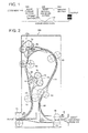
- Fig. 2 is a diagram representing the layout of the mechanism of the sheet material conveying section as an embodiment of the present invention.
- the image forming apparatus of the present invention includes at least an image forming section 100 and a sheet material conveying section 200. In a broader sense, it also includes a finishing section 300 in many cases.
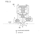
- Fig. 3 is a functional structure of the first embodiment of the sheet material conveying section 200 as a first embodiment of the present invention.
- Figs. 4(A) through (D) are the diagrams showing the operation timing of the sheet material conveying section 200 of Fig. 3 .
- Fig. 1 is a diagram representing the functional structure of the image forming apparatus as a whole.
- Fig. 2 is a diagram representing the layout of the mechanism of the sheet material conveying section as an embodiment of the present invention.
- the image forming apparatus of the present invention includes at least an image forming section 100 and a sheet material
- FIG. 5 is a functional structure of the second embodiment of the sheet material conveying section 200 as a second embodiment of the present invention.
- Fig. 6 is a variation of Fig. 5 .
- Figs. 7(A) through (D) are the diagrams showing the operation timing of the sheet material conveying section 200 of Fig. 5 .
- Figs. 8(A) and (B) are the diagrams showing the applied example of the embodiment of Fig. 3 .
- Fig. 1 shows an overall structure.
- the image forming section 100 receives a document and forms an image on a sheet material, for example, a printing sheet. After the image has been fixed by the fixing section, the sheet material is outputted to the sheet material conveying section 200.
- the sheet material conveying section 200 corrects the curl of the transfer sheet whose end has been bent (curled) by the fixing operation on the fixing section (the printing sheet with an image formed thereon, outputted from the fixing section will hereinafter be referred to as "transfer sheet").
- the sheet is then fed to the finishing section 300.
- the finishing section 300 binds the transfer sheets to a desired form or ties them in a bundle, and outputs them.
- the transfer sheet is generally conveyed from the image forming section 100 to the sheet material conveying section 200 along the conveyance path at a predetermined conveying speed.
- the transfer sheet is fed to the finishing section 300 from the sheet material conveying section 200 along the conveyance path, it is preferably fed at a speed higher than the aforementioned specified speed because a higher efficiency is ensured when there is a large amount of printing work to be handled.
- the following describes the embodiment that allows the conveying speed to be increased while correcting the curl.
- the following describes the case where one curl correcting mechanism is used (the first embodiment) and the case where two curl correcting mechanisms are used (the second embodiment). Before that, the mechanism common to both embodiments such as the curl correcting mechanism will be described first.
- (A) Mechanism and related components Description of the mechanism of each of the sheet material conveying section and curl correcting mechanism.
- FIGs. 8(A) and (B) will be used for explanation.
- A Mechanism of each of the sheet material conveying section and curl correcting mechanism
- A1 Example of using two curl correcting mechanisms
- Fig. 2 shows the case where both the first curl correcting mechanism 10a and the second curl correcting mechanism 10b are provided.
- the transfer sheet (printing sheet) fed from the image forming section 100 is fed through the first conveyance path 20 at the predetermined speed (hereinafter referred to as "initial speed vs") by the first conveyance mechanism 50.
- This initial speed vs is the same as the speed at which it is conveyed by the image forming section 100 (fixing device).
- the first conveyance mechanism 50, second conveyance mechanism 60, and third conveyance mechanism 70 are constituted by a pair of rotating rollers, respectively, which are driven by a motor.
- the transfer sheet is interposed and is fed to the next conveyance path.
- the first curl correcting mechanism 10a is constituted by: a belt 3a (endless belt); a conveying roller 1a (indicating the conveyance mechanism or belt conveying mechanism using the belt 3a and conveying roller 1a, as described in claims) composed of a pair of rotating rollers for rotating the belt; and a pressing roller 4a which moves in the direction of engagement with the belt 3a to press one of the surfaces of the transfer sheet to be held in-between with the aid of the belt 3a and to squeeze the transfer sheet, wherein this pressing roller 4a rotates.
- a motor not illustrated
- the explanation in this case assumes that the pressing roller 4a is driven and rotated.
- the pressure for pressing the transfer sheet can be adjusted by moving the pressing roller 4a to the side of the conveying roller 1a. Further, the conveying speed can be adjusted by changing the speed of the motor for driving the pressing roller 4a.
- the second conveyance mechanism 60 conveys the transfer sheet from the first curl correcting mechanism 10a to the second curl correcting mechanism 10b through the second conveyance path 30.
- the second curl correcting mechanism 10b can be designed to have the same structure as that of the first curl correcting mechanism 10a.
- the same numbers indicate the same function, although there is a difference between "a” and "b"; provided, however, that the second curl correcting mechanism 10b is located opposite to the first curl correcting mechanism 10a with the second conveyance path located in-between (they are located on the right and left opposite to each other).
- the first curl correcting mechanism 10a is arranged in such a way that the surface of the transfer sheet is pressed by the pressing roller 4a against the side engaged with the belt 3b; whereas the second curl correcting mechanism 10b is arranged in such a way that the rear surface of the transfer sheet is pressed in the direction of engagement with the belt 3b by the pressing roller 4b.
- the pressure and conveying speed can be changed as in the case of the pressing roller 4b and pressing roller 4a.
- the first curl correcting mechanism 10a and second curl correcting mechanism 10b may be arranged on the same side of the second conveyance path 30.
- the third conveyance mechanism 70 ensures that the transfer sheet having been outputted from the second curl correcting mechanism 10b to the third conveyance path 40 is conveyed from the outlet to the finishing section 300 and is outputted.
- the conveying speed is changed from the initial speed vs to the medium speed vm (vm > vs) in the first curl correcting mechanism 10a while it is holding (or applying pressure to) the transfer sheet.
- the conveying speed is from the medium speed vm to the target speed vo (vo > vm) while it is holding the transfer sheet, (wherein target speed can be defined as the speed at which the finishing section 300, for example, receives the transfer sheet).
- target speed vo is set in two phases.
- the timing of arrival is detected by the timing detection section 6 of Fig. 2 .
- the conveying speed is changed according to the timing signal created on the basis of the aforementioned detected timing, with due consideration given to the conveyance time for the sheet to be conveyed along the first conveyance path, the conveyance time for the sheet to be conveyed by the first curl correcting mechanism 10a, and the conveyance time for the sheet to be conveyed by the second curl correcting mechanism 10b.
- the pressure when the transfer sheet is interposing by the first curl correcting mechanism 10a and the second curl correcting mechanism 10b is constant for the time. Further, the first curl correcting mechanism 10a reverses the curl of the transfer sheet having been conveyed. The transfer sheet provided with reversed curl is fed to the second curl correcting mechanism 10b, and the second curl correcting mechanism 10b finally corrects the curl (reversed curl) of the transfer sheet. (Details will be described later with reference to the second embodiment). (A2: Example of using only one curl correcting mechanism)
- the conveying speed is changed from the initial speed vs to the target speed vo (vo > vs) (set to vo in one step) in such a way that the pressure is also increased in proportion.
- the timing of the arrival is detected by the timing detection section 6 of Fig. 2 , and the timing of changing the speed is determined according to the timing signal on the basis of the aforementioned timing, with due consideration given to the conveyance time for the sheet to be conveyed along the first conveyance path. (Details will be described later with reference to the first embodiment).
- Each of the curl correcting mechanisms of Fig. 2 can be designed in such a way that the conveying rollers 1a and 1b are driven by a motor for the conveyance of the sheet.
- the pressing rollers 4a and 4b can be designed in such a way that the pressure is changed in conformity to the amount of rotation, using an eccentricity cam.
- the first curl correcting mechanism 10a and the second curl correcting mechanism 10b are not required to be identically the same with each other. A variation may be used.
- belts 3a and 3b are used on one side to sandwich the sheet. This is intended to provide elasticity to convey the transfer sheet by pressing it with metallic pressing rollers 4a and 4b. To be more specific, the elasticity is provided by the tension of the belts 3a and 3b applied between a pair of metallic rotating rollers constituting the conveying rollers 1a and 1b.
- Each of the conveying rollers 1a and 1b is constituted by one (or two) rotating roller(s).
- the circumferential portion of the rotating roller interposing the transfer sheet is made of an elastic member such as a sponge.
- the metallic pressing rollers 4a and 4b holding the transfer sheet in-between are pressed toward the elastic member, which is then conveyed (not illustrated).
- the timing detection section 6 of Fig. 3 When the timing detection section 6 of Fig. 3 is located at the inlet wherein the transfer sheet is conveyed to the first curl correcting mechanism 10a, it generates the timing signal for the timing having been detected or the timing slightly delayed, and sends it to the controller 7a. In this case, however, when the timing detection section 6 is located at the forward inlet beyond the first conveyance path 20 as shown in Fig. 2 , the time for conveying along the first conveyance path is calculated in advance, based on the conveying speed at the inlet (or is stored in the memory section). The arrival timing is detected at the inlet.
- the timing detection section 6 generates the timing signal indicating the time elapsed for conveyance along the first conveyance path from the time of arrival (wherein the controller 7a can be used to generate this timing signal). This timing signal is then sent to the controller 7a.
- the timing signal of Fig. 4(A) As shown in Fig. 4(A) , the timing can be time t1 when the sheet enters the first curl correcting mechanism, or time t2 which is slightly delayed.
- the speed control section 71a stores in advance the conveying speed of the transfer sheet when it passes through the first conveyance path from the image forming section 100 (this speed may be determined by the image forming section 100; hereinafter referred to as "initial speed vs"); and the conveying speed for conveying the sheet to the finishing section 300 through the second conveyance path 30 and the third conveyance path 40 (this speed may be determined by the finishing section 300; hereinafter referred to as "target speed vo").
- the timing signal is received at time t2. Then the timing and the amount of control for increasing the conveying speed from the initial speed vs to the target speed vo upon receipt of this signal are sent to the conveyance and drive section 2a.
- the conveyance and drive section 2a is made of a motor for driving the pressing roller 4a, for example. It increases the rotation speed by the amount of control specified at time t2. As a result, the pressing roller 4a conveys the transfer sheet at the target speed vo. Based on the information of the relationship between the rotation speed and conveying speed (so-called linear speed in contrast to the rotation speed), the speed control section 71a obtains the amount of control by computation (the amount of control equivalent to vo - vs).
- Fig. 4(B) shows the timing for the conveying speed. The speed is changed at least during the time when the first curl correcting mechanism 10a holds the transfer sheet (from t1 through t2 in Fig. 4(A) ), subsequent to startup of holding the transfer sheet in-between.
- the pressure control section 72a sends the instruction for movement by a predetermined distance (a predetermined amount of rotation in the case of an eccentric cam) to the pressing and driving section 5a at time t2.
- the pressing roller 4a is moved by the specified amount of distance, thereby increasing the pressure applied to the transfer sheet.
- the pressing and driving section 5a is provided with a moving mechanism in the present example.
- the pressure control section 72a stores the value obtained empirically in advance as the specified predetermined amount of movement.
- the time when the pressure is changed by the pressure control section 72a is the same as the time when the speed is changed by the speed control section 71a.
- the time when the pressure is changed is described as the same as the time when the speed is changed. However, the time of applying the pressure and the pressure can be changed as required, based on the value empirically given in advance.
- the conveying speed of the transfer sheet in Fig. 4(B) is transferred to the second conveyance mechanism 60 after the time t3 for terminating the holding of the transfer sheet in-between.
- the sheet is fed at the target speed vo.
- the belt speed of Fig. 4(C) and the pressure of Fig. 4(D) are returned to the levels before time t2.
- the system waits for the arrival of the next transfer sheet.
- the time t3 can be detected by a detecting device. It can also be generated by the timing detection section 6 or the controller 7a, based on the timing of arrival detected by the timing detection section 6. This does not require high precision. It is sufficient only if the aforementioned belt speed and pressure come back to the original levels at least before the arrival of the next transfer sheet.
- the following describes the art of using two curl correcting mechanisms to correct the curl based on the functional structure of Fig. 5 and the timing chart of Fig. 7 , and increasing the conveying speed.
- the first curl correcting mechanism 10a of Fig. 5 is the same as that of Fig. 3 .
- the second curl correcting mechanism 10b also have the same functions as those of the first curl correcting mechanism 10a, for the blocks having the same reference numerals, although the letters of the references are different. However, differences are found in conveying speed and pressure in both cases.
- One timing detection section 6 of Fig, 5 is located at the inlet through which the transfer sheet enters the first curl correcting mechanism 10a (See Fig. 2 ). Two types of timing signal having been detected are generated. One of them is a timing signal to be sent to the controller 7a. In this case, similarly to the case of the first embodiment, the timing detection section 6 detects the timing signal for the time of arrival. The timing detection section 6 supplies the controller 7a with the timing signal indicating the time elapsed for conveyance along the first conveyance path, based on that timing (e.g. time t2 of Fig. 7(A) ). This conveyance time can be obtained by calculation or can be stored in advance. The other type is a timing signal to be sent to the controller 7b.
- the timing detection section 6 generates a timing signal which is delayed by the time calculated by the addition of the time for conveyance along the first conveyance path 20, the time for conveyance by the first curl correcting mechanism 10a and the conveyance time for conveyance along the second conveyance path (e.g. time t5 of Fig. 7(A) ).
- the transfer sheet is conveyed along the first conveyance path 20 at the initial speed vs and along the second conveyance path 30 at the medium speed vm (vo > vm > vs).
- the sheet is further conveyed through the first curl correcting mechanism 10a at both the initial speed vs and the medium speed vm.
- each conveyance time is obtained in advance from the conveying speed and the length of each conveyance path. It is also possible to store the conveyance time measured in advance.
- the speed control section 71a stores in advance the initial speed vs an the medium speed vm of the transfer sheet passing through the first conveyance path 20 from the image forming apparatus 100. Interposing of the transfer sheet starts at time t1. After that, the timing signal is received at time t2. Upon receipt of this timing signal, the timing and the amount of control (the amount of control corresponding to vm - vs) for increasing the conveying speed from the initial speed vs to the medium speed vm are sent to the conveyance and drive section 2a. The conveyance and drive section 2a provides control by the amount of control specified at time t2, and increases the rotation speed of the pressing roller 4a.
- the pressing roller 4a conveys the transfer sheet at the medium speed vm (See Fig. 7(B) ).
- speed change by the speed control section 71a is carried out at least while the transfer sheet is interposed by the first curl correcting mechanism 10a (from t1 through t3 in Fig. 7(B) ).
- the speed control section 71b stores in advance the medium speed vm and target speed vo of the transfer sheet conveyed along the second conveyance path 30. Interposing of the transfer sheet starts at time t4. After that, the timing signal is received at time t5. Upon receipt of this timing signal, the timing and the amount of control (the amount of control corresponding to vm - vs) for increasing the conveying speed from the medium speed vm to the target speed vo are sent to the conveyance and drive section 2b. The conveyance and drive section 2b provides control by the amount of control specified at time t5, and increases the rotation speed of the pressing roller 4b. As a result, the pressing roller 4b conveys the transfer sheet at the target speed vo (See Fig. 7(B) ). It should be noted that speed change by the speed contrcl section 71b is carried out at least while the transfer sheet is interposed by the second curl correcting mechanism 10b (from t4 through t6 in Fig. 7(B) ).
- the first speed described in claims corresponds to the initial speed vs (or the medium speed vm), and the second speed described in claims corresponds to either the medium speed vm or target speed vo.
- Each of the pressure control sections 72a and 72b controls the pressing and driving sections 5a and 5b in such a way that a predetermined pressure is applied with reference to time, independently of the timing ( Fig. 7(D) ).
- the pressing roller 4a and pressing roller 4b apply pressure to the surfaces of the transfer sheet opposite to each other, thereby correcting the curl through mutual cooperation.
- the pressure control sections 72a and 72b control the pressing roller drive section 5a in such a way the first curl correcting mechanism 10a will apply pressure so as to provide a curl reverse to that of the transfer sheet having reached.
- each of the pressure control sections 72a and 72b controls the pressing and driving section 5b to ensure that the reversed curl of the transfer sheet is finally corrected by the second curl correcting mechanism 10b ( Fig. 5 ).
- These pressures are determined empirically with respect to the speed.
- the conveying speed of the second curl correcting mechanism 10b is higher than that of the first curl correcting mechanism 10a. Accordingly, the pressure of the first curl correcting mechanism 10a is adjusted to ensure that the curl of the leading edge of the transfer sheet reaching the second curl correcting mechanism 10b will be strong, and the curl of the trailing edge will be weak, as shown in the enlarged view of Fig. 5 .
- the second curl correcting mechanism 10b is adjusted to the pressure for correcting the curl of the leading edge of the transfer sheet to be conveyed.
- the pressure control section 72a may allow a slight change of the pressure of the pressing roller 4a.
- the transfer sheet conveyance speed of Fig. 7(B) is transferred to the second conveyance mechanism 60 after the time t3 when the first curl correcting mechanism 10a terminates interposing of the transfer sheet.
- the sheet is fed at the medium speed vm.
- the transfer sheet conveyance speed is transferred to the third conveyance mechanism 70 after the time t6 when the second curl correcting mechanism 10b terminates interposing of the transfer sheet.
- the sheet is fed at the target speed vo.
- the speed of the belt 3a is returned to the level before time t2. Then the system waits for the arrival of the next transfer sheet.
- time t6 the speed of the belt 3b is returned to the level before time t5.
- Times t3 and t6 can be detected by a detecting device, or can be generated by the timing detection section 6 or the controllers 7a and 7b, based on the timing of arrival detected by the timing detection section 6a.
- Fig. 6 shows a variation of the method of providing timing shown in Fig. 5 .
- the difference between Fig. 6 and Fig. 5 is that, in Fig. 6 , the timing detection section 6a and the timing detection section 6b are installed at the portion of the first curl correcting mechanism 10a and the second curl correcting mechanism 10b where the transfer sheet enters. Accordingly, in each of the curl correcting mechanisms 10a and 10b, the timing of changing the conveying speed can be set to the timing detected by the timing detection section 6a and the timing detection section 6b, or to the timing delayed as desired. To be more specific, there is no conveyance path between the timing detection sections 6a and 6b, and the curl correcting mechanisms 10a and 10b. This eliminates the need for the timing signal to incorporate the conveyance time along the conveyance path.
- Figs. 8(A) and 8(B) show the examples of using the invention of Fig. 3 for two-sided printing on the transfer sheet.
- the first curl correcting mechanism 10a is utilized.
- Two mechanisms having the same structure as that of Fig. 3 are employed. It should be noted, however, that at least either the conveying speed or pressure require adjustment. The following describes the procedure of two-sided printing operations.
- one first curl correcting mechanism 10a is located on the side of the main route 600, and also serves the function of the first curl correcting mechanism 10a located on the returning route given in Fig. 8(A) .
- the first curl correcting mechanism 10a differs in the conveying speed and pressure according to whether the transfer sheet is outputted to the two-sided print sheet conveyance path (returning conveyance path), or it is ejected to the finishing section 300. Control must be provided on a time division basis as shown in the aforementioned (2) in the former case, and as shown in the aforementioned (4) in the latter case.
- the second conveyance path change section 500 may be included in the composition of the main route 600 and returning route 700 shown in Figs. 8(A) and 8(B) .
- This composition is practically the same as that of the image forming apparatus as shown in Fig. 3 and Fig. 1 .
- an image is formed on the rear surface after the curl produced subsequent to fixing of the image on the surface has been corrected. This arrangement minimizes deviations in dimensions caused by curling.
- the controllers 7a and 7b in each of the aforementioned embodiments can be constructed of a CPU and a memory storing the program for allowing the CPU to execute the aforementioned processing functions.
- the present embodiment increases the sheet material conveying speed and the pressure to the sheet material for uncurling, during the correction by a curl correcting mechanism. This arrangement corrects the curl of the sheet material and improves the productivity (conveying speed) at the same time.
- the curl is first corrected by a correcting mechanism along the returning conveyance path, and an image is then formed on the other surface.
Landscapes
- Physics & Mathematics (AREA)
- General Physics & Mathematics (AREA)
- Engineering & Computer Science (AREA)
- Mechanical Engineering (AREA)
- Separation, Sorting, Adjustment, Or Bending Of Sheets To Be Conveyed (AREA)
- Paper Feeding For Electrophotography (AREA)
Abstract
An image forming apparatus comprising: an image forming section which forms an image on a sheet material; a curl correcting mechanism which interposes and conveys the sheet material on which the image has been formed by the image forming section. Pressure applied to one surface of the sheet material during an interposing operation and a conveying speed of the sheet material can be changed, the curl correcting mechanism changes the conveying speed from an initial speed vs to a target speed vo higher than the initial speed (vo > vs) while the sheet material is pressed, and the curl correcting mechanism changes the pressure to a high pressure in response to a change of the conveying speed, whereby a curl of the sheet material is reduced.
Description
- The present invention relates to an image forming apparatus including a single machine function of a printer, a copying machine or facsimile machine, or multi-function thereof, an image forming method, and a sheet material conveyance device used therein, particularly to the art of improving the productivity by correcting the curl of the sheet material with an image formed thereon, and contributing to formation of great quantities of images by increasing the conveying speed.
- When a sheet material on which an image has been formed passes through the fixing unit of an image forming apparatus, the sheet material will be curled during the passage through the fixing unit. One of the conventional ways of correcting the curl uses a curl correcting member, wherein the sheet material is conveyed by turning the belt with a conveying roller, and to pressing the sheet material conveyed by the belt in one direction using a rotatable pressing roller, whereby the sheet material is interposed and uncurled. If this procedure fails to correct the curl, the direction of conveyance is switched and the surface of the sheet material pressed by the pressing roller is changed. Then the sheet material is again passed through the curl correction device, whereby the sheet is uncurled (
Patent Document 1, i.e., Official Gazette of Japanese PatentTokkaihei 10-114454 - According to another conventional way of correcting the curl, a sheet material is interposed between a conveying member and a curling member during the conveyance wherein the ends of the sheet material are held. In this state, the conveyance speed of sheet material is reduced, and the sheet is uncurled (Patent Document 2, i.e., Official Gazette of Japanese Patent
Tokkaihei 11-193160 - Separately from the aforementioned conventional art, it is required to increase the conveying speed and to improve productivity. When these requirements are to be met by the conventional image forming apparatus, it will be necessary to increase the conveying speed using a curl correcting mechanism and to install another conveyance mechanism on the downstream side thereof. When the art of the
Patent Document 1, for example, is used to meet the former requirement, the sheet material is interposed (pressed). When this pressure has reached a predetermined level, the conveying speed is increased. This procedure allows a curl to remain on the trailing edge of the sheet material. To meet the latter requirement, the size of the apparatus has to be increased by the addition of another conveyance mechanism. These problems remain unsolved when the aforementioned requirements are to be met. - The object of the present invention is to provide the technology of reducing the curl and improving the productivity by ensuring that the conveying speed and the pressure for curl correction can be changed while a curl is corrected by a curl correcting mechanism.
- The following structures are provided to achieve the aforementioned object.
- (1) An image forming apparatus includes: an image forming section for forming an image on a sheet material; and a curl correcting mechanism for interposing and conveying the aforementioned sheet material on which an image is formed by the aforementioned image forming section, wherein the sheet material interposing pressure and conveying speed can be changed; wherein the curl correcting mechanism conveys the sheet material by changing the aforementioned conveying speed from the initial speed vs to the target speed vo (vo > vs) while the aforementioned sheet material is pressed, and changing the aforementioned pressure to a high pressure in response to the speed change, whereby the curl of the aforementioned sheet material is reduced.
- (2) An image forming apparatus includes: an image forming section for forming an image on a sheet material; a curl correcting mechanism for interposing and conveying the aforementioned sheet material on which an image is formed by the aforementioned image forming section, wherein the pressure applied to one surface of the sheet material during the interposing operation and conveying speed can be changed; a timing detection section for detecting the timing when the sheet material with an image formed thereon is interposed by the aforementioned curl correcting mechanism, and for outputting the timing signal for changing the aforementioned conveying speed; and a controller for providing control in such a way that, upon receipt of the aforementioned timing signal, the aforementioned curl correcting mechanism changes the conveying speed from the initial speed vs to a higher speed as the target speed vo (vo > vs) and increases the aforementioned pressure in response to the new conveying speed.
- (3) An image forming apparatus includes: an image forming section for forming an image on a sheet material; a first curl correcting mechanism for interposing and conveying the aforementioned sheet material on which an image is formed by the aforementioned image forming section, wherein the pressure applied to one surface of the sheet material and the conveying speed can be changed; and a second curl correcting mechanism, located downstream of the aforementioned first curl correcting mechanism, for interposing and conveying the aforementioned sheet material, wherein the pressure is applied to other surface opposite to the aforementioned one surface of the sheet material, and the conveying speed can be changed; wherein the aforementioned first curl correcting mechanism changes the aforementioned conveying speed from the initial speed vs to a higher speed as the medium speed vm (vm > vs) while pressing the sheet material; and the aforementioned second curl correcting mechanism changes the aforementioned conveying speed from the aforementioned medium speed vm to a higher speed as the target speed vo (vo > vm) while pressing the sheet material, whereby the curl of the aforementioned sheet material is reduced.
- (4) An image forming apparatus includes: an image forming section for forming an image on a sheet material; a conveyance path for conveying the sheet material with an image formed thereon by the aforementioned image forming section, a first curl correcting mechanism, located on the aforementioned conveyance path, provided with a first belt conveying mechanism; and a first roller member for applying pressure to one side of the sheet material being conveyed, in the direction of engagement with the first belt of the aforementioned first belt conveying mechanism; wherein the conveying speed can be changed by driving either the aforementioned first belt conveying mechanism or the first roller member; a second the curl correcting mechanism which receives the sheet material outputted from the first curl correcting mechanism and is provided with a second belt conveying mechanism, and a second roller member for applying pressure to the side opposite to the aforementioned surface of the aforementioned sheet material being conveyed, in the direction of engagement with the second belt of the aforementioned second belt mechanism; wherein the conveying speed can be changed by driving either the aforementioned second belt conveying mechanism or the second roller member; a timing detection section for outputting the first timing signal showing the timing when the sheet material with an image formed thereon is interposed by the first belt and the first roller member, and the second timing signal showing the timing when the sheet material with an image formed thereon is interposed by the second belt and the second roller member; a first speed control section which, upon receipt of the first timing signal, controls the aforementioned first curl correcting mechanism to change the conveying speed from the initial speed vs to the medium speed vm (vm > vs); and a second speed control section which, upon receipt of the second timing signal, controls the second curl correcting mechanism to change the conveying speed from the aforementioned medium speed vm to target speed vo (vo > vm).
- (5) An image forming apparatus includes: an image forming section for forming an image on a sheet material; a returning conveyance path for reversing the sheet material with an image formed on one surface thereof by the aforementioned image forming section, and for conveying it back to the aforementioned image forming section so as to print on the rear surface; a curl correcting mechanism on the returning side, located on the aforementioned returning conveyance path, for interposing and rotating the sheet material having an image formed on the aforementioned one surface, and for conveying it by applying a predetermined interposing pressure; a curl correcting mechanism which, upon receipt of the sheet material with images formed on both surfaces by the aforementioned image forming section, sandwiches, rotates and conveys the aforementioned sheet material, wherein pressure applied to the sheet material during an interposing operation and a conveying speed of the sheet material can be changed, and the curl correcting mechanism changes the aforementioned conveying speed from the initial speed vs to the target speed vo (vo > vs) while the aforementioned sheet material is pressed, and increases the pressure in conformity to the new speed, wherein the interposing pressure and the conveying speed can be changed.
- (6) A sheet material conveying device includes: a conveyance mechanism for elastic interposing the sheet material with an image formed thereon; a roller member for pressing one surface of the aforementioned sheet material conveyed at the first speed against the aforementioned conveyance mechanism and interposing the sheet material, a curl correcting mechanism for driving the aforementioned conveyance mechanism or roller member in such a way that the conveying speed can be changed; wherein the aforementioned conveying speed is changed from the first speed to the second faster than the first speed while pressure is applied to the aforementioned sheet material, and the sheet material is conveyed.
-
-
Fig. 1 is a diagram representing the functional structure of the image forming apparatus as a whole; -
Fig. 2 is a diagram representing the layout of the mechanism of the sheet material conveying section (sheet material conveyance device) as embodiment of the present invention; -
Fig. 3 is a functional structure of the first embodiment of the sheetmaterial conveying section 200 according to the present invention; -
Figs. 4(A) through (D) are the diagrams showing the operation timing of the sheetmaterial conveying section 200 ofFig. 3 ; -
Fig. 5 is a functional structure of the second embodiment of the sheetmaterial conveying section 200 according to the present invention; -
Fig. 6 is a variation ofFig. 5 ; -
Figs. 7(A) through (D) are the diagrams showing the operation timing of the sheetmaterial conveying section 200 ofFig. 5 ; and -
Figs. 8(A) and (B) are the diagrams showing the applied example of the embodiment ofFig. 3 . - Referring to
Fig. 1 , the following describes the embodiment of the present invention.Fig. 1 is a diagram representing the functional structure of the image forming apparatus as a whole.Fig. 2 is a diagram representing the layout of the mechanism of the sheet material conveying section as an embodiment of the present invention. The image forming apparatus of the present invention includes at least animage forming section 100 and a sheetmaterial conveying section 200. In a broader sense, it also includes afinishing section 300 in many cases.Fig. 3 is a functional structure of the first embodiment of the sheetmaterial conveying section 200 as a first embodiment of the present invention.Figs. 4(A) through (D) are the diagrams showing the operation timing of the sheetmaterial conveying section 200 ofFig. 3 .Fig. 5 is a functional structure of the second embodiment of the sheetmaterial conveying section 200 as a second embodiment of the present invention.Fig. 6 is a variation ofFig. 5 .Figs. 7(A) through (D) are the diagrams showing the operation timing of the sheetmaterial conveying section 200 ofFig. 5 .Figs. 8(A) and (B) are the diagrams showing the applied example of the embodiment ofFig. 3 . - The following describes the schematic arrangement of the embodiment of the image forming apparatus with reference to
Fig. 1. Fig. 1 shows an overall structure. Theimage forming section 100 receives a document and forms an image on a sheet material, for example, a printing sheet. After the image has been fixed by the fixing section, the sheet material is outputted to the sheetmaterial conveying section 200. The sheetmaterial conveying section 200 corrects the curl of the transfer sheet whose end has been bent (curled) by the fixing operation on the fixing section (the printing sheet with an image formed thereon, outputted from the fixing section will hereinafter be referred to as "transfer sheet"). The sheet is then fed to thefinishing section 300. Thefinishing section 300 binds the transfer sheets to a desired form or ties them in a bundle, and outputs them. - In this case, the transfer sheet is generally conveyed from the
image forming section 100 to the sheetmaterial conveying section 200 along the conveyance path at a predetermined conveying speed. When the transfer sheet is fed to thefinishing section 300 from the sheetmaterial conveying section 200 along the conveyance path, it is preferably fed at a speed higher than the aforementioned specified speed because a higher efficiency is ensured when there is a large amount of printing work to be handled. The following describes the embodiment that allows the conveying speed to be increased while correcting the curl. - The following describes the case where one curl correcting mechanism is used (the first embodiment) and the case where two curl correcting mechanisms are used (the second embodiment). Before that, the mechanism common to both embodiments such as the curl correcting mechanism will be described first.
- This will be described with reference to
Fig. 2 , where two curl correcting mechanisms are utilized. The case of two curl correcting mechanisms will be described first, and the case of one curl correcting mechanisms will be described thereafter. - The function structure diagram of
Fig. 3 and timing chart ofFigs. 4(A) through (D) will be used for description. - The function structure diagram of
Fig. 5 and timing chart ofFigs. 7(A) through (D) will be used for description. The variation of the example will be described with reference toFig. 6 . -
Figs. 8(A) and (B) will be used for explanation. (A: Mechanism of each of the sheet material conveying section and curl correcting mechanism) (A1: Example of using two curl correcting mechanisms) - Referring to
Fig. 2 , the following describes the mechanism of the sheetmaterial conveying section 200.Fig. 2 shows the case where both the firstcurl correcting mechanism 10a and the secondcurl correcting mechanism 10b are provided. - In
Fig. 2 , the transfer sheet (printing sheet) fed from theimage forming section 100 is fed through thefirst conveyance path 20 at the predetermined speed (hereinafter referred to as "initial speed vs") by thefirst conveyance mechanism 50. This initial speed vs is the same as the speed at which it is conveyed by the image forming section 100 (fixing device). Thefirst conveyance mechanism 50,second conveyance mechanism 60, andthird conveyance mechanism 70 are constituted by a pair of rotating rollers, respectively, which are driven by a motor. The transfer sheet is interposed and is fed to the next conveyance path. - The first
curl correcting mechanism 10a is constituted by: abelt 3a (endless belt); a conveyingroller 1a (indicating the conveyance mechanism or belt conveying mechanism using thebelt 3a and conveyingroller 1a, as described in claims) composed of a pair of rotating rollers for rotating the belt; and apressing roller 4a which moves in the direction of engagement with thebelt 3a to press one of the surfaces of the transfer sheet to be held in-between with the aid of thebelt 3a and to squeeze the transfer sheet, wherein thispressing roller 4a rotates. To convey the transfer sheet, either thepressing roller 4a or conveyingroller 1a is driven by a motor (not illustrated). Then the other is also rotated. The explanation in this case assumes that thepressing roller 4a is driven and rotated. The pressure for pressing the transfer sheet can be adjusted by moving thepressing roller 4a to the side of the conveyingroller 1a. Further, the conveying speed can be adjusted by changing the speed of the motor for driving thepressing roller 4a. - The
second conveyance mechanism 60 conveys the transfer sheet from the firstcurl correcting mechanism 10a to the secondcurl correcting mechanism 10b through thesecond conveyance path 30. - The second
curl correcting mechanism 10b can be designed to have the same structure as that of the firstcurl correcting mechanism 10a. The same numbers indicate the same function, although there is a difference between "a" and "b"; provided, however, that the secondcurl correcting mechanism 10b is located opposite to the firstcurl correcting mechanism 10a with the second conveyance path located in-between (they are located on the right and left opposite to each other). Namely, the firstcurl correcting mechanism 10a is arranged in such a way that the surface of the transfer sheet is pressed by thepressing roller 4a against the side engaged with thebelt 3b; whereas the secondcurl correcting mechanism 10b is arranged in such a way that the rear surface of the transfer sheet is pressed in the direction of engagement with thebelt 3b by thepressing roller 4b. It should be noted that the pressure and conveying speed can be changed as in the case of thepressing roller 4b andpressing roller 4a. - When the direction of the transfer sheet surface cannot be changed between the first
curl correcting mechanism 10a and secondcurl correcting mechanism 10b, namely, along thesecond conveyance path 30, the firstcurl correcting mechanism 10a and secondcurl correcting mechanism 10b may be arranged on the same side of thesecond conveyance path 30. - The
third conveyance mechanism 70 ensures that the transfer sheet having been outputted from the secondcurl correcting mechanism 10b to thethird conveyance path 40 is conveyed from the outlet to thefinishing section 300 and is outputted. - In the example wherein the first
curl correcting mechanism 10a and the secondcurl correcting mechanism 10b are operated simultaneously, the conveying speed is changed from the initial speed vs to the medium speed vm (vm > vs) in the firstcurl correcting mechanism 10a while it is holding (or applying pressure to) the transfer sheet. In the second thecurl correcting mechanism 10b, the conveying speed is from the medium speed vm to the target speed vo (vo > vm) while it is holding the transfer sheet, (wherein target speed can be defined as the speed at which thefinishing section 300, for example, receives the transfer sheet). The target speed vo is set in two phases. The timing of arrival is detected by thetiming detection section 6 ofFig. 2 . Then the conveying speed is changed according to the timing signal created on the basis of the aforementioned detected timing, with due consideration given to the conveyance time for the sheet to be conveyed along the first conveyance path, the conveyance time for the sheet to be conveyed by the firstcurl correcting mechanism 10a, and the conveyance time for the sheet to be conveyed by the secondcurl correcting mechanism 10b. - In this case, however, the pressure when the transfer sheet is interposing by the first
curl correcting mechanism 10a and the secondcurl correcting mechanism 10b is constant for the time. Further, the firstcurl correcting mechanism 10a reverses the curl of the transfer sheet having been conveyed. The transfer sheet provided with reversed curl is fed to the secondcurl correcting mechanism 10b, and the secondcurl correcting mechanism 10b finally corrects the curl (reversed curl) of the transfer sheet. (Details will be described later with reference to the second embodiment). (A2: Example of using only one curl correcting mechanism) - This is the case where only the first
curl correcting mechanism 10a is enabled (wherein the second thecurl correcting mechanism 10b is disabled). In this case, only one curl correcting mechanism is available, so only the firstcurl correcting mechanism 10a ofFig. 2 is operated. It corresponds to the case where the secondcurl correcting mechanism 10b is not provided, or the case where the secondcurl correcting mechanism 10b is not used even if the secondcurl correcting mechanism 10b is provided. When the firstcurl correcting mechanism 10a is operating independently, there is no difference from the case where it operates together with the secondcurl correcting mechanism 10b. However, there is a difference in the conveying speed and pressure when the transfer sheet is interposed. - To be more specific, the conveying speed is changed from the initial speed vs to the target speed vo (vo > vs) (set to vo in one step) in such a way that the pressure is also increased in proportion. The timing of the arrival is detected by the
timing detection section 6 ofFig. 2 , and the timing of changing the speed is determined according to the timing signal on the basis of the aforementioned timing, with due consideration given to the conveyance time for the sheet to be conveyed along the first conveyance path. (Details will be described later with reference to the first embodiment). - Each of the curl correcting mechanisms of
Fig. 2 can be designed in such a way that the conveyingrollers pressing rollers curl correcting mechanism 10a and the secondcurl correcting mechanism 10b are not required to be identically the same with each other. A variation may be used. - In
Fig. 2 ,belts pressing rollers belts rollers - Such being the case, the following arrangement can also be adopted. Each of the conveying
rollers pressing rollers - The following describes the case wherein, based on the functional structure of
Fig. 3 and the timing chart ofFigs. 4(A) through 4(D) , only one curl correcting mechanism, that is, the firstcurl correcting mechanism 10a ofFig. 2 is used to correct the curl, and the conveying speed is increased. - When the
timing detection section 6 ofFig. 3 is located at the inlet wherein the transfer sheet is conveyed to the firstcurl correcting mechanism 10a, it generates the timing signal for the timing having been detected or the timing slightly delayed, and sends it to thecontroller 7a. In this case, however, when thetiming detection section 6 is located at the forward inlet beyond thefirst conveyance path 20 as shown inFig. 2 , the time for conveying along the first conveyance path is calculated in advance, based on the conveying speed at the inlet (or is stored in the memory section). The arrival timing is detected at the inlet. Thetiming detection section 6 generates the timing signal indicating the time elapsed for conveyance along the first conveyance path from the time of arrival (wherein thecontroller 7a can be used to generate this timing signal). This timing signal is then sent to thecontroller 7a. Refer to the timing signal ofFig. 4(A) . As shown inFig. 4(A) , the timing can be time t1 when the sheet enters the first curl correcting mechanism, or time t2 which is slightly delayed. - The
speed control section 71a stores in advance the conveying speed of the transfer sheet when it passes through the first conveyance path from the image forming section 100 (this speed may be determined by theimage forming section 100; hereinafter referred to as "initial speed vs"); and the conveying speed for conveying the sheet to thefinishing section 300 through thesecond conveyance path 30 and the third conveyance path 40 (this speed may be determined by thefinishing section 300; hereinafter referred to as "target speed vo"). For example, the timing signal is received at time t2. Then the timing and the amount of control for increasing the conveying speed from the initial speed vs to the target speed vo upon receipt of this signal are sent to the conveyance and drivesection 2a. The conveyance and drivesection 2a is made of a motor for driving thepressing roller 4a, for example. It increases the rotation speed by the amount of control specified at time t2. As a result, thepressing roller 4a conveys the transfer sheet at the target speed vo. Based on the information of the relationship between the rotation speed and conveying speed (so-called linear speed in contrast to the rotation speed), thespeed control section 71a obtains the amount of control by computation (the amount of control equivalent to vo - vs).Fig. 4(B) shows the timing for the conveying speed. The speed is changed at least during the time when the firstcurl correcting mechanism 10a holds the transfer sheet (from t1 through t2 inFig. 4(A) ), subsequent to startup of holding the transfer sheet in-between. - As indicated by
Fig. 4(D) , thepressure control section 72a sends the instruction for movement by a predetermined distance (a predetermined amount of rotation in the case of an eccentric cam) to the pressing anddriving section 5a at time t2. Thepressing roller 4a is moved by the specified amount of distance, thereby increasing the pressure applied to the transfer sheet. The pressing anddriving section 5a is provided with a moving mechanism in the present example. Thepressure control section 72a stores the value obtained empirically in advance as the specified predetermined amount of movement. The time when the pressure is changed by thepressure control section 72a is the same as the time when the speed is changed by thespeed control section 71a. The time when the pressure is changed is described as the same as the time when the speed is changed. However, the time of applying the pressure and the pressure can be changed as required, based on the value empirically given in advance. - The conveying speed of the transfer sheet in
Fig. 4(B) is transferred to thesecond conveyance mechanism 60 after the time t3 for terminating the holding of the transfer sheet in-between. The sheet is fed at the target speed vo. After time t3, the belt speed ofFig. 4(C) and the pressure ofFig. 4(D) are returned to the levels before time t2. Then the system waits for the arrival of the next transfer sheet. The time t3 can be detected by a detecting device. It can also be generated by thetiming detection section 6 or thecontroller 7a, based on the timing of arrival detected by thetiming detection section 6. This does not require high precision. It is sufficient only if the aforementioned belt speed and pressure come back to the original levels at least before the arrival of the next transfer sheet. - The following describes the art of using two curl correcting mechanisms to correct the curl based on the functional structure of
Fig. 5 and the timing chart ofFig. 7 , and increasing the conveying speed. The firstcurl correcting mechanism 10a ofFig. 5 is the same as that ofFig. 3 . The secondcurl correcting mechanism 10b also have the same functions as those of the firstcurl correcting mechanism 10a, for the blocks having the same reference numerals, although the letters of the references are different. However, differences are found in conveying speed and pressure in both cases. - One
timing detection section 6 ofFig, 5 is located at the inlet through which the transfer sheet enters the firstcurl correcting mechanism 10a (SeeFig. 2 ). Two types of timing signal having been detected are generated. One of them is a timing signal to be sent to thecontroller 7a. In this case, similarly to the case of the first embodiment, thetiming detection section 6 detects the timing signal for the time of arrival. Thetiming detection section 6 supplies thecontroller 7a with the timing signal indicating the time elapsed for conveyance along the first conveyance path, based on that timing (e.g. time t2 ofFig. 7(A) ). This conveyance time can be obtained by calculation or can be stored in advance. The other type is a timing signal to be sent to thecontroller 7b. In this case, thetiming detection section 6 generates a timing signal which is delayed by the time calculated by the addition of the time for conveyance along thefirst conveyance path 20, the time for conveyance by the firstcurl correcting mechanism 10a and the conveyance time for conveyance along the second conveyance path (e.g. time t5 ofFig. 7(A) ). In this case, as will be described later, the transfer sheet is conveyed along thefirst conveyance path 20 at the initial speed vs and along thesecond conveyance path 30 at the medium speed vm (vo > vm > vs). The sheet is further conveyed through the firstcurl correcting mechanism 10a at both the initial speed vs and the medium speed vm. Thus, each conveyance time is obtained in advance from the conveying speed and the length of each conveyance path. It is also possible to store the conveyance time measured in advance. - The
speed control section 71a stores in advance the initial speed vs an the medium speed vm of the transfer sheet passing through thefirst conveyance path 20 from theimage forming apparatus 100. Interposing of the transfer sheet starts at time t1. After that, the timing signal is received at time t2. Upon receipt of this timing signal, the timing and the amount of control (the amount of control corresponding to vm - vs) for increasing the conveying speed from the initial speed vs to the medium speed vm are sent to the conveyance and drivesection 2a. The conveyance and drivesection 2a provides control by the amount of control specified at time t2, and increases the rotation speed of thepressing roller 4a. As a result, thepressing roller 4a conveys the transfer sheet at the medium speed vm (SeeFig. 7(B) ).. It should be noted that speed change by thespeed control section 71a is carried out at least while the transfer sheet is interposed by the firstcurl correcting mechanism 10a (from t1 through t3 inFig. 7(B) ). - The
speed control section 71b stores in advance the medium speed vm and target speed vo of the transfer sheet conveyed along thesecond conveyance path 30. Interposing of the transfer sheet starts at time t4. After that, the timing signal is received at time t5. Upon receipt of this timing signal, the timing and the amount of control (the amount of control corresponding to vm - vs) for increasing the conveying speed from the medium speed vm to the target speed vo are sent to the conveyance and drivesection 2b. The conveyance and drivesection 2b provides control by the amount of control specified at time t5, and increases the rotation speed of thepressing roller 4b. As a result, thepressing roller 4b conveys the transfer sheet at the target speed vo (SeeFig. 7(B) ). It should be noted that speed change by thespeed contrcl section 71b is carried out at least while the transfer sheet is interposed by the secondcurl correcting mechanism 10b (from t4 through t6 inFig. 7(B) ). - In terms of numerical values, the conveying speeds can be given as the initial speed vs = 100 mm/s (linear speed), the medium speed vm = 300 mm/s (linear speed) and target speed vo = 900 mm/s (linear speed), for example. The first speed described in claims corresponds to the initial speed vs (or the medium speed vm), and the second speed described in claims corresponds to either the medium speed vm or target speed vo.
- Each of the
pressure control sections sections Fig. 7(D) ). Thepressing roller 4a andpressing roller 4b apply pressure to the surfaces of the transfer sheet opposite to each other, thereby correcting the curl through mutual cooperation. Further, thepressure control sections roller drive section 5a in such a way the firstcurl correcting mechanism 10a will apply pressure so as to provide a curl reverse to that of the transfer sheet having reached. Further, each of thepressure control sections driving section 5b to ensure that the reversed curl of the transfer sheet is finally corrected by the secondcurl correcting mechanism 10b (Fig. 5 ). These pressures are determined empirically with respect to the speed. - As described above with reference to the conventional art, if the conveying speed is high, the curl of the trailing edge in the direction of conveyance of the transfer sheet tends to remain without being corrected. To solve this problem, the following measures are taken. The conveying speed of the second
curl correcting mechanism 10b is higher than that of the firstcurl correcting mechanism 10a. Accordingly, the pressure of the firstcurl correcting mechanism 10a is adjusted to ensure that the curl of the leading edge of the transfer sheet reaching the secondcurl correcting mechanism 10b will be strong, and the curl of the trailing edge will be weak, as shown in the enlarged view ofFig. 5 . The secondcurl correcting mechanism 10b is adjusted to the pressure for correcting the curl of the leading edge of the transfer sheet to be conveyed. For this purpose, thepressure control section 72a may allow a slight change of the pressure of thepressing roller 4a. - The transfer sheet conveyance speed of
Fig. 7(B) is transferred to thesecond conveyance mechanism 60 after the time t3 when the firstcurl correcting mechanism 10a terminates interposing of the transfer sheet. The sheet is fed at the medium speed vm. Further, the transfer sheet conveyance speed is transferred to thethird conveyance mechanism 70 after the time t6 when the secondcurl correcting mechanism 10b terminates interposing of the transfer sheet. The sheet is fed at the target speed vo. However, as shown inFig. 7(C) , after time t3, the speed of thebelt 3a is returned to the level before time t2. Then the system waits for the arrival of the next transfer sheet. Similarly, after time t6, the speed of thebelt 3b is returned to the level before time t5. Then the system waits for the arrival of the next transfer sheet. Times t3 and t6 can be detected by a detecting device, or can be generated by thetiming detection section 6 or thecontrollers timing detection section 6a. -
Fig. 6 shows a variation of the method of providing timing shown inFig. 5 . The difference betweenFig. 6 andFig. 5 is that, inFig. 6 , thetiming detection section 6a and thetiming detection section 6b are installed at the portion of the firstcurl correcting mechanism 10a and the secondcurl correcting mechanism 10b where the transfer sheet enters. Accordingly, in each of thecurl correcting mechanisms timing detection section 6a and thetiming detection section 6b, or to the timing delayed as desired. To be more specific, there is no conveyance path between thetiming detection sections curl correcting mechanisms -
Figs. 8(A) and 8(B) show the examples of using the invention ofFig. 3 for two-sided printing on the transfer sheet. InFig. 8(A) , the firstcurl correcting mechanism 10a is utilized. Two mechanisms having the same structure as that ofFig. 3 are employed. It should be noted, however, that at least either the conveying speed or pressure require adjustment. The following describes the procedure of two-sided printing operations. - (1) When the document has arrived, the first conveyance
path change section 400 sends the document to theimage forming section 100, and an image is formed on one of the surfaces of the transfer sheet (front surface). - (2) The second conveyance
path change section 500 feeds the transfer sheet coming from theimage forming section 100, to the firstcurl correcting mechanism 10a located on the side of the returning route 700 (returning conveyance path), according to the instruction of two-sided printing, wherein the sheet is uncurled. It should be noted that, unlike the case ofFig. 3 (the first embodiment), the conveying speed of the firstcurl correcting mechanism 10a located on the side of the aforementioned returning route 700 (returning conveyance path) is adjusted in conformity to the conveying speed outputted by theimage forming section 100 and the conveying speed for receiving the sheet. The pressure is also adjusted in conformity to the conveying speed. Similarly to the case of the firstcurl correcting mechanism 10a having been described so far, the timing for applying pressure and the pressure can be adjusted as appropriate, according to the value having been obtained empirically. - (3) In response to the instruction of two-sided printing, the first conveyance
path change section 400 reverses the surface of the transfer sheet having received from the firstcurl correcting mechanism 10a, and sends it to theimage forming section 100, whereby an image is formed on the rear surface. - (4) The second conveyance
path change section 50 receives the transfer sheet on the rear surface of which an image has already been formed by theimage forming section 100, and sends it to the firstcurl correcting mechanism 10a located on the side of themain route 600, wherein the sheet is uncurled and outputted. The conveying speed and pressure of the firstcurl correcting mechanism 10a in this case are changed according to the procedure described with reference toFig. 3 (the first embodiment). - In the example shown in
Fig. 8(B) , one firstcurl correcting mechanism 10a is located on the side of themain route 600, and also serves the function of the firstcurl correcting mechanism 10a located on the returning route given inFig. 8(A) . The firstcurl correcting mechanism 10a differs in the conveying speed and pressure according to whether the transfer sheet is outputted to the two-sided print sheet conveyance path (returning conveyance path), or it is ejected to thefinishing section 300. Control must be provided on a time division basis as shown in the aforementioned (2) in the former case, and as shown in the aforementioned (4) in the latter case. - The second conveyance
path change section 500 may be included in the composition of themain route 600 and returningroute 700 shown inFigs. 8(A) and 8(B) . This composition, however, is practically the same as that of the image forming apparatus as shown inFig. 3 andFig. 1 . - According to the aforementioned application examples, an image is formed on the rear surface after the curl produced subsequent to fixing of the image on the surface has been corrected. This arrangement minimizes deviations in dimensions caused by curling.
- The
controllers - The present embodiment increases the sheet material conveying speed and the pressure to the sheet material for uncurling, during the correction by a curl correcting mechanism. This arrangement corrects the curl of the sheet material and improves the productivity (conveying speed) at the same time.
- In the two-sided printing mode wherein the sheet material having an image formed on one of the surfaces thereof is sent back to the image forming section and an image is then formed on the other surface, the curl is first corrected by a correcting mechanism along the returning conveyance path, and an image is then formed on the other surface. This structure reduces the image deviation resulting from curling at the time of image formation on the other surface.
Claims (2)
- An image forming apparatus comprising:(a) an image forming section which forms an image on a sheet material;(b) a first curl correcting mechanism which interposes and conveys the sheet material on which the image has been formed by the image forming section,
wherein pressure applied to one surface of the sheet material and a conveying speed thereof can be changed;(c) a second curl correcting mechanism, provided downstream of the first curl correcting mechanism, which interposes and conveys the sheet material,
wherein pressure is applied to other surface opposite to the one surface of the sheet material, and the conveying speed thereof can be changed,
wherein the first curl correcting mechanism changes the conveying speed from an initial speed vs to a medium speed vm higher than the initial speed (vm > vs) while the sheet material is pressed, and wherein the second curl correcting mechanism changes the conveying speed from the medium speed vm to a target speed vo higher than the medium speed (vo > vm) while the sheet material is pressed, whereby a curl of the sheet material is reduced. - The image forming apparatus of claim 1, further comprising:a conveyance path for conveying the sheet material with the image formed thereon by the image forming section, wherein the first curl correcting mechanism, provided on the conveyance path, comprisesa first belt conveying mechanism having a first belt to convey the sheet material; anda first roller member which applies pressure to one surface of the sheet material being conveyed, in a direction in contact with the first belt of the first belt conveying mechanism,wherein the conveying speed of the sheet material can be changed by driving the first belt conveying mechanism or the first roller member,wherein the second the curl correcting mechanism which receives the sheet material outputted from the first curl correcting mechanism, comprisesa second belt conveying mechanism having a second belt to convey the sheet material; anda second roller member which applies a pressure to other surface opposite to the one surface of the sheet material being conveyed, in a direction in contact with the second belt of the second belt mechanism,wherein the conveying speed of the sheet material can be changed by driving the second belt conveying mechanism or the second roller member, and
the image forming apparatus further comprising:a timing detection section which outputs a first timing signal showing a timing when the sheet material with an image formed thereon is interposed by the first belt and the first roller member, and a second timing signal showing a timing when the sheet material with an image formed thereon is interposed by the second belt and the second roller member;a first speed control section which, upon receipt of the first timing signal, controls the first curl correcting mechanism to change the conveying speed from the initial speed vs to the medium speed vm higher than the initial speed (vm > vs); anda second speed control section which, upon receipt of the second timing signal, controls the second curl correcting mechanism to change the conveying speed from the medium speed vm to target speed vo higher than the medium speed (vo > vm).
Applications Claiming Priority (2)
| Application Number | Priority Date | Filing Date | Title |
|---|---|---|---|
| JP2005358716A JP4162004B2 (en) | 2005-12-13 | 2005-12-13 | Image forming apparatus, image forming method, and sheet material conveying apparatus |
| EP06254667A EP1798048A1 (en) | 2005-12-13 | 2006-09-07 | Image forming apparatus and sheet material conveyance device used therein |
Related Parent Applications (1)
| Application Number | Title | Priority Date | Filing Date |
|---|---|---|---|
| EP06254667.6 Division | 2006-09-07 |
Publications (1)
| Publication Number | Publication Date |
|---|---|
| EP2258556A1 true EP2258556A1 (en) | 2010-12-08 |
Family
ID=37680555
Family Applications (2)
| Application Number | Title | Priority Date | Filing Date |
|---|---|---|---|
| EP06254667A Withdrawn EP1798048A1 (en) | 2005-12-13 | 2006-09-07 | Image forming apparatus and sheet material conveyance device used therein |
| EP10181243A Withdrawn EP2258556A1 (en) | 2005-12-13 | 2006-09-07 | Image forming apparatus and sheet material conveyance device used therein |
Family Applications Before (1)
| Application Number | Title | Priority Date | Filing Date |
|---|---|---|---|
| EP06254667A Withdrawn EP1798048A1 (en) | 2005-12-13 | 2006-09-07 | Image forming apparatus and sheet material conveyance device used therein |
Country Status (4)
| Country | Link |
|---|---|
| US (1) | US7654519B2 (en) |
| EP (2) | EP1798048A1 (en) |
| JP (1) | JP4162004B2 (en) |
| CN (1) | CN1982185A (en) |
Families Citing this family (22)
| Publication number | Priority date | Publication date | Assignee | Title |
|---|---|---|---|---|
| JP5025350B2 (en) * | 2007-06-26 | 2012-09-12 | キヤノン株式会社 | Curl correction device and image forming apparatus |
| JP5305075B2 (en) * | 2008-08-07 | 2013-10-02 | 株式会社リコー | Material transport device and image forming apparatus |
| JP2011121707A (en) * | 2009-12-10 | 2011-06-23 | Fuji Xerox Co Ltd | Medium straightening device and image forming device |
| JP5191526B2 (en) * | 2010-11-16 | 2013-05-08 | シャープ株式会社 | Sheet conveying apparatus and image forming apparatus having the same |
| JP5911277B2 (en) | 2011-12-05 | 2016-04-27 | キヤノン株式会社 | Image forming apparatus |
| JP5413439B2 (en) * | 2011-12-06 | 2014-02-12 | コニカミノルタ株式会社 | Image forming apparatus |
| US8322717B1 (en) * | 2011-12-27 | 2012-12-04 | Xerox Corporation | Motion quality by handoff force control between upstream and downstream transports |
| JP6044381B2 (en) * | 2013-02-19 | 2016-12-14 | 株式会社リコー | Curl correction method and image forming apparatus |
| JP6458510B2 (en) * | 2014-02-27 | 2019-01-30 | 京セラドキュメントソリューションズ株式会社 | Conveying apparatus and image forming apparatus |
| JPWO2015182231A1 (en) * | 2014-05-30 | 2017-04-20 | 東罐興業株式会社 | Decurling device and decurling method |
| EP3020668A1 (en) * | 2014-11-13 | 2016-05-18 | SDD Holding B.V. | Device for decurling a web of material, such as a paper web |
| JP6304137B2 (en) * | 2015-06-18 | 2018-04-04 | 京セラドキュメントソリューションズ株式会社 | Curl correction device and image forming apparatus provided with the same |
| JP6657836B2 (en) * | 2015-11-19 | 2020-03-04 | 富士ゼロックス株式会社 | Correction device and image forming device |
| US10525737B2 (en) * | 2016-01-15 | 2020-01-07 | Hewlett-Packard Development Company, L.P. | Partially dried inkjet media conditioner |
| JP2017160020A (en) * | 2016-03-10 | 2017-09-14 | コニカミノルタ株式会社 | Sheet correction device and image formation system |
| JP2017193414A (en) * | 2016-04-21 | 2017-10-26 | コニカミノルタ株式会社 | Post-processing device and image formation system |
| JP6863065B2 (en) * | 2016-06-08 | 2021-04-21 | 株式会社リコー | Curl correction device and image forming device |
| US20180198936A1 (en) * | 2017-01-06 | 2018-07-12 | Ricoh Company, Ltd. | Curl-correcting device and image forming apparatus incorporating same |
| JP6737236B2 (en) * | 2017-05-26 | 2020-08-05 | 京セラドキュメントソリューションズ株式会社 | Decaler and inkjet recording device |
| JP2020066494A (en) * | 2018-10-23 | 2020-04-30 | コニカミノルタ株式会社 | Sheet conveyance method, sheet conveyance apparatus, and image forming system |
| US11722613B1 (en) * | 2022-03-21 | 2023-08-08 | Toshiba Tec Kabushiki Kaisha | Image forming device |
| US12366820B2 (en) * | 2023-01-23 | 2025-07-22 | Ricoh Company, Ltd. | Image forming apparatus |
Citations (4)
| Publication number | Priority date | Publication date | Assignee | Title |
|---|---|---|---|---|
| EP0807862A2 (en) * | 1996-05-16 | 1997-11-19 | Canon Kabushiki Kaisha | Sheet conveyor and image forming apparatus |
| JPH10114454A (en) | 1996-10-09 | 1998-05-06 | Canon Inc | Sheet material transport mechanism and image recording device |
| EP0871076A1 (en) * | 1997-04-11 | 1998-10-14 | Xerox Corporation | Dual decurler and control mechanism therefor |
| JPH11193160A (en) | 1997-12-26 | 1999-07-21 | Canon Inc | Sheet material conveying device and image forming device |
Family Cites Families (8)
| Publication number | Priority date | Publication date | Assignee | Title |
|---|---|---|---|---|
| JPS59108641A (en) | 1982-12-09 | 1984-06-23 | Ricoh Co Ltd | Sheet curl correction device |
| JPH04338060A (en) * | 1991-05-14 | 1992-11-25 | Fuji Xerox Co Ltd | Sheet curl reducing device |
| US5202737A (en) * | 1992-06-12 | 1993-04-13 | Xerox Corporation | Method and apparatus for decurling sheets in a copying device |
| JPH06156852A (en) | 1992-11-13 | 1994-06-03 | Fuji Xerox Co Ltd | Curl correcting device for image forming device |
| US5414503A (en) * | 1993-12-13 | 1995-05-09 | Xerox Corporation | Predictive decurler apparatus and method |
| EP0934223B1 (en) * | 1996-10-22 | 2002-01-30 | Océ Printing Systems GmbH | Device for de-cambering a supporting material |
| JP2001282031A (en) | 2000-03-29 | 2001-10-12 | Canon Inc | Image forming device |
| US6965750B2 (en) * | 2003-10-21 | 2005-11-15 | Kabushiki Kaisha Toshiba | Image forming apparatus |
-
2005
- 2005-12-13 JP JP2005358716A patent/JP4162004B2/en not_active Expired - Fee Related
-
2006
- 2006-06-26 US US11/474,290 patent/US7654519B2/en not_active Expired - Fee Related
- 2006-09-07 EP EP06254667A patent/EP1798048A1/en not_active Withdrawn
- 2006-09-07 EP EP10181243A patent/EP2258556A1/en not_active Withdrawn
- 2006-09-12 CN CNA200610153933XA patent/CN1982185A/en active Pending
Patent Citations (4)
| Publication number | Priority date | Publication date | Assignee | Title |
|---|---|---|---|---|
| EP0807862A2 (en) * | 1996-05-16 | 1997-11-19 | Canon Kabushiki Kaisha | Sheet conveyor and image forming apparatus |
| JPH10114454A (en) | 1996-10-09 | 1998-05-06 | Canon Inc | Sheet material transport mechanism and image recording device |
| EP0871076A1 (en) * | 1997-04-11 | 1998-10-14 | Xerox Corporation | Dual decurler and control mechanism therefor |
| JPH11193160A (en) | 1997-12-26 | 1999-07-21 | Canon Inc | Sheet material conveying device and image forming device |
Also Published As
| Publication number | Publication date |
|---|---|
| EP1798048A1 (en) | 2007-06-20 |
| US7654519B2 (en) | 2010-02-02 |
| JP4162004B2 (en) | 2008-10-08 |
| CN1982185A (en) | 2007-06-20 |
| JP2007161398A (en) | 2007-06-28 |
| US20070132174A1 (en) | 2007-06-14 |
Similar Documents
| Publication | Publication Date | Title |
|---|---|---|
| US7654519B2 (en) | Image forming apparatus and sheet material conveyance device used therein | |
| JP3879305B2 (en) | Image forming apparatus, sheet bundle generating apparatus, and sheet bundle generating method using image forming apparatus | |
| JP4143446B2 (en) | Sheet processing apparatus and image forming apparatus provided with the apparatus | |
| US10029880B2 (en) | Sheet bundle binding device and image forming system having the same | |
| US20030044217A1 (en) | Sheet skew correcting apparatus and image forming apparatus | |
| CN111591793B (en) | Image forming apparatus with a toner supply device | |
| JP6167510B2 (en) | Post-processing apparatus, image forming apparatus, and image forming system | |
| US20130127106A1 (en) | Post-processing apparatus and post-processing method | |
| JP2000272803A (en) | Equipment for correcting curl in paper sheet | |
| JP2016043626A (en) | Recording apparatus, control method therefor, program, and storage medium | |
| US6690911B2 (en) | Sheet reversing and discharging device and image forming apparatus using the same | |
| JP2007163559A (en) | Image forming apparatus and control method for image forming apparatus | |
| JP4157433B2 (en) | Paper folding device | |
| US10234808B2 (en) | Sheet bundle binding device and image forming system having the same | |
| JP5392486B2 (en) | Image forming apparatus and control method thereof | |
| JP4523502B2 (en) | Paper folding device, paper processing device, and image forming device | |
| US12468248B2 (en) | Image forming apparatus | |
| JP2016124697A (en) | Sheet conveyance device and image formation system | |
| JP2016013905A (en) | Image forming apparatus | |
| US20170087795A1 (en) | Sheet bundle binding device and image forming system having the same | |
| JP2021100803A (en) | Sheet crimp binding apparatus | |
| US10124977B2 (en) | Sheet stacking apparatus and image forming system | |
| JP2008105316A (en) | Bookbinding apparatus and image forming apparatus provided with bookbinding apparatus | |
| JP5772061B2 (en) | Folding device, image forming system, folding processing control program, and folding method | |
| JP3839990B2 (en) | Sheet conveying apparatus and image forming apparatus |
Legal Events
| Date | Code | Title | Description |
|---|---|---|---|
| PUAI | Public reference made under article 153(3) epc to a published international application that has entered the european phase |
Free format text: ORIGINAL CODE: 0009012 |
|
| AC | Divisional application: reference to earlier application |
Ref document number: 1798048 Country of ref document: EP Kind code of ref document: P |
|
| AK | Designated contracting states |
Kind code of ref document: A1 Designated state(s): DE FR GB |
|
| STAA | Information on the status of an ep patent application or granted ep patent |
Free format text: STATUS: THE APPLICATION IS DEEMED TO BE WITHDRAWN |
|
| 18D | Application deemed to be withdrawn |
Effective date: 20110608 |