JP5911277B2 - Image forming apparatus - Google Patents
Image forming apparatus Download PDFInfo
- Publication number
- JP5911277B2 JP5911277B2 JP2011265734A JP2011265734A JP5911277B2 JP 5911277 B2 JP5911277 B2 JP 5911277B2 JP 2011265734 A JP2011265734 A JP 2011265734A JP 2011265734 A JP2011265734 A JP 2011265734A JP 5911277 B2 JP5911277 B2 JP 5911277B2
- Authority
- JP
- Japan
- Prior art keywords
- sheet
- curl correction
- unit
- curl
- correction unit
- Prior art date
- Legal status (The legal status is an assumption and is not a legal conclusion. Google has not performed a legal analysis and makes no representation as to the accuracy of the status listed.)
- Active
Links
Images


Classifications
-
- G—PHYSICS
- G03—PHOTOGRAPHY; CINEMATOGRAPHY; ANALOGOUS TECHNIQUES USING WAVES OTHER THAN OPTICAL WAVES; ELECTROGRAPHY; HOLOGRAPHY
- G03G—ELECTROGRAPHY; ELECTROPHOTOGRAPHY; MAGNETOGRAPHY
- G03G15/00—Apparatus for electrographic processes using a charge pattern
- G03G15/65—Apparatus which relate to the handling of copy material
- G03G15/6555—Handling of sheet copy material taking place in a specific part of the copy material feeding path
- G03G15/6573—Feeding path after the fixing point and up to the discharge tray or the finisher, e.g. special treatment of copy material to compensate for effects from the fixing
- G03G15/6576—Decurling of sheet material
Description
本発明は、画像形成装置に関し、特にシートに生じたカールを補正するカール補正部を備えたものに関する。 The present invention relates to an image forming apparatus, and more particularly to an image forming apparatus including a curl correction unit that corrects curl generated on a sheet.
従来、複写機やプリンタ等の画像形成装置においては、画像形成部で形成されたトナー画像をシート給送部から給送されたシートに転写し、この後、シートを定着部に導き、シート上の未定着トナー画像をシートに定着させるようにしている。ここで、このような定着部としては、定着部を通過するシートを加圧及び加熱することによりトナー画像をシートに定着させる熱圧定着方式のものがある。また、従来の画像形成装置においては、シート処理装置を配置することにより、シートのソート、ステイプル、パンチ穴開け、製本等の処理を容易に行い得るようにしているものがある。 2. Description of the Related Art Conventionally, in an image forming apparatus such as a copying machine or a printer, a toner image formed in an image forming unit is transferred to a sheet fed from a sheet feeding unit, and then the sheet is guided to a fixing unit. The unfixed toner image is fixed on the sheet. Here, as such a fixing unit, there is a heat-pressure fixing type in which a toner image is fixed to a sheet by pressurizing and heating the sheet passing through the fixing unit. Further, in some conventional image forming apparatuses, by arranging a sheet processing apparatus, processing such as sheet sorting, stapling, punching, bookbinding, and the like can be easily performed.
ところで、定着部によりトナー画像が定着された後のシートは、ガイドに結露した水分や周辺の水蒸気を吸収することにより、カールが生じ易い。そして、このようにシートがカールした場合、ジャム(紙詰まり)が発生するばかりでなく、排出後のトレイ上の積載性を低下させるおそれがある。そこで、このようなシートのカールを補正するため、従来、画像形成装置とシート処理装置との間にカール補正部を設けたものがある。 By the way, the sheet after the toner image is fixed by the fixing unit is likely to curl due to absorption of moisture condensed on the guide and surrounding water vapor. If the sheet is curled in this way, jamming (paper jam) may occur, and the stackability on the tray after discharge may be reduced. Therefore, in order to correct such a sheet curl, there has conventionally been provided a curl correction unit between the image forming apparatus and the sheet processing apparatus.
ここで、このようなカール補正部としては、例えば弾性ローラと、この弾性ローラを押圧して湾曲したニップ部を形成しながら回転する押圧ローラとからなるローラニップ方式のものがある。そして、このようなカール補正部では、シートを、カールした方向とは反対側の方向に一時的に湾曲変形させることにより、カールのない状態に補正(矯正)するようにしている。 Here, as such a curl correction unit, for example, there is a roller nip type composed of an elastic roller and a pressing roller that rotates while pressing the elastic roller to form a curved nip portion. In such a curl correcting unit, the sheet is temporarily curved and deformed in a direction opposite to the curled direction, thereby correcting (correcting) the curl-free state.
なお、シートのカールは、シートの種類や、シートに形成する画像の濃度や、環境湿度の違いによって異なる状態となる。このため、カール補正部は、それらの検知情報に応じて、押圧力、すなわち押圧ローラの弾性ローラに対する食い込み量を調整することにより、適切にカールを補正することができるようにしている。 Note that the curl of the sheet varies depending on the type of sheet, the density of an image formed on the sheet, and the difference in environmental humidity. For this reason, the curl correction unit can appropriately correct the curl by adjusting the pressing force, that is, the amount of biting of the pressing roller with respect to the elastic roller in accordance with the detection information.
また、近年の画像形成装置では、生産性の向上のために、シートがカール補正部を通過する際、シート搬送速度を増加させるようにしたものがある。ここで、シート搬送速度を増加させると、シートのカール補正部を通過する時間が短くなってカールの補正が十分に行われない可能性がある。そこで、このような画像形成装置では、カールの補正不良を防ぐため、シート搬送速度の増加に伴い、押圧力を増加させるようにしている(特許文献1参照)。 In recent image forming apparatuses, in order to improve productivity, there is one in which the sheet conveyance speed is increased when the sheet passes through the curl correction unit. Here, if the sheet conveyance speed is increased, there is a possibility that the time required to pass the curl correction unit of the sheet is shortened and the curl correction is not sufficiently performed. Therefore, in such an image forming apparatus, in order to prevent a curl correction failure, the pressing force is increased as the sheet conveyance speed increases (see Patent Document 1).
ユーザの多様な要望に対応するべく、1つのJOB(ジョブ)のなかで種類の異なるシートに対して画像を形成し、シート処理装置に搬送するモードである混載モードを有する場合がある。ここで、シートのカール量はシートの種類によって異なることから、このような混載モードの場合には、各紙種に対応して食い込み量を切り替える必要がある。 In order to respond to various needs of users, there may be a mixed loading mode that is a mode in which images are formed on different types of sheets in one JOB (job) and conveyed to a sheet processing apparatus. Here, since the curl amount of the sheet varies depending on the type of the sheet, in such a mixed loading mode, it is necessary to switch the biting amount corresponding to each paper type.
しかし、近年の画像形成装置では、シート搬送速度が高速化すると同時に、先行シート後端と後続シート先端との間隔(距離)である紙間も狭くなる傾向にあることから、紙間時間中に食い込み量の切り替え動作を完了することは難しくなってきている。そして、紙間時間中に食い込み量の切り替え動作を完了することができない場合は、種類の異なるシートに対してカールの補正が十分に行われない可能性がある。 However, in recent image forming apparatuses, the sheet conveyance speed is increased, and at the same time, the gap (distance) between the trailing edge of the preceding sheet and the leading edge of the succeeding sheet tends to be narrowed. It has become difficult to complete the biting amount switching operation. If the biting amount switching operation cannot be completed during the sheet interval, curl correction may not be sufficiently performed for different types of sheets.
そこで、本発明は、このような現状に鑑みてなされたものであり、種類の異なるシートに対しても確実にカールの補正を行うことのできる画像形成装置を提供することを目的とするものである。 Therefore, the present invention has been made in view of such a current situation, and an object thereof is to provide an image forming apparatus capable of reliably correcting curl even for different types of sheets. is there.
本発明は、トナー画像を形成する画像形成部と、前記トナー画像が転写されたシートに前記トナー画像を定着させる定着部と、を備え、異なる種類のシートに対して順次画像を形成する画像形成装置において、前記定着部を通過したシートのカールを補正すると共に、カール補正量が可変なカール補正部と、先行シートのためのカール補正量から後続シートのためのカール補正量に前記カール補正部のカール補正量を変更する際に、先行シートのシート搬送方向上流端が前記カール補正部を通過するまでに前記カール補正量の変更を開始して後続シートが前記カール補正部に達するまでに前記カール補正部のカール補正量の変更を終了するよう前記カール補正部を制御する制御部と、を備えたことを特徴とするものである。 The present invention includes an image forming unit that forms a toner image, and a fixing unit that fixes the toner image on a sheet onto which the toner image has been transferred, and forms an image sequentially on different types of sheets. In the apparatus, the curl correction unit that corrects the curl of the sheet that has passed through the fixing unit and has a variable curl correction amount, and the curl correction unit from the curl correction amount for the preceding sheet to the curl correction amount for the subsequent sheet. When changing the curl correction amount, the change of the curl correction amount is started before the upstream end of the preceding sheet in the sheet conveyance direction passes through the curl correction unit, and until the succeeding sheet reaches the curl correction unit. And a control unit that controls the curl correction unit to end the change of the curl correction amount of the curl correction unit.
本発明のように構成することにより、先行シートと後続シートの種類が異なる場合でも、生産性が高く確実にカールの補正を行うことができる。 By configuring as in the present invention, even when the types of the preceding sheet and the succeeding sheet are different, the curl can be corrected reliably with high productivity.
以下、本発明を実施するための形態を、図面を参照しながら詳細に説明する。 Hereinafter, embodiments for carrying out the present invention will be described in detail with reference to the drawings.
図1は、本発明の実施の形態に係る画像形成装置の一例であるカラーレーザプリンタの斜視図、図2は、その概略構成を示す図である。図1及び図2において、1はカラーレーザプリンタ、1Aはプリンタ本体(画像形成装置本体)である。このプリンタ本体1Aの一側にはプリンタ本体1Aから出力されたシートに対して、折り処理、ステイプル処理、パンチ処理、製本処理等を行うシート処理装置2が接続されている。また、プリンタ本体1Aとシート処理装置2との間には、後述するカール補正装置を備えたバッファユニット3が設けられている。
FIG. 1 is a perspective view of a color laser printer which is an example of an image forming apparatus according to an embodiment of the present invention, and FIG. 2 is a diagram showing a schematic configuration thereof. 1 and 2, 1 is a color laser printer, and 1A is a printer main body (image forming apparatus main body). Connected to one side of the printer
ここで、このプリンタ本体1Aにはトナー画像を形成する画像形成部1Bと、中間転写部1Cと、定着部45と、画像形成部1BにシートSを給送するシート給送装置1Dと、手差しシートを給送する手差しシート給送装置30が設けられている。なお、このカラーレーザプリンタ1は、シートの裏面に画像を形成することができるようになっており、このため表面(一面)に画像が形成されたシートSを反転させて再度、画像形成部1Bに搬送する再搬送部1Eが設けられている。
The printer
ここで、画像形成部1Bは、略水平方向に配置され、それぞれイエロー(Y)、マゼンタ(M)、シアン(C)及びブラック(Bk)の4色のトナー画像を形成する4つのプロセスステーション60(60Y,60M,60C,60K)を備えている。このプロセスステーション60は、それぞれイエロー、マゼンタ、シアン及びブラックの4色のトナー像を担持すると共に不図示のステッピングモータにより駆動される像担持体である感光体ドラム61(61Y,61M,12C,61K)を備えている。また、感光体ドラム表面を一様に帯電する帯電器62(62Y,62M,62C,62K)を備えている。
Here, the
さらに、画像情報に基づいてレーザビームを照射して一定速度で回転する感光体ドラム上に静電潜像を形成するスキャナ63(63Y,63M,63C,63K)を備えている。また、感光体ドラム上に形成された静電潜像にイエロー、マゼンタ、シアン及びブラックのトナーを付着させてトナー像として顕像化する現像装置64(64Y,64M,64C,64K)を備えている。そして、これら帯電器62、スキャナ63、現像装置64等は感光体ドラム61の周囲に回転方向に沿ってそれぞれ配されている。
Furthermore, a scanner 63 (63Y, 63M, 63C, 63K) is provided that forms an electrostatic latent image on a photosensitive drum that rotates at a constant speed by irradiating a laser beam based on image information. In addition, a developing device 64 (64Y, 64M, 64C, 64K) is provided that causes yellow, magenta, cyan, and black toners to adhere to the electrostatic latent image formed on the photosensitive drum to visualize the toner image. Yes. The charger 62, the
シート給送装置1Dは、プリンタ本体下部に設けられ、シートSを収納するシート収納部である給紙カセット31〜34と、給紙カセット31〜34に積載収納されたシートSを送り出すピックアップローラ36〜39とを備えている。また、手差しシート給送装置30はシートSを積載収納するシート収納部である手差しトレイ30aと、手差しトレイ30aに積載されたシートSを給送する給紙ローラ35とを備えている。
The
そして、画像形成動作が開始されると、ピックアップローラ36〜39によりシートSは給紙カセット31〜34から1枚ずつ分離給送され、この後、搬送縦パス41を通過し、レジストローラ42に搬送される。また、手差し給紙の場合には、給紙ローラ35により、手差しトレイ30aに積載されたシートSが搬送パス40を通過し、レジストローラ42に搬送される。ここで、レジストローラ42は、シートSが突き当られてループを作成することにより、シートSの先端を倣わせ斜行を修正する機能を有している。また、シートSへの画像形成のタイミング、即ち、後述する中間転写ベルト上に担持されたトナー像に合わせて、所定のタイミングにてシートSを二次転写部へ搬送する機能を有している。
When the image forming operation is started, the sheets S are separated and fed one by one from the
中間転写部1Cは、感光体ドラム61の外周速度と同期して矢印Bに示す各プロセスステーション60の配列方向に沿って回転駆動される中間転写ベルト67を備えている。ここで、この中間転写ベルト67は、駆動ローラ69、中間転写ベルト67を挟んで二次転写領域を形成する従動ローラ70及び不図示のばねの付勢力によって中間転写ベルト67に適度な張力を与えるテンションローラ68に張架されている。
The
この中間転写ベルト67は、内側には4個の、それぞれ感光体ドラム61と共に中間転写ベルト67を挟持し、一次転写部を構成する一次転写ローラ66(66Y,66M,66C,66K)が配されている。なお、これら一次転写ローラ66は不図示の転写バイアス用電源に接続されている。そして、この一次転写ローラ66から中間転写ベルト67に転写バイアスを印加することにより、感光体ドラム上の各色トナー像が順次中間転写ベルト67に多重転写され、中間転写ベルト67上にフルカラー画像が形成される。
The
また、従動ローラ70に対向するように2次転写ローラ43が配置されており、この2次転写ローラ43は中間転写ベルト67の最下方の表面に当接すると共に、レジストローラ42により搬送されたシートSを中間転写ベルト67と共に挟持搬送する。そして、2次転写ローラ43と中間転写ベルト67のニップ部をシートSが通過する際、この2次転写ローラ43にバイアスを印加することにより、シートSに中間転写ベルト上のトナー画像が2次転写される。定着部45は中間転写ベルト67を介してシート上に形成されたトナー画像をシートSに定着させるものであり、トナー像を保持したシートSは、この定着部45を通過する際に熱及び圧力が加えられることによりトナー像が定着される。
A
次に、このように構成されたカラーレーザプリンタ1の画像形成動作について説明する。画像形成動作が開始されると、まず中間転写ベルト67の回転方向において一番上流にあるプロセスステーション60Yにおいて、感光体ドラム61Yに対し、スキャナ63Yによりレーザ照射を行い、感光体ドラム上にイエローの潜像を形成する。この後、現像装置64Yにより、この潜像をイエローのトナーにより現像してイエローのトナー像を形成する。
Next, an image forming operation of the
次に、このようにして感光体ドラム61Y上に形成されたイエローのトナー像が、高電圧が印加された転写ローラ66Yにより、一次転写領域において中間転写ベルト67に一次転写される。次に、トナー像は中間転写ベルト67と共に、プロセスステーション60Yよりもトナー像が搬送される時間だけ遅延して画像が形成される次のプロセスステーション60Mの感光体ドラム61Mと転写ローラ66Mとにより構成される一次転写領域に搬送される。
Next, the yellow toner image thus formed on the photosensitive drum 61Y is primarily transferred to the
そして、中間転写ベルト上のイエロートナー像上に画像先端を合わせて次のマゼンタトナー像が転写される。以下、同様の工程が繰り返され、この結果、4色のトナー像が中間転写ベルト67上において一次転写され、中間転写ベルト上にフルカラー画像が形成される。なお、感光体ドラム上に僅かに残った転写残トナーは感光体クリーナ65(65Y,65M,65C,65K)により回収され、再び次の画像形成に備える。
Then, the next magenta toner image is transferred onto the yellow toner image on the intermediate transfer belt by aligning the leading end of the image. Thereafter, the same process is repeated. As a result, the four color toner images are primarily transferred on the
また、このトナー画像形成動作に並行して、例えば給紙カセット31〜34に収容されたシートSは、ピックアップローラ36〜39により1枚ずつ分離給送された後、レジストローラ42まで搬送される。また、手差し給紙の場合には、給紙ローラ35により、手差しトレイ30aに積載されたシートSが搬送パス40を通過し、レジストローラ42に搬送される。この時、レジストローラ42は停止しており、停止状態のレジストローラ42にシートSを突き当てることにより、シートSの斜行が補正される。また、斜行が補正された後、シートSは、シート先端と中間転写ベルト67に形成されたトナー像とが一致するタイミングで回転を開始するレジストローラ42により、2次転写ローラ43と中間転写ベルト67とのニップ部に搬送される。
In parallel with this toner image forming operation, for example, the sheets S stored in the
そして、2次転写ローラ43と中間転写ベルト67により挟持搬送されると共に、2次転写ローラ43と中間転写ベルト67のニップ部を通過する際、2次転写ローラ43に印加されるバイアスにより、シートSに中間転写ベルト上のトナー画像が2次転写される。次に、トナー像が2次転写されたシートSは、定着前搬送装置44により定着部45へと搬送される。
Then, the sheet is nipped and conveyed by the
定着部45は、対向するローラ、もしくはベルト等による所定の加圧力と、一般的にはヒータ等の熱源による加熱効果を加えてシートS上にトナー像を溶融固着させる。ここで、このようにして得られた定着画像を有するシートSを、そのままシート処理装置2に排出する場合には、シートSを内排紙ローラ46により、搬送通路である排紙搬送パス51に向かわせた後、外排紙ローラ49により排出する。
The fixing unit 45 melts and fixes the toner image on the sheet S by applying a predetermined pressurizing force by an opposing roller or belt, and generally a heating effect by a heat source such as a heater. Here, when the sheet S having the fixed image obtained in this way is discharged to the
また、両面画像形成を行う場合には不図示の経路切換部により、シートSを反転誘導パス52に向かわせる。この後、シートSは反転上ローラ53及び反転下ローラ54により反転誘導パス52からスイッチバックパス55へと引き込まれ、反転下ローラ54の回転方向を正逆転させるスイッチバック動作を行うことで先後端を入れ替え、両面搬送パス47へと搬送される。
When double-sided image formation is performed, the sheet S is directed to the
次に、シートSは両面搬送パス47に設けられた搬送ローラ48a〜48dにより、ピックアップローラ36〜39、あるいは給紙ローラ35より搬送されてくる後続シートSとのタイミングを合わせて再合流する。この後、シートSはレジストローラ42を経て二次転写部へと送られる。なお、この後の裏面(2面目)に対する画像形成プロセスに関しては、既述した表面(1面目)の場合と同様である。
Next, the sheet S is rejoined by the conveyance rollers 48 a to 48 d provided in the double-
また、シートSを反転排紙させる場合には、シートSを反転上ローラ53及び反転下ローラ54により反転誘導パス52からスイッチバックパス55へと引き込む。そして、引き込まれたシートSを、反転上ローラ53、反転下ローラ54の逆転により、送り込まれた際の後端を先頭にして送り込まれた方向と反対向きに搬送し、反転搬送通路である反転搬送パス56に送り込む。この後、シートSは、シート搬送方向下流端及びシート搬送方向上流端が逆向きとなるように反転して外排紙ローラ49によりシート処理装置2に排出する。
When the sheet S is reversely discharged, the sheet S is pulled from the
なお、排紙搬送パス51又は反転搬送パス56により案内され、外排紙ローラ49によりプリンタ本体1Aから排出されたシートSは、バッファユニット3に設けられたバッファパス81に搬送される。この後、シートSは、シート処理装置2に設けられたフィニッシャ搬送パス82に搬送された後、シート処理装置2において処理が施され、排紙トレイ2aに排出される。
The sheet S guided by the paper discharge conveyance path 51 or the
ところで、既述したように、定着部45により加熱定着されたシートは、ガイドに結露した水分や周辺の水蒸気を吸収することにより、カールが生じ易い。そして、シートがカールした場合、ジャムが発生するばかりか、排出後の排紙トレイ上の積載性が低下する。そこで、本実施の形態においては、バッファユニット3のバッファパス81に、シートSのカールを補正するカール補正装置を設けている。
By the way, as described above, the sheet heat-fixed by the fixing unit 45 is likely to be curled by absorbing moisture condensed on the guide and surrounding water vapor. When the sheet is curled, jamming occurs, and the stackability on the paper discharge tray after discharge is reduced. Therefore, in the present embodiment, a curl correction device that corrects the curl of the sheet S is provided in the
図3は、このようなカール補正装置3Aの構成を示す図である。ここで、カール補正装置3Aは、シートの一方向のカール、例えばシートの中央部が上方に膨らむ下カールを補正するための第1カール補正部91を備えている。また、第1カール補正部91のシート搬送方向下流に設けられ、シートの他方向のカール、例えばシートの前後端部が上方に膨らむ上カールを補正するための第2カール補正部92を備えている。
FIG. 3 is a diagram showing the configuration of such a
ここで、第1カール補正部91は、弾性ローラ94と、この弾性ローラ94に上方から圧接する硬さの異なる固定ローラ93とから成るカール補正ローラ対を備えている。ここで、このように硬さの異なる一対のローラ93,94を圧接させることにより、固定ローラ93が弾性ローラ94に上方から食い込んで、下方に湾曲したニップ部95aが形成される。また、第2カール補正部92は、弾性ローラ94と、この弾性ローラ94に下方から食い込んで、第1カール補正部91のニップ部95aとは逆方向の上方に湾曲したニップ部95bを形成する固定ローラ93とから成るカール補正ローラ対を備えている。
Here, the first
そして、このような湾曲方向が異なるニップ部95a,95bを有する第1及び第2カール補正部91,92を備えたカール補正装置3Aを通過する際、シートSは、まず第1カール補正部91により搬送面に対して鉛直下方向へ一時的に湾曲変形させられる。これにより、シートSの下カールが補正(矯正)される。また、この後、第2カール補正部92を通過する際、シートSは搬送面に対して鉛直上方向へ一時的に湾曲変形させられ、これにより上カールが補正(矯正)される。
When the sheet S passes through the
カール補正装置3Aは、シートSの種類に応じて弾性ローラ94の位置を変更することにより、弾性ローラ94への固定ローラ93の食い込み量、すなわちニップ部の湾曲量を調整する湾曲量調整部である食い込み量調整部91a,92aを備えている。ここで、第1カール補正部91の食い込み量調整部91aは、後述する図4に示す食い込み量調整モータM1により回転するカム96と、一端部にカム96と当接するコロ97が設けられると共に、弾性ローラ94を回転自在に支持するリンク98とを備えている。なお、第2カール補正部92の食い込み量調整部92aも、同様の構成である。
The
そして、食い込み量調整モータM1を回転させてカム96を予め設定されている角度だけ回転させると、これに伴ってカム96と当接するコロ97とコロ97を支持するリンク98は、カム96のプロファイルに従って矢印A方向に支点99中心に回動する。これにより、リンク98に支持される弾性ローラ94は、固定ローラ93の中心方向へ移動し、結果として、圧接圧が増加し、固定ローラ93の弾性ローラ94への食い込み量が増加する。このように、本実施の形態においては、固定ローラ93と弾性ローラ94とのニップ部95の湾曲のレベル、すなわち弾性ローラ94への固定ローラ93の食い込み量をシートSの種類によって変更し、シートの種類に適したカール補正を行うようにしている。
Then, when the biting amount adjusting motor M1 is rotated to rotate the
図4は、このようなカール補正値が可変なカール補正装置3Aの制御ブロック図である。図4において、100はCPU(演算制御部)であり、101はプリンタ本体1Aに設けられた操作部等の入力部である。そして、この入力部101は、CPU100にシートSの種類に関するシート情報、後述する排紙モード、混載モード、先端押圧モード及び後端押圧モード等のモード情報を入力する。そして、CPU100は、この入力部101により入力された各モード情報及びシートSの種類に関する情報に応じて食い込み量調整モータM1,M2を駆動して、シートの種類に応じて予め決定されたカール補正量に設定する。なお、入力部101に、シートの種類に応じたカール補正量を入力するように構成しても良い。また、入力部101としては、操作部以外に、搬送通路にシートの種類を検知する不図示の検知部(センサ)を設け、この検知部からの信号に基づきCPU100が、シートの種類を検知するようにしても良い。
FIG. 4 is a control block diagram of the
また、図4において、SNはカール補正装置3Aのシート搬送方向上流に配置されてシートの先端通過を検知する経路センサであり、CPU100は、この経路センサSNからの信号に基づき食い込み量調整モータM1,M2を駆動する。なお、CPU100は、プリンタ本体1Aに設けても、バッファユニット3に設けても良い。
In FIG. 4, SN is a path sensor that is arranged upstream of the
ところで、本実施の形態に係るカラーレーザプリンタ1は1つのJOB(ジョブ)のなかで種類の異なるシートに対して順次画像を形成し、シート処理装置2に搬送する混載モードを備えている。そして、この混載モードの場合は、シートの種類(紙種)に応じて食い込み量を切り替えるようにしている。次に、図5を用いて混載モードにおける食い込み量切り替え制御について説明する。
By the way, the
CPU100は、入力部101により入力されたモード情報が混載モードかを判断する(S200)。そして、モード情報が混載モードの場合は(S200のY)、ユーザにより入力部101に入力されたユーザ入力値に従って第1及び第2カール補正部91,92における1枚目のシートの食い込み量を設定し(S201)、この後、JOBを開始する(S202)。
The
次に、このように食い込み量が設定された第1及び第2カール補正部91,92にシートを搬送することにより、シートのカールを補正する(S203)。そして、この後、シートが最終シートかを判断し(S204)、シートが最終シートでない場合は(S204のN)、後続シートが異なる紙種のシートかを判断する(S205)。ここで、後続シートが異なる紙種のシートと判断すると(S205のY)、この後、経路センサが後続シートの先端を検知するのを待つ(S206)。
Next, the curl of the sheet is corrected by conveying the sheet to the first and second
そして、経路センサが後続シートの先端を検知すると(S206のY)、後続シートの紙種に関する情報に基づき食い込み量を再設定する(S207)。そして、このように食い込み量が再設定された第1及び第2カール補正部91,92にシートを搬送することにより、異なる紙種のシートのカールを補正する(S203)。この後、シートが最終シートとなると(S204のY)、JOBを終了する。
When the path sensor detects the leading edge of the succeeding sheet (Y in S206), the biting amount is reset based on the information regarding the paper type of the succeeding sheet (S207). Then, the sheet is conveyed to the first and second
一方、後続シートが同じ紙種のシートと判断すると(S205のN)、食い込み量が直前に設定された食い込み量と同じ第1及び第2カール補正部91,92にシートを搬送することにより、シートのカールを補正する(S203)。また、モード情報が混載モードでない場合は(S200のY)、ユーザにより入力部101に入力されたユーザ入力値に従って第1及び第2カール補正部91,92におけるシートの食い込み量を設定し(S210)、この後、JOBを開始する(S211)。
On the other hand, if it is determined that the subsequent sheet is a sheet of the same paper type (N in S205), the sheet is conveyed to the first and second
次に、このように食い込み量が設定された第1及び第2カール補正部91,92にシートを搬送することにより、シートのカールを補正する(S212)。そして、この後、シートが最終シートかを判断し(S213)、シートが最終シートでない場合は(S213のN)、引き続きシートのカールを補正する(S212)。この後、シートが最終シートとなると(S213のY)、JOBを終了する。
Next, the curl of the sheet is corrected by conveying the sheet to the first and second
ところで、このような混載モードの場合は、例えばシート1枚毎に食い込み量を切り替える場合があるが、この場合、高い生産性を実現するために紙間が極端に小さく設定されているため、紙間時間のみでの食い込み量切り替え動作を完了するのは難しい。ここで、既述したように、シートにおけるカールは、加熱定着後のシートが、ガイドに結露した水分や周辺の水蒸気を吸収することが要因の多くを占める。つまり、カールは定着後の、シート先端部が大きくなり易い。 By the way, in such a mixed loading mode, for example, the amount of biting may be switched for each sheet. However, in this case, the paper interval is set extremely small in order to realize high productivity. It is difficult to complete the bite amount switching operation only in the interval time. Here, as described above, the curl in the sheet occupies most of the factors because the sheet after heat fixing absorbs moisture condensed on the guide and surrounding water vapor. That is, the curl tends to become large at the leading end of the sheet after fixing.
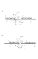
そこで、本実施の形態では、図6の(a)に示すように、先行シートS1の後端がニップ部95を通過する前に、食い込み量の切り替え動作、すなわち弾性ローラ94の矢印方向への移動動作を開始させるようにしている。これにより、先行シートS1の先端部分を、所定の食い込み量で、先端を含む押圧範囲Pを押圧した後、弾性ローラ94の矢印方向への移動動作が開始される。
Therefore, in the present embodiment, as shown in FIG. 6A, before the trailing end of the preceding sheet S1 passes through the
これにより、食い込み量の切り替え動作を行うための切り替え時間tを、ニップ部95を先端を含む押圧範囲Pの後端が通過してから、先行シート後端がニップ部95に達するまでの時間t1と、紙間t2とを合わせた時間とすることができる。つまり、食い込み量の切り替え動作を行うための切り替え時間tを、紙間t2よりも、ニップ部95を先端を含む押圧範囲Pの後端が通過してから、先行シート後端がニップ部95に達するまでの時間時間t1分長くすることができる。そして、このように切り替え時間tを長くすることにより、後続シートS2の先端がニップ部95に突入する前に切り替え動作を完了することができる。
As a result, the switching time t for performing the biting amount switching operation is the time t1 from when the rear end of the pressing range P including the leading end passes through the
なお、切り替え時間tはモータ能力に依存するため、シート種類に寄らず一定であるが、この切り替え時間tは可能な限り短くすることが望ましい。また、このようにシートの先端部に対してカールの補正を行うため、先行シート後端範囲と紙間とで食い込み量を切り替えるモードを先端押圧モードという。 Since the switching time t depends on the motor capacity and is constant regardless of the sheet type, it is desirable to make the switching time t as short as possible. In addition, a mode in which the amount of biting is switched between the trailing edge range of the preceding sheet and the space between the sheets in order to correct the curl with respect to the leading edge of the sheet is referred to as a leading edge pressing mode.
ところで、定着後に反転排紙、もしくは裏面画像形成を経て排紙されたシートは、定着直後とシート先後端が入れ替わっているため、反転した状態でニップ部95に達したとき、先行シート及び後続シートは、後端部分がカールした状態となっている。このため、この場合は、図6の(b)に示すように先行シートS1のシート後端を含む範囲Pを押圧した後、カールが生じていない後続シートS2の先端部分がニップ部95に達するまでに弾性ローラ94の矢印方向への移動動作を開始させるようにしている。
By the way, since the sheet discharged after reversal discharge or through backside image formation after fixing is switched between immediately after fixing and the front and rear ends of the sheet, when the sheet reaches the
これにより、食い込み量の切り替え動作を行うための切り替え時間tを、紙間t2と、後続シートS2の先端がニップ部95に達してから、押圧範囲Pの先端がニップ部95に達するまでの時間t3を合わせた時間とすることができる。つまり、食い込み量の切り替え動作を行うための切り替え時間tを、紙間t2よりも、後続シートS2の先端がニップ部95に達してから、押圧範囲Pの先端がニップ部95に達するまでの時間t3分長くすることができる。
Thus, the switching time t for performing the biting amount switching operation is the time from the paper interval t2 and the time when the leading edge of the succeeding sheet S2 reaches the
そして、このように切り替え時間tを長くすることにより、後続シートS2の押圧範囲Pの先端がニップ部95に突入する前に切り替え動作を完了することができる。なお、このように、シートの後端部に対してカールの補正を行うため、紙間と後続シートの押圧範囲Pの先端範囲で食い込み量を切り替えるモードを、後端押圧モードという。
In this way, by increasing the switching time t, the switching operation can be completed before the leading edge of the pressing range P of the succeeding sheet S2 enters the
図7は、このような押圧モードの切り替え動作を説明するフローチャートであり、CPU100は、入力部101により入力された排紙モード情報がストレート排紙かを判断する(S220)。そして、排紙モード情報がストレート排紙の場合は(S220のY)、図6の(a)に示す先端押圧モードによるカール補正を行う。また、排紙モード情報がストレート排紙でなく(S220のN)、反転排紙の場合は図6の(b)に示す後端押圧モードによるカール補正を行う。
FIG. 7 is a flowchart for explaining such a pressing mode switching operation. The
以上説明したように、本実施の形態においては、先行シートと後続シートの種類が異なる場合、カール補正量を、後続シートの種類に応じたカール補正量に変更する。そして、シートが、シート搬送方向下流側部分がカールしているシートの場合には、先行シートのシート搬送方向下流側部分がカール補正装置を通過してから後続シートがカール補正装置に達するまでにカール補正量の変更を終了するようにしている。また、シートが、シート搬送方向上流側部分がカールしているシートの場合には、先行シートがカール補正装置を通過してから後続シートのシート搬送方向上流側部分がカール補正装置に達するまでにカール補正部のカール補正量の変更を終了するようにしている。 As described above, in this embodiment, when the types of the preceding sheet and the subsequent sheet are different, the curl correction amount is changed to the curl correction amount according to the type of the subsequent sheet. If the sheet is a sheet with a curled downstream portion in the sheet conveying direction, the downstream portion of the preceding sheet in the sheet conveying direction passes through the curl correcting device and the subsequent sheet reaches the curl correcting device. The change of the curl correction amount is finished. If the sheet has a curl in the upstream side in the sheet conveyance direction, the upstream side of the subsequent sheet reaches the curl correction apparatus after the preceding sheet has passed the curl correction apparatus. The change of the curl correction amount of the curl correction unit is finished.
即ち、本実施の形態においては、先行シートと後続シートの種類が異なる場合、カール補正量の変更を開始するタイミングをシートのカール発生部分に応じて変更するようにしている。これにより、紙間が小さくなっても、1枚毎にそのシートに適切な食い込み量でカール補正を行うことが可能となり、この結果、種類の異なるシートに対しても確実にカールの補正を行うことができる。 That is, in the present embodiment, when the types of the preceding sheet and the succeeding sheet are different, the timing for starting the change of the curl correction amount is changed according to the curled portion of the sheet. This makes it possible to perform curl correction with an appropriate amount of biting into each sheet even when the gap between the sheets is reduced. As a result, it is possible to reliably correct curl even for different types of sheets. be able to.
また、経路情報によって切り替えタイミングを変更することにより、常に定着直後に先端になる側を含んだ範囲をカール補正することができるため、補正すべきカールを確実にかつ効率的に補正することが可能となる。この結果、生産性が高く、かつ混載を可能とする高機能画像形成装置においても、シートカールを確実かつ効率的に除去することが可能になる。なお、本実施の形態においては、カール補正装置3Aにカール補正部を2つ、すなわち複数配置したが、カール補正部は1つでも良く、またより確実にカールを補正するためには3つ以上設けても良い。
In addition, by changing the switching timing according to the route information, it is possible to always curl the range including the leading edge immediately after fixing, so that the curl to be corrected can be reliably and efficiently corrected. It becomes. As a result, the sheet curl can be reliably and efficiently removed even in a high-function image forming apparatus that is highly productive and can be mounted together. In the present embodiment, two curl correction units are arranged in the
1…カラーレーザプリンタ、1A…プリンタ本体(画像形成装置本体)、1B…画像形成部、1E…再搬送部、2…シート処理装置、3…バッファユニット、3A…カール補正装置、45…定着部、91…第1カール補正部、92…第2カール補正部、91a,92a…食い込み量調整部、93…固定ローラ、94…弾性ローラ、95(95a、95b)…ニップ部、100…CPU(演算制御部)、101…入力部、S1…先行シート、S2…後続シート、SN…経路センサ
DESCRIPTION OF
Claims (9)
前記定着部を通過したシートのカールを補正すると共に、カール補正量が可変なカール補正部と、
先行シートのためのカール補正量から後続シートのためのカール補正量に前記カール補正部のカール補正量を変更する際に、先行シートのシート搬送方向上流端が前記カール補正部を通過するまでに前記カール補正量の変更を開始して後続シートが前記カール補正部に達するまでに前記カール補正部のカール補正量の変更を終了するよう前記カール補正部を制御する制御部と、
を備えたことを特徴とする画像形成装置。 In an image forming apparatus, comprising: an image forming unit that forms a toner image; and a fixing unit that fixes the toner image to a sheet onto which the toner image is transferred, and sequentially forms images on different types of sheets.
While correcting the curl of the sheet that has passed through the fixing unit, a curl correction unit with a variable curl correction amount,
When the curl correction amount of the curl correction unit is changed from the curl correction amount for the preceding sheet to the curl correction amount for the subsequent sheet, the upstream end of the preceding sheet in the sheet conveyance direction passes through the curl correction unit. A control unit that controls the curl correction unit to end the change of the curl correction amount of the curl correction unit until the subsequent sheet reaches the curl correction unit after starting the change of the curl correction amount;
An image forming apparatus comprising:
前記定着部から前記カール補正部にシートを、シート搬送方向下流端及びシート搬送方向上流端が逆向きとなるように反転させて案内する反転搬送通路と、を備え、
前記制御部は、前記定着部を通過する際のシート搬送方向下流端が前記カール補正部を通過する際のシート搬送方向下流端となるようにシートが前記搬送通路を通過する場合は、前記第1モードを実行し、前記定着部を通過する際のシート搬送方向下流端が前記カール補正部を通過する際のシート搬送方向上流端となるようにシートが前記反転搬送通路を通過する場合は、前記第2モードを実行することを特徴とする請求項2記載の画像形成装置。 A conveyance path for guiding the sheet from the fixing unit to the curl correction unit;
A reversing conveyance path for reversing and guiding the sheet from the fixing unit to the curl correction unit so that the downstream end in the sheet conveyance direction and the upstream end in the sheet conveyance direction are opposite to each other, and
Wherein, when the as sheet conveying direction downstream end of the time of passing through the fixing portion is a sheet conveying direction downstream end of the time of passing through the curl correction unit sheet passes the conveying path, wherein the 1 run mode, when the as sheet conveying direction downstream end of the time of passing through the fixing unit becomes the sheet conveyance direction upstream end of the time of passing through the curl correction unit sheet passes through the reversing conveyance path, The image forming apparatus according to claim 2, wherein the second mode is executed .
前記定着部を通過したシートのカールを補正すると共に、カール補正量が可変なカール補正部と、
先行シートのためのカール補正量から後続シートのためのカール補正量に前記カール補正部のカール補正量を変更する際に、先行シートのシート搬送方向上流端が前記カール補正部を通過した後に、前記カール補正量の変更を開始し、且つ、前記後続シートの搬送方向下流端が前記カール補正部に達した後であって前記後続シートの搬送方向上流端が前記カール補正部を通過する前に前記カール補正部のカール補正量の変更を終了するよう前記カール補正部を制御する制御部と、
を備えたことを特徴とする画像形成装置。 In an image forming apparatus, comprising: an image forming unit that forms a toner image; and a fixing unit that fixes the toner image to a sheet onto which the toner image is transferred, and sequentially forms images on different types of sheets.
While correcting the curl of the sheet that has passed through the fixing unit, a curl correction unit with a variable curl correction amount,
When the curl correction amount of the curl correction unit is changed from the curl correction amount for the preceding sheet to the curl correction amount for the subsequent sheet, after the upstream end of the preceding sheet in the sheet conveyance direction passes through the curl correction unit, The change of the curl correction amount is started, and after the downstream end of the subsequent sheet in the conveyance direction reaches the curl correction unit and before the upstream end of the subsequent sheet in the conveyance direction passes through the curl correction unit. A control unit that controls the curl correction unit to finish changing the curl correction amount of the curl correction unit;
An image forming apparatus comprising:
前記制御部は、シートの種類に応じて前記湾曲したニップ部の湾曲量を調整するよう前記湾曲量調整部を制御することを特徴とする請求項1乃至6のいずれか1項に記載の画像形成装置。 The curl correction unit includes a curl correction roller pair including a pair of rollers having different hardnesses to form a nip portion curved by pressure contact, and a curve of the curved nip portion by changing a pressure contact pressure of the curl correction roller pair. A curving amount adjusting unit for adjusting the amount, and the sheet is passed through the curved nip portion of the curl correcting roller pair to correct the curling of the sheet,
7. The image according to claim 1, wherein the control unit controls the bending amount adjusting unit so as to adjust a bending amount of the curved nip portion according to a type of a sheet. Forming equipment.
前記制御部は、前記入力部から入力されたシート情報により先行シートと後続シートの種類が異なると判断した場合は、前記カール補正量を、先行シートの種類に応じた前記カール補正量から後続シートの種類に応じた前記カール補正量に変更するよう前記カール補正部を制御することを特徴とする請求項1乃至8のいずれか1項に記載の画像形成装置。 It has an input part to input the type of sheet,
When the control unit determines that the type of the preceding sheet and the succeeding sheet is different according to the sheet information input from the input unit, the curl correction amount is calculated from the curl correction amount according to the type of the preceding sheet. The image forming apparatus according to claim 1, wherein the curl correction unit is controlled to change the curl correction amount according to the type of the curl.
Priority Applications (2)
| Application Number | Priority Date | Filing Date | Title |
|---|---|---|---|
| JP2011265734A JP5911277B2 (en) | 2011-12-05 | 2011-12-05 | Image forming apparatus |
| US13/602,843 US8824954B2 (en) | 2011-12-05 | 2012-09-04 | Image forming apparatus |
Applications Claiming Priority (1)
| Application Number | Priority Date | Filing Date | Title |
|---|---|---|---|
| JP2011265734A JP5911277B2 (en) | 2011-12-05 | 2011-12-05 | Image forming apparatus |
Publications (3)
| Publication Number | Publication Date |
|---|---|
| JP2013116809A JP2013116809A (en) | 2013-06-13 |
| JP2013116809A5 JP2013116809A5 (en) | 2015-01-22 |
| JP5911277B2 true JP5911277B2 (en) | 2016-04-27 |
Family
ID=48524110
Family Applications (1)
| Application Number | Title | Priority Date | Filing Date |
|---|---|---|---|
| JP2011265734A Active JP5911277B2 (en) | 2011-12-05 | 2011-12-05 | Image forming apparatus |
Country Status (2)
| Country | Link |
|---|---|
| US (1) | US8824954B2 (en) |
| JP (1) | JP5911277B2 (en) |
Families Citing this family (5)
| Publication number | Priority date | Publication date | Assignee | Title |
|---|---|---|---|---|
| US9517906B2 (en) | 2012-08-29 | 2016-12-13 | Canon Kabushiki Kaisha | Conveying guide, sheet conveying apparatus, and image forming apparatus |
| JP6086103B2 (en) * | 2014-07-25 | 2017-03-01 | コニカミノルタ株式会社 | Image forming apparatus |
| JP6217689B2 (en) * | 2015-05-01 | 2017-10-25 | コニカミノルタ株式会社 | Paper humidifier and humidification control method |
| US11586130B2 (en) | 2021-02-25 | 2023-02-21 | Canon Kabushiki Kaisha | Image forming apparatus with guiding member fixed to guiding member to form feeding path of recording material |
| US11586131B2 (en) | 2021-02-25 | 2023-02-21 | Canon Kabushiki Kaisha | Image forming apparatus with guiding member configured to guide recording material and being fixed to holding member configured to hold roller |
Family Cites Families (16)
| Publication number | Priority date | Publication date | Assignee | Title |
|---|---|---|---|---|
| US5824408A (en) | 1995-04-28 | 1998-10-20 | Canon Kabushiki Kaisha | White electroconductive coating composition and transfer material-carrying member |
| US6023597A (en) | 1995-05-30 | 2000-02-08 | Canon Kabushiki Kaisha | Cellular conductive roller with conductive powder filling open cells in the surface |
| US5848347A (en) * | 1997-04-11 | 1998-12-08 | Xerox Corporation | Dual decurler and control mechanism therefor |
| US5920751A (en) * | 1998-01-08 | 1999-07-06 | Xerox Corporation | Apparatus and method for controlling moisture and cooling rate for paper curl reduction |
| JP2000227694A (en) * | 1999-02-08 | 2000-08-15 | Fuji Xerox Co Ltd | Image forming device |
| JP2000229758A (en) * | 1999-02-09 | 2000-08-22 | Fuji Xerox Co Ltd | Curl compensation device and picture image formation device |
| JP2003012215A (en) * | 2001-06-28 | 2003-01-15 | Konica Corp | Paper feeder, image formation apparatus and post- processing apparatus |
| JP2004315181A (en) * | 2003-04-17 | 2004-11-11 | Canon Inc | Uncurling device for image forming device |
| JP4065538B2 (en) * | 2003-09-22 | 2008-03-26 | キヤノン株式会社 | Curl correction device and image forming apparatus |
| JP4162004B2 (en) | 2005-12-13 | 2008-10-08 | コニカミノルタビジネステクノロジーズ株式会社 | Image forming apparatus, image forming method, and sheet material conveying apparatus |
| JP4883776B2 (en) * | 2006-08-23 | 2012-02-22 | キヤノン株式会社 | Recording device |
| JP5025350B2 (en) * | 2007-06-26 | 2012-09-12 | キヤノン株式会社 | Curl correction device and image forming apparatus |
| JP2010001089A (en) * | 2008-06-18 | 2010-01-07 | Konica Minolta Business Technologies Inc | Paper treatment device and image forming system |
| JP5262637B2 (en) * | 2008-12-02 | 2013-08-14 | 株式会社リコー | Curl correction device, image forming device, and sheet paper post-processing device |
| JP5404309B2 (en) * | 2009-10-27 | 2014-01-29 | キヤノン株式会社 | Method and apparatus for correcting curl of recording medium |
| US8862047B2 (en) * | 2010-03-25 | 2014-10-14 | Kyocera Document Solutions Inc. | Sheet curl correction apparatus and image forming apparatus |
-
2011
- 2011-12-05 JP JP2011265734A patent/JP5911277B2/en active Active
-
2012
- 2012-09-04 US US13/602,843 patent/US8824954B2/en active Active
Also Published As
| Publication number | Publication date |
|---|---|
| JP2013116809A (en) | 2013-06-13 |
| US20130142556A1 (en) | 2013-06-06 |
| US8824954B2 (en) | 2014-09-02 |
Similar Documents
| Publication | Publication Date | Title |
|---|---|---|
| JP6376810B2 (en) | Sheet conveying apparatus and image forming apparatus | |
| JP5963419B2 (en) | Image forming apparatus | |
| JP5893642B2 (en) | Skew correction device and image forming apparatus | |
| JP5197091B2 (en) | Sheet conveying apparatus and image forming apparatus | |
| JP5344602B2 (en) | Image forming apparatus | |
| JP5911277B2 (en) | Image forming apparatus | |
| US9671739B2 (en) | Sheet-conveying device that conveys sheets, and image-forming apparatus using the same | |
| JP2009196774A (en) | Sheet carrying device and image forming device | |
| US8002275B2 (en) | Sheet conveying apparatus and image forming apparatus having a first skew feeding correction unit and a second skew feeding correction unit | |
| JP5606486B2 (en) | Skew correction device and image forming apparatus | |
| JP5887951B2 (en) | Image forming apparatus | |
| US10183828B2 (en) | Sheet discharge device and image forming apparatus | |
| JP5980052B2 (en) | Sheet conveying apparatus and image forming apparatus | |
| JP5451818B2 (en) | Sheet conveying apparatus, image forming apparatus, and image reading apparatus | |
| JP2009113929A (en) | Sheet decurl device, image forming device and post-processing device | |
| JP2022029272A (en) | Sheet conveying device | |
| JP6776557B2 (en) | Image forming device | |
| JP6061560B2 (en) | Sheet conveying apparatus and image forming apparatus | |
| JP2017141092A (en) | Sheet conveyance device and image formation apparatus | |
| JP2017095210A (en) | Sheet transportation device, image formation system and control method | |
| JP5523617B2 (en) | Image forming apparatus | |
| JP6041560B2 (en) | Image forming apparatus | |
| JP2024003975A (en) | Image forming apparatus | |
| JP2013107713A (en) | Sheet conveying device, image forming apparatus, and image reading apparatus | |
| JP2005053607A (en) | Paper curl correction device and image forming device |
Legal Events
| Date | Code | Title | Description |
|---|---|---|---|
| A521 | Request for written amendment filed |
Free format text: JAPANESE INTERMEDIATE CODE: A523 Effective date: 20141203 |
|
| A621 | Written request for application examination |
Free format text: JAPANESE INTERMEDIATE CODE: A621 Effective date: 20141203 |
|
| A977 | Report on retrieval |
Free format text: JAPANESE INTERMEDIATE CODE: A971007 Effective date: 20150907 |
|
| A131 | Notification of reasons for refusal |
Free format text: JAPANESE INTERMEDIATE CODE: A131 Effective date: 20150915 |
|
| A521 | Request for written amendment filed |
Free format text: JAPANESE INTERMEDIATE CODE: A523 Effective date: 20151116 |
|
| TRDD | Decision of grant or rejection written | ||
| A01 | Written decision to grant a patent or to grant a registration (utility model) |
Free format text: JAPANESE INTERMEDIATE CODE: A01 Effective date: 20160301 |
|
| A61 | First payment of annual fees (during grant procedure) |
Free format text: JAPANESE INTERMEDIATE CODE: A61 Effective date: 20160329 |
|
| R151 | Written notification of patent or utility model registration |
Ref document number: 5911277 Country of ref document: JP Free format text: JAPANESE INTERMEDIATE CODE: R151 |