EP2258552A2 - Dispositif de détection d'un marquage sur un objet plat et procédé correspondant ainsi que dispositif destiné à la séparation de sections d'un objet plat - Google Patents
Dispositif de détection d'un marquage sur un objet plat et procédé correspondant ainsi que dispositif destiné à la séparation de sections d'un objet plat Download PDFInfo
- Publication number
- EP2258552A2 EP2258552A2 EP10005805A EP10005805A EP2258552A2 EP 2258552 A2 EP2258552 A2 EP 2258552A2 EP 10005805 A EP10005805 A EP 10005805A EP 10005805 A EP10005805 A EP 10005805A EP 2258552 A2 EP2258552 A2 EP 2258552A2
- Authority
- EP
- European Patent Office
- Prior art keywords
- mark
- marking
- sensor device
- marker
- detection
- Prior art date
- Legal status (The legal status is an assumption and is not a legal conclusion. Google has not performed a legal analysis and makes no representation as to the accuracy of the status listed.)
- Withdrawn
Links
- 238000000034 method Methods 0.000 title claims abstract description 40
- 238000001514 detection method Methods 0.000 claims abstract description 28
- 230000003287 optical effect Effects 0.000 claims abstract description 13
- 230000008569 process Effects 0.000 claims abstract description 11
- 238000007639 printing Methods 0.000 claims description 42
- 239000003550 marker Substances 0.000 claims description 18
- 238000005520 cutting process Methods 0.000 claims description 8
- 238000003384 imaging method Methods 0.000 claims description 4
- 230000001960 triggered effect Effects 0.000 claims description 4
- 238000011156 evaluation Methods 0.000 claims description 2
- 230000004044 response Effects 0.000 claims description 2
- 238000000926 separation method Methods 0.000 abstract description 4
- 238000005259 measurement Methods 0.000 description 7
- 239000000976 ink Substances 0.000 description 5
- 238000012545 processing Methods 0.000 description 5
- 230000033001 locomotion Effects 0.000 description 4
- 238000007689 inspection Methods 0.000 description 3
- 239000000123 paper Substances 0.000 description 3
- 230000008901 benefit Effects 0.000 description 2
- 238000004364 calculation method Methods 0.000 description 2
- 230000008859 change Effects 0.000 description 2
- 239000003086 colorant Substances 0.000 description 2
- 238000012937 correction Methods 0.000 description 2
- 230000001419 dependent effect Effects 0.000 description 2
- 230000006870 function Effects 0.000 description 2
- 239000000463 material Substances 0.000 description 2
- 230000009467 reduction Effects 0.000 description 2
- PLXMOAALOJOTIY-FPTXNFDTSA-N Aesculin Natural products OC[C@@H]1[C@@H](O)[C@H](O)[C@@H](O)[C@H](O)[C@H]1Oc2cc3C=CC(=O)Oc3cc2O PLXMOAALOJOTIY-FPTXNFDTSA-N 0.000 description 1
- 238000012935 Averaging Methods 0.000 description 1
- 230000001133 acceleration Effects 0.000 description 1
- 230000004075 alteration Effects 0.000 description 1
- 239000011111 cardboard Substances 0.000 description 1
- 230000003111 delayed effect Effects 0.000 description 1
- 238000011161 development Methods 0.000 description 1
- 230000018109 developmental process Effects 0.000 description 1
- 230000000694 effects Effects 0.000 description 1
- 238000013213 extrapolation Methods 0.000 description 1
- 230000002349 favourable effect Effects 0.000 description 1
- 238000005286 illumination Methods 0.000 description 1
- 239000007769 metal material Substances 0.000 description 1
- 238000007645 offset printing Methods 0.000 description 1
- 238000012634 optical imaging Methods 0.000 description 1
- 239000011087 paperboard Substances 0.000 description 1
- 238000011897 real-time detection Methods 0.000 description 1
- 238000001454 recorded image Methods 0.000 description 1
- 238000005070 sampling Methods 0.000 description 1
- 230000001360 synchronised effect Effects 0.000 description 1
- 238000012549 training Methods 0.000 description 1
Images
Classifications
-
- B—PERFORMING OPERATIONS; TRANSPORTING
- B41—PRINTING; LINING MACHINES; TYPEWRITERS; STAMPS
- B41F—PRINTING MACHINES OR PRESSES
- B41F13/00—Common details of rotary presses or machines
- B41F13/02—Conveying or guiding webs through presses or machines
-
- B—PERFORMING OPERATIONS; TRANSPORTING
- B26—HAND CUTTING TOOLS; CUTTING; SEVERING
- B26D—CUTTING; DETAILS COMMON TO MACHINES FOR PERFORATING, PUNCHING, CUTTING-OUT, STAMPING-OUT OR SEVERING
- B26D5/00—Arrangements for operating and controlling machines or devices for cutting, cutting-out, stamping-out, punching, perforating, or severing by means other than cutting
- B26D5/007—Control means comprising cameras, vision or image processing systems
-
- B—PERFORMING OPERATIONS; TRANSPORTING
- B26—HAND CUTTING TOOLS; CUTTING; SEVERING
- B26D—CUTTING; DETAILS COMMON TO MACHINES FOR PERFORATING, PUNCHING, CUTTING-OUT, STAMPING-OUT OR SEVERING
- B26D5/00—Arrangements for operating and controlling machines or devices for cutting, cutting-out, stamping-out, punching, perforating, or severing by means other than cutting
- B26D5/20—Arrangements for operating and controlling machines or devices for cutting, cutting-out, stamping-out, punching, perforating, or severing by means other than cutting with interrelated action between the cutting member and work feed
- B26D5/30—Arrangements for operating and controlling machines or devices for cutting, cutting-out, stamping-out, punching, perforating, or severing by means other than cutting with interrelated action between the cutting member and work feed having the cutting member controlled by scanning a record carrier
- B26D5/32—Arrangements for operating and controlling machines or devices for cutting, cutting-out, stamping-out, punching, perforating, or severing by means other than cutting with interrelated action between the cutting member and work feed having the cutting member controlled by scanning a record carrier with the record carrier formed by the work itself
-
- B—PERFORMING OPERATIONS; TRANSPORTING
- B26—HAND CUTTING TOOLS; CUTTING; SEVERING
- B26D—CUTTING; DETAILS COMMON TO MACHINES FOR PERFORATING, PUNCHING, CUTTING-OUT, STAMPING-OUT OR SEVERING
- B26D5/00—Arrangements for operating and controlling machines or devices for cutting, cutting-out, stamping-out, punching, perforating, or severing by means other than cutting
- B26D5/20—Arrangements for operating and controlling machines or devices for cutting, cutting-out, stamping-out, punching, perforating, or severing by means other than cutting with interrelated action between the cutting member and work feed
- B26D5/30—Arrangements for operating and controlling machines or devices for cutting, cutting-out, stamping-out, punching, perforating, or severing by means other than cutting with interrelated action between the cutting member and work feed having the cutting member controlled by scanning a record carrier
- B26D5/34—Arrangements for operating and controlling machines or devices for cutting, cutting-out, stamping-out, punching, perforating, or severing by means other than cutting with interrelated action between the cutting member and work feed having the cutting member controlled by scanning a record carrier scanning being effected by a photosensitive device
-
- B—PERFORMING OPERATIONS; TRANSPORTING
- B41—PRINTING; LINING MACHINES; TYPEWRITERS; STAMPS
- B41F—PRINTING MACHINES OR PRESSES
- B41F13/00—Common details of rotary presses or machines
- B41F13/54—Auxiliary folding, cutting, collecting or depositing of sheets or webs
- B41F13/56—Folding or cutting
- B41F13/60—Folding or cutting crosswise
-
- B—PERFORMING OPERATIONS; TRANSPORTING
- B41—PRINTING; LINING MACHINES; TYPEWRITERS; STAMPS
- B41F—PRINTING MACHINES OR PRESSES
- B41F33/00—Indicating, counting, warning, control or safety devices
- B41F33/0081—Devices for scanning register marks
-
- B—PERFORMING OPERATIONS; TRANSPORTING
- B65—CONVEYING; PACKING; STORING; HANDLING THIN OR FILAMENTARY MATERIAL
- B65H—HANDLING THIN OR FILAMENTARY MATERIAL, e.g. SHEETS, WEBS, CABLES
- B65H23/00—Registering, tensioning, smoothing or guiding webs
- B65H23/04—Registering, tensioning, smoothing or guiding webs longitudinally
- B65H23/18—Registering, tensioning, smoothing or guiding webs longitudinally by controlling or regulating the web-advancing mechanism, e.g. mechanism acting on the running web
- B65H23/188—Registering, tensioning, smoothing or guiding webs longitudinally by controlling or regulating the web-advancing mechanism, e.g. mechanism acting on the running web in connection with running-web
- B65H23/1882—Registering, tensioning, smoothing or guiding webs longitudinally by controlling or regulating the web-advancing mechanism, e.g. mechanism acting on the running web in connection with running-web and controlling longitudinal register of web
-
- G—PHYSICS
- G01—MEASURING; TESTING
- G01P—MEASURING LINEAR OR ANGULAR SPEED, ACCELERATION, DECELERATION, OR SHOCK; INDICATING PRESENCE, ABSENCE, OR DIRECTION, OF MOVEMENT
- G01P3/00—Measuring linear or angular speed; Measuring differences of linear or angular speeds
- G01P3/64—Devices characterised by the determination of the time taken to traverse a fixed distance
- G01P3/68—Devices characterised by the determination of the time taken to traverse a fixed distance using optical means, i.e. using infrared, visible, or ultraviolet light
-
- B—PERFORMING OPERATIONS; TRANSPORTING
- B65—CONVEYING; PACKING; STORING; HANDLING THIN OR FILAMENTARY MATERIAL
- B65H—HANDLING THIN OR FILAMENTARY MATERIAL, e.g. SHEETS, WEBS, CABLES
- B65H2301/00—Handling processes for sheets or webs
- B65H2301/50—Auxiliary process performed during handling process
- B65H2301/51—Modifying a characteristic of handled material
- B65H2301/515—Cutting handled material
- B65H2301/5151—Cutting handled material transversally to feeding direction
Definitions
- the invention relates to a device for detecting a marking provided on a flat article, such as a printing web or other sheet-like printed products, typically made of paper or cardboard, and a method for detecting a corresponding marking, as well as a device for separating sections of one such object.
- a method for determining Passerdifferenzen has become known, wherein a print image location is increased with expected Passerdifferenzen of a color video camera is detected and a determination of Passerdifferenzen by a determination of layers of the different colored sub-images to each other.
- the optical signal of the color video camera is color-separated according to the printing inks used in printing. A contour resulting from overprinting of at least two printing inks can therefore be accommodated in two representations of the at least two printing inks.
- a registration difference can be calculated and taken into account in subsequent printing processes. That in the DE 40 12 608 A1 described method requires a complex calculation with complex optics.
- the invention is therefore based on the object to get along with processing operations in the flat, such as curved objects such as printing lines or printed products position determinations without an additional application of the printing or the appearance of the arcuate object disturbing markings.
- the invention provides a method for detecting at least one provided on a flat article, in particular a printing or printed product mark in which the mark is imaged by means of an optical element on a sensor device and the sensor device is an image of the at least one mark with respect Recorded characteristic.
- a word and / or picture information present on the object is used as at least one mark.
- the detection of the at least one marking is recorded as a function of a comparison of a reference, determined by the sensor device before the detection process with respect to the characteristic, of the at least one marking with that of the sensor device verified at least one mark with respect to the characteristic.
- a device for detecting at least one marking provided on a flat object, in particular a printing web or more generally a printed product, the device comprising an optical element for imaging the at least one marking on a sensor device and the sensor device for recording the at least one illustrated image Mark is formed in terms of a characteristic.
- the device is characterized in that the at least one marking is a word and / or image information present on the article and that it contains a comparator unit assigned to the sensor device, in which a reference of the at least one marking can be stored with regard to its parameter.
- the comparator device is designed to verify the detection of the at least one marking via an evaluation of a comparison of the stored marking with the at least one marking with regard to the parameter recorded by the sensor device.
- the invention further provides a device for separating sections of such a flat object, in particular a printing web or generally a printed product along predeterminable markings, which device comprises a device for detecting at least one marking provided on the article.
- a mark determined in advance by a system also to be used during the actual position detection is used as a reference in a memory device. or comparator medium. This is accessed in a real-time in a comparison method to be performed at a time in a very short period of time marker detection. Depending on the comparison result between the at least one marker recorded in real time and the reference stored in advance, the actual detection of the at least one marker can be verified.
- an absolute position of the flat article can be determined according to the invention. This is done by knowing the distance of the at least one mark from edges of the object. With the aid of a knowledge of the relative distances between several markings and the absolute detection position, a dimensional measurement of the object can be made.
- the invention has the advantage of a large variability while avoiding additional expenditure on equipment with it.
- a reference of the at least one marking of the sensor device can be supplied in each case before the detection process and then compared with the at least one marking with respect to the characteristic recorded by the sensor device.
- the reference can also be measured periodically or it is possible to resort to stored references.
- a characteristic of the at least one mark is a brightness contrast that can be recorded by the sensor device. The presence of the at least one marking or its detection can, however, also be detected or carried out on the basis of a color contrast in one or more colors.
- extended markings are well suited as marking in the sense of the invention.
- Particularly advantageous is the use of an outline or edge of an attached on the sheet object marking as used for positioning or position determination mark.
- a middle region of the contour line or edge can be irradiated with light particularly advantageously and imaged onto the sensor device. Changes in color and / or brightness contrast are usually sufficiently strong here.
- the position-indicating marking can be a head and / or footprint line applied to at least one section of the flat article.
- the position-indicating marking in the context of the invention, inter alia, as a printing or printed product made of paper, plastic or similar, transportable via rollers materials or sheet-like bodies such as elastic films about metal materials or elastic plates, these are in known decency of edges appropriate. This is especially the case with letterheads, envelopes or other printed matter.
- a threshold value of the parameter is predetermined, the detection of which detects the presence of the at least one marking. This is done in a reference detection of the marking, in which the sensor device and the comparator unit or the other optical imaging devices are set to the mark to be used or even optimized.
- the effects of stray and / or extraneous light can be taken into account immediately and thus further increase the accuracy of the real-time detection.
- the threshold value that determines the presence of a marker is set in a middle region of the at least one marker and read in advance accordingly at a reference marker. Even in the case of a blurred optical image of the mark on the detectable by the sensor device, preferably line-like position, the threshold value is still sufficiently well and discrete detectable. This also applies in pixel scale.
- a distance of the at least one mark from the desired position by means of the sensor device or another sensor device recorded at least two times of a movement process of the sheet, such as arcuate object so according to the invention a marking speed or corresponding arrival time of the mark on the Target position to be determined.
- a calculation can be based on a movement at constant speed.
- measurement at three positions is advantageous.
- the velocity determination gives redundancy to the method according to the invention.
- For both from the mark detection or detection at the desired position and from the speed determination of the sheet object can be accurately fed to a further processing such as another printing, a cutting process or a removal from the device. In case of failure or presence of an error in one of the positioning variants, the remaining one alone is still sufficient.
- the achievement of a desired position of the marking or of a point spaced apart from the marking along the feed direction can be effected in an exact manner, including the speed. Achieving the desired position can also be done after the last measurement. In this case, based on the determined speed and at least one position determined at a certain point in time, an extrapolation of the time at which the setpoint position is reached takes place. When this time is reached, a switching signal can be output to trigger a particular event, in particular the operation of a cutting device.
- the device is set up correspondingly to detect positions of a marking several times in succession and comprises a computing device which is set up to calculate a point in time at which the marking or a point spaced from the marking along the feed direction at a defined distance reaches a target position, the device having a switching output at which a switching signal is output in response to the target position being reached.
- a cutting tool in particular a cutting tool can be triggered, which separates the object at a defined position with respect to the position of the marker.
- a plurality of markings having different threshold values can preferably be detected on a flat article or on a printing web. This offers particular advantages when working with different resolutions. Thus, with different accuracy resolvable markers can be selected.
- the size of the measuring fields can be set as different as the mark can be selected in terms of their resolution.
- a mark detection can then also be carried out with variable threshold values.
- the light source according to the invention find light-emitting diodes, LEDs, use.
- the optical sensor devices are to be adapted to the LEDs to be used in color and intensity.
- Inventive sampling or measuring frequencies are in the range up to several tens of MHz.
- the exposure time per image is less than 50 microseconds.
- the components used in the device according to the invention are chosen so that a high degree of miniaturization and thus a small space requirement can be achieved. With the short measurement distances achievable in this way, an influence of stray or extraneous light is sufficiently reduced.
- the influence can be additionally reduced by using a pulsed illumination that is synchronized with the shutter of the camera by means of a synchronization device.
- the pulse duration is less than the above-mentioned 50 microseconds.
- a dark measurement ie an image recording can be performed with the lighting off, to determine the residual light component.
- the residual light component can then be advantageously subtracted from the images taken during the recognition process.
- the image refresh rate is preferably at least 500 Hz.
- a small sensor with at most 500 pixels in the direction transverse to the feed direction can be used.
- line sensors can also be used, the image information being composed of successively recorded image lines.
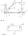
- FIG. 1a To FIG. 1a is moved in a generally designated by the reference numeral 1 inventive device for detecting at least one mark of a printing run 2 made of paper flat object on a transport system 3 in the direction of arrow a with respect to a light source 4 and a position sensor 5.
- a collimator lens 6 From the light source 4 to Fig. 1a at a 90 degree angle by means of a collimator lens 6 to a region of the printing web 2 irradiated light beams 7 are in the range of a polychrome or otherwise optically contrasting Mark 8 partially reflected.
- a further arranged at an angle of 45 degrees relative to the incident light beam 7 converging lens 10 is provided for imaging of the beam 8 partially reflected by the beam 8 on the position sensor 5.
- the position sensor detects an area which is also extended along the feed direction. As long as the light beam 9 shown on the position sensor 5 has no intensity or other changes, the feed of the printing web 2 continues unchanged.
- the position of the mark can be determined in particular also several times. Based on the time interval can thus be determined with respect to the position sensor, the speed of the marker 8, wherein in the case of at least three measurements and an accelerated movement can be detected. If the speed is known, the device according to the invention can calculate the point in time at which the marking or a point spaced from the marking at a defined distance along the running or advancing direction arrives at a desired position.
- the printing web can be cut, for example by means of a cutting device into individual sheets.
- mark 8a which is illustrated by way of example, the position sensor 5 records a change in intensity.
- the presence of a marking 8 is detected by the memory or comparator unit 11 assigned to the position sensor 5 on the basis of the resulting change in intensity.
- a reference print web 2r with the transport system 3 in the in Fig. 1a shown manner at the light source 4 and the Position sensor 5 passes, wherein the position sensor 5 has received the caused by the mark 8r intensity changes.
- the previously recorded intensity changes are in the storage sensor 5 associated memory or
- Comparator 11 stored.
- the degree of intensity "used for training" which serves to identify the marking 8 can be stored sufficiently precisely.
- Such a cutting or separating process in which the printing web 8 is subdivided into sections 22, is in an application of a device according to the invention in Fig. 1c illustrated schematically.
- a device 20 which can be used in an inserting method. be supplied to the paper webs 23 and 24 via respective transport rollers 25a, 25b, 26a, 26b in the direction of arrow a of a separator 27.
- a separation process is initiated by the separator 27.
- the markers 81 and 82 are shown with roughly simplified and those of Fig. 1a corresponding optical position detecting means 51, 52 detected.
- the optical position detecting means 51 and 52 detect an intensity difference of an optical scanning signal caused by the marks 81 and 82, a control signal is output to the separating device 27 so as to sever the printing lines 23, 24 at a separation point 28.
- a control signal is output to the separating device 27 so as to sever the printing lines 23, 24 at a separation point 28.
- Fig. 1b In an application of the method according to the invention or a device according to the invention for separating printing webs along predetermined dividing lines into sections, the simplified in Fig. 1b shown manner different pages of letters, invoices or leaflets fed to an inserting machine and stored in this exact position and subjected to further processing in the form of an introduction of a fold.
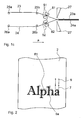
- a detection of a mark can be determined on the basis of a predetermined (learned) threshold value.
- a threshold will be at an extended mark such as in Fig. 2 set in the center of the mark 8a to minimize aberrations caused by the imaging optics used in the present invention. This is after Fig. 2 the threshold value of the outline portion 8u of the mark 8a is used.
Landscapes
- Engineering & Computer Science (AREA)
- Mechanical Engineering (AREA)
- Life Sciences & Earth Sciences (AREA)
- Forests & Forestry (AREA)
- Physics & Mathematics (AREA)
- General Physics & Mathematics (AREA)
- Computer Vision & Pattern Recognition (AREA)
- Controlling Sheets Or Webs (AREA)
- Inking, Control Or Cleaning Of Printing Machines (AREA)
- Handling Of Sheets (AREA)
Applications Claiming Priority (1)
| Application Number | Priority Date | Filing Date | Title |
|---|---|---|---|
| DE200910023948 DE102009023948B4 (de) | 2009-06-04 | 2009-06-04 | Vorrichtung zum Erfassen einer Markierung auf einem flächigen Gegenstand und Verfahren dazu sowie Einrichtung zum Trennen von Abschnitten von einem flächigen Gegenstand |
Publications (3)
| Publication Number | Publication Date |
|---|---|
| EP2258552A2 true EP2258552A2 (fr) | 2010-12-08 |
| EP2258552A8 EP2258552A8 (fr) | 2011-04-06 |
| EP2258552A3 EP2258552A3 (fr) | 2012-09-26 |
Family
ID=42668094
Family Applications (1)
| Application Number | Title | Priority Date | Filing Date |
|---|---|---|---|
| EP10005805A Withdrawn EP2258552A3 (fr) | 2009-06-04 | 2010-06-04 | Dispositif de détection d'un marquage sur un objet plat et procédé correspondant ainsi que dispositif destiné à la séparation de sections d'un objet plat |
Country Status (2)
| Country | Link |
|---|---|
| EP (1) | EP2258552A3 (fr) |
| DE (1) | DE102009023948B4 (fr) |
Cited By (3)
| Publication number | Priority date | Publication date | Assignee | Title |
|---|---|---|---|---|
| EP2481585A1 (fr) * | 2011-01-28 | 2012-08-01 | Müller Martini Holding AG | Dispositif et procédé de traitement d'une bande de matière d'impression pour produits d'impression |
| CN102673113A (zh) * | 2012-05-08 | 2012-09-19 | 深圳劲嘉彩印集团股份有限公司 | 单张纸烫金、模切设备电子定位装置及方法 |
| DE102016118548A1 (de) | 2016-09-29 | 2018-03-29 | Packsys Global Ag | Verfahren und Vorrichtung zum beidseitigen Besäumen eines Flachmaterials im Rahmen der Tubenherstellung |
Families Citing this family (1)
| Publication number | Priority date | Publication date | Assignee | Title |
|---|---|---|---|---|
| US20150090140A1 (en) | 2013-10-01 | 2015-04-02 | Goss International Americas Inc. | Print job and process roll event tracking |
Citations (5)
| Publication number | Priority date | Publication date | Assignee | Title |
|---|---|---|---|---|
| DE4012608A1 (de) | 1990-04-20 | 1991-10-24 | Roland Man Druckmasch | Verfahren und vorrichtung zur bestimmung von passerdifferenzen an druckbildstellen eines mehrfarbenoffsetdruckes |
| DE19517842A1 (de) | 1995-05-18 | 1996-11-21 | Saechsisches Inst Fuer Die Dru | Verfahren zur Messung von Meßmarken |
| DE10250592A1 (de) | 2002-10-30 | 2004-05-19 | Bst International Gmbh | Verfahren und Vorrichtung zum Erfassen von Druckmarken auf einer bewegten Druckbahn |
| US20050254067A1 (en) | 2004-05-11 | 2005-11-17 | Martin Gaon | Apparatus and methods for high speed rgb color discrimination |
| EP1808680A2 (fr) | 2006-01-11 | 2007-07-18 | Omron Corporation | Procédé et appareil de mesure utilisant des images couleurs |
Family Cites Families (4)
| Publication number | Priority date | Publication date | Assignee | Title |
|---|---|---|---|---|
| DE10049752A1 (de) * | 1999-10-11 | 2001-05-10 | Heidelberger Druckmasch Ag | Verfahren zur Erkennung der Lagegenauigkeit von Register und Falz-oder Schneidkanten an flachen Exemplaren |
| DE102004028056A1 (de) * | 2004-04-22 | 2005-11-17 | Maschinenfabrik Wifag | Vorrichtung und Verfahren zur Erkennung von Registerfehlern |
| DE102004052450A1 (de) * | 2004-10-28 | 2006-05-04 | Sick Ag | Sensor |
| JP4891608B2 (ja) * | 2005-12-19 | 2012-03-07 | 三菱重工印刷紙工機械株式会社 | 印刷機の断裁制御装置及び断裁制御方法 |
-
2009
- 2009-06-04 DE DE200910023948 patent/DE102009023948B4/de not_active Expired - Fee Related
-
2010
- 2010-06-04 EP EP10005805A patent/EP2258552A3/fr not_active Withdrawn
Patent Citations (6)
| Publication number | Priority date | Publication date | Assignee | Title |
|---|---|---|---|---|
| DE4012608A1 (de) | 1990-04-20 | 1991-10-24 | Roland Man Druckmasch | Verfahren und vorrichtung zur bestimmung von passerdifferenzen an druckbildstellen eines mehrfarbenoffsetdruckes |
| DE19517842A1 (de) | 1995-05-18 | 1996-11-21 | Saechsisches Inst Fuer Die Dru | Verfahren zur Messung von Meßmarken |
| DE10250592A1 (de) | 2002-10-30 | 2004-05-19 | Bst International Gmbh | Verfahren und Vorrichtung zum Erfassen von Druckmarken auf einer bewegten Druckbahn |
| US20050254067A1 (en) | 2004-05-11 | 2005-11-17 | Martin Gaon | Apparatus and methods for high speed rgb color discrimination |
| US7365854B2 (en) | 2004-05-11 | 2008-04-29 | Nordson Corporation | Apparatus and methods for high speed RGB color discrimination |
| EP1808680A2 (fr) | 2006-01-11 | 2007-07-18 | Omron Corporation | Procédé et appareil de mesure utilisant des images couleurs |
Cited By (4)
| Publication number | Priority date | Publication date | Assignee | Title |
|---|---|---|---|---|
| EP2481585A1 (fr) * | 2011-01-28 | 2012-08-01 | Müller Martini Holding AG | Dispositif et procédé de traitement d'une bande de matière d'impression pour produits d'impression |
| CN102673113A (zh) * | 2012-05-08 | 2012-09-19 | 深圳劲嘉彩印集团股份有限公司 | 单张纸烫金、模切设备电子定位装置及方法 |
| CN102673113B (zh) * | 2012-05-08 | 2014-12-17 | 深圳劲嘉彩印集团股份有限公司 | 单张纸烫金、模切设备电子定位装置及方法 |
| DE102016118548A1 (de) | 2016-09-29 | 2018-03-29 | Packsys Global Ag | Verfahren und Vorrichtung zum beidseitigen Besäumen eines Flachmaterials im Rahmen der Tubenherstellung |
Also Published As
| Publication number | Publication date |
|---|---|
| EP2258552A8 (fr) | 2011-04-06 |
| EP2258552A3 (fr) | 2012-09-26 |
| DE102009023948B4 (de) | 2013-05-29 |
| DE102009023948A1 (de) | 2010-12-16 |
Similar Documents
| Publication | Publication Date | Title |
|---|---|---|
| EP0884179B1 (fr) | Procédé de regulation des operations effectuées par une machine d'impression | |
| EP1454746B1 (fr) | Système d'inspection d'images pour une machine d'impression | |
| EP1714786B1 (fr) | Dispositif pour l'inspection de produits imprimés | |
| EP2481585B1 (fr) | Dispositif et procédé de traitement d'une bande de matière d'impression pour produits d'impression | |
| DE10214531A1 (de) | Verfahren und Einrichtung zur Messung von Positionen von durchlaufenden Bogen | |
| DE3830732A1 (de) | Verfahren zur ueberwachung und/oder regelung der feuchtmittelfuehrung bei einer offset-druckmaschine | |
| EP2943340B1 (fr) | Procédé permettant de fabriquer une bande de papier sans fin | |
| EP1785276B1 (fr) | Système de contrôle de la qualité pour une machine à imprimer | |
| DE102007030571B4 (de) | Farbmessvorrichtung mit zwei unterschiedlich arbeitenden Messeinrichtungen | |
| DE102009023948B4 (de) | Vorrichtung zum Erfassen einer Markierung auf einem flächigen Gegenstand und Verfahren dazu sowie Einrichtung zum Trennen von Abschnitten von einem flächigen Gegenstand | |
| AT501210B1 (de) | Verfahren zur qualitätskontrolle an oberflächenvariablen drucksachen | |
| DE102004028056A1 (de) | Vorrichtung und Verfahren zur Erkennung von Registerfehlern | |
| EP1403045A2 (fr) | Procédé et dispositif pour déterminer la position et/ou la forme de marques de repérage sur une bande de papier imprimée | |
| WO2019219727A1 (fr) | Procédé destiné à inspecter des récipients par détermination de position | |
| EP1752292A2 (fr) | Système pour contrôler la qualité d'une machine à imprimer | |
| DE102008012588A1 (de) | Verfahren und Vorrichtung zum Messen der Farbdichte eines Farbbalkens in einer Druckmaschine, und Druckmaschine, die mit einer Farbdichte-Messvorrichtung ausgestattet ist | |
| EP1980516B1 (fr) | Procédé de mesure et dispositif de détermination de la position de bandes de matériau | |
| DE10303282B4 (de) | Verfahren zur Inline-Qualitätsprüfung und zum Authentizitätsnachweis von bedruckten und/oder geprägten bahnförmigen Materialien | |
| DE102007041673A1 (de) | Verfahren und Messeinrichtung zur Gewinnung von Druckbild- oder Druckplatteninformationen | |
| DE2153972A1 (de) | Registerregelverfahren fuer endlospapierbahnen | |
| DE19840301A1 (de) | Verfahren zum Druck von Darstellungen auf beiden Seiten eines Trägermaterials | |
| DE102022115809B3 (de) | Verfahren zum Betreiben einer Tintenstrahldruckmaschine mit einer Auswahlgeschwindigkeit und/oder einer Auswahltaktfrequenz | |
| DE10332879A1 (de) | Verfahren zum Steuern einer Sensoreinrichtung und Sensoreinrichtung für eine Druckmaschine | |
| EP2017082B1 (fr) | Méthode pour déterminer des rapports sur une bande | |
| DE102019106549B4 (de) | Verfahren zur Ermittlung einer Abweichung einer Positionierung zumindest eines Druckkopfes eines zweiten Düsenbalkens relativ zu zumindest einem Druckkopf eines ersten Düsenbalkens einer Druckmaschine |
Legal Events
| Date | Code | Title | Description |
|---|---|---|---|
| PUAI | Public reference made under article 153(3) epc to a published international application that has entered the european phase |
Free format text: ORIGINAL CODE: 0009012 |
|
| AK | Designated contracting states |
Kind code of ref document: A2 Designated state(s): AL AT BE BG CH CY CZ DE DK EE ES FI FR GB GR HR HU IE IS IT LI LT LU LV MC MK MT NL NO PL PT RO SE SI SK SM TR |
|
| AX | Request for extension of the european patent |
Extension state: BA ME RS |
|
| RIN1 | Information on inventor provided before grant (corrected) |
Inventor name: KLUSER, CHRISTOPH Inventor name: FURRER, BERNHARD Inventor name: TIEDEKE, JOACHIM Inventor name: MUELLER, KLAUS FRIEDRICH, DR. |
|
| PUAL | Search report despatched |
Free format text: ORIGINAL CODE: 0009013 |
|
| AK | Designated contracting states |
Kind code of ref document: A3 Designated state(s): AL AT BE BG CH CY CZ DE DK EE ES FI FR GB GR HR HU IE IS IT LI LT LU LV MC MK MT NL NO PL PT RO SE SI SK SM TR |
|
| AX | Request for extension of the european patent |
Extension state: BA ME RS |
|
| RIC1 | Information provided on ipc code assigned before grant |
Ipc: B26D 5/00 20060101ALI20120820BHEP Ipc: G01N 35/00 20060101ALI20120820BHEP Ipc: B65H 23/188 20060101ALI20120820BHEP Ipc: B26D 5/32 20060101ALI20120820BHEP Ipc: B41F 33/00 20060101ALI20120820BHEP Ipc: G01P 3/68 20060101ALI20120820BHEP Ipc: B26D 5/34 20060101ALI20120820BHEP Ipc: B41F 13/02 20060101AFI20120820BHEP Ipc: B41F 33/14 20060101ALI20120820BHEP Ipc: B41F 13/60 20060101ALI20120820BHEP |
|
| STAA | Information on the status of an ep patent application or granted ep patent |
Free format text: STATUS: THE APPLICATION IS DEEMED TO BE WITHDRAWN |
|
| 18D | Application deemed to be withdrawn |
Effective date: 20130327 |