EP2257734B1 - Optische anordnung für leuchte mit punktförmiger lichtquelle und asymmetrischer lichtabstrahlcharakteristik - Google Patents
Optische anordnung für leuchte mit punktförmiger lichtquelle und asymmetrischer lichtabstrahlcharakteristik Download PDFInfo
- Publication number
- EP2257734B1 EP2257734B1 EP09727429.4A EP09727429A EP2257734B1 EP 2257734 B1 EP2257734 B1 EP 2257734B1 EP 09727429 A EP09727429 A EP 09727429A EP 2257734 B1 EP2257734 B1 EP 2257734B1
- Authority
- EP
- European Patent Office
- Prior art keywords
- light source
- light
- luminaire according
- lamp
- luminaire
- Prior art date
- Legal status (The legal status is an assumption and is not a legal conclusion. Google has not performed a legal analysis and makes no representation as to the accuracy of the status listed.)
- Not-in-force
Links
Images

Classifications
-
- G—PHYSICS
- G02—OPTICS
- G02B—OPTICAL ELEMENTS, SYSTEMS OR APPARATUS
- G02B27/00—Optical systems or apparatus not provided for by any of the groups G02B1/00 - G02B26/00, G02B30/00
- G02B27/09—Beam shaping, e.g. changing the cross-sectional area, not otherwise provided for
- G02B27/0938—Using specific optical elements
- G02B27/095—Refractive optical elements
- G02B27/0955—Lenses
-
- F—MECHANICAL ENGINEERING; LIGHTING; HEATING; WEAPONS; BLASTING
- F21—LIGHTING
- F21V—FUNCTIONAL FEATURES OR DETAILS OF LIGHTING DEVICES OR SYSTEMS THEREOF; STRUCTURAL COMBINATIONS OF LIGHTING DEVICES WITH OTHER ARTICLES, NOT OTHERWISE PROVIDED FOR
- F21V13/00—Producing particular characteristics or distribution of the light emitted by means of a combination of elements specified in two or more of main groups F21V1/00 - F21V11/00
- F21V13/02—Combinations of only two kinds of elements
- F21V13/04—Combinations of only two kinds of elements the elements being reflectors and refractors
-
- F—MECHANICAL ENGINEERING; LIGHTING; HEATING; WEAPONS; BLASTING
- F21—LIGHTING
- F21V—FUNCTIONAL FEATURES OR DETAILS OF LIGHTING DEVICES OR SYSTEMS THEREOF; STRUCTURAL COMBINATIONS OF LIGHTING DEVICES WITH OTHER ARTICLES, NOT OTHERWISE PROVIDED FOR
- F21V5/00—Refractors for light sources
- F21V5/04—Refractors for light sources of lens shape
-
- F—MECHANICAL ENGINEERING; LIGHTING; HEATING; WEAPONS; BLASTING
- F21—LIGHTING
- F21V—FUNCTIONAL FEATURES OR DETAILS OF LIGHTING DEVICES OR SYSTEMS THEREOF; STRUCTURAL COMBINATIONS OF LIGHTING DEVICES WITH OTHER ARTICLES, NOT OTHERWISE PROVIDED FOR
- F21V7/00—Reflectors for light sources
- F21V7/0066—Reflectors for light sources specially adapted to cooperate with point like light sources; specially adapted to cooperate with light sources the shape of which is unspecified
-
- F—MECHANICAL ENGINEERING; LIGHTING; HEATING; WEAPONS; BLASTING
- F21—LIGHTING
- F21V—FUNCTIONAL FEATURES OR DETAILS OF LIGHTING DEVICES OR SYSTEMS THEREOF; STRUCTURAL COMBINATIONS OF LIGHTING DEVICES WITH OTHER ARTICLES, NOT OTHERWISE PROVIDED FOR
- F21V7/00—Reflectors for light sources
- F21V7/04—Optical design
- F21V7/09—Optical design with a combination of different curvatures
-
- G—PHYSICS
- G02—OPTICS
- G02B—OPTICAL ELEMENTS, SYSTEMS OR APPARATUS
- G02B19/00—Condensers, e.g. light collectors or similar non-imaging optics
- G02B19/0004—Condensers, e.g. light collectors or similar non-imaging optics characterised by the optical means employed
- G02B19/0028—Condensers, e.g. light collectors or similar non-imaging optics characterised by the optical means employed refractive and reflective surfaces, e.g. non-imaging catadioptric systems
-
- G—PHYSICS
- G02—OPTICS
- G02B—OPTICAL ELEMENTS, SYSTEMS OR APPARATUS
- G02B19/00—Condensers, e.g. light collectors or similar non-imaging optics
- G02B19/0033—Condensers, e.g. light collectors or similar non-imaging optics characterised by the use
- G02B19/0047—Condensers, e.g. light collectors or similar non-imaging optics characterised by the use for use with a light source
- G02B19/0061—Condensers, e.g. light collectors or similar non-imaging optics characterised by the use for use with a light source the light source comprising a LED
-
- F—MECHANICAL ENGINEERING; LIGHTING; HEATING; WEAPONS; BLASTING
- F21—LIGHTING
- F21Y—INDEXING SCHEME ASSOCIATED WITH SUBCLASSES F21K, F21L, F21S and F21V, RELATING TO THE FORM OR THE KIND OF THE LIGHT SOURCES OR OF THE COLOUR OF THE LIGHT EMITTED
- F21Y2115/00—Light-generating elements of semiconductor light sources
- F21Y2115/10—Light-emitting diodes [LED]
Definitions
- the present invention relates to an optical arrangement according to the preamble of claim 1, with the aid of which an asymmetrical light emission characteristic is achieved.
- An asymmetrical light emission characteristic here means that the extent of a light cone emitted by the luminaire is greater in a first direction than in a second direction perpendicular to the first direction.
- Lights of the type described above are used in particular as escape route lights.
- the lights are mounted here, for example.
- Fig. 6 are according to the schematic representation of two point-shaped light sources - eg. - LEDs - 101 and 102 are provided, which are arranged at an angle to each other and emit light in different directions accordingly.
- the light sources 101, 102 of the luminaire 100 can each be preceded by optical elements 103, 104, for example in the form of lenses, via which the desired light distribution is ultimately achieved.
- optical elements 103, 104 for example in the form of lenses, via which the desired light distribution is ultimately achieved.
- the asymmetry of the light emission characteristic of the luminaire 100 is achieved primarily by the use of two light sources.
- a single light source 111 is used. This is surrounded by a rotationally symmetrical lens 112, on the first a uniform expansion of the of Light source 111 emitted light beam is achieved. The deformation of this light beam into an asymmetric light cone is then achieved with the aid of a reflector arrangement 113, which is formed from two respective reflector half shells 114, 115, which correspond to the view of FIG Fig. 7b , which is the bottom of the lamp 110, are assembled into a lens mold.
- a reflector arrangement 113 which is formed from two respective reflector half shells 114, 115, which correspond to the view of FIG Fig. 7b , which is the bottom of the lamp 110, are assembled into a lens mold.
- the present invention is therefore based on the object so far to develop previously known concepts for the realization of an asymmetric light emission characteristic that a luminaire is achieved with optimal lighting properties, which, however, can also be realized in a very compact manner.
- the optical arrangement according to the invention is based on the concept of deforming the light of a single light source by means of optical means into a light cone which extends further in a first direction than in a second direction perpendicular to the first direction.
- the optical means have a lens arrangement associated with the light source, which is designed to be symmetrical with respect to the second direction.
- two reflectors with reflection surfaces are provided with respect to the second direction on both sides of the lens arrangement, which are each formed with respect to a rotational axis of the lamp substantially rotationally symmetrical.
- the light of the punctiform light source can be deformed in a particularly effective manner to the desired asymmetric cone of light, however, the optical means themselves can be made very compact, so that ultimately a luminaire with the desired lighting properties can be realized in a small design.
- a luminaire which has a substantially punctiform light source and optical means for influencing the light emitted by the light source, such that the extent of a light cone emitted by the luminaire is greater in a first direction than in a direction the first direction perpendicularly extending second direction, which is provided according to the invention that the optical means associated with the light source lens assembly which is symmetrical with respect to the second direction symmetrical, and two - with respect to the second direction - located on both sides of the lens array reflectors Have reflection surfaces, which are each formed with respect to a rotational axis substantially rotationally symmetrical.
- the axes of rotation of the two reflection surfaces preferably run parallel to the second direction, wherein in particular it can be provided that the rotation axes are arranged such that they intersect the light source or the light source is arranged on the common axis of rotation.
- the reflection surfaces themselves preferably have a parabolic shape in section, with the vertex of the parabolic shape approximately corresponding to the position of the light source.
- the boundary edges of the reflectors may be rounded. Alternatively, however, an angled embodiment would be conceivable.
- the light source itself is preferably formed by an LED or a light-emitting semiconductor element.
- an optical arrangement for influencing the light emitted by a substantially punctiform light source such that the extension of a light cone emitted by the light source is greater in a first direction than in a second direction perpendicular to the first direction is proposed.
- the optical arrangement comprises a lens arrangement, which is symmetrical in translation with respect to the second direction, and two - with respect to the second direction - on both sides of the lens arrangement Reflectors having reflecting surfaces, which are each formed with respect to a rotation axis substantially rotationally symmetrical.
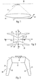
- Fig. 1 shows first schematically the application of the lamp provided with the reference numeral 1. This is arranged recessed at the bottom or in the opening of a ceiling 50, wherein below the lamp 1, an area, for example. A corridor is to be used as an escape route. In the case of an emergency, accordingly, the light 1 should be activated and illuminate this escape route over its length. Accordingly, no uniform light emission in all directions is desired. Instead, a light cone A is to be created, the extending significantly further in a first direction I than in a direction perpendicular thereto extending second direction II. In order to enable this radiation characteristic, a special optics has been created, by means of which the light emitted from a substantially point light source light is influenced in a desired manner.
- This optic according to the invention is the Fig. 2 to 5 removable.
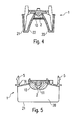
- the sectional views of the 4 and 5 show here the individual components of the lamp 1 according to the invention, whereas the views of the FIGS. 2 and 3 show primarily the shape of the optical means for influencing the light output.
- the luminaire 1 according to the invention as a punctiform light source preferably has an LED 2 which is arranged on a baseplate of the luminaire 1.
- the entire arrangement can be mounted on or in a ceiling.
- the light emitted by the LED 2 is essentially influenced in the desired manner by two different components, on the one hand by a lens arrangement 10 and on the other hand by a reflector arrangement 20.
- the shape of the lens arrangement 10 can in particular the sectional view in Fig. 5 be removed.
- the lens assembly 10 is accordingly designed approximately dome-shaped, however, has in the center above the LED 2 a low indentation 11, which is to be effected so that the light emitted by the LED 2 light along the first direction I is widened.
- the lens arrangement 10 is designed to be translation-symmetrical or translation-invariant, ie, the Fig. 5 Removable cross-sectional shape of the lens assembly 10 does not change along the second direction II. This also contributes to the desired expansion of the light in the first direction I.
- the desired asymmetric shape is achieved by the reflector arrangement 20, which has two reflectors 21 with reflection surfaces 22 arranged on both sides of the LED 2, as seen with respect to the second direction II.
- These reflection surfaces 22 are formed with respect to a rotation axis substantially rotationally symmetrical, wherein the axis of rotation parallel to the second Direction II runs.
- the axis of rotation R of the reflecting surfaces 22 - as in Figure 3 indicated by the center of the LED 2 run.
- this special configuration of the reflecting surfaces 22, the light emitted by the light source 2 and preformed by the lens assembly 10 light can be deformed in a particularly effective manner to the desired asymmetrical light cone.
- the entire arrangement occupies a relatively small size and accordingly a lamp can be created in a very compact manner.
- the outer edges of the reflectors 21 may - if desired - be rounded. However, they are preferred as in Fig. 5 represented angled designed. Accordingly, the entire arrangement can be easily inserted into a transparent cuboid housing.
Landscapes
- Physics & Mathematics (AREA)
- Engineering & Computer Science (AREA)
- General Engineering & Computer Science (AREA)
- General Physics & Mathematics (AREA)
- Optics & Photonics (AREA)
- Non-Portable Lighting Devices Or Systems Thereof (AREA)
- Endoscopes (AREA)
Description
- Die vorliegende Erfindung betrifft eine optische Anordnung gemäß dem Oberbegriff des Anspruchs 1, mit deren Hilfe eine asymmetrische Lichtabstrahlcharakteristik erzielt wird. Unter einer asymmetrischen Lichtabstrahlcharakteristik wird hierbei verstanden, dass die Erstreckung eines von der Leuchte abgegebenen Lichtkegels in einer ersten Richtung größer ist als in einer zu der ersten Richtung senkrecht verlaufenden zweiten Richtung.
- Leuchten der oben beschriebenen Art werden insbesondere als Rettungswegleuchten eingesetzt. Die Leuchten werden hierbei bspw. an der Decke eines Raumes oder eines Gangs montiert und dienen im Notfall dazu, den darunter befindlichen Rettungsweg mit einem länglichen Lichtkegel auszuleuchten. Dabei ist es in der Regel erwünscht, mit Hilfe optischer Mittel das Licht verhältnismäßig weniger Lichtquellen derart umzusetzen, dass der angesprochene längliche Lichtkegel erzielt wird.
- Aus dem Stand der Technik sind hierzu grundsätzlich zwei Lösungen bekannt, die in den
Fig. 6 und 7a bzw. 7b dargestellt sind. - Bei der ersten Variante gemäß
Fig. 6 sind entsprechend der schematischen Darstellung zwei punktförmige Lichtquellen - bspw. LEDs - 101 und 102 vorgesehen, welche in einem Winkel zueinander angeordnet sind und dementsprechend in jeweils verschiedene Richtungen Licht abstrahlen. Den Lichtquellen 101, 102 der Leuchte 100 können jeweils optische Element 103, 104 bspw. in Form von Linsen vorgeschaltet sein, über die dann letztendlich die gewünschte Lichtverteilung erzielt wird. Die Asymmetrie der Lichtabstrahlcharakteristik der Leuchte 100 wird allerdings in erster Linie durch die Nutzung zweier Lichtquellen erzielt. - Demgegenüber kommt bei der Leuchte 110 gemäß den
Fig. 7a und 7b lediglich eine einzelne Lichtquelle 111 zum Einsatz. Diese ist von einer rotationssymmetrischen Linse 112 umgeben, über die zunächst eine gleichmäßige Aufweitung des von der Lichtquelle 111 abgegebenen Lichtbündels erzielt wird. Die Verformung dieses Lichtbündels zu einem asymmetrischen Lichtkegel wird dann mit Hilfe einer Reflektoranordnung 113 erzielt, welche aus jeweils zwei Reflektorhalbschalen 114, 115 gebildet ist, die entsprechend der Ansicht vonFig. 7b , welche die Unterseite der Leuchte 110 darstellt, zu einer Linsenform zusammengesetzt sind. Diese in denFig. 7a und 7b dargestellte Konfiguration hat sich bewährt, da lediglich eine einzige Lichtquelle zum Einsatz kommt, allerdings führt sie zu verhältnismäßig großen Bauformen für die gesamte Leuchte. - Der vorliegenden Erfindung liegt deshalb die Aufgabe zugrunde, bislang bekannte Konzepte zur Realisierung einer asymmetrischen Lichtabstrahlcharakteristik derart weiter zu entwickeln, dass eine Leuchte mit optimalen lichttechnischen Eigenschaften erzielt wird, welche darüber hinaus allerdings auch in einer sehr kompakten Weise realisiert werden kann.
- Die Aufgabe wird durch eine Leuchte mit den Merkmalen des Anspruchs 1 gelöst. Vorteilhafte Weiterbildungen der Erfindung sind Gegenstand der abhängigen Ansprüche.
Die erfindungsgemäße optische Anordnung beruht wiederum auf dem Konzept, das Licht einer einzigen Lichtquelle mit Hilfe optischer Mittel zu einem Lichtkegel zu verformen, der sich in einer ersten Richtung weiter erstreckt als in einer zu der ersten Richtung senkrecht verlaufenden zweiten Richtung. Erfindungsgemäß ist nunmehr vorgesehen, dass die optischen Mittel eine der Lichtquelle zugeordnete Linsenanordnung aufweisen, welche bezüglich der zweiten Richtung translations-symmetrisch ausgebildet ist. Ferner sind im Hinblick auf die zweite Richtung zu beiden Seiten der Linsenanordnung zwei Reflektoren mit Reflektionsflächen vorgesehen, welche jeweils im Hinblick auf eine Rotationsachse der Leuchte im Wesentlichen rotations-symmetrisch ausgebildet sind. Es hat sich gezeigt, dass durch den Einsatz derartiger optischer Mittel das Licht der punktförmigen Lichtquelle in besonders effektiver Weise zu dem gewünschten asymmetrischen Lichtkegel verformt werden kann, wobei allerdings die optischen Mittel selbst sehr kompakt ausgestaltet sein können, so dass letztendlich eine Leuchte mit den gewünschten lichttechnischen Eigenschaften in kleiner Bauweise realisiert werden kann. - Gemäß der vorliegenden Erfindung wird dementsprechend eine Leuchte vorgeschlagen, welche eine im Wesentlichen punktförmige Lichtquelle sowie optische Mittel zur Beeinflussung des von der Lichtquelle abgegebenen Lichts aufweist, derart, dass die Erstreckung eines von der Leuchte abgegebenen Lichtkegels in einer ersten Richtung größer ist als in einer zu der ersten Richtung senkrecht verlaufenden zweiten Richtung, wobei erfindungsgemäß vorgesehen ist, dass die optischen Mittel eine der Lichtquelle zugeordnete Linsenanordnung, welche bezüglich der zweiten Richtung translations-symmetrisch ausgebildet ist, sowie zwei - bezüglich der zweiten Richtung - zu beiden Seiten der Linsenanordnung befindliche Reflektoren mit Reflektionsflächen aufweisen, welche jeweils im Hinblick auf eine Rotationsachse im Wesentlichen rotationssymmetrisch ausgebildet sind.
- Die Rotationsachsen der beiden Reflektionsflächen verlaufen vorzugsweise parallel zur zweiten Richtung, wobei insbesondere vorgesehen sein kann, dass die Rotationsachsen derart angeordnet sind, dass sie die Lichtquelle schneiden bzw. die Lichtquelle auf der gemeinsamen Rotationsachse angeordnet ist. Die Reflektionsflächen selbst weisen vorzugsweise im Schnitt eine Parabelform auf, wobei der Scheitel der Parabelform in etwa der Position der Lichtquelle entspricht.
- Die Begrenzungskanten der Reflektoren können abgerundet sein. Alternativ hierzu wäre allerdings auch eine abgewinkelte Ausgestaltung denkbar.
- Die Lichtquelle selbst ist vorzugsweise durch eine LED bzw. ein lichtemittierendes Halbleiterelement gebildet.
Erfindungsgemäß wird im Anspruch 1 eine optische Anordnung zur Beeinflussung des von einer im Wesentlichen punktförmigen Lichtquelle abgegebenen Lichts derart, dass die Erstreckung eines von der Lichtquelle abgegebenen Lichtkegels in einer ersten Richtung größer ist als in einer zu der ersten Richtung senkrecht verlaufenden zweiten Richtung, vorgeschlagen, wobei die optische Anordnung eine Linsenanordnung, welche bezüglich der zweiten Richtung translations-symmetrisch ausgebildet ist, sowie zwei - bezüglich der zweiten Richtung - zu beiden Seiten der Linsenanordnung befindliche Reflektoren mit Reflektionsflächen aufweisen, welche jeweils im Hinblick auf eine Rotationsachse im Wesentlichen rotations-symmetrisch ausgebildet sind. - Nachfolgend soll die Erfindung anhand der beiliegenden Zeichnung näher erläutert werden. Es zeigen:
- Fig. 1
- schematisch die Lichtabstrahlcharakteristik der erfindungsgemäßen Leuchte;
- Fig. 2
- eine Ansicht der optischen Mittel der erfindungsgemäßen Leuchte von unten;
- Fig. 3
- eine seitliche Ansicht der optischen Mittel;
- Fig. 4
- eine Schnittdarstellung der Leuchte entlang dem Schnitt A-A von
Fig. 2 ; - Fig. 5
- eine weitere Schnittdarstellung der Leuchte entlang dem Schnitt B-B von
Fig. 2 ; - Fig. 6
- eine erste aus dem Stand der Technik bekannte Lösung zur Realisierung einer asymmetrischen Lichtabstrahlcharakteristik und
- Fig. 7a und 7b
- eine weitere aus dem Stand der Technik bekannte Lösung einer Leuchte mit asymmetrischer Lichtabstrahlcharakteristik.
-
Fig. 1 zeigt zunächst schematisch das Einsatzgebiet der mit dem Bezugszeichen 1 versehenen Leuchte. Diese ist an der Unterseite oder in der Öffnung einer Decke 50 versenkt angeordnet, wobei sich unterhalb der Leuchte 1 ein Bereich, bspw. ein Gang befindet, der als Fluchtweg genutzt werden soll. Im Falle eines Notfalls soll dementsprechend die Leuchte 1 aktiviert werden und diesen Fluchtweg über seine Länge hinweg ausleuchten. Dementsprechend ist keine gleichmäßige Lichtabstrahlung in alle Richtungen erwünscht. Stattdessen soll ein Lichtkegel A geschaffen werden, der sich in einer ersten Richtung I deutlich weiter erstreckt als in einer senkrecht hierzu verlaufenden zweiten Richtung II. Um diese Abstrahlcharakteristik zu ermöglichen, wurde eine spezielle Optik geschaffen, mit deren Hilfe das von einer im Wesentlichen punktförmigen Lichtquelle abgegebene Licht in gewünschter Weise beeinflusst wird. Diese erfindungsgemäße Optik ist denFig. 2 bis 5 entnehmbar. Die Schnittdarstellungen derFig. 4 und 5 zeigen hierbei die einzelnen Komponenten der erfindungsgemäßen Leuchte 1, während hingegen die Ansichten derFig. 2 und 3 in erster Linie die Form der optischen Mittel zur Beeinflussung der Lichtabgabe zeigen. - Gemäß den Darstellungen weist die erfindungsgemäße Leuchte 1 als punktförmige Lichtquelle vorzugsweise eine LED 2 auf, welche auf einer Basisplatine der Leuchte 1 angeordnet ist. Mit Hilfe nicht näher beschriebener Montage- bzw. Halterungsmittel 5 kann die gesamte Anordnung an bzw. in einer Decke montiert werden.
- Das von der LED 2 emittierte Licht wird - wie bereits erwähnt - im Wesentlichen durch zwei verschiedene Komponenten in gewünschter Weise beeinflusst, einerseits durch eine Linsenanordnung 10 sowie andererseits durch eine Reflektoranordnung 20.
- Die Form der Linsenanordnung 10 kann insbesondere der Schnittdarstellung in
Fig. 5 entnommen werden. Die Linsenanordnung 10 ist dementsprechend in etwa kuppelförmig ausgestaltet, weist allerdings im Zentrum oberhalb der LED 2 eine geringe Eindellung 11 auf, wodurch bewirkt werden soll, dass das von der LED 2 abgegebene Licht entlang der ersten Richtung I aufgeweitet wird. Bezüglich der zweiten Richtung II hingegen ist die Linsenanordnung 10 translations-symmetrisch bzw. translations-invariant ausgestaltet, d.h., dieFig. 5 entnehmbare Querschnittsform der Linsenanordnung 10 ändert sich entlang der zweiten Richtung II nicht. Auch dies trägt zu der gewünschten Aufweitung des Lichts in der ersten Richtung I bei. - Die entscheidende Verformung des Lichtbündels zu der in
Fig. 1 dargestellten gewünschten asymmetrischen Form erfolgt schließlich durch die Reflektoranordnung 20, welche - im Hinblick auf die zweite Richtung II gesehen - zwei zu beiden Seiten der LED 2 angeordnete Reflektoren 21 mit Reflektionsflächen 22 aufweist. Diese Reflektionsflächen 22 sind im Hinblick auf eine Rotationsachse im Wesentlichen rotations-symmetrisch ausgebildet, wobei die Rotationsachse parallel zur zweiten Richtung II verläuft. Insbesondere kann die Rotationsachse R der Reflektionsflächen 22 - wie inFig.3 angedeutet -durch das Zentrum der LED 2 verlaufen. Im Schnitt gesehen weisen dabei die Reflektionsflächen 22 - wie inFig. 4 dargestellt - vorzugsweise eine Parabelform auf, wobei der Scheitel der Parabel wiederum durch die Lichtquelle 2 gebildet ist. - Es hat sich gezeigt, dass durch diese spezielle Ausgestaltung der Reflektionsflächen 22 das von der Lichtquelle 2 abgegebene und durch die Linsenanordnung 10 vorgeformte Licht in besonders effektiver Weise zu dem gewünschten asymmetrischen Lichtkegel verformt werden kann. Dabei besteht ein besonderer Vorteil darin, dass die gesamte Anordnung eine verhältnismäßig geringe Größe einnimmt und dementsprechend eine Leuchte in sehr kompakter Weise geschaffen werden kann.
- Die Außenkanten der Reflektoren 21 können - sofern gewünscht - abgerundet sein. Bevorzugt sind sie allerdings wie in
Fig. 5 dargestellt abgewinkelt ausgestaltet. Die gesamte Anordnung lässt sich dementsprechend ohne Weiteres in ein transparentes quaderförmiges Gehäuse einfügen.
Claims (9)
- Optische Anordnung zur Beeinflussung des von einer im Wesentlichen punktförmigen Lichtquelle (2) abgegebenen Lichts derart, dass die Erstreckung eines von der Lichtquelle (2) abgegebenen Lichtkegels in einer ersten Richtung (I) größer ist als in einer zu der ersten Richtung (I) senkrecht verlaufenden zweiten Richtung (II),
dadurch gekennzeichnet,
dass die optische Anordnung aufweist:a) eine Linsenanordnung (10), welche bezüglich der zweiten Richtung (II) translations-symmetrisch ausgebildet ist, sowieb) zwei - bezüglich der zweiten Richtung (II) - zu beiden Seiten der Linsenanordnung (10) befindliche Reflektoren (21) mit Reflexionsflächen (22), welche jeweils im Hinblick auf eine Rotationsachse (R) im Wesentlichen rotations-symmetrisch ausgebildet sind. - Leuchte (1) mit
einer im Wesentlichen punktförmigen Lichtquelle (2) sowie
einer optischen Anordnung gemäß Anspruch 1. - Leuchte nach Anspruch 2,
dadurch gekennzeichnet,
dass die Rotationsachsen (R) der beiden Reflexionsflächen (22) parallel zur zweiten Richtung (II) verlaufen. - Leuchte nach Anspruch 2 oder 3,
dadurch gekennzeichnet,
dass die Lichtquelle (2) in etwa auf den Rotationsachsen (R) der beiden Reflexionsflächen (22) angeordnet ist. - Leuchte nach einem der Ansprüche 2-4,
dadurch gekennzeichnet,
dass die beiden Reflexionsflächen (22) im Schnitt eine Parabelform aufweisen, wobei der Scheitel der Parabel in etwa der Position der Lichtquelle (2) entspricht. - Leuchte nach einem der Ansprüche 2-5,
dadurch gekennzeichnet,
dass die Begrenzungskanten der Reflektoren (21) abgerundet sind. - Leuchte nach einem der Ansprüche 2-5,
dadurch gekennzeichnet,
dass die Begrenzungskanten der Reflektoren (22) abgewinkelt sind. - Leuchte nach Anspruch 7,
dadurch gekennzeichnet,
dass diese ein quaderförmiges transparentes Gehäuse aufweist. - Leuchte nach einem der Ansprüche 2-8,
dadurch gekennzeichnet,
dass die Lichtquelle (2) durch mindestens eine LED bzw. ein lichtemittierendes Halbleiterelement gebildet ist.
Applications Claiming Priority (2)
| Application Number | Priority Date | Filing Date | Title |
|---|---|---|---|
| DE102008016496A DE102008016496A1 (de) | 2008-03-31 | 2008-03-31 | Leuchte mit punktförmiger Lichtquelle und asymmetrischer Lichtabstrahlcharakteristik |
| PCT/EP2009/002295 WO2009121538A1 (de) | 2008-03-31 | 2009-03-30 | Leuchte mit punktförmiger lichtquelle und asymmetrischer lichtabstrahlcharakteristik |
Publications (2)
| Publication Number | Publication Date |
|---|---|
| EP2257734A1 EP2257734A1 (de) | 2010-12-08 |
| EP2257734B1 true EP2257734B1 (de) | 2014-09-03 |
Family
ID=40999778
Family Applications (1)
| Application Number | Title | Priority Date | Filing Date |
|---|---|---|---|
| EP09727429.4A Not-in-force EP2257734B1 (de) | 2008-03-31 | 2009-03-30 | Optische anordnung für leuchte mit punktförmiger lichtquelle und asymmetrischer lichtabstrahlcharakteristik |
Country Status (4)
| Country | Link |
|---|---|
| EP (1) | EP2257734B1 (de) |
| CN (1) | CN101981369B (de) |
| DE (1) | DE102008016496A1 (de) |
| WO (1) | WO2009121538A1 (de) |
Families Citing this family (3)
| Publication number | Priority date | Publication date | Assignee | Title |
|---|---|---|---|---|
| DE102010019436A1 (de) * | 2010-05-05 | 2011-11-10 | Christian Bartenbach | Wand- und/oder Deckenleuchte |
| DE102010038921B4 (de) * | 2010-08-04 | 2021-03-25 | Osram Gmbh | Optische Vorrichtung und Beleuchtungseinheit mit optischer Vorrichtung |
| JP5704005B2 (ja) | 2011-07-26 | 2015-04-22 | 東芝ライテック株式会社 | 電球形ledランプ |
Family Cites Families (12)
| Publication number | Priority date | Publication date | Assignee | Title |
|---|---|---|---|---|
| DE29716999U1 (de) * | 1997-09-23 | 1998-01-08 | Semperlux GmbH Lichttechnisches Werk, 12277 Berlin | Prismierte Lamellen zur Abblendung und Lenkung von Licht |
| AU2004284713B2 (en) * | 2003-10-06 | 2007-11-15 | Signify Holding B.V. | Method and apparatus for light collection, distribution and zoom |
| JP2005196983A (ja) * | 2003-12-26 | 2005-07-21 | Matsushita Electric Works Ltd | 発光ダイオードを用いた照明器具 |
| CN1977127B (zh) * | 2004-03-30 | 2010-08-04 | 照明管理解决方案公司 | 用于改进的照明区域填充的设备和方法 |
| JP4537822B2 (ja) * | 2004-10-14 | 2010-09-08 | スタンレー電気株式会社 | 灯具 |
| DE102005035720A1 (de) * | 2005-07-29 | 2007-02-08 | Zumtobel Staff Gmbh | Leuchte mit einer langgestreckten Lichtquelle und mit einem ebenfalls langgestreckten Lichtleitelement |
| DE102006016021A1 (de) * | 2006-04-05 | 2007-10-11 | Zumtobel Lighting Gmbh | Reflektorleuchte |
| US7607792B2 (en) * | 2006-12-22 | 2009-10-27 | Hong Kong Applieed Science and Technology Research Institute Co. LTd. | Light-emitting devices and lens therefor |
| JP5349453B2 (ja) * | 2007-04-05 | 2013-11-20 | コーニンクレッカ フィリップス エヌ ヴェ | 光ビーム整形器 |
| CN100578077C (zh) * | 2007-07-30 | 2010-01-06 | 深圳市邦贝尔电子有限公司 | Led隧道灯 |
| ATE486245T1 (de) * | 2007-09-20 | 2010-11-15 | Siteco Beleuchtungstech Gmbh | Trägerelement mit leuchtdiodeneinheiten |
| WO2009046586A1 (en) * | 2007-10-13 | 2009-04-16 | He Shan Lide Electronic Enterprise Company Ltd. | A method of providing light distribution, a cup for providing light distribution, and a roadway lamp using the cup |
-
2008
- 2008-03-31 DE DE102008016496A patent/DE102008016496A1/de not_active Withdrawn
-
2009
- 2009-03-30 WO PCT/EP2009/002295 patent/WO2009121538A1/de not_active Ceased
- 2009-03-30 EP EP09727429.4A patent/EP2257734B1/de not_active Not-in-force
- 2009-03-30 CN CN2009801117645A patent/CN101981369B/zh not_active Expired - Fee Related
Also Published As
| Publication number | Publication date |
|---|---|
| DE102008016496A1 (de) | 2009-10-01 |
| CN101981369B (zh) | 2012-11-07 |
| EP2257734A1 (de) | 2010-12-08 |
| WO2009121538A1 (de) | 2009-10-08 |
| CN101981369A (zh) | 2011-02-23 |
Similar Documents
| Publication | Publication Date | Title |
|---|---|---|
| EP2204604B1 (de) | Leuchte | |
| DE102004042915B4 (de) | Leuchte zur Ausleuchtung von Gebäudeflächen oder Gebäudeteilflächen | |
| EP2729838B1 (de) | Optisches element | |
| EP2019253B1 (de) | Leuchte zur Ausleuchtung einer Gebäudefläche | |
| EP1979668B1 (de) | Leuchte mit einem kastenförmigen leuchtengehäuse und einem lichtaustrittselement | |
| EP3037719B1 (de) | Led-linsenkörper zur erzeugung eines direkt- und indirektlichtanteils | |
| EP1077344A2 (de) | Leuchte | |
| EP1132680A1 (de) | Leuchte mit inhomogener Lichtabstrahlung | |
| EP3165818B1 (de) | Innen- oder aussenleuchte, insbesondere strassenleuchte, mit verlagerbarer freiformlinse | |
| EP1338845B1 (de) | Leuchte | |
| EP2257734A1 (de) | Leuchte mit punktförmiger lichtquelle und asymmetrischer lichtabstrahlcharakteristik | |
| EP3671026B1 (de) | Leuchte | |
| EP2812629B1 (de) | Reflektorstrahler | |
| DE20004188U1 (de) | Leuchte | |
| EP1608909B1 (de) | Lichtbeeinflussungselement | |
| EP0638764B2 (de) | Vorwiegend direkt strahlende Innenleuchte | |
| EP1132679B1 (de) | Leuchtensystem | |
| DE202014011256U1 (de) | Abdeckungselement für Flächenleuchte | |
| WO2023198456A1 (de) | Lichtleitelement für rettungszeichenleuchte | |
| DE102006016021A1 (de) | Reflektorleuchte | |
| DE102009058308B4 (de) | Reflektor für Leuchten mit Ellipsoid-Facetten | |
| DE102020134057B4 (de) | LED-Leuchte, insbesondere Straßenleuchte, mit Linsenarray | |
| EP2578930B1 (de) | Lichtmodul für eine Außenleuchte | |
| EP1467139B1 (de) | Beleuchtungsvorrichtung | |
| DE202012100628U1 (de) | Leuchte mit einem länglichen Gehäuse und Anbauelement hierfür |
Legal Events
| Date | Code | Title | Description |
|---|---|---|---|
| PUAI | Public reference made under article 153(3) epc to a published international application that has entered the european phase |
Free format text: ORIGINAL CODE: 0009012 |
|
| 17P | Request for examination filed |
Effective date: 20100831 |
|
| AK | Designated contracting states |
Kind code of ref document: A1 Designated state(s): AT BE BG CH CY CZ DE DK EE ES FI FR GB GR HR HU IE IS IT LI LT LU LV MC MK MT NL NO PL PT RO SE SI SK TR |
|
| AX | Request for extension of the european patent |
Extension state: AL BA RS |
|
| DAX | Request for extension of the european patent (deleted) | ||
| REG | Reference to a national code |
Ref country code: DE Ref legal event code: R079 Ref document number: 502009009894 Country of ref document: DE Free format text: PREVIOUS MAIN CLASS: F21V0005040000 Ipc: F21V0007000000 |
|
| RIC1 | Information provided on ipc code assigned before grant |
Ipc: F21K 99/00 20100101AFI20140306BHEP |
|
| GRAP | Despatch of communication of intention to grant a patent |
Free format text: ORIGINAL CODE: EPIDOSNIGR1 |
|
| RIC1 | Information provided on ipc code assigned before grant |
Ipc: F21Y 101/02 20060101ALN20140327BHEP Ipc: F21V 7/00 20060101AFI20140327BHEP |
|
| INTG | Intention to grant announced |
Effective date: 20140410 |
|
| GRAS | Grant fee paid |
Free format text: ORIGINAL CODE: EPIDOSNIGR3 |
|
| GRAA | (expected) grant |
Free format text: ORIGINAL CODE: 0009210 |
|
| AK | Designated contracting states |
Kind code of ref document: B1 Designated state(s): AT BE BG CH CY CZ DE DK EE ES FI FR GB GR HR HU IE IS IT LI LT LU LV MC MK MT NL NO PL PT RO SE SI SK TR |
|
| REG | Reference to a national code |
Ref country code: GB Ref legal event code: FG4D Free format text: NOT ENGLISH |
|
| REG | Reference to a national code |
Ref country code: AT Ref legal event code: REF Ref document number: 685819 Country of ref document: AT Kind code of ref document: T Effective date: 20140915 Ref country code: CH Ref legal event code: EP Ref country code: CH Ref legal event code: NV Representative=s name: FIAMMENGHI-FIAMMENGHI, CH |
|
| REG | Reference to a national code |
Ref country code: IE Ref legal event code: FG4D Free format text: LANGUAGE OF EP DOCUMENT: GERMAN |
|
| REG | Reference to a national code |
Ref country code: DE Ref legal event code: R096 Ref document number: 502009009894 Country of ref document: DE Effective date: 20141016 |
|
| PG25 | Lapsed in a contracting state [announced via postgrant information from national office to epo] |
Ref country code: NO Free format text: LAPSE BECAUSE OF FAILURE TO SUBMIT A TRANSLATION OF THE DESCRIPTION OR TO PAY THE FEE WITHIN THE PRESCRIBED TIME-LIMIT Effective date: 20141203 Ref country code: SE Free format text: LAPSE BECAUSE OF FAILURE TO SUBMIT A TRANSLATION OF THE DESCRIPTION OR TO PAY THE FEE WITHIN THE PRESCRIBED TIME-LIMIT Effective date: 20140903 Ref country code: FI Free format text: LAPSE BECAUSE OF FAILURE TO SUBMIT A TRANSLATION OF THE DESCRIPTION OR TO PAY THE FEE WITHIN THE PRESCRIBED TIME-LIMIT Effective date: 20140903 Ref country code: ES Free format text: LAPSE BECAUSE OF FAILURE TO SUBMIT A TRANSLATION OF THE DESCRIPTION OR TO PAY THE FEE WITHIN THE PRESCRIBED TIME-LIMIT Effective date: 20140903 Ref country code: LT Free format text: LAPSE BECAUSE OF FAILURE TO SUBMIT A TRANSLATION OF THE DESCRIPTION OR TO PAY THE FEE WITHIN THE PRESCRIBED TIME-LIMIT Effective date: 20140903 Ref country code: GR Free format text: LAPSE BECAUSE OF FAILURE TO SUBMIT A TRANSLATION OF THE DESCRIPTION OR TO PAY THE FEE WITHIN THE PRESCRIBED TIME-LIMIT Effective date: 20141204 |
|
| REG | Reference to a national code |
Ref country code: NL Ref legal event code: VDEP Effective date: 20140903 |
|
| REG | Reference to a national code |
Ref country code: LT Ref legal event code: MG4D |
|
| PG25 | Lapsed in a contracting state [announced via postgrant information from national office to epo] |
Ref country code: CY Free format text: LAPSE BECAUSE OF FAILURE TO SUBMIT A TRANSLATION OF THE DESCRIPTION OR TO PAY THE FEE WITHIN THE PRESCRIBED TIME-LIMIT Effective date: 20140903 Ref country code: HR Free format text: LAPSE BECAUSE OF FAILURE TO SUBMIT A TRANSLATION OF THE DESCRIPTION OR TO PAY THE FEE WITHIN THE PRESCRIBED TIME-LIMIT Effective date: 20140903 Ref country code: LV Free format text: LAPSE BECAUSE OF FAILURE TO SUBMIT A TRANSLATION OF THE DESCRIPTION OR TO PAY THE FEE WITHIN THE PRESCRIBED TIME-LIMIT Effective date: 20140903 |
|
| PG25 | Lapsed in a contracting state [announced via postgrant information from national office to epo] |
Ref country code: NL Free format text: LAPSE BECAUSE OF FAILURE TO SUBMIT A TRANSLATION OF THE DESCRIPTION OR TO PAY THE FEE WITHIN THE PRESCRIBED TIME-LIMIT Effective date: 20140903 |
|
| PG25 | Lapsed in a contracting state [announced via postgrant information from national office to epo] |
Ref country code: SK Free format text: LAPSE BECAUSE OF FAILURE TO SUBMIT A TRANSLATION OF THE DESCRIPTION OR TO PAY THE FEE WITHIN THE PRESCRIBED TIME-LIMIT Effective date: 20140903 Ref country code: IS Free format text: LAPSE BECAUSE OF FAILURE TO SUBMIT A TRANSLATION OF THE DESCRIPTION OR TO PAY THE FEE WITHIN THE PRESCRIBED TIME-LIMIT Effective date: 20150103 Ref country code: EE Free format text: LAPSE BECAUSE OF FAILURE TO SUBMIT A TRANSLATION OF THE DESCRIPTION OR TO PAY THE FEE WITHIN THE PRESCRIBED TIME-LIMIT Effective date: 20140903 Ref country code: CZ Free format text: LAPSE BECAUSE OF FAILURE TO SUBMIT A TRANSLATION OF THE DESCRIPTION OR TO PAY THE FEE WITHIN THE PRESCRIBED TIME-LIMIT Effective date: 20140903 Ref country code: PT Free format text: LAPSE BECAUSE OF FAILURE TO SUBMIT A TRANSLATION OF THE DESCRIPTION OR TO PAY THE FEE WITHIN THE PRESCRIBED TIME-LIMIT Effective date: 20150105 Ref country code: RO Free format text: LAPSE BECAUSE OF FAILURE TO SUBMIT A TRANSLATION OF THE DESCRIPTION OR TO PAY THE FEE WITHIN THE PRESCRIBED TIME-LIMIT Effective date: 20140903 |
|
| PG25 | Lapsed in a contracting state [announced via postgrant information from national office to epo] |
Ref country code: PL Free format text: LAPSE BECAUSE OF FAILURE TO SUBMIT A TRANSLATION OF THE DESCRIPTION OR TO PAY THE FEE WITHIN THE PRESCRIBED TIME-LIMIT Effective date: 20140903 |
|
| REG | Reference to a national code |
Ref country code: DE Ref legal event code: R097 Ref document number: 502009009894 Country of ref document: DE |
|
| PLBE | No opposition filed within time limit |
Free format text: ORIGINAL CODE: 0009261 |
|
| STAA | Information on the status of an ep patent application or granted ep patent |
Free format text: STATUS: NO OPPOSITION FILED WITHIN TIME LIMIT |
|
| PG25 | Lapsed in a contracting state [announced via postgrant information from national office to epo] |
Ref country code: DK Free format text: LAPSE BECAUSE OF FAILURE TO SUBMIT A TRANSLATION OF THE DESCRIPTION OR TO PAY THE FEE WITHIN THE PRESCRIBED TIME-LIMIT Effective date: 20140903 |
|
| 26N | No opposition filed |
Effective date: 20150604 |
|
| PG25 | Lapsed in a contracting state [announced via postgrant information from national office to epo] |
Ref country code: IT Free format text: LAPSE BECAUSE OF FAILURE TO SUBMIT A TRANSLATION OF THE DESCRIPTION OR TO PAY THE FEE WITHIN THE PRESCRIBED TIME-LIMIT Effective date: 20140903 |
|
| PG25 | Lapsed in a contracting state [announced via postgrant information from national office to epo] |
Ref country code: MC Free format text: LAPSE BECAUSE OF FAILURE TO SUBMIT A TRANSLATION OF THE DESCRIPTION OR TO PAY THE FEE WITHIN THE PRESCRIBED TIME-LIMIT Effective date: 20140903 Ref country code: LU Free format text: LAPSE BECAUSE OF FAILURE TO SUBMIT A TRANSLATION OF THE DESCRIPTION OR TO PAY THE FEE WITHIN THE PRESCRIBED TIME-LIMIT Effective date: 20150330 |
|
| PG25 | Lapsed in a contracting state [announced via postgrant information from national office to epo] |
Ref country code: SI Free format text: LAPSE BECAUSE OF FAILURE TO SUBMIT A TRANSLATION OF THE DESCRIPTION OR TO PAY THE FEE WITHIN THE PRESCRIBED TIME-LIMIT Effective date: 20140903 |
|
| REG | Reference to a national code |
Ref country code: IE Ref legal event code: MM4A |
|
| PG25 | Lapsed in a contracting state [announced via postgrant information from national office to epo] |
Ref country code: IE Free format text: LAPSE BECAUSE OF NON-PAYMENT OF DUE FEES Effective date: 20150330 |
|
| REG | Reference to a national code |
Ref country code: FR Ref legal event code: PLFP Year of fee payment: 8 |
|
| PG25 | Lapsed in a contracting state [announced via postgrant information from national office to epo] |
Ref country code: MT Free format text: LAPSE BECAUSE OF FAILURE TO SUBMIT A TRANSLATION OF THE DESCRIPTION OR TO PAY THE FEE WITHIN THE PRESCRIBED TIME-LIMIT Effective date: 20140903 |
|
| REG | Reference to a national code |
Ref country code: FR Ref legal event code: PLFP Year of fee payment: 9 |
|
| PG25 | Lapsed in a contracting state [announced via postgrant information from national office to epo] |
Ref country code: BG Free format text: LAPSE BECAUSE OF FAILURE TO SUBMIT A TRANSLATION OF THE DESCRIPTION OR TO PAY THE FEE WITHIN THE PRESCRIBED TIME-LIMIT Effective date: 20140903 Ref country code: HU Free format text: LAPSE BECAUSE OF FAILURE TO SUBMIT A TRANSLATION OF THE DESCRIPTION OR TO PAY THE FEE WITHIN THE PRESCRIBED TIME-LIMIT; INVALID AB INITIO Effective date: 20090330 |
|
| PG25 | Lapsed in a contracting state [announced via postgrant information from national office to epo] |
Ref country code: BE Free format text: LAPSE BECAUSE OF NON-PAYMENT OF DUE FEES Effective date: 20150331 |
|
| PG25 | Lapsed in a contracting state [announced via postgrant information from national office to epo] |
Ref country code: TR Free format text: LAPSE BECAUSE OF FAILURE TO SUBMIT A TRANSLATION OF THE DESCRIPTION OR TO PAY THE FEE WITHIN THE PRESCRIBED TIME-LIMIT Effective date: 20140903 |
|
| REG | Reference to a national code |
Ref country code: FR Ref legal event code: PLFP Year of fee payment: 10 |
|
| PG25 | Lapsed in a contracting state [announced via postgrant information from national office to epo] |
Ref country code: MK Free format text: LAPSE BECAUSE OF FAILURE TO SUBMIT A TRANSLATION OF THE DESCRIPTION OR TO PAY THE FEE WITHIN THE PRESCRIBED TIME-LIMIT Effective date: 20140903 |
|
| REG | Reference to a national code |
Ref country code: DE Ref legal event code: R084 Ref document number: 502009009894 Country of ref document: DE |
|
| REG | Reference to a national code |
Ref country code: CH Ref legal event code: PK Free format text: BERICHTIGUNGEN |
|
| RIC2 | Information provided on ipc code assigned after grant |
Ipc: F21Y 101/02 20000101ALN20140327BHEP Ipc: F21V 7/00 20060101AFI20140327BHEP |
|
| PGFP | Annual fee paid to national office [announced via postgrant information from national office to epo] |
Ref country code: RO Payment date: 20190308 Year of fee payment: 11 |
|
| PGFP | Annual fee paid to national office [announced via postgrant information from national office to epo] |
Ref country code: AT Payment date: 20190328 Year of fee payment: 11 |
|
| REG | Reference to a national code |
Ref country code: CH Ref legal event code: PL |
|
| REG | Reference to a national code |
Ref country code: AT Ref legal event code: MM01 Ref document number: 685819 Country of ref document: AT Kind code of ref document: T Effective date: 20200330 |
|
| PG25 | Lapsed in a contracting state [announced via postgrant information from national office to epo] |
Ref country code: LI Free format text: LAPSE BECAUSE OF NON-PAYMENT OF DUE FEES Effective date: 20200331 Ref country code: AT Free format text: LAPSE BECAUSE OF NON-PAYMENT OF DUE FEES Effective date: 20200330 Ref country code: CH Free format text: LAPSE BECAUSE OF NON-PAYMENT OF DUE FEES Effective date: 20200331 |
|
| PGFP | Annual fee paid to national office [announced via postgrant information from national office to epo] |
Ref country code: FR Payment date: 20230323 Year of fee payment: 15 |
|
| PGFP | Annual fee paid to national office [announced via postgrant information from national office to epo] |
Ref country code: GB Payment date: 20230321 Year of fee payment: 15 Ref country code: DE Payment date: 20230328 Year of fee payment: 15 |
|
| P01 | Opt-out of the competence of the unified patent court (upc) registered |
Effective date: 20230530 |
|
| REG | Reference to a national code |
Ref country code: DE Ref legal event code: R119 Ref document number: 502009009894 Country of ref document: DE |
|
| GBPC | Gb: european patent ceased through non-payment of renewal fee |
Effective date: 20240330 |
|
| PG25 | Lapsed in a contracting state [announced via postgrant information from national office to epo] |
Ref country code: DE Free format text: LAPSE BECAUSE OF NON-PAYMENT OF DUE FEES Effective date: 20241001 |
|
| PG25 | Lapsed in a contracting state [announced via postgrant information from national office to epo] |
Ref country code: GB Free format text: LAPSE BECAUSE OF NON-PAYMENT OF DUE FEES Effective date: 20240330 |
|
| PG25 | Lapsed in a contracting state [announced via postgrant information from national office to epo] |
Ref country code: FR Free format text: LAPSE BECAUSE OF NON-PAYMENT OF DUE FEES Effective date: 20240331 |
|
| PG25 | Lapsed in a contracting state [announced via postgrant information from national office to epo] |
Ref country code: GB Free format text: LAPSE BECAUSE OF NON-PAYMENT OF DUE FEES Effective date: 20240330 Ref country code: FR Free format text: LAPSE BECAUSE OF NON-PAYMENT OF DUE FEES Effective date: 20240331 Ref country code: DE Free format text: LAPSE BECAUSE OF NON-PAYMENT OF DUE FEES Effective date: 20241001 |