EP2257397B1 - Segment de guidage de barre coulée - Google Patents
Segment de guidage de barre coulée Download PDFInfo
- Publication number
- EP2257397B1 EP2257397B1 EP09724438A EP09724438A EP2257397B1 EP 2257397 B1 EP2257397 B1 EP 2257397B1 EP 09724438 A EP09724438 A EP 09724438A EP 09724438 A EP09724438 A EP 09724438A EP 2257397 B1 EP2257397 B1 EP 2257397B1
- Authority
- EP
- European Patent Office
- Prior art keywords
- strand guide
- strand
- cross beam
- guide roller
- longitudinal slot
- Prior art date
- Legal status (The legal status is an assumption and is not a legal conclusion. Google has not performed a legal analysis and makes no representation as to the accuracy of the status listed.)
- Not-in-force
Links
- 238000009749 continuous casting Methods 0.000 claims abstract description 10
- 239000002184 metal Substances 0.000 claims abstract description 3
- 238000009434 installation Methods 0.000 claims 1
- 238000005266 casting Methods 0.000 description 8
- 229910000831 Steel Inorganic materials 0.000 description 2
- 238000005452 bending Methods 0.000 description 2
- 230000000052 comparative effect Effects 0.000 description 2
- 230000000694 effects Effects 0.000 description 2
- 239000007788 liquid Substances 0.000 description 2
- 239000007858 starting material Substances 0.000 description 2
- 239000010959 steel Substances 0.000 description 2
- 229910001208 Crucible steel Inorganic materials 0.000 description 1
- 230000000712 assembly Effects 0.000 description 1
- 238000000429 assembly Methods 0.000 description 1
- 230000005540 biological transmission Effects 0.000 description 1
- 230000015572 biosynthetic process Effects 0.000 description 1
- 238000001816 cooling Methods 0.000 description 1
- 238000005336 cracking Methods 0.000 description 1
- 238000004519 manufacturing process Methods 0.000 description 1
- 238000005457 optimization Methods 0.000 description 1
- 238000009751 slip forming Methods 0.000 description 1
- IHQKEDIOMGYHEB-UHFFFAOYSA-M sodium dimethylarsinate Chemical class [Na+].C[As](C)([O-])=O IHQKEDIOMGYHEB-UHFFFAOYSA-M 0.000 description 1
Images


Classifications
-
- B—PERFORMING OPERATIONS; TRANSPORTING
- B22—CASTING; POWDER METALLURGY
- B22D—CASTING OF METALS; CASTING OF OTHER SUBSTANCES BY THE SAME PROCESSES OR DEVICES
- B22D11/00—Continuous casting of metals, i.e. casting in indefinite lengths
- B22D11/12—Accessories for subsequent treating or working cast stock in situ
- B22D11/128—Accessories for subsequent treating or working cast stock in situ for removing
-
- B—PERFORMING OPERATIONS; TRANSPORTING
- B22—CASTING; POWDER METALLURGY
- B22D—CASTING OF METALS; CASTING OF OTHER SUBSTANCES BY THE SAME PROCESSES OR DEVICES
- B22D11/00—Continuous casting of metals, i.e. casting in indefinite lengths
- B22D11/12—Accessories for subsequent treating or working cast stock in situ
- B22D11/1206—Accessories for subsequent treating or working cast stock in situ for plastic shaping of strands
Definitions
- the invention relates to a strand guide segment for supporting and guiding a cast metal strand in a strand guide of a continuous casting with a plurality of strand guide rollers which are supported in a segment frame of the strand guide segment on cross members, wherein at least one of the cross member is plate-shaped.
- the invention relates to a strand guide segment for supporting and guiding a cast steel strand.
- a thin slab or a strip - strand guide rollers arranged individually or in strand guide segments.
- adjustable and drivable strand guide rollers are provided at intervals from one another on the cast strand and at the start of casting on the starter strand.
- a strand guide segment of the type described above is from the WO 01/94051 A1 already known. It comprises two rows of strand guide rollers supported on cross beams, the cross beams being arranged in successive segment frames.
- a strand guide rollers supporting cross member is guided on vertical guides in the segment frame movable and can be made to the cast strand or the Anfahrstrang.
- the necessary contact force is applied by a clamping device designed as a pressure cylinder, which acts centrally on the cross member. The central contact force causes a deflection of the arc inside cross member and the strand guide rollers supported thereon.
- a desired convex (crowned) cross-sectional shape of the cast strand is achieved when the outer arch portion and the inner arch portion of a segment are braced by acting on the four segment corners clamping cylinders.
- a similar deformation pattern is achieved in a cross member with employed strand guide rollers when two adjusting devices engage in each case in the end regions of the cross member thereto.
- Such an embodiment is known from WO 2006/037555 A1 already known. However, this embodiment has the disadvantage that two synchronously operating pressure medium cylinder must be provided.
- FIGS WO 2008/022731 A1 different ways known. These consist either in a crowning of the interposed strand guide rollers or in a resilient design of the outer bearing in relation to the intermediate bearings or in an inclined position of the strand guide rollers. Ultimately, all of these options are structurally complex and considerably increase the costs of spare parts management in the wear parts, especially the strand guide rollers and roller bearings.
- the object of the present invention is to avoid the disadvantages of the known prior art and to propose a strand guide segment with at least one strand guide rollers supporting cross member of the type described above, in which always a convex in cross-section of the cast strand (convex) cross-sectional shape is ensured.
- a particularly advantageous embodiment is that at least one cross member supporting a strand guide roller is slidably formed in the segment frame normal to the direction of longitudinal extension of the strand guide roller, this displaceable cross member is connected via at least one Anstellinraum with the segment frame and the displaceable cross member is plate-shaped and a parallel to Has longitudinal extension of the strand guide roller aligned longitudinal slot.
- the segment tension of the four tensioning cylinders arranged on the segment corners results in a convex deformation of the stationary cross members and thus in a desired biconvex shape of the cast strand.
- engageable cross member of the same design would result from the centric introduction of the adjusting force a counter-concave deformation of the cross member and thus the driven strand guide rollers.
- the resulting within a segment different deformation of the strand shells could lead to problems with the slab quality.
- the longitudinal slot in the cross member between a pivot joint for the articulation of the adjusting device on the cross member and the strand guide roller is arranged.
- the longitudinal slot in the cross member has a slot length which is less than one of the coaxial and arranged on this cross member supported strand guide roller formed support length.
- a support length of the strand guide roller here is the distance between the two outer side faces of the arranged on the movable cross member strand guide roller to understand.
- the longitudinal slot in the cross member has a slot length which is less than one of the coaxially arranged and supported on this cross member strand guide roller and reduced by half the length of the edge strand guide roller sections support length.
- a cross member is always assigned a "strand guide role".
- This strand-guiding roller comprises a plurality of strand guide roller sections, which each extend between adjacent bearing points in the case of a multi-layered roller.
- a plurality of rollers mounted on a crossbeam and aligned axially independently also fall under the term "strand guide roller”.
- the longitudinal slot extends in the cross member between two aligned normal to the longitudinal extent of the strand guide roller guides.
- the longitudinal slot in the cross member has a slot length which is greater than one third of the coaxially arranged and supported on this cross member strand guide roller support length.
- the connecting device connecting the cross member to the segment frame has an effective line of force application which divides the slot length of the longitudinal slot in the cross member and the support length formed by the strand guide roller in the middle.
- a symmetrical to the center line bending line is achieved.
- the longitudinal slot in the cross member has expansion areas at its ends, edge cracking in this area is certainly avoided.
- These end-side expansion areas are circular.
- the diameter of the circular extension regions is equal to or greater than the slot width of the longitudinal slot.
- the circular widening region thus comprises end sections of the longitudinal slot which terminate in semicircular fillets or circular widenings which terminate the longitudinal slot.
- the extension areas may also differ slightly from the circular shape. They allow a voltage optimization in the sense of avoiding voltage spikes regardless of the slot width and surface finish of the slot.
- a cast strand with still liquid core and a thin strand shell is continuously formed in an oscillating cooled continuous casting mold.
- downstream strand guide with several meters radius of curvature of the casting strand is deflected under constant cooling of substantially vertical direction in the horizontal and directed straight there.
- a plurality of strand guide rollers which are arranged in two rows, form a transport channel for the cast strand, in which it is supported and guided.
- Some of the strand guide rollers are designed as driver rollers and provided with a motor drive to ensure a controlled conveying speed for the casting strand and at the start of casting for the starter strand.
- Casting successive strand guide rollers of both rows are summarized in assemblies in a strand guide segment.
- Such a continuous casting plant is for example from the EP 908 256 A1 known.
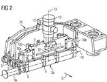
- the strand guide is composed of individual strand guide segments, such as one in Fig. 1 is shown schematically in axonometric representation.
- Each strand guide segment comprises a segment frame 1 which is formed by an outer arc segment frame 2 a and an inner arc segment frame 2 b, which are interconnected by four hydraulically actuable bracing devices 3 a, 3 b, 3 c, 3 d arranged in the corner regions of the segment frame 1, which have a predetermined positioning of Allow inner arch segment frame 2b to the outer arch segment frame 2a.
- the bearing housings 6 mounted on successively arranged cross members 4 strand guide rollers 5 can be adjusted to the degree of strand thickness or casting start on the thickness of the Anfahrstranges.
- Each strand guide roller 5 is formed as a continuous, multi-bearing roller or a plurality of aligned rollers.
- the cross members 4 are fixedly secured in the inner bow segment frame 2 b or in the outer bow segment frame 2 a.
- Fig. 2 shows in a partial section of Fig. 1 a arranged in the inner arc segment frame 2b sliding cross member 7, which carries a plurality of bearing housing 6 which receive a multi-bearing, coupled to a drive 9a strand guide roller 5a rotatably.
- a similar, driven strand guide roller 5b is disposed in the outer arch segment frame 2a opposite and in Fig. 1 indicated by the drive 9b, which is opposite to the drive 9a.
- the driven strand guide roller 5b is supported in stationary cross beams 4 in the same way as the adjacent strand guide rollers 5 fastened in the outer arc segment frame 2a (FIG. Fig. 1 ).
- the provided for the driven strand guide roller 5a sliding roller carrier 7 is on the one hand via a pivot joint 11 connected to a controllable pressure medium cylinder Anstell Sk 10, on the other hand via a pivot joint 12 on the inner arc segment frame 2b is supported.
- the two pivot joints 11, 12 define a connecting line 13, which corresponds to the line of action of the application of force to the cast strand and in FIG. 2 coincides with the central axis of the adjusting device 10.
- guides 15a, 16a are fastened on both sides to the displaceable cross member 7, which cooperate with corresponding counter guides 15b, 16b on the inner bow segment frame 2b.
- the guides 15a are arranged on the broad sides of the cross member 7, approximately at a distance of a half strand guide roller section 5c, 5e from its side edges.
- the guides 16a bear against the end faces of the cross member 7.
- the guides 15a and counter guides 15b stabilize the cross member 7 in the casting direction G, the guides 16 and counter guides 16b in the transverse direction thereto.
- the cross member 7 has a longitudinal slot 20 which is parallel to the axis of rotation 14 of the driven strand guide roller 5a and extends between the two vertical guides 15a. The adjusting forces introduced with the adjusting device 10 in the cross member are redirected through the longitudinal slot and change the voltage conditions in the cross member.
- FIG. 3 shows the movable or engageable on the cast strand cross member 7 with the mounted thereon bearing housings 6 and the rotatably supported strand guide roller 5a, which is formed in several parts and three strand guide roller sections 5c, 5d, 5e.
- the movable cross member 7 is plate-shaped and carries a series of previously described vertical guides 15a, 16a. Between the mounted in the upper edge region and the middle of the cross member 7 pivot joint 11 and the strand guide roller 5a of the cross member 7 is penetrated by a longitudinal slot 20 with a slot length L Sch .
- the slot length is shorter than the support length L St , which is determined by the edge-side end faces of the strand guide roller sections 5c, 5e.
- the slot length L Sch is also less than the support length L St formed by the strand guide roller 5a and reduced by half the length of the edge-side strand guide roller sections 5c, 5e.
- the slot length L Sch is also longer than one third of the support length L St formed by the coaxially arranged strand guide roller. It extends in an area between the two vertical guides 15a.
- the longitudinal slot 20 in the cross member 7 is at its two ends in circular extension areas 21, 21 a over.
- the diameter of these circular extension regions 21, 21 a is at least twice as large as the slot width B Sch .
- FIG. 3 two embodiments of the extension region 21, 21 a are shown.
- the extension portion 21 has a diameter larger than that Slot width B Sch .
- the extension portion 21 a has a diameter corresponding to the slot width B Sch .
- FIG. 3 illustrated embodiment of an engageable on the cast strand cross member is analogous even with a non-adjustable cross member, which is fixed rigidly in an outer arch segment frame or inner arch segment frame applicable.
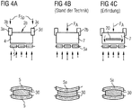
- FIG. 4a illustrates an inner arc segment frame 2b, which is braced with the outer arch segment frame, not shown, via four arranged in the corner region bracing devices 3a, 3b, 3c, 3d.
- the tension forces F Sp applied by the tensioning devices are transmitted via the cross members 4 fixedly arranged in the segment frame to the strand guide rollers 5 and thus to the cast strand 30.
- This is a desired shape per se, which ensures centered strand transport in the continuous casting plant.
- FIG. 4b For the special case of a displaceable in the segment frame guided and engageable with a central contact force F A against the cast strand cross member 7, which is formed according to the prior art without a longitudinal slot, sets a deformation image, as shown in FIG. 4b is shown schematically.
- the central contact force leads to a deflection of the adjustable cross member 7 and supported on it strand guide rollers 5a. This deflection is transmitted to the cast strand and therefore leads inside the bow to a concave deformation of the cast strand 30 and may increase the bow outer side convex strand deformation.
- the longitudinal slot according to the invention can be arranged on any strand guide rollers carrying cross members both on the outer bow and on the inner bow of the strand guide. This possibility exists regardless of whether this cross member is rigidly anchored in a strand guide segment, as inner arc segment part is adjustable or designed as an individual component in the strand guide segment with a cross member associated Anstell issued adjustable.
- the strand guide segment can also comprise only one cross member carrying at least one strand guide roller.
Landscapes
- Engineering & Computer Science (AREA)
- Mechanical Engineering (AREA)
- Continuous Casting (AREA)
Abstract
Claims (10)
- Segment de guidage de barre coulée pour le soutien et le guidage d'une barre métallique coulée dans un guidage de barre coulée d'une installation de coulée continue, avec une pluralité de rouleaux de guidage de barre coulée (5, 5a, 5b), qui sont appuyés sur des traverses (4, 7) dans un châssis de segment (1) du segment de guidage de barre coulée, dans lequel au moins une des traverses (7) est réalisée en forme de plaque, caractérisé en ce qu'au moins une traverse (7) présente une fente longitudinale (20) orientée parallèlement à l'extension longitudinale du rouleau de guidage de barre coulée (5a).
- Segment de guidage de barre coulée selon la revendication 1, caractérisé en ce qu'au moins une traverse (7) portant un rouleau de guidage de barre coulée (5a) est déplaçable dans le châssis de segment (1) normalement à la direction de l'extension longitudinale du rouleau de guidage de barre coulée (5a), cette traverse déplaçable (7) est reliée au châssis de segment (1) par au moins un dispositif de réglage (10) et la traverse déplaçable (7) est réalisée en forme de plaque et présente une fente longitudinale (20) orientée parallèlement à l'extension longitudinale du rouleau de guidage de barre coulée (5a).
- Segment de guidage de barre coulée selon la revendication 2, caractérisé en ce que la fente longitudinale (20) dans la traverse (7) est disposée entre une articulation pivotante (11) de l'articulation du dispositif de réglage (10) sur la traverse (7) et le rouleau de guidage de barre coulée (5a).
- Segment de guidage de barre coulée selon l'une quelconque des revendications précédentes, caractérisé en ce que la fente longitudinale (20) dans la traverse (7) présente une longueur de fente (LSch), qui est plus petite qu'une longueur d'appui (Lst) formée par le rouleau de guidage de barre coulée (5a) disposé coaxialement et appuyé sur cette traverse (7).
- Segment de guidage de barre coulée selon l'une quelconque des revendications 1 à 3, caractérisé en ce que la fente longitudinale (20) dans la traverse (7) présente une longueur de fente (LSch), qui est plus petite qu'une longueur d'appui (LSt) formée par le rouleau de guidage de barre coulée (5a) disposé coaxialement et appuyé sur cette traverse (7) et diminuée de la moitié de la longueur des parties de rouleau de guidage de barre coulée (5c, 5e) situées du côté des bords.
- Segment de guidage de barre coulée selon l'une quelconque des revendications 1 à 3, caractérisé en ce que la fente longitudinale (20) dans la traverse (7) s'étend entre deux guides (15a) orientés normalement à l'extension longitudinale du rouleau de guidage de barre coulée (5a).
- Segment de guidage de barre coulée selon l'une quelconque des revendications précédentes, caractérisé en ce que la fente longitudinale (20) dans la traverse (7) présente une longueur de fente (LSch), qui est plus grande qu'un tiers de la longueur d'appui (LSt) formée par le rouleau de guidage de barre coulée (5a) disposé coaxialement et appuyé sur cette traverse (7).
- Segment de guidage de barre coulée selon l'une quelconque des revendications 2 à 7, caractérisé en ce que le dispositif de réglage (10) reliant la traverse (7) au châssis de segment (1) présente une ligne d'action de l'application de force qui coupe au milieu la longueur de fente (LSch) de la fente longitudinale (20) dans la traverse (7) et la longueur d'appui (LSt) formée par le rouleau de guidage de barre coulée (5a).
- Segment de guidage de barre coulée selon l'une quelconque des revendications précédentes, caractérisé en ce que la fente longitudinale (20) dans la traverse (7) présente à ses extrémités des zones élargies (21, 21a).
- Segment de guidage de barre coulée selon la revendication 9, caractérisé en ce que les zones élargies d'extrémité (21, 21a) sont réalisées en forme de cercle et le diamètre des zones élargies de forme circulaire (21, 21a) est égal ou supérieur à la largeur de fente (BSch) de la fente longitudinale (20).
Applications Claiming Priority (2)
| Application Number | Priority Date | Filing Date | Title |
|---|---|---|---|
| AT0049208A AT506549B1 (de) | 2008-03-28 | 2008-03-28 | Strangführungssegment |
| PCT/EP2009/052099 WO2009118222A1 (fr) | 2008-03-28 | 2009-02-23 | Segment de guidage de barre coulée |
Publications (2)
| Publication Number | Publication Date |
|---|---|
| EP2257397A1 EP2257397A1 (fr) | 2010-12-08 |
| EP2257397B1 true EP2257397B1 (fr) | 2012-04-04 |
Family
ID=40602489
Family Applications (1)
| Application Number | Title | Priority Date | Filing Date |
|---|---|---|---|
| EP09724438A Not-in-force EP2257397B1 (fr) | 2008-03-28 | 2009-02-23 | Segment de guidage de barre coulée |
Country Status (5)
| Country | Link |
|---|---|
| EP (1) | EP2257397B1 (fr) |
| KR (1) | KR20100126846A (fr) |
| CN (1) | CN102083571A (fr) |
| AT (2) | AT506549B1 (fr) |
| WO (1) | WO2009118222A1 (fr) |
Cited By (1)
| Publication number | Priority date | Publication date | Assignee | Title |
|---|---|---|---|---|
| EP4529998A1 (fr) * | 2023-09-27 | 2025-04-02 | SMS group GmbH | Segment adaptatif d'un guidage de barre, notamment pour une installation de coulée continue |
Families Citing this family (12)
| Publication number | Priority date | Publication date | Assignee | Title |
|---|---|---|---|---|
| DE102010007660B4 (de) * | 2010-01-12 | 2023-06-01 | Sms Group Gmbh | Stranggießmaschine |
| AT509352B1 (de) * | 2010-02-05 | 2014-06-15 | Siemens Vai Metals Tech Gmbh | Strangführungssegment in kassettenbauweise mit einzelrollenanstellung |
| EP2404686A1 (fr) * | 2010-07-09 | 2012-01-11 | Siemens VAI Metals Technologies GmbH | Support de rouleaux pour un segment de guidage de ligne d'une machine de coulée |
| DE102011088127A1 (de) * | 2011-06-07 | 2012-12-13 | Sms Siemag Ag | Strangführungssegment einer Strangführung einer Stranggießanlage und Verfahren zum Betreiben eines Strangführungssegments |
| KR101372640B1 (ko) * | 2011-12-27 | 2014-03-11 | 주식회사 포스코 | 분리형 세그먼트 및 이를 이용한 롤 교환 방법 |
| CN104057049B (zh) * | 2014-07-09 | 2016-06-15 | 北京科技大学 | 连铸坯凝固末端大压下的连铸机扇形段及其大压下方法 |
| CN104057050B (zh) * | 2014-07-14 | 2016-04-13 | 北京科技大学 | 一种板坯连铸机扇形段连铸辊的支撑结构 |
| AT516412B1 (de) * | 2014-10-28 | 2017-07-15 | Primetals Technologies Austria GmbH | Strangführungsrolleneinheit für eine Stranggießmaschine |
| CN108015244B (zh) * | 2017-12-05 | 2023-11-14 | 马鞍山钢铁股份有限公司 | 一种连铸机扇形段结构 |
| AT521416B1 (de) * | 2018-07-02 | 2024-01-15 | Primetals Technologies Austria GmbH | Strangführungssegment mit individuell verschiebbaren Strangführungsrollen |
| CN110523938B (zh) * | 2019-07-24 | 2021-10-01 | 中国一冶集团有限公司 | 一种连铸机更换导轨墙面固定装置及更换导轨固定的方法 |
| CN115647318A (zh) * | 2022-09-20 | 2023-01-31 | 山东钢铁集团日照有限公司 | 一种连铸扇形段辊缝控制装置及其控制方法 |
Family Cites Families (8)
| Publication number | Priority date | Publication date | Assignee | Title |
|---|---|---|---|---|
| GB1101959A (en) * | 1965-07-20 | 1968-02-07 | Nat Res Dev | Improvements in and relating to load cells |
| DE59912592D1 (de) * | 1998-03-09 | 2006-02-09 | Sms Demag Ag | Führungselement einer Stranggiessanlage |
| DE19916173A1 (de) * | 1999-04-10 | 2000-10-12 | Sms Demag Ag | Verfahren und Vorrichtung zum Einstellen des Brammenprofils einer stranggegossenen Bramme, insbesondere einer Dünnbramme |
| AT3953U3 (de) * | 2000-06-02 | 2001-04-25 | Voest Alpine Ind Anlagen | Strangführungselement und strangführungssegment mit integriertem strangführungselement |
| DE10040271A1 (de) * | 2000-08-17 | 2002-02-28 | Sms Demag Ag | Vorrichtung zum Stranggießen von Metallen, insbesondere von Stahl |
| AT409465B (de) * | 2000-12-12 | 2002-08-26 | Voest Alpine Ind Anlagen | Verfahren zum einstellen eines giessspaltes an einer strangführung einer stranggiessanlage |
| DE102004048618A1 (de) * | 2004-10-06 | 2006-04-13 | Sms Demag Ag | Verfahren und Rollensegment zum Bestimmen der Kernerstarrung und/oder der Sumpfspitze beim Stranggießen von Metallen, insbesondere von Stahlwerkstoffen |
| DE102006040012A1 (de) * | 2006-08-25 | 2008-02-28 | Sms Demag Ag | Strangführungseinrichtung und Verfahren zum Führen eines noch nicht durcherstarrten Metallbandes |
-
2008
- 2008-03-28 AT AT0049208A patent/AT506549B1/de not_active IP Right Cessation
-
2009
- 2009-02-23 EP EP09724438A patent/EP2257397B1/fr not_active Not-in-force
- 2009-02-23 AT AT09724438T patent/ATE552057T1/de active
- 2009-02-23 CN CN2009801193193A patent/CN102083571A/zh active Pending
- 2009-02-23 WO PCT/EP2009/052099 patent/WO2009118222A1/fr not_active Ceased
- 2009-02-23 KR KR1020107024086A patent/KR20100126846A/ko not_active Ceased
Cited By (1)
| Publication number | Priority date | Publication date | Assignee | Title |
|---|---|---|---|---|
| EP4529998A1 (fr) * | 2023-09-27 | 2025-04-02 | SMS group GmbH | Segment adaptatif d'un guidage de barre, notamment pour une installation de coulée continue |
Also Published As
| Publication number | Publication date |
|---|---|
| EP2257397A1 (fr) | 2010-12-08 |
| CN102083571A (zh) | 2011-06-01 |
| ATE552057T1 (de) | 2012-04-15 |
| KR20100126846A (ko) | 2010-12-02 |
| WO2009118222A1 (fr) | 2009-10-01 |
| AT506549A1 (de) | 2009-10-15 |
| AT506549B1 (de) | 2011-06-15 |
Similar Documents
| Publication | Publication Date | Title |
|---|---|---|
| EP2257397B1 (fr) | Segment de guidage de barre coulée | |
| DE2501956C2 (de) | Vorrichtung zum Stützen, Führen, Biegen bzw. Richten und Verformen eines breiten Gußstranges | |
| EP1289689B1 (fr) | Element de guidage de barre coulee | |
| EP1043095B1 (fr) | Dispositif pour régler le profil d'une brame coulée en continue, en particulier d'une brame mince | |
| EP2056981A1 (fr) | Dispositif de guidage de barre et procédé de guidage d'un feuillard métallique encore non durci à c ur | |
| EP2342026B1 (fr) | Dispositif de laminage | |
| AT406644B (de) | Präzisionswalzverfahren | |
| DE102008009136A1 (de) | Strangführung, insbesondere für eine Stahlbrammen-Stranggießanlage | |
| DE1558220C3 (de) | Lagerung von Walzen für die Formänderung eines aus einer Stranggießkokille kommenden metallischen Stranges | |
| EP1365874B1 (fr) | Procede et dispositif de fabrication de brames minces | |
| EP3256276B1 (fr) | Installation de coulage | |
| EP1132161A1 (fr) | Procédé pour la coulée continue de brames, en particulier de brames minces | |
| DE3034444A1 (de) | Richttreiber in einer stahlstranggiessanlage | |
| DE2939321C2 (fr) | ||
| WO2006056423A1 (fr) | Dispositif et procede de coulee continue | |
| EP1960136A1 (fr) | Procede de coulee continue de minces feuillards metalliques et installation de coulee continue | |
| EP0184025A2 (fr) | Dispositif de guidage sur les bandes de coulée d'une lingotière de coulée continue à bande double | |
| EP0203279B1 (fr) | Cylindre, de préférence cylindre de contre-pression d'un cylindre gravé dont la chemise peut être courbée | |
| EP0941787A1 (fr) | Element support pour une installation de coulée continue | |
| WO2002013994A1 (fr) | Dispositif de coulee continue de metaux, notamment d'acier | |
| EP3235579B1 (fr) | Dispositif de guidage de barre et procédé destiné à supporter une barre de coulée | |
| DE10145106A1 (de) | Walzgutführungseinrichtung für Horizontal-Duowalzgerüste | |
| AT234932B (de) | Stützwalzengerüst zur Führung eines gebogenen Gießstranges in einer Stahl- oder Metallstranggießanlage | |
| AT347615B (de) | Treibwalzengeruest fuer mehrstrangige stranggussanlagen | |
| AT251783B (de) | Strangführung für eine Stranggußanlage |
Legal Events
| Date | Code | Title | Description |
|---|---|---|---|
| PUAI | Public reference made under article 153(3) epc to a published international application that has entered the european phase |
Free format text: ORIGINAL CODE: 0009012 |
|
| 17P | Request for examination filed |
Effective date: 20100922 |
|
| AK | Designated contracting states |
Kind code of ref document: A1 Designated state(s): AT BE BG CH CY CZ DE DK EE ES FI FR GB GR HR HU IE IS IT LI LT LU LV MC MK MT NL NO PL PT RO SE SI SK TR |
|
| AX | Request for extension of the european patent |
Extension state: AL BA RS |
|
| DAX | Request for extension of the european patent (deleted) | ||
| GRAP | Despatch of communication of intention to grant a patent |
Free format text: ORIGINAL CODE: EPIDOSNIGR1 |
|
| GRAS | Grant fee paid |
Free format text: ORIGINAL CODE: EPIDOSNIGR3 |
|
| GRAA | (expected) grant |
Free format text: ORIGINAL CODE: 0009210 |
|
| AK | Designated contracting states |
Kind code of ref document: B1 Designated state(s): AT BE BG CH CY CZ DE DK EE ES FI FR GB GR HR HU IE IS IT LI LT LU LV MC MK MT NL NO PL PT RO SE SI SK TR |
|
| REG | Reference to a national code |
Ref country code: GB Ref legal event code: FG4D Free format text: NOT ENGLISH |
|
| REG | Reference to a national code |
Ref country code: CH Ref legal event code: EP |
|
| REG | Reference to a national code |
Ref country code: AT Ref legal event code: REF Ref document number: 552057 Country of ref document: AT Kind code of ref document: T Effective date: 20120415 |
|
| REG | Reference to a national code |
Ref country code: IE Ref legal event code: FG4D Free format text: LANGUAGE OF EP DOCUMENT: GERMAN |
|
| REG | Reference to a national code |
Ref country code: DE Ref legal event code: R096 Ref document number: 502009003205 Country of ref document: DE Effective date: 20120606 |
|
| REG | Reference to a national code |
Ref country code: NL Ref legal event code: VDEP Effective date: 20120404 |
|
| LTIE | Lt: invalidation of european patent or patent extension |
Effective date: 20120404 |
|
| PG25 | Lapsed in a contracting state [announced via postgrant information from national office to epo] |
Ref country code: PL Free format text: LAPSE BECAUSE OF FAILURE TO SUBMIT A TRANSLATION OF THE DESCRIPTION OR TO PAY THE FEE WITHIN THE PRESCRIBED TIME-LIMIT Effective date: 20120404 Ref country code: SE Free format text: LAPSE BECAUSE OF FAILURE TO SUBMIT A TRANSLATION OF THE DESCRIPTION OR TO PAY THE FEE WITHIN THE PRESCRIBED TIME-LIMIT Effective date: 20120404 Ref country code: CY Free format text: LAPSE BECAUSE OF FAILURE TO SUBMIT A TRANSLATION OF THE DESCRIPTION OR TO PAY THE FEE WITHIN THE PRESCRIBED TIME-LIMIT Effective date: 20120404 Ref country code: FI Free format text: LAPSE BECAUSE OF FAILURE TO SUBMIT A TRANSLATION OF THE DESCRIPTION OR TO PAY THE FEE WITHIN THE PRESCRIBED TIME-LIMIT Effective date: 20120404 Ref country code: NO Free format text: LAPSE BECAUSE OF FAILURE TO SUBMIT A TRANSLATION OF THE DESCRIPTION OR TO PAY THE FEE WITHIN THE PRESCRIBED TIME-LIMIT Effective date: 20120704 Ref country code: SI Free format text: LAPSE BECAUSE OF FAILURE TO SUBMIT A TRANSLATION OF THE DESCRIPTION OR TO PAY THE FEE WITHIN THE PRESCRIBED TIME-LIMIT Effective date: 20120404 Ref country code: LT Free format text: LAPSE BECAUSE OF FAILURE TO SUBMIT A TRANSLATION OF THE DESCRIPTION OR TO PAY THE FEE WITHIN THE PRESCRIBED TIME-LIMIT Effective date: 20120404 Ref country code: IS Free format text: LAPSE BECAUSE OF FAILURE TO SUBMIT A TRANSLATION OF THE DESCRIPTION OR TO PAY THE FEE WITHIN THE PRESCRIBED TIME-LIMIT Effective date: 20120804 |
|
| PG25 | Lapsed in a contracting state [announced via postgrant information from national office to epo] |
Ref country code: HR Free format text: LAPSE BECAUSE OF FAILURE TO SUBMIT A TRANSLATION OF THE DESCRIPTION OR TO PAY THE FEE WITHIN THE PRESCRIBED TIME-LIMIT Effective date: 20120404 Ref country code: PT Free format text: LAPSE BECAUSE OF FAILURE TO SUBMIT A TRANSLATION OF THE DESCRIPTION OR TO PAY THE FEE WITHIN THE PRESCRIBED TIME-LIMIT Effective date: 20120806 Ref country code: LV Free format text: LAPSE BECAUSE OF FAILURE TO SUBMIT A TRANSLATION OF THE DESCRIPTION OR TO PAY THE FEE WITHIN THE PRESCRIBED TIME-LIMIT Effective date: 20120404 Ref country code: GR Free format text: LAPSE BECAUSE OF FAILURE TO SUBMIT A TRANSLATION OF THE DESCRIPTION OR TO PAY THE FEE WITHIN THE PRESCRIBED TIME-LIMIT Effective date: 20120705 |
|
| PG25 | Lapsed in a contracting state [announced via postgrant information from national office to epo] |
Ref country code: NL Free format text: LAPSE BECAUSE OF FAILURE TO SUBMIT A TRANSLATION OF THE DESCRIPTION OR TO PAY THE FEE WITHIN THE PRESCRIBED TIME-LIMIT Effective date: 20120404 Ref country code: CZ Free format text: LAPSE BECAUSE OF FAILURE TO SUBMIT A TRANSLATION OF THE DESCRIPTION OR TO PAY THE FEE WITHIN THE PRESCRIBED TIME-LIMIT Effective date: 20120404 Ref country code: DK Free format text: LAPSE BECAUSE OF FAILURE TO SUBMIT A TRANSLATION OF THE DESCRIPTION OR TO PAY THE FEE WITHIN THE PRESCRIBED TIME-LIMIT Effective date: 20120404 Ref country code: EE Free format text: LAPSE BECAUSE OF FAILURE TO SUBMIT A TRANSLATION OF THE DESCRIPTION OR TO PAY THE FEE WITHIN THE PRESCRIBED TIME-LIMIT Effective date: 20120404 Ref country code: SK Free format text: LAPSE BECAUSE OF FAILURE TO SUBMIT A TRANSLATION OF THE DESCRIPTION OR TO PAY THE FEE WITHIN THE PRESCRIBED TIME-LIMIT Effective date: 20120404 Ref country code: RO Free format text: LAPSE BECAUSE OF FAILURE TO SUBMIT A TRANSLATION OF THE DESCRIPTION OR TO PAY THE FEE WITHIN THE PRESCRIBED TIME-LIMIT Effective date: 20120404 |
|
| PLBE | No opposition filed within time limit |
Free format text: ORIGINAL CODE: 0009261 |
|
| STAA | Information on the status of an ep patent application or granted ep patent |
Free format text: STATUS: NO OPPOSITION FILED WITHIN TIME LIMIT |
|
| 26N | No opposition filed |
Effective date: 20130107 |
|
| PG25 | Lapsed in a contracting state [announced via postgrant information from national office to epo] |
Ref country code: ES Free format text: LAPSE BECAUSE OF FAILURE TO SUBMIT A TRANSLATION OF THE DESCRIPTION OR TO PAY THE FEE WITHIN THE PRESCRIBED TIME-LIMIT Effective date: 20120715 |
|
| REG | Reference to a national code |
Ref country code: DE Ref legal event code: R097 Ref document number: 502009003205 Country of ref document: DE Effective date: 20130107 |
|
| PG25 | Lapsed in a contracting state [announced via postgrant information from national office to epo] |
Ref country code: BG Free format text: LAPSE BECAUSE OF FAILURE TO SUBMIT A TRANSLATION OF THE DESCRIPTION OR TO PAY THE FEE WITHIN THE PRESCRIBED TIME-LIMIT Effective date: 20120704 |
|
| BERE | Be: lapsed |
Owner name: SIEMENS VAI METALS TECHNOLOGIES GMBH Effective date: 20130228 |
|
| PG25 | Lapsed in a contracting state [announced via postgrant information from national office to epo] |
Ref country code: MC Free format text: LAPSE BECAUSE OF NON-PAYMENT OF DUE FEES Effective date: 20130228 |
|
| REG | Reference to a national code |
Ref country code: CH Ref legal event code: PL |
|
| GBPC | Gb: european patent ceased through non-payment of renewal fee |
Effective date: 20130223 |
|
| PG25 | Lapsed in a contracting state [announced via postgrant information from national office to epo] |
Ref country code: CH Free format text: LAPSE BECAUSE OF NON-PAYMENT OF DUE FEES Effective date: 20130228 Ref country code: LI Free format text: LAPSE BECAUSE OF NON-PAYMENT OF DUE FEES Effective date: 20130228 |
|
| REG | Reference to a national code |
Ref country code: FR Ref legal event code: ST Effective date: 20131031 |
|
| REG | Reference to a national code |
Ref country code: IE Ref legal event code: MM4A |
|
| PG25 | Lapsed in a contracting state [announced via postgrant information from national office to epo] |
Ref country code: IE Free format text: LAPSE BECAUSE OF NON-PAYMENT OF DUE FEES Effective date: 20130223 Ref country code: BE Free format text: LAPSE BECAUSE OF NON-PAYMENT OF DUE FEES Effective date: 20130228 Ref country code: FR Free format text: LAPSE BECAUSE OF NON-PAYMENT OF DUE FEES Effective date: 20130228 Ref country code: GB Free format text: LAPSE BECAUSE OF NON-PAYMENT OF DUE FEES Effective date: 20130223 |
|
| PG25 | Lapsed in a contracting state [announced via postgrant information from national office to epo] |
Ref country code: MT Free format text: LAPSE BECAUSE OF FAILURE TO SUBMIT A TRANSLATION OF THE DESCRIPTION OR TO PAY THE FEE WITHIN THE PRESCRIBED TIME-LIMIT Effective date: 20120404 |
|
| PGFP | Annual fee paid to national office [announced via postgrant information from national office to epo] |
Ref country code: DE Payment date: 20140417 Year of fee payment: 6 |
|
| REG | Reference to a national code |
Ref country code: AT Ref legal event code: MM01 Ref document number: 552057 Country of ref document: AT Kind code of ref document: T Effective date: 20140223 |
|
| PGFP | Annual fee paid to national office [announced via postgrant information from national office to epo] |
Ref country code: IT Payment date: 20150228 Year of fee payment: 7 |
|
| PG25 | Lapsed in a contracting state [announced via postgrant information from national office to epo] |
Ref country code: AT Free format text: LAPSE BECAUSE OF NON-PAYMENT OF DUE FEES Effective date: 20140223 |
|
| PG25 | Lapsed in a contracting state [announced via postgrant information from national office to epo] |
Ref country code: TR Free format text: LAPSE BECAUSE OF FAILURE TO SUBMIT A TRANSLATION OF THE DESCRIPTION OR TO PAY THE FEE WITHIN THE PRESCRIBED TIME-LIMIT Effective date: 20120404 |
|
| PG25 | Lapsed in a contracting state [announced via postgrant information from national office to epo] |
Ref country code: MK Free format text: LAPSE BECAUSE OF FAILURE TO SUBMIT A TRANSLATION OF THE DESCRIPTION OR TO PAY THE FEE WITHIN THE PRESCRIBED TIME-LIMIT Effective date: 20120404 Ref country code: HU Free format text: LAPSE BECAUSE OF FAILURE TO SUBMIT A TRANSLATION OF THE DESCRIPTION OR TO PAY THE FEE WITHIN THE PRESCRIBED TIME-LIMIT; INVALID AB INITIO Effective date: 20090223 Ref country code: LU Free format text: LAPSE BECAUSE OF NON-PAYMENT OF DUE FEES Effective date: 20130223 |
|
| REG | Reference to a national code |
Ref country code: DE Ref legal event code: R119 Ref document number: 502009003205 Country of ref document: DE |
|
| PG25 | Lapsed in a contracting state [announced via postgrant information from national office to epo] |
Ref country code: DE Free format text: LAPSE BECAUSE OF NON-PAYMENT OF DUE FEES Effective date: 20150901 |
|
| PG25 | Lapsed in a contracting state [announced via postgrant information from national office to epo] |
Ref country code: IT Free format text: LAPSE BECAUSE OF NON-PAYMENT OF DUE FEES Effective date: 20160223 |