EP2254347A2 - Lautsprechervorrichtung - Google Patents
Lautsprechervorrichtung Download PDFInfo
- Publication number
- EP2254347A2 EP2254347A2 EP10163469A EP10163469A EP2254347A2 EP 2254347 A2 EP2254347 A2 EP 2254347A2 EP 10163469 A EP10163469 A EP 10163469A EP 10163469 A EP10163469 A EP 10163469A EP 2254347 A2 EP2254347 A2 EP 2254347A2
- Authority
- EP
- European Patent Office
- Prior art keywords
- protection
- unit
- enclosure
- protection unit
- speaker
- Prior art date
- Legal status (The legal status is an assumption and is not a legal conclusion. Google has not performed a legal analysis and makes no representation as to the accuracy of the status listed.)
- Withdrawn
Links
Images



Classifications
-
- H—ELECTRICITY
- H04—ELECTRIC COMMUNICATION TECHNIQUE
- H04R—LOUDSPEAKERS, MICROPHONES, GRAMOPHONE PICK-UPS OR LIKE ACOUSTIC ELECTROMECHANICAL TRANSDUCERS; ELECTRIC HEARING AIDS; PUBLIC ADDRESS SYSTEMS
- H04R1/00—Details of transducers, loudspeakers or microphones
- H04R1/20—Arrangements for obtaining desired frequency or directional characteristics
- H04R1/32—Arrangements for obtaining desired frequency or directional characteristics for obtaining desired directional characteristic only
- H04R1/34—Arrangements for obtaining desired frequency or directional characteristics for obtaining desired directional characteristic only by using a single transducer with sound reflecting, diffracting, directing or guiding means
- H04R1/345—Arrangements for obtaining desired frequency or directional characteristics for obtaining desired directional characteristic only by using a single transducer with sound reflecting, diffracting, directing or guiding means for loudspeakers
Definitions
- the present invention relates to a cover that protects a speaker unit included in a speaker apparatus.
- the outer surface of the enclosure is preferable for the outer surface of the enclosure to be smooth during use, in order to improve the quality of the sound output from the speaker unit.
- the speaker unit By mounting the speaker unit in an opening portion of the enclosure and inputting an electrical signal thereto, or providing corner portions of the enclosure with tapered portions, it is possible to suppress the level of sound waves that are generated due to the sound radiated from the speaker unit being diffracted by the corner portions of the enclosure.
- the speaker is covered in order to prevent it from, for example, becoming damaged or dirty, the outer surface of the enclosure ends up having unevenness, which adversely influences the sound quality.
- the speaker unit is mounted on a face that is recessed by one level, and a shutter is placed inside the speaker enclosure.
- the shutter is configured so as to be able to move along the front lateral face, top lateral face, and back lateral face of the speaker enclosure.
- the shutter can move toward the back of the speaker unit so as to expose the speaker unit when the radio/cassette apparatus is used.
- shutter-supporting members and the like protrude out farther than the face to which the speaker unit is mounted, there is the disadvantage that the sound radiated from the speaker unit is diffracted by the edge lines of the shutter-supporting members and the like, which influences the sound quality.
- the present invention provides a speaker apparatus in which the speaker is open during use, and a speaker is protected during non-use, whilst minimizing the occurrence of sound diffraction, and with minimal influence on the sound quality.
- the present invention in its aspect provides a speaker apparatus as specified in claims 1 to 13.
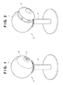
- FIG. 1 is a perspective diagram showing an open position of a protection unit in a speaker apparatus having a protection unit according to Embodiment 1.
- FIG. 2 is a perspective diagram showing a closed position of a protection unit in the speaker apparatus having a protection unit according to Embodiment 1.
- FIG. 3 is a perspective diagram showing the protection unit according to Embodiment 1.
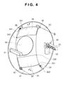
- FIG. 4 is a schematic diagram showing the protection unit in the open position according to Embodiment 1.
- FIG. 5 is a schematic diagram showing the protection unit in the closed position according to Embodiment 1.
- FIG. 6 is a detailed view of a portion V in FIG. 3 according to Embodiment 1.
- FIG. 7 is a cross-sectional view taken along W-W in FIG. 3 according to Embodiment 1.
- FIG. 8 is a perspective diagram showing an open position of a protection unit in a speaker apparatus having protection units according to Embodiment 2.
- FIG. 9 is a perspective diagram showing a closed position of a protection unit in the speaker apparatus having protection units according to Embodiment 2.
- FIG. 10 is a schematic diagram showing a protection unit in the closed position according to Embodiment 2.
- FIG. 11 is a schematic diagram showing the protection unit during operational movement from the open position to the closed position according to Embodiment 2.
- FIG. 12 is a schematic diagram showing the protection unit in the closed position according to Embodiment 2.
- FIG. 13 is a schematic diagram showing a protection unit in an open position according to Embodiment 3.
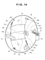
- FIG. 14 is a schematic diagram showing the protection unit in a closed position according to Embodiment 3.
- FIG. 1 is a perspective diagram showing a protection unit open position in a speaker apparatus having a protection unit according to Embodiment 1 of the present invention.
- FIG. 2 is a perspective diagram showing a protection unit closed position in the speaker apparatus shown in FIG. 1 .
- a speaker apparatus 5 having a protection unit 3 of the present embodiment includes a spherical enclosure 1 in which a speaker unit 2 is contained, and the speaker unit 2 contained in the enclosure 1.
- the speaker apparatus 5 further includes the protection unit 3 that covers the speaker unit 2, and a speaker stand 4 that places at ear level the enclosure 1 in which the speaker unit 2 is mounted.
- the protection unit 3 forms a portion of the outer surface of the enclosure 1 so as to reduce the occurrence of the diffraction of sound output from the speaker unit to the exterior when the protection unit 3 is in an open position.
- the protection unit 3 has a mechanism that enables the distance to the enclosure 1 to be variable (so the protection unit can be moved away from the enclosure, towards the exterior, and back towards the enclosure), and the opening state of an opening portion can be controlled by such mechanism.
- the protection unit 3 when in a closed position, the protection unit 3 has moved forward and changed the opening state of the opening portion, and covers the speaker unit 2, thus protecting the speaker unit 2.
- FIG. 3 is a perspective diagram showing the protection unit according to Embodiment 1 of the present invention. The following describes a configuration of the protection unit with reference to FIG. 3 .
- the protection unit 3 has a protection cover 30 that forms a portion of the outer surface of the enclosure, and the protection unit 3 is supported by the enclosure 1 shown in FIG. 1 via a support member 31 and a rack-provided support member 32 (so a support member provided with a rack) that are mounted to the protection cover 30, which has an opening (portion) 44.
- the rack-provided support member 32 is engaged with a gear-provided motor 33 (so a motor provided with a pinion), and is mounted inside the enclosure 1.
- the protection unit 3 has protection members 34 and 35 that can cover the speaker unit 2 (by substantially or wholly covering the opening 44).
- the protection members 34 and 35 are guided by guide members 36 and 37 so as to be able to move from the open position to the closed position.
- the guide portion is bilaterally symmetrical, and therefore only the configuration of one side of the guide portion will be described in detail.
- FIG. 4 is a schematic diagram showing the protection unit in the open position. Although the guide members 36 and 37 shown in FIG. 3 have been omitted for convenience from FIG. 4 , details of the guide members are illustrated in FIGS. 6 and 7 .
- FIG. 5 is a schematic diagram showing the protection unit in the closed position.
- FIG. 6 is a diagram showing details of a portion V in FIG. 3 , that is to say, a diagram showing details of the guide portion.
- FIG. 7 is a cross-sectional diagram showing details of a portion along W-W in FIG. 3 , that is to say, a diagram showing details of the guide portion.
- FIG. 7 shows one side of the protection member 34. The following describes portions of the protection unit with reference to FIGS. 4 to 7 .
- the guide member 37 has a recessed portion that guides rollers 343 and 344, and a groove that guides a connecting means, in particular wire 41.
- the rollers 343 and 344 are rotatably mounted to a lateral face of the protection member 34, and are guided by the recessed portion of the guide member 37.
- the wire 41 is guided by the groove of the guide member 37 shown in Fig. 7 .
- the guide member 36 shown in FIG. 3 has a similar configuration to that of the guide member 37.
- end portions of biasing means, in particular springs 38 and 39 on one side are locked to spring holding means, in particular pins 341 and 351, that are implanted in the protection members 34 and 35, and thus the spring holding pins 341 and 351 are biased in the direction toward the open position.
- the springs 38 and 39 are supported by spring holding pins 301 and 302 that are implanted in the protection cover 30.
- the two ends of an elongate connecting means, in particular wire 40 are respectively locked to a wire holding means, in particular a pin 352 that is implanted in the protection member 35 and to the inner side (not shown) of the enclosure 1.
- the two ends of the elongate connecting means, in particular wire 41 are respectively locked to a holding means for holding the wire, in particular a pin 342 that is implanted in the protection member 34 and to the inner side (not shown) of the enclosure.
- the wires 40 and 41 are guided by guide means, in particular the grooves of the guide members 36 and 37, and are locked as described above via pulleys 42 and 43.
- the pulleys 42 and 43 have grooves to which the wires 40 and 41 are caused to fit in, and the pulleys 42 and 43 are connected to the protection cover 30 such that they can rotate.
- FIG. 1 shows a protection unit open position in the speaker apparatus 5 having the protection unit 3 according to Embodiment 1
- FIG. 4 shows the protection unit 3 in the open position.
- the protection unit 3 When the protection unit 3 is in the open position, at respective ends of the protection members 34 and 35, the spring holding pins 341 and 351 of the protection members 34 and 35 are biased by the springs 38 and 39, and thus the protection members 34 and 35 are biased in the directions of arrows A and B respectively. At the other respective ends of the protection members 34 and 35, the wire holding pins 342 and 352 of the protection members 34 and 35 are locked by the wires 40 and 41. According to this configuration, the protection members 34 and 35 are at rest at positions at which a balance is achieved between the biasing force of the springs 38 and 39 and the tensile force of the wires 40 and 41, that is to say, open positions. In the state in which the protection unit 3 is in the open position shown in FIG. 4 , the protection unit 3 forms a portion of the outer surface of the enclosure shown in FIG. 1 .
- the gear-provided motor 33 rotates in the direction of an arrow C
- the rotational movement of the gear-provided motor 33 is transmitted to the rack-provided support member 32 via the gear and the rack
- the rack-provided support member 32 thus moves in the direction of an arrow D (so in a direction away from the enclosure and towards the exterior).
- the protection unit 3 moves forward with respect to the speaker unit 2 (and with respect to the enclosure 1).
- the wires 40 and 41 that are locked to the inner side of the enclosure 1 and to the protection members 34 and 35 have a constant length.
- the protection unit 3 moves forward, there is an increase in the distance between the positions where the wires 40 and 41 are locked to the inner side of the enclosure 1 and the positions where the pulleys 42 and 43 are placed. As a result, there is a decrease in the distance between the positions where the wires 40 and 41 are locked to the wire holding pins 342 and 352 of the protection members 34 and 35 and the positions where the pulleys 42 and 43 are placed. Accordingly, the protection members 34 and 35 of the protection unit 3 move in directions opposite to the arrows A and B respectively, that is to say, in directions for covering the opening portion 44 of the protection cover 30.
- the distance that the protection unit 3 moves and the distance that the protection members 34 and 35 move when moving from the open position to the closed position are set to the same length. Accordingly, when the movement of the protection unit 3 is complete, the protection members 34 and 35 have moved to positions at which they completely cover the opening (portion) 44 of the protection cover 30. Such movement realizes the state of the protection unit 3 in the closed position shown in FIG. 5 , and enables protecting the speaker unit 2 as shown in FIG. 2 .
- FIG. 2 shows the closed position of the protection unit in the speaker apparatus 5 having the protection unit 3 according to Embodiment 1 of the present invention. Also, FIG. 5 shows the protection unit 3 in the closed position.
- the gear-provided motor 33 rotates in the direction of an arrow R, the rotational movement of the gear-provided motor 33 is transmitted to the rack-provided support member 32 via the gear and the rack, and thus the rack-provided support member 32 moves in the direction of an arrow S.
- the protection unit 3 therefore moves in a direction for approaching the speaker unit 2.
- the wires 40 and 41 that are locked to the inner side of the enclosure 1 and to the protection members 34 and 35 have a constant length. Accordingly, as the protection unit 3 moves in the direction for approaching the speaker unit 2, there is a decrease in the distance between the positions where the wires 40 and 41 are locked to the inner side of the enclosure 1 and the positions where the pulleys 42 and 43 are placed. Conversely, there is an increase in the distance between the positions where the wires 40 and 41 are locked to the wire holding pins 342 and 352 of the protection members 34 and 35 and the positions where the pulleys 42 and 43 are placed.
- the protection members 34 and 35 of the protection unit 3 move in the directions of arrows T and U respectively, that is to say, directions for exposing the opening portion 44 of the protection cover 30.
- the distance that the protection unit 3 moves and the distance that the protection members 34 and 35 move when moving from the closed position to the open position are set to the same length. For this reason, when the movement of the protection unit 3 is complete, the protection members 34 and 35 have moved to positions at which they completely expose the opening portion of the protection cover 30. This realizes the state of the protection unit 3 in the open position shown in FIG. 4 . Accordingly, the protection unit 3 forms a portion of the outer surface of the enclosure shown in FIG. 1 .
- the embodiment has been described with respect to a protection unit having two protection members 34 and 35 the invention can also be implemented by having one single protection member.
- the distance that the protection unit moves is set accordingly so that the protection member covers the opening 44 when in the closed position.
- the enclosure is cubical.
- FIG. 8 is a perspective diagram showing a protection unit open position in the speaker apparatus having protection units according to Embodiment 2 of the present invention.
- FIG. 9 is a perspective diagram showing a protection unit closed position in the speaker apparatus.
- a speaker apparatus 9 includes a cubical enclosure 7, a speaker unit 2 mounted in an opening portion of the enclosure 7, and protection units 8 that can cover the speaker unit 2.
- the protection units 8 form a portion of the outer surface of the enclosure so as to reduce the occurrence of the diffraction of sound when the protection units 8 are in the open position (so are positioned substantially flush with the outer surface of the enclosure such that their surfaces are in the same plane).
- the protection units 8 when in the closed position, the protection units 8 have moved forward and cover the speaker unit 2, and are in a state of protecting the speaker unit 2.
- FIG. 10 is a schematic diagram showing a protection unit in the open position. The following describes a configuration of the protection units 8 with reference to FIGS. 9 and 10 .
- the protection units 8 are placed bilaterally symmetrically on the enclosure face that includes the opening portion in which the speaker unit 2 is mounted.
- First is a description of the protection unit 8 on the right side in FIG. 8 , with reference to FIGS. 9 and 12 .
- the protection unit 8 forms a portion of the outer surface of the enclosure, and furthermore has a protection member 81 that covers the speaker unit 2, is stored in an opening portion 71, and is supported by the enclosure 7 via a support member 82 to which the protection member 81 is mounted.
- the support member 82 has a rack.
- the rack-provided support member 82 is engaged with a (pinion) gear-provided motor 83, and is supported to the enclosure 7.
- the support member 82 has four shafts (not shown), two of which support the protection member 81, and two of which support gears 84 and 85.
- the protection member 81 has a gear portion 811 that is engaged with the gear 84.
- the gear 84 is engaged with the gear 85, and the gear 85 is engaged with a rack 72.
- the protection member 81 is rotatably supported by the shafts (not shown) described above, and the gears 84 and 85 are rotatably supported by the other shafts (not shown) described above.
- the rack 72 is formed on the inner face of the enclosure 7.
- FIG. 8 shows the protection unit open position in the speaker apparatus 9 having the protection units 8 according to Embodiment 2.
- FIG. 10 shows the protection unit 8 in the open position.
- the protection unit 8 When the protection unit 8 is in the open position, the gear portion 811 of the protection member 81 is engaged with the gear 84, and therefore the protection member 81 is at rest in the position shown in FIG. 10 , that is to say, the open position. As shown in FIG. 10 , in the state in which the protection unit 8 is in the open position, the protection unit 8 forms a portion of the outer surface of the enclosure shown in FIG. 8 .
- FIG. 11 is a schematic diagram showing the protection unit during operational movement from the open position to the closed position.
- FIG. 12 is a schematic diagram showing the protection unit in the closed position.
- the protection member 81 further rotates in the direction of an arrow K, thus rotating to a position at which the protection member 81 (partially) covers the speaker unit 2 (see FIG. 12 ).
- the state in which the protection unit 8 is in the closed position as shown in FIG. 12 is realized, and thus the protection unit 8 can protect the speaker unit 2 as shown in FIG. 9 .
- FIG. 9 shows the protection unit closed position in the speaker apparatus 9 having the protection units 8 according to Embodiment 2 of the present invention. Also, FIG. 12 shows the protection unit 8 in the closed position.
- the gear-provided motor 83 rotates in the direction of an arrow L
- the rotational movement of the gear-provided motor 83 is transmitted to the support member 82 via the gear and the rack, and the support member 82 thus moves in the direction of an arrow M.
- the gear 85 rotates in the direction of an arrow N, that power is transmitted to the gear 84, and thus the gear 84 rotates in the direction of an arrow P.
- the protection units 8 can move between the open position at which the protection units 8 expose the front face of the speaker unit 2, and the closed position at which the protection units 8 cover the front face of the speaker unit 2. Furthermore, the protection units 8 are configured so as to form a portion of the outer surface of the enclosure when in the open position, and therefore the speaker unit 2 is protected by the protection units 8 during non-use. As a result, the opening rate can be set to 100% during use, and furthermore the occurrence of the diffraction of sound can be reduced.
- a power supply that supplies power to a motor for moving the movable mechanism portions in the protection unit is automatically turned on when the speaker apparatus 5 is to be used, and therefore the motor rotates in a direction such that the opening portion opens, and protection members 34 and 35 open.
- the speaker apparatus 5 is configured such that when the speaker apparatus is not used, the power supply that supplies power to the movable mechanism portions is automatically turned on, and therefore the motor rotates in a direction such that the opening portion closes, and the protection members 34 and 35 close.
- the present embodiment is the same as Embodiment 1, with the provision of an open position detection switch 353 and a closed position detection switch 354 that respectively detect that the protection members are in the open position and the closed position.
- FIG. 13 is a diagram showing the protection unit 3 according to Embodiment 3 of the present invention. More specifically, FIG. 13 is a schematic diagram showing the protection unit in the open position described in Embodiment 1 (note that the guide members 36 and 37 have been omitted for convenience).
- FIG. 14 is a schematic diagram showing the protection unit in the closed position (note that the guide members 36 and 37 have been omitted).
- Embodiment 3 Next is a description of the configuration according to Embodiment 3 that has been added to Embodiment 1 with reference to FIGS. 14 and 13 . Note that a description of the configuration described in Embodiment 1 is not repeated.
- the open position detection switch 353 is mounted to the protection cover 30 so as to abut against a lateral face of the protection member 35 when the protection members are in the open position.
- the closed position detection switch 354 is mounted to the protection cover 30 so as to abut against a projecting portion, in particular pin 355, when the protection members are in the closed position.
- the pin 355 projects out from the back face of the protection member 35.
- FIG. 2 shows the protection unit closed position in the speaker apparatus 5 having the protection unit 3 according to Embodiment 3. Also, FIG. 14 shows the protection unit 3 in the closed position.
- the closed position detection switch 354 When the protection unit 3 is in the closed position, the closed position detection switch 354 is pressed by the pin 355 projecting out from the back face of the protection member 35, and the closed position detection switch 354 is detecting "ON".
- the gear-provided motor 33 rotates and the opening operation continues until the open position detection switch 353 detects that the protection members are in the open position.
- the opening operation is described in Embodiment 1, and therefore a description thereof has been omitted from the present embodiment.
- the open position detection switch 353 is pressed by a lateral face of the protection member 35 and detects that the protection members are in the open position, and immediately thereafter stops the rotation of the gear-provided motor 33, thus ending the opening operation.
- the protection members 34 and 35 When the opening operation is complete, the protection members 34 and 35 have moved to a position at which they completely expose the opening portion of the protection cover 30, and therefore the state in which the protection unit 3 is in the open position as shown in FIG. 13 is realized, and the protection unit 3 forms a portion of the outer surface of the enclosure shown in FIG. 1 .
- FIG. 1 shows the protection unit open position in the speaker apparatus 5 having the protection unit 3 according to Embodiment 3 of the present invention. Also, FIG. 13 shows the protection unit 3 in the open position.
- the open position detection switch 353 When the protection unit 3 is in the open position, the open position detection switch 353 is pressed by a lateral face of the protection member 35, and the open position detection switch 353 detects that the protection members are in the open position.
- the gear-provided motor 33 rotates and the closing operation continues until the closed position detection switch 354 detects that the protection members are in the closed position.
- the closing operation is described in Embodiment 1, and therefore a description thereof has been omitted from the present embodiment.
- the closed position detection switch 354 is pressed by the pin 355 projecting out from the back face of the protection member 35 and detects that the protection members are in the closed position, and immediately thereafter stops the rotation of the gear-provided motor 33, thus ending the closing operation.
- the closing operation is complete, the protection members 34 and 35 have moved to a position at which they completely cover the opening portion of the protection cover 30. As a result, the state in which the protection unit 3 is in the closed position as shown in FIG. 14 is realized, and the protection unit 3 can protect the speaker unit 2 as shown in FIG. 2 .
- automatic opening and closing of the protection unit 8 can be realized by, similarly to as in Embodiment 3, providing an open position detection switch and a closed position detection switch that detect the opening and closing of the protection member 81.
- the enclosure 1 of the speaker apparatus 5 of the present invention has been described as being spherical or cubical, the present invention is also applicable in the case of an enclosure that has continuous faces, a polyhedron, and the like.
- the outer surface of the protection unit and the surrounding outer surface of the enclosure can be made (substantially) continuous in the open position (so not protruding or recessed with respect to the enclosure).
- protection members 34 and 35 are opened and closed with use of springs, wires, and gears in Embodiments 1 to 3 described above, another mechanism such as a linkage mechanism may be applied.
- the opening rate is 100% during use (so the speaker unit is not obscured or obstructed during use), and the speaker is protected during non-use, without the occurrence of sound diffraction, and without influence on the sound quality.
- a further aspect of the invention provides a speaker apparatus comprising:
Landscapes
- Health & Medical Sciences (AREA)
- Otolaryngology (AREA)
- Physics & Mathematics (AREA)
- Engineering & Computer Science (AREA)
- Acoustics & Sound (AREA)
- Signal Processing (AREA)
- Details Of Audible-Bandwidth Transducers (AREA)
Applications Claiming Priority (1)
| Application Number | Priority Date | Filing Date | Title |
|---|---|---|---|
| JP2009124722A JP5249128B2 (ja) | 2009-05-22 | 2009-05-22 | スピーカ装置 |
Publications (2)
| Publication Number | Publication Date |
|---|---|
| EP2254347A2 true EP2254347A2 (de) | 2010-11-24 |
| EP2254347A3 EP2254347A3 (de) | 2013-01-02 |
Family
ID=42635328
Family Applications (1)
| Application Number | Title | Priority Date | Filing Date |
|---|---|---|---|
| EP10163469A Withdrawn EP2254347A3 (de) | 2009-05-22 | 2010-05-20 | Lautsprechervorrichtung |
Country Status (3)
| Country | Link |
|---|---|
| US (1) | US20100296686A1 (de) |
| EP (1) | EP2254347A3 (de) |
| JP (1) | JP5249128B2 (de) |
Families Citing this family (6)
| Publication number | Priority date | Publication date | Assignee | Title |
|---|---|---|---|---|
| KR101455790B1 (ko) * | 2014-08-14 | 2014-11-04 | 주식회사신한기술센타 | 블루투스 스피커 |
| KR102513194B1 (ko) | 2016-08-24 | 2023-03-24 | 엘지전자 주식회사 | 사운드 시스템 및 이를 구비하는 디스플레이 디바이스 |
| USD802561S1 (en) * | 2016-07-26 | 2017-11-14 | Ralph P. Manginello | Speaker |
| USD880453S1 (en) * | 2018-07-25 | 2020-04-07 | Dolby Laboratories Licensing Corporation | Speaker |
| DE102021134098B4 (de) * | 2021-12-21 | 2025-08-14 | Grammer Aktiengesellschaft | Ausstattungsteil für ein Fahrzeug |
| KR20240014762A (ko) * | 2022-07-26 | 2024-02-02 | 현대자동차주식회사 | 스피커 장치, 이를 포함하는 차량 및 차량의 제어방법 |
Citations (1)
| Publication number | Priority date | Publication date | Assignee | Title |
|---|---|---|---|---|
| JPH06121384A (ja) | 1992-10-08 | 1994-04-28 | Sony Corp | スピーカ装置 |
Family Cites Families (46)
| Publication number | Priority date | Publication date | Assignee | Title |
|---|---|---|---|---|
| US1652257A (en) * | 1925-08-20 | 1927-12-13 | Victor Talking Machine Co | Composite radiopanel and sound modifier |
| US2565304A (en) * | 1947-06-10 | 1951-08-21 | Cornell Dubilier Electric | Radio-phonograph cabinet |
| US3627392A (en) * | 1965-12-29 | 1971-12-14 | Rca Corp | Stereophonic sound-reproducing apparatus |
| US3680936A (en) * | 1967-12-18 | 1972-08-01 | Peter Heinz Backhaus | Stereo sound reproduction system |
| US3500953A (en) * | 1968-12-04 | 1970-03-17 | Uolevi L Lahti | Loudspeaker system |
| US3533669A (en) * | 1969-01-06 | 1970-10-13 | Zenith Radio Corp | Sound reproducing apparatus |
| US3726358A (en) * | 1970-04-17 | 1973-04-10 | Nippon Musical Instruments Mfg | Rotary loudspeaker |
| US4303807A (en) * | 1978-10-18 | 1981-12-01 | Olympus Optical Co., Ltd. | Ultra-small portable sound reproducing apparatus |
| US4625829A (en) * | 1984-03-26 | 1986-12-02 | Sirois Ronald A | Speaker grill |
| US4701951A (en) * | 1986-03-17 | 1987-10-20 | Albert Kash | Acoustic imager |
| DK160072C (da) * | 1988-01-27 | 1991-06-10 | Bang & Olufsen As | Fjernsynsapparat med midler til daekning af billedfladen naar apparatet er ude af drift |
| JPH02113494U (de) * | 1989-01-17 | 1990-09-11 | ||
| JP2771003B2 (ja) * | 1990-01-23 | 1998-07-02 | キヤノン株式会社 | オーディオ・ミラー・スピーカ |
| US5194700A (en) * | 1991-09-19 | 1993-03-16 | Lin Jen Hung | Louver structure with movable slats for a loudspeaker box |
| US5291559A (en) * | 1991-10-23 | 1994-03-01 | Sparomatic, Corp. | Computer speaker |
| US5349575A (en) * | 1992-05-19 | 1994-09-20 | Goldstar Co., Ltd. | Portable audio device |
| US5285501A (en) * | 1992-09-21 | 1994-02-08 | Castillo Harry A | Vehicular rear shelf speaker apparatus with automatic deoderizing fluid dispenser |
| US5838537A (en) * | 1996-08-21 | 1998-11-17 | Gateway 2000, Inc. | Retractable speakers for portable computer |
| JPH10200983A (ja) * | 1997-01-09 | 1998-07-31 | Sony Corp | スピーカ装置 |
| US6215885B1 (en) * | 1997-06-26 | 2001-04-10 | George R. Geiger | Audio speaker |
| US6343135B1 (en) * | 1998-06-11 | 2002-01-29 | Elmark Technologies Incorporation | Retractable speaker assembly for a partition |
| US6122386A (en) * | 1999-04-26 | 2000-09-19 | Music Industries Corp. | Adjustable speaker system with reflector |
| JP2001169377A (ja) * | 1999-12-08 | 2001-06-22 | Matsushita Electric Ind Co Ltd | 音響装置 |
| GB0219244D0 (en) * | 2002-08-17 | 2002-09-25 | Kh Technology Corp | Loudspeaker system |
| US7218746B2 (en) * | 2003-02-07 | 2007-05-15 | B & S Plastics, Inc. | Retractable spa speaker system |
| JP3894492B2 (ja) * | 2003-06-09 | 2007-03-22 | 富士通テン株式会社 | スピーカ装置 |
| US7068208B2 (en) * | 2003-06-16 | 2006-06-27 | Hsu-Chu Wu | Remote controlled cabinet |
| US7814583B2 (en) * | 2003-09-04 | 2010-10-19 | B & S Plastics, Inc. | Retractable rotating spa speaker system |
| US6997525B2 (en) * | 2003-09-17 | 2006-02-14 | Alan Gillengerten | Audio visual system |
| WO2005081520A1 (en) * | 2004-02-20 | 2005-09-01 | Bang & Olufsen A/S | Loudspeaker assembly |
| KR100595691B1 (ko) * | 2004-11-04 | 2006-07-03 | 엘지전자 주식회사 | 이동단말기의 스피커 업다운 장치 |
| US20060188110A1 (en) * | 2005-02-22 | 2006-08-24 | Kuan-Wei Chen | Electronic apparatus having automatic lifting/lowering device |
| US20090103766A1 (en) * | 2005-07-11 | 2009-04-23 | Daucke Joergen | Method and Apparatus for Providing an Expandable Accoustical Volume |
| CN101223815B (zh) * | 2005-07-15 | 2012-10-24 | 日本胜利株式会社 | 扬声器装置、扬声器装置的安装体及搭载扬声器装置的移动体 |
| US20070056796A1 (en) * | 2005-09-15 | 2007-03-15 | Marlowe Stephen G | Loudspeaker baffle board extender |
| US8180095B2 (en) * | 2006-01-04 | 2012-05-15 | Coby Electronics Corporation | Portable speaker device and portable audio device player |
| US7684584B2 (en) * | 2006-04-28 | 2010-03-23 | Jazz Hipster Corp. | Electrically angle-adjustable speaker |
| WO2008027439A2 (en) * | 2006-08-30 | 2008-03-06 | The Poly-Planar Group, Llc | Speaker |
| JP4826413B2 (ja) * | 2006-09-27 | 2011-11-30 | 船井電機株式会社 | スピーカ装置 |
| US7889505B1 (en) * | 2006-10-28 | 2011-02-15 | Beard Morris L | Camouflage retractable media system |
| US7760895B1 (en) * | 2007-01-24 | 2010-07-20 | Lehmann Peter H | Virtual sound imaging loudspeaker system |
| US8014554B2 (en) * | 2007-02-21 | 2011-09-06 | Ming Xu | Automatic tilt speaker |
| CN101262515A (zh) * | 2007-03-09 | 2008-09-10 | 深圳富泰宏精密工业有限公司 | 便携式电子装置 |
| CN101340468A (zh) * | 2007-07-04 | 2009-01-07 | 深圳富泰宏精密工业有限公司 | 便携式电子装置 |
| JP2009065484A (ja) * | 2007-09-06 | 2009-03-26 | Sony Corp | スピーカユニット及び音声出力ロボット装置 |
| US8265319B2 (en) * | 2007-09-24 | 2012-09-11 | Zipbuds, LLC | Expandable speaker assemblies for portable media devices |
-
2009
- 2009-05-22 JP JP2009124722A patent/JP5249128B2/ja not_active Expired - Fee Related
-
2010
- 2010-05-13 US US12/779,571 patent/US20100296686A1/en not_active Abandoned
- 2010-05-20 EP EP10163469A patent/EP2254347A3/de not_active Withdrawn
Patent Citations (1)
| Publication number | Priority date | Publication date | Assignee | Title |
|---|---|---|---|---|
| JPH06121384A (ja) | 1992-10-08 | 1994-04-28 | Sony Corp | スピーカ装置 |
Also Published As
| Publication number | Publication date |
|---|---|
| US20100296686A1 (en) | 2010-11-25 |
| EP2254347A3 (de) | 2013-01-02 |
| JP5249128B2 (ja) | 2013-07-31 |
| JP2010273223A (ja) | 2010-12-02 |
Similar Documents
| Publication | Publication Date | Title |
|---|---|---|
| EP2254347A2 (de) | Lautsprechervorrichtung | |
| US11433794B2 (en) | Vehicle seat headrest equipped with audio speaker units | |
| KR100421370B1 (ko) | 전자기기의 에프피씨 연결 구조 및 전자기기용 에프피씨 | |
| KR101895427B1 (ko) | 슬라이딩-틸트 기능을 갖는 전자 기기 | |
| GB2499102A (en) | Head mounted display device which can accommodate video displays of different sizes | |
| EP1744521B1 (de) | Mobilfunkgerät mit drehbarer Kamera | |
| JP2006157464A (ja) | 音響装置 | |
| JP4302708B2 (ja) | スライド型携帯端末機 | |
| US10663726B2 (en) | Head-up display apparatus for vehicle | |
| CN109478404B (zh) | 可调节的声透镜和扬声器组件 | |
| JP6256090B2 (ja) | 可搬型電子機器 | |
| US8433378B2 (en) | Audio driver housing with expandable chamber for portable communication devices | |
| US20090156260A1 (en) | Method and apparatus for electrical interconnection for a rotationally opening electronic device | |
| US9318080B1 (en) | Guitar having a compartment to ergonomically hold portable computing devices | |
| JP4952431B2 (ja) | スピーカー装置 | |
| WO2015115192A1 (ja) | 機器保持装置 | |
| JP2011176725A (ja) | スピーカ装置 | |
| KR101144286B1 (ko) | 카 오디오 장치 | |
| JP4281912B2 (ja) | 開閉装置及び携帯型電子装置 | |
| JP2009010525A (ja) | オーディオ処理装置 | |
| EP1802162A1 (de) | Mikrofon für elektronische Vorrichtung | |
| US20250133324A1 (en) | Headphone device | |
| US12500622B2 (en) | Mobile device accessory for privacy protection | |
| KR100678664B1 (ko) | 캠코더 | |
| JP4286263B2 (ja) | 映像機器 |
Legal Events
| Date | Code | Title | Description |
|---|---|---|---|
| PUAI | Public reference made under article 153(3) epc to a published international application that has entered the european phase |
Free format text: ORIGINAL CODE: 0009012 |
|
| AK | Designated contracting states |
Kind code of ref document: A2 Designated state(s): AL AT BE BG CH CY CZ DE DK EE ES FI FR GB GR HR HU IE IS IT LI LT LU LV MC MK MT NL NO PL PT RO SE SI SK SM TR |
|
| AX | Request for extension of the european patent |
Extension state: BA ME RS |
|
| PUAL | Search report despatched |
Free format text: ORIGINAL CODE: 0009013 |
|
| AK | Designated contracting states |
Kind code of ref document: A3 Designated state(s): AL AT BE BG CH CY CZ DE DK EE ES FI FR GB GR HR HU IE IS IT LI LT LU LV MC MK MT NL NO PL PT RO SE SI SK SM TR |
|
| AX | Request for extension of the european patent |
Extension state: BA ME RS |
|
| RIC1 | Information provided on ipc code assigned before grant |
Ipc: H04R 1/34 20060101AFI20121128BHEP |
|
| 17P | Request for examination filed |
Effective date: 20130702 |
|
| RBV | Designated contracting states (corrected) |
Designated state(s): AL AT BE BG CH CY CZ DE DK EE ES FI FR GB GR HR HU IE IS IT LI LT LU LV MC MK MT NL NO PL PT RO SE SI SK SM TR |
|
| STAA | Information on the status of an ep patent application or granted ep patent |
Free format text: STATUS: THE APPLICATION HAS BEEN WITHDRAWN |
|
| 17Q | First examination report despatched |
Effective date: 20130812 |
|
| 18W | Application withdrawn |
Effective date: 20130827 |