EP2254263A2 - Vorrichtung und Verfahren zur hybriden Diversitätskombination und adaptiven Strahlformung in industriellen Steuerungs- und Automatisierungssystemen - Google Patents
Vorrichtung und Verfahren zur hybriden Diversitätskombination und adaptiven Strahlformung in industriellen Steuerungs- und Automatisierungssystemen Download PDFInfo
- Publication number
- EP2254263A2 EP2254263A2 EP20100162786 EP10162786A EP2254263A2 EP 2254263 A2 EP2254263 A2 EP 2254263A2 EP 20100162786 EP20100162786 EP 20100162786 EP 10162786 A EP10162786 A EP 10162786A EP 2254263 A2 EP2254263 A2 EP 2254263A2
- Authority
- EP
- European Patent Office
- Prior art keywords
- diversity
- wireless
- combining
- signals
- antenna
- Prior art date
- Legal status (The legal status is an assumption and is not a legal conclusion. Google has not performed a legal analysis and makes no representation as to the accuracy of the status listed.)
- Granted
Links
- 230000003044 adaptive effect Effects 0.000 title claims abstract description 17
- 238000000034 method Methods 0.000 title claims description 47
- 238000001228 spectrum Methods 0.000 claims abstract description 46
- 230000008569 process Effects 0.000 claims description 24
- 238000004891 communication Methods 0.000 description 22
- 230000005540 biological transmission Effects 0.000 description 14
- 238000005562 fading Methods 0.000 description 8
- 230000006870 function Effects 0.000 description 7
- 238000012545 processing Methods 0.000 description 4
- 230000004075 alteration Effects 0.000 description 2
- 230000008901 benefit Effects 0.000 description 2
- 230000003595 spectral effect Effects 0.000 description 2
- 230000007480 spreading Effects 0.000 description 2
- 239000000126 substance Substances 0.000 description 2
- 230000001360 synchronised effect Effects 0.000 description 2
- 230000003321 amplification Effects 0.000 description 1
- 238000013459 approach Methods 0.000 description 1
- 230000002301 combined effect Effects 0.000 description 1
- 238000004590 computer program Methods 0.000 description 1
- 230000001934 delay Effects 0.000 description 1
- 230000003111 delayed effect Effects 0.000 description 1
- 238000001514 detection method Methods 0.000 description 1
- 238000010237 hybrid technique Methods 0.000 description 1
- 239000000463 material Substances 0.000 description 1
- 238000005259 measurement Methods 0.000 description 1
- ORQBXQOJMQIAOY-UHFFFAOYSA-N nobelium Chemical compound [No] ORQBXQOJMQIAOY-UHFFFAOYSA-N 0.000 description 1
- 238000003199 nucleic acid amplification method Methods 0.000 description 1
- 230000010363 phase shift Effects 0.000 description 1
- 238000004886 process control Methods 0.000 description 1
- 230000005855 radiation Effects 0.000 description 1
- 230000011664 signaling Effects 0.000 description 1
- 238000006467 substitution reaction Methods 0.000 description 1
- 238000012546 transfer Methods 0.000 description 1
Images


Classifications
-
- H—ELECTRICITY
- H04—ELECTRIC COMMUNICATION TECHNIQUE
- H04B—TRANSMISSION
- H04B7/00—Radio transmission systems, i.e. using radiation field
- H04B7/02—Diversity systems; Multi-antenna system, i.e. transmission or reception using multiple antennas
- H04B7/04—Diversity systems; Multi-antenna system, i.e. transmission or reception using multiple antennas using two or more spaced independent antennas
- H04B7/08—Diversity systems; Multi-antenna system, i.e. transmission or reception using multiple antennas using two or more spaced independent antennas at the receiving station
- H04B7/0837—Diversity systems; Multi-antenna system, i.e. transmission or reception using multiple antennas using two or more spaced independent antennas at the receiving station using pre-detection combining
- H04B7/0842—Weighted combining
- H04B7/0848—Joint weighting
- H04B7/0857—Joint weighting using maximum ratio combining techniques, e.g. signal-to- interference ratio [SIR], received signal strenght indication [RSS]
-
- H—ELECTRICITY
- H04—ELECTRIC COMMUNICATION TECHNIQUE
- H04B—TRANSMISSION
- H04B7/00—Radio transmission systems, i.e. using radiation field
- H04B7/02—Diversity systems; Multi-antenna system, i.e. transmission or reception using multiple antennas
- H04B7/04—Diversity systems; Multi-antenna system, i.e. transmission or reception using multiple antennas using two or more spaced independent antennas
- H04B7/0413—MIMO systems
-
- H—ELECTRICITY
- H04—ELECTRIC COMMUNICATION TECHNIQUE
- H04B—TRANSMISSION
- H04B7/00—Radio transmission systems, i.e. using radiation field
- H04B7/02—Diversity systems; Multi-antenna system, i.e. transmission or reception using multiple antennas
- H04B7/04—Diversity systems; Multi-antenna system, i.e. transmission or reception using multiple antennas using two or more spaced independent antennas
- H04B7/08—Diversity systems; Multi-antenna system, i.e. transmission or reception using multiple antennas using two or more spaced independent antennas at the receiving station
- H04B7/0837—Diversity systems; Multi-antenna system, i.e. transmission or reception using multiple antennas using two or more spaced independent antennas at the receiving station using pre-detection combining
- H04B7/0842—Weighted combining
- H04B7/0845—Weighted combining per branch equalization, e.g. by an FIR-filter or RAKE receiver per antenna branch
-
- H—ELECTRICITY
- H04—ELECTRIC COMMUNICATION TECHNIQUE
- H04B—TRANSMISSION
- H04B7/00—Radio transmission systems, i.e. using radiation field
- H04B7/02—Diversity systems; Multi-antenna system, i.e. transmission or reception using multiple antennas
- H04B7/04—Diversity systems; Multi-antenna system, i.e. transmission or reception using multiple antennas using two or more spaced independent antennas
- H04B7/08—Diversity systems; Multi-antenna system, i.e. transmission or reception using multiple antennas using two or more spaced independent antennas at the receiving station
- H04B7/0837—Diversity systems; Multi-antenna system, i.e. transmission or reception using multiple antennas using two or more spaced independent antennas at the receiving station using pre-detection combining
- H04B7/0842—Weighted combining
- H04B7/0848—Joint weighting
Definitions
- This disclosure relates generally to wireless communication systems. More specifically, this disclosure relates to an apparatus and method for hybrid diversity combining and adaptive beam forming in industrial control and automation systems.
- Wireless communications in industrial facilities are often limited by severe fading. Fading is typically caused by different physical obstacles in the industrial facilities (such as plant structures and giant machines), as well as the mobility of personnel using wireless devices to communicate.
- One approach to providing better wireless communication service in an industrial facility is to deploy a larger number of wireless radios in a specified area, which obviously increases the cost and complexity of the overall system.
- This disclosure provides an apparatus and method for hybrid diversity combining and adaptive beam forming in industrial control and automation systems.
- an apparatus in a first embodiment, includes a plurality of antennas, where each antenna is configured to receive wireless signals transmitted using adaptive beam forming.
- the apparatus also includes a plurality of wireless radios, where each wireless radio is configured to output signals representing the wireless signals received by one of the antennas.
- the apparatus further includes a plurality of first diversity combiner units, where each first diversity combiner unit is configured to perform spread spectrum diversity combining using the signals output by one of the wireless radios.
- the apparatus includes a second diversity combiner unit configured to perform antenna diversity combining using signals output by the first diversity combiner units, where the second diversity combiner unit is configured to output recovered wireless signals
- a method in a second embodiment, includes receiving wireless signals at a plurality of antennas, where the wireless signals are transmitted using adaptive beam forming. For each antenna, the method also includes (i) generating, in a plurality of signal branches, electrical signals representing the wireless signals received by that antenna and (ii) performing first diversity combining using the electrical signals in the signal branches associated with that antenna to produce a first output. The method further includes performing second diversity combining using the first output of each antenna to produce a second output, where the second output includes recovered wireless signals.
- a system in a third embodiment, includes a transceiver configured to receive wireless signals transmitted using adaptive beam forming and to generate recovered wireless signals using hybrid diversity combining.
- the hybrid diversity combining includes spread spectrum diversity combining and antenna diversity combining.
- the system also includes a controller configured to process data based on the recovered wireless signals.
- FIGURE 1 illustrates an example industrial control and automation system according to this disclosure
- FIGURE 2 illustrates an example wireless node in a wireless network according to this disclosure
- FIGURES 3 through 6 illustrate example receivers using hybrid diversity combining according to this disclosure
- FIGURE 7 illustrates an example transmitter using adaptive beam forming according to this disclosure.
- FIGURES 8 and 9 illustrate example methods for improved wireless communications in an industrial control and automation system according to this disclosure.
- FIGURES 1 through 9 discussed below, and the various embodiments used to describe the principles of the present invention in this patent document are by way of illustration only and should not be construed in any way to limit the scope of the invention. Those skilled in the art will understand that the principles of the invention may be implemented in any type of suitably arranged device or system.
- FIGURE 1 illustrates an example industrial control and automation system 100 according to this disclosure.
- the industrial control and automation system 100 includes one or more process elements 102.
- the process elements 102 represent components in a process system that perform any of a wide variety of functions.
- the process elements 102 could represent sensors, actuators, or any other or additional industrial equipment in a processing environment.
- Each process element 102 includes any suitable structure for performing one or more functions in a process system.
- a process system may represent any system or portion thereof configured to process one or more materials in some manner.
- a controller 104 is coupled to the process elements 102.
- the controller 104 controls the operation of one or more of the process elements 102.
- the controller 104 could receive information associated with the process system, such as sensor measurements from some of the process elements 102.
- the controller 104 could use this information to provide control signals to others of the process elements 102 such as actuators, thereby adjusting the operation of those process elements 102.
- the controller 104 includes any hardware, software, firmware, or combination thereof for controlling one or more process elements 102.
- the controller 104 could, for example, represent a computing device executing a MICROSOFT WINDOWS operating system or any suitable real time operating system (RTOS).
- RTOS real time operating system
- a network 106 facilitates communication between various components in the system 100.
- the network 106 may communicate Internet Protocol (IP) packets, frame relay frames, Asynchronous Transfer Mode (ATM) cells, or other suitable information between network addresses.
- IP Internet Protocol
- ATM Asynchronous Transfer Mode
- the network 106 may include one or more local area networks, metropolitan area networks, wide area networks (WANs), all or a portion of a global network, or any other communication system or systems at one or more locations.
- the industrial control and automation system 100 also includes one or more wireless networks for communicating with wireless sensors or other devices.
- a wireless network includes infrastructure nodes ("I nodes") 108a-108e, leaf nodes 110a-110e, and a gateway infrastructure node 112.
- the infrastructure nodes 108a-108e, 112 and the leaf nodes 110a-110e engage in wireless communications with each other.
- the infrastructure nodes 108a-108e may receive data transmitted over the network 106 via the gateway infrastructure node 112 and wirelessly communicate the data to the leaf nodes 110a-110e.
- the leaf nodes 110a-110e may wirelessly communicate data to the infrastructure nodes 108a-108e for forwarding to the network 106 via the gateway infrastructure node 112.
- the infrastructure nodes 108a-108e, 112 may wirelessly exchange data with one another. In this way, the infrastructure nodes 108a-108e, 112 form a wireless network capable of providing wireless coverage to leaf nodes and other devices in a specified area, such as a large industrial complex.
- the nodes 108a-108e, 112 and 110a-110e are divided into infrastructure nodes and leaf nodes.
- the infrastructure nodes 108a-108e, 112 typically represent access point/routing devices that can store and forward messages for other devices.
- Infrastructure nodes 108a-108e, 112 are typically line-powered, meaning these nodes receive operating power from an external source.
- Infrastructure nodes 108a-108e, 112 are typically not limited in their operations since they need not minimize power consumption to increase the operational life of their internal power supplies.
- the leaf nodes 110a-110e are generally non-routing devices that do not store and forward messages for other devices.
- Leaf nodes 110a-110e typically represent devices powered by local power supplies, such as nodes that receive operating power from internal batteries or other internal power supplies.
- Leaf nodes 110a-110e are often more limited in their operations in order to help preserve the operational life of their power supplies.
- the nodes 108a-108e, 110a-110e, 112 include any suitable structures facilitating wireless communications, such as radio frequency (RF) frequency-hopping spread spectrum (FHSS) or direct sequence spread spectrum (DSSS) transceivers.
- the nodes 108a-108e, 110a-110e, 112 could also include other functionality, such as functionality for generating or using data communicated over the wireless network.
- the leaf nodes 110a-110e could represent wireless sensors used to measure various characteristics within an industrial facility. The sensors could collect and communicate sensor readings to the controller 104 via the wireless network.
- the leaf nodes 110a-110e could also represent actuators that receive control signals from the controller 104 and adjust the operation of the industrial facility.
- the leaf nodes may include or operate in a similar manner as the process elements 102 physically connected to the controller 104.
- the leaf nodes 110a-110e could further represent handheld user devices (such as INTELATRAC devices from HONEYWELL INTERNATIONAL INC.), mobile stations, programmable logic controllers, or any other or additional devices.
- the infrastructure nodes 108a-108e, 112 may also include any of the functionality of the leaf nodes 110a-110e or the controller 104.
- the gateway infrastructure node 112 communicates wirelessly with, transmits data to, and receives data from one or more infrastructure nodes and possibly one or more leaf nodes.
- the gateway infrastructure node 112 may also convert data between protocol(s) used by the network 106 and protocol(s) used by the nodes 108a-108e and 110a-110e.
- the gateway infrastructure node 112 could convert Ethernet-formatted data transported over the network 106 into a wireless protocol format (such as an IEEE 802.11a, 802.11b, 802.11g, 802.11n, 802.15.3, 802.15.4, or 802.16 format) used by the nodes 108a-108e and 110a-110e.
- the gateway infrastructure node 112 could also convert data received from one or more of the nodes 108a-108e and 110a-110e into Ethernet-formatted data for transmission over the network 106.
- the gateway infrastructure node 112 could support various functions, such as network creation and security, used to create and maintain a wireless network.
- the gateway infrastructure node 112 includes any suitable structure for facilitating communication between components or networks using different protocols.
- a wireless configuration and OLE for Process Control (OPC) server 114 can configure and control various aspects of the industrial control and automation system 100.
- the server 114 could configure the operation of the nodes 108a-108e, 110a-110e, and 112.
- the server 114 could also support security in the industrial control and automation system 100, such as by distributing cryptographic keys or other security data to various components in the industrial control and automation system 100 (like the nodes 108a-108e, 110a-110e, and 112).
- the server 114 includes any hardware, software, firmware, or combination thereof for configuring wireless networks and providing security information.
- the various nodes in the wireless network of FIGURE 1 form a mesh network communicating at 2.4GHz or 5.8GHz.
- data can be injected into the wireless mesh network through the infrastructure nodes or leaf nodes, thus providing versatile, multifunctional, plant-wide coverage for wireless sensing, asset location tracking, personnel tracking, wireless communications, and any other or additional functionality as desired.
- various devices in the wireless network can use a hybrid diversity combining receiver to improve the reception of wireless signals in an industrial environment.
- various devices in the wireless network can use adaptive beam forming to improve the transmission of wireless signals in the industrial environment.
- these techniques can be used in conjunction with IEEE 802.15.4 wireless radios for use in harsh environments like chemical plants. These features could be used, for instance, in the infrastructure nodes or the leaf nodes shown in FIGURE 1 . These features can help to improve the reliability of wireless communications, which can also help to improve the operational life of the devices (since fewer retransmissions may be needed). These features can also reduce the number of wireless radios in a specified area, which can reduce costs and further improve communication reliability.
- FIGURE 1 illustrates an example industrial control and automation system 100
- the industrial control and automation system 100 could include any number of process elements, controllers, networks (wired or wireless), infrastructure nodes (gateway or other), leaf nodes, and servers.
- the functional division shown in FIGURE 1 is for illustration only. Various components in FIGURE 1 could be combined, subdivided, or omitted and additional components could be added according to particular needs.
- the wireless network is illustrated in FIGURE 1 as being used in conjunction with a wired controller 104 and wired process elements 102, one or more wireless networks could be used in a system without other wired control elements.
- FIGURE 1 illustrates one example operational environment where hybrid diversity combining and transmit beam forming can be used. This functionality could be used in any other suitable system.
- FIGURE 2 illustrates an example wireless node 200 in a wireless network according to this disclosure.
- the wireless node 200 could, for example, represent a leaf node or an infrastructure node in the system 100 of FIGURE 1 .
- the node 200 includes a controller 202, which controls the overall operation of the node 200.
- the controller 202 may receive or generate data to be transmitted, and the controller 202 could provide the data to other component(s) in the node 200 for transmission over a wired or wireless network.
- the controller 202 could also receive data over a wired or wireless network and use or forward the data.
- the controller 202 in an infrastructure node could receive data transmitted wirelessly, determine a next hop for the data (if any), and provide the data for transmission to the next hop (if any).
- the controller 202 in a gateway infrastructure node could receive data from a wired network and provide the data for wireless transmission (or vice versa).
- the controller 202 includes any hardware, software, firmware, or combination thereof for controlling operation of a wireless node.
- the controller 202 could represent a processor, microprocessor, microcontroller, field programmable gate array, digital signal processor, or other processing or control device.
- a memory 204 is coupled to the controller 202.
- the memory 204 stores any of a wide variety of information used, collected, or generated by the node 200.
- the memory 204 could store information received over a network that is to be transmitted over the same or other network.
- the memory 204 includes any suitable volatile and/or non-volatile storage and retrieval device(s).
- the node 200 also includes one or more wireless transceiver 206 coupled to one or more antennas 208.
- the transceiver(s) 206 and antenna(s) 208 can be used to communicate wirelessly with one or more leaf nodes and possibly one or more other infrastructure nodes.
- One or more additional transceivers 210 could also be used in the wireless node 200, such as to communicate with Wi-Fi or IEEE 802.11 devices (like wireless controllers or hand-held user devices) or other infrastructure or gateway infrastructure nodes.
- the additional transceiver(s) 210 may be coupled to one or more antennas 212 or share one or more common antennas (such as antenna(s) 208).
- each transceiver includes any structure(s) for providing signals for wireless transmission and/or obtaining signals received wirelessly.
- Each antenna represents any structure(s) for transmitting and/or receiving wireless signals.
- each transceiver represents an RF transceiver, such as an RF FHSS or DSSS transceiver.
- each antenna could represent an RF antenna. It may be noted that any other suitable wireless signals could be used to communicate.
- each transceiver could include a transmitter and a separate receiver.
- the node 200 may further include one or more wired network interfaces 214.
- the wired network interfaces 214 allow the node 200 to communicate over one or more wired networks, such as the network 106.
- Each wired network interface 214 includes any suitable structure for transmitting and/or receiving signals over a wired network, such as an Ethernet interface.
- FIGURE 2 illustrates an example wireless node 200 in a wireless network
- various changes may be made to FIGURE 2 .
- various components in FIGURE 2 could be combined, subdivided, or omitted and additional components could be added according to particular needs.
- a "wireless node” represents any device that can transmit and/or receive data wirelessly, even if the "wireless node” has the ability to transmit and/or receive data over a wired connection as well.
- FIGURES 3 through 6 illustrate example receivers using hybrid diversity combining according to this disclosure. These receivers could, for example, form part of a transceiver 206 or 210 in a wireless node 200, such as in a leaf node or an infrastructure node. As described below, these receivers combine spread spectrum diversity along with antenna diversity to improve wireless reception.
- a receiver 300 includes or is coupled to multiple antennas 302a-302n (which could represent the antenna(s) 208 or 212 in FIGURE 2 ). Each antenna is coupled to one of multiple wireless radios 304a-304n. The antennas produce electrical signals based on received wireless signals, and each wireless radio processes the electrical signals provided by its corresponding antenna. For example, the wireless radios 304a-304n could receive and down-convert RF signals into intermediate frequency (IF) or baseband signals. Each wireless radio 304a-304n includes any suitable structure for recovering data from received wireless signals.
- IF intermediate frequency
- Each wireless radio 304a-304n includes any suitable structure for recovering data from received wireless signals.
- Each of the wireless radios 304a-304n is coupled to one of multiple spread spectrum (SS) diversity units 306a-306n, which are themselves coupled to an antenna diversity unit 308.
- SS spread spectrum
- These diversity units perform a hybrid diversity combining function to enable more effective reception of wireless signals.
- the spread spectrum diversity units 306a-306n implement spread spectrum diversity combining for each of the antennas 302a-302n, such as by using RAKE reception.
- the antenna diversity unit 308 receives the outputs of the spread spectrum diversity units 306a-306n and implements spatial diversity combining to produce a recovered wireless signal.
- the receiver 300 implements multiple types of diversity combining, which can greatly improve communications in environments such as chemical plants or other industrial facilities.
- the receiver 300 includes multiple receiver front-ends (including the wireless radios 304a-304n) with spatially separated antennas 302a-302n.
- the antennas 302a-302n can be separated by adequate distances, such as distances greater than several wavelengths, to obtain uncorrelated multiple fading components.
- multiple independent diversity branches are obtained by resolving the selective channel paths with spread spectrum signaling. Since the reflections for components with an excess delay difference greater than a few hundred nanoseconds are often due to different physical structures, it may be assumed that they are uncorrelated. This inherent spread spectrum multipath diversity is owing to the wide band nature of the spread spectrum signal.
- autocorrelation properties of code sequences used in spread spectrum communications are used to resolve multipath components to produce multiple spread spectrum outputs. Those multiple spread spectrum outputs are then combined by the antenna diversity unit 308.
- This hybrid technique combines spread spectrum and spatial diversity to increase the received signal-to-noise ratio (SNR).
- this hybrid diversity combining can be implemented for DSSS systems (IEEE 802.15.4 radios) operating over frequency-selective channels with RAKE reception.
- MRC maximal ratio combining
- ECC equal gain combining
- SC selection combining
- MRC maximal ratio combining
- MRC and antenna diversity combining techniques can be applied to achieve higher SNR.
- Some of these combinations can include spread spectrum diversity with MRC and antenna diversity with SC, spread spectrum diversity with SC and antenna diversity with MRC, MRC for both spread spectrum diversity and antenna diversity, and SC for both spread spectrum diversity and antenna diversity.
- These combining techniques can be applied to the antenna diversity and spread spectrum diversity units to exploit the combined effect of the two diversity techniques.
- FIGURE 4 illustrates an example embodiment of the spread spectrum diversity units 306a-306n.
- the spread spectrum diversity units 306a-306n represent RAKE receivers that can take advantage of the multipath propagation of wireless signals. If the time spread of the channel is greater than the time resolution of the system, different propagation paths can be separated, and the information extracted from each path can be used to increase the SNR of the received signal.
- the time spread of the channel is given by the maximum delay between the arrival of a transmitted signal on different propagation paths.
- the time resolution of the system is given by the inverse of the bandwidth of the radio frequency signal (or equivalently, by the chip period of the PN sequence).
- each of the spread spectrum diversity units 306a-306n includes multiple correlators 402a-402n (forming multiple correlation arms).
- the correlators 402a-402n process received wireless signals and attempt to identify signals that arrive along different propagation paths.
- each of the correlators 402a-402n includes a delay unit 404, a spreading code storage unit 406, and a mixer 408.
- the delay units 404 in the correlators 402a-402n apply different delays to the mixing of the spreading code and received signals (to compensate for the variable multipath delay of the received wireless signals). This is useful because the correlation between two versions of the PN sequence delayed by one or more chips is almost zero, so the propagation paths are separable.
- the outputs of the correlators 402a-402n are provided to a synchronization and alignment unit 410.
- the synchronization and alignment unit 410 is responsible for aligning the outputs of the correlators 402a-402n and synchronizing the outputs to a common time.
- the aligned and synchronized outputs are then passed to a phase and gain adjust unit 414, which can adjust the gains ( ⁇ ) and phases ( ⁇ ) of the aligned and synchronized signals.
- the phases and/or gains can be adjusted based on MRC or EGC principles, or the fingers (correlation arms) of the spread spectrum diversity units 306a-306n can be selected based on SD principles.
- the adjusted signals are then summed in an accumulator 416 to produce the final output of the spread spectrum diversity unit.
- Each of the components 410-416 includes any suitable structure for performing the described function(s).
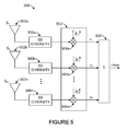
- FIGURE 5 illustrates an example embodiment of the antenna diversity unit 308.
- the antenna diversity unit 308 includes a channel adjust unit 502 having multiple mixers 504a-504n and an accumulator 506.
- the mixers 504a-504n receive the outputs produced by the spread spectrum diversity units 306a-306n and mix those outputs with channel estimates h ⁇ 1 * - h ⁇ N * .
- the channel estimates can be provided by any suitable source(s), such as a controller or other device within a transceiver or wireless node.
- the values produced by the mixers 504a-504n are then summed in the accumulator 506 to produce a final output, which in this case represents the data from wireless signals recovered using spread spectrum diversity combining and antenna diversity combining.
- Each of the components 502-506 includes any suitable structure for performing the described function(s).
- FIGURE 6 illustrates an example receiver 600 that implements a specific type of hybrid diversity combining.
- the receiver 600 includes an analog front-end 602, which includes the antennas 302a-302d, RF front-ends 604a-604d, and analog-to-digital converters (A/D) 604a-604d.
- the RF front-ends 604a-604d can receive and down-convert received RF signals, and the analog-to-digital converters 604a-604d digitize the down-converted signals.
- the digitized signals from the front-end 602 are provided to a spread spectrum unit 608, which includes the spread spectrum diversity units 306a-306n (implemented here using RAKE receivers with MRC, EGC, or SD) that perform spread spectrum diversity combining.
- the outputs of the spread spectrum diversity units 306a-306n are provided to an antenna unit 610, which implements antenna diversity combining using the mixers 504a-504d and the accumulator 506.
- the output of the accumulator 506 is provided to a demodulator 612, which demodulates the received signal.
- a despreader 614 despreads the demodulated signal, such as by multiplying the demodulated signal using a known despreading sequence (such as when DSSS is used).
- spread spectrum diversity using MRC can be combined with antenna diversity using SC.
- multiple signal branches at each antenna (containing electrical signals representing the received wireless signals) are combined with a maximal ratio at that antenna site, and the antenna with the maximum bit SNR can be selected and its output processed to yield the final output.
- spread spectrum diversity using SC can be combined with antenna diversity using MRC.
- the signal branch with the largest SNR at each antenna is selected at the antenna site, and the signal branches from multiple selected antenna sites are combined with a maximal ratio to yield the final output.
- MRC can be used with both spread spectrum diversity and antenna diversity.
- a total of KxN MRC diversity order can be obtained (where K represents the number of signal branches at each antenna site, and N represents the number of antenna sites).
- SC can be used with both spread spectrum diversity and antenna diversity.
- the signal branch with the largest signal can be chosen at each antenna, and the best among the available signals can then be chosen.
- FIGURES 3 through 6 illustrate example receivers using hybrid diversity combining
- various changes may be made to FIGURES 3 through 6 .
- the functional division shown in each of these figures is for illustration only.
- Various components in these figures could be combined, subdivided, or omitted and additional components could be added according to particular needs.
- FIGURE 7 illustrates an example transmitter 700 using adaptive beam forming according to this disclosure.
- the transmitter 700 includes a weight computation unit 702, which receives data to be transmitted and estimates the weights needed to transmit the data.
- the signals to be transmitted can be weighted, such as by using an adaptive signal processing algorithm like a Maximal-Ratio Transmission (MRT) scheme, to form a desired radiation pattern.
- the weights can be computed and adaptively updated in real time.
- MRT Maximal-Ratio Transmission
- phase and gain adjust unit 704 which includes phase adjusters 706a-706n and amplifiers 708a-708n.
- the phase adjusters 706a-706n can be used to adjust the phase of the data being transmitted, and the amplifiers 708a-708n amplify the signals containing the data to be transmitted.
- the amplified signals are provided to multiple antennas 710a-710n for transmission.
- a transmission pattern 712 is created based on the weightings calculated by the weight computation unit 702. Note that the antennas 710a-710n shown in FIGURE 7 could be the same antennas 302a-302n shown in FIGURE 3 .
- the frequency-selective fading channel coefficients can be estimated based on received signals.
- the received signals may be from a single-antenna or multiple-antenna node.
- the channel estimation can be done as part of MRC diversity detection.
- a scheme that enables estimation of the resulting MIMO channel coefficients can be used. Note that, as a MIMO downlink channel is estimated from an uplink channel, the RF front-end of a multiple-antenna node can use the same relative phase shifts across all analog transmit chains that are used across the receive chains.
- a multi-antenna node can form its antenna beam in order to maximize the ratio between radiating power to a desired node and that to other (undesired) nodes.
- the weight computation unit 702 can use any suitable algorithm to compute such a beam-forming weight vector.
- FIGURE 7 illustrates an example transmitter 700 using adaptive beam forming
- various changes may be made to FIGURE 7 .
- the functional division shown in FIGURE 7 is for illustration only.
- Various components in FIGURE 7 could be combined, subdivided, or omitted and additional components could be added according to particular needs.
- the hybrid diversity combining and adaptive beam forming techniques can be used individually or together in an industrial system to improve wireless communications. For example, diversity combining can improve the reliability of down-link communications from leaf nodes to infrastructure nodes. Also, multiple antennas used in receive front-ends can be used to perform transmit beam forming for up-link communications from infrastructure nodes to leaf nodes.
- transmit beam forming can improve the spectral efficiency of the system by forming narrow transmit beams (such as for transmissions to leaf nodes).
- hybrid diversity combining can provide diversity gain at the receiver in flat or selective fading scenarios, which helps to ensure reliable communications in fading channel conditions. Because of diversity gain, a transmitter may require normal transmission power in fading conditions, while lesser transmission power may be needed in conditions without fading.
- transmit beam forming at one radio can help reduce interference with other radios.
- efficient routing can be done using directional beams, and cooperative diversity can help in reducing the number of radios in a specified area.
- a system employing these techniques can have reduced cost and complexity and improved reliability, power efficiency, and spectral efficiency.
- FIGURES 8 and 9 illustrate example methods for improved wireless communications in an industrial control and automation system according to this disclosure.
- a method 800 for adaptive beam forming is described.
- Data to be transmitted wirelessly is received at a transmitter at step 802, and weights to be used to transmit the data are identified at step 804. This could include, for example, identifying weights to be used to direct wireless signals substantially towards a specified destination while reducing or minimizing the wireless signals sent towards other nodes.
- Wireless signals containing the data are then prepared for transmission based on the weights at step 806 and transmitted at step 808. This could include, for example, providing the desired level of amplification and phase shifting to the wireless signals based on the weights.
- Wireless signals are received at multiple antennas at step 902.
- the antennas may be spatially separated from one another by suitable distance(s).
- Spread spectrum diversity combining is performed for each antenna at step 904. This could include, for example, using multiple correlators and an accumulator in a RAKE receiver coupled to each antenna to process the received signals.
- the combining here could have any suitable form, such as maximal ratio combining, equal gain combining, or selection combining.
- Antenna diversity combining is performed using the outputs of the spread spectrum diversity combining at step 906. This could include, for example, using multiple mixers and an accumulator to provide spatial diversity combining.
- the combining here could have any suitable form, such as maximal ratio combining, equal gain combining, or selection combining.
- the output of the antenna diversity combining is further processed at step 908. This could include, for example, demodulating and dispreading the output of the antenna diversity combining, although any other or additional processing steps could also be performed.
- FIGURES 8 and 9 illustrate example methods for improved wireless communications in an industrial control and automation system
- various changes may be made to FIGURES 8 and 9 .
- each figure illustrates a series of steps
- various steps in each figure could overlap, occur in parallel, or occur multiple times.
- various functions described above are implemented or supported by a computer program that is formed from computer readable program code and that is embodied in a computer readable medium.
- computer readable program code includes any type of computer code, including source code, object code, and executable code.
- computer readable medium includes any type of medium capable of being accessed by a computer, such as read only memory (ROM), random access memory (RAM), a hard disk drive, a compact disc (CD), a digital video disc (DVD), or any other type of memory.
- Couple and its derivatives refer to any direct or indirect communication between two or more elements, whether or not those elements are in physical contact with one another.
- transmit and “communicate,” as well as derivatives thereof, encompass both direct and indirect communication.
- the term “or” is inclusive, meaning and/or.
- phrases "associated with” and “associated therewith,” as well as derivatives thereof, may mean to include, be included within, interconnect with, contain, be contained within, connect to or with, couple to or with, be communicable with, cooperate with, interleave, juxtapose, be proximate to, be bound to or with, have, have a property of, have a relationship to or with, or the like.
Landscapes
- Engineering & Computer Science (AREA)
- Computer Networks & Wireless Communication (AREA)
- Signal Processing (AREA)
- Mobile Radio Communication Systems (AREA)
- Radio Transmission System (AREA)
Applications Claiming Priority (1)
| Application Number | Priority Date | Filing Date | Title |
|---|---|---|---|
| US12/471,177 US8374221B2 (en) | 2009-05-22 | 2009-05-22 | Apparatus and method for hybrid diversity combining and adaptive beam forming in industrial control and automation systems |
Publications (3)
| Publication Number | Publication Date |
|---|---|
| EP2254263A2 true EP2254263A2 (de) | 2010-11-24 |
| EP2254263A3 EP2254263A3 (de) | 2013-08-21 |
| EP2254263B1 EP2254263B1 (de) | 2017-06-14 |
Family
ID=42651273
Family Applications (1)
| Application Number | Title | Priority Date | Filing Date |
|---|---|---|---|
| EP10162786.7A Not-in-force EP2254263B1 (de) | 2009-05-22 | 2010-05-13 | Vorrichtung und Verfahren zur hybriden Diversitätskombination und adaptiven Strahlformung in industriellen Steuerungs- und Automatisierungssystemen |
Country Status (2)
| Country | Link |
|---|---|
| US (1) | US8374221B2 (de) |
| EP (1) | EP2254263B1 (de) |
Cited By (2)
| Publication number | Priority date | Publication date | Assignee | Title |
|---|---|---|---|---|
| CN106297250A (zh) * | 2016-10-10 | 2017-01-04 | 普天智能照明研究院有限公司 | 一种远距离家庭数据采集系统和能耗采集系统 |
| WO2020197782A1 (en) * | 2019-03-25 | 2020-10-01 | General Dynamics Mission Systems, Inc. | Cooperative broadcast multi-hop network that employs broadcast flood routing and multi-hop transmission using a direct-sequence spread-spectrum (dsss) waveform with cooperative beamforming and adaptive space-spectrum whitening, and a node for use in a cooperative broadcast multi-hop network having a multi-user rake receiver and/or an adaptive space-spectrum whitener |
Families Citing this family (5)
| Publication number | Priority date | Publication date | Assignee | Title |
|---|---|---|---|---|
| JPWO2011001601A1 (ja) * | 2009-07-03 | 2012-12-10 | パナソニック株式会社 | キャリア周波数同期検出回路及び相関演算器 |
| US9166667B2 (en) | 2011-10-12 | 2015-10-20 | Honeywell International Inc. | Antenna selection diversity scheme for zigbee or other wireless devices and related apparatus and method |
| US9450659B2 (en) * | 2011-11-04 | 2016-09-20 | Alcatel Lucent | Method and apparatus to generate virtual sector wide static beams using phase shift transmit diversity |
| US9065807B2 (en) * | 2012-05-16 | 2015-06-23 | The Boeing Company | Ad-Hoc radio communications system |
| US10290920B2 (en) * | 2016-08-02 | 2019-05-14 | Movandi Corporation | Large scale integration and control of antennas with master chip and front end chips on a single antenna panel |
Family Cites Families (8)
| Publication number | Priority date | Publication date | Assignee | Title |
|---|---|---|---|---|
| JP3274375B2 (ja) * | 1996-11-25 | 2002-04-15 | 松下電器産業株式会社 | スペクトル拡散復調装置 |
| US6882678B2 (en) * | 2000-12-01 | 2005-04-19 | Ning Kong | Method and system for canceling multiple access interference in CDMA wireless communication system |
| JP2004096346A (ja) * | 2002-08-30 | 2004-03-25 | Fujitsu Ltd | 無線通信装置 |
| KR100605861B1 (ko) * | 2004-02-02 | 2006-08-01 | 삼성전자주식회사 | 다중 입력 다중 출력 방식을 사용하는 통신 시스템의 신호수신 장치 및 방법 |
| JP4384667B2 (ja) * | 2004-06-24 | 2009-12-16 | パナソニック株式会社 | 無線送信装置および無線通信方法 |
| JP2008048160A (ja) * | 2006-08-16 | 2008-02-28 | Fujitsu Ltd | 基地局装置及び移動端末の故障検出装置並びにそれらの故障検出方法 |
| US20080077976A1 (en) * | 2006-09-27 | 2008-03-27 | Rockwell Automation Technologies, Inc. | Cryptographic authentication protocol |
| US20080080440A1 (en) * | 2006-09-30 | 2008-04-03 | Yarvis Mark D | Device interfaces to integrate cooperative diversity and mesh networking |
-
2009
- 2009-05-22 US US12/471,177 patent/US8374221B2/en active Active
-
2010
- 2010-05-13 EP EP10162786.7A patent/EP2254263B1/de not_active Not-in-force
Non-Patent Citations (1)
| Title |
|---|
| None |
Cited By (7)
| Publication number | Priority date | Publication date | Assignee | Title |
|---|---|---|---|---|
| CN106297250A (zh) * | 2016-10-10 | 2017-01-04 | 普天智能照明研究院有限公司 | 一种远距离家庭数据采集系统和能耗采集系统 |
| WO2020197782A1 (en) * | 2019-03-25 | 2020-10-01 | General Dynamics Mission Systems, Inc. | Cooperative broadcast multi-hop network that employs broadcast flood routing and multi-hop transmission using a direct-sequence spread-spectrum (dsss) waveform with cooperative beamforming and adaptive space-spectrum whitening, and a node for use in a cooperative broadcast multi-hop network having a multi-user rake receiver and/or an adaptive space-spectrum whitener |
| US11050458B2 (en) | 2019-03-25 | 2021-06-29 | General Dynamics Mission Systems, Inc. | Node having an adaptive space-spectrum whiteniner and multi-user rake receiver for use in a cooperative broadcast multi-hop network that employs broadcast flood routing and multi-hop transmission with cooperative beamforming and adaptive space-spectrum whitening |
| US11082083B2 (en) | 2019-03-25 | 2021-08-03 | General Dynamics Mission Systems, Inc. | Node having a multi-user rake receiver for use in a cooperative broadcast multi-hop network that employs broadcast flood routing and multi-hop transmission with cooperative beamforming |
| US11082084B2 (en) | 2019-03-25 | 2021-08-03 | General Dynamics Mission Systems, Inc. | Receiver for use in a cooperative broadcast multi-hop network |
| US11228338B2 (en) | 2019-03-25 | 2022-01-18 | General Dynamics Mission Systems, Inc. | Method and system of communicating between a plurality of nodes that are part of a cooperative broadcast multi-hop network that employs broadcast flood routing and multi-hop transmission using a direct-sequence spread-spectrum (DSSS) waveform |
| US11552673B2 (en) | 2019-03-25 | 2023-01-10 | General Dynamics Mission Systems, Inc. | Node having an adaptive space-spectrum whitener and multi-user rake receiver for use in a cooperative broadcast multi-hop network that employs broadcast flood routing and multi-hop transmission with cooperative beamforming and adaptive space-spectrum whitening |
Also Published As
| Publication number | Publication date |
|---|---|
| US20100296552A1 (en) | 2010-11-25 |
| US8374221B2 (en) | 2013-02-12 |
| EP2254263A3 (de) | 2013-08-21 |
| EP2254263B1 (de) | 2017-06-14 |
Similar Documents
| Publication | Publication Date | Title |
|---|---|---|
| EP2254263B1 (de) | Vorrichtung und Verfahren zur hybriden Diversitätskombination und adaptiven Strahlformung in industriellen Steuerungs- und Automatisierungssystemen | |
| US6477161B1 (en) | Downlink beamforming approach for frequency division duplex cellular systems | |
| JP3888189B2 (ja) | 適応アンテナ基地局装置 | |
| GB2596437A (en) | Cooperative broadcast multi-hop network that employs broadcast flood routing and multi-hop transmission using a direct-sequence spread-spectrum (DSSS) | |
| KR101488298B1 (ko) | 무선 중계 장치 및 시스템과 그 방법 | |
| JP2007244002A (ja) | スマートアンテナおよびダイバーシティ技法を実施するための方法およびシステム | |
| CA2400990C (en) | Wireless base station apparatus and wireless communication method | |
| EP2208293B1 (de) | Drahtloser empfänger mit empfangs-diversität | |
| NO335958B1 (no) | Fremgangsmåte og anordning for interferenskansellering i et spredtspektrumkommunikasjonssystem | |
| JP2004032656A (ja) | 無線通信装置および到来方向推定方法 | |
| WO2013185150A1 (en) | Method and apparatus for smart adaptive dynamic range multiuser detection radio receiver | |
| US20090227202A1 (en) | Relay | |
| US20080089267A1 (en) | Multi-antenna upgrade for a transceiver | |
| KR100784453B1 (ko) | 이동 통신 시스템의 송수신기 및 이동 통신 시스템의 송수신기의 송수신 방법 | |
| US7340281B2 (en) | Method and system for enhancing reception of wireless communication signals | |
| JP2010193445A (ja) | 2ホップmimoaf中継ネットワークにおいてチャネルを推定する方法 | |
| JP2002290317A (ja) | 送信ダイバーシティ通信装置 | |
| KR20060119895A (ko) | 무선 통신 시스템에서 신호들을 전송하기 위한 방법과 그에상응하는 송신국 및 수신국 | |
| CN105137463B (zh) | 一种基于卫星定位系统的协同分集定位方法 | |
| JP4408262B2 (ja) | 適応アンテナアレー送信装置および適応アンテナアレー送信方法 | |
| JP2006270730A (ja) | 無線通信方法、無線通信システム及び無線通信装置 | |
| WO2010059780A2 (en) | Code division multiple access based contingency transmission | |
| JP5729837B2 (ja) | 基地局装置、無線通信方法、及び無線通信システム | |
| JP4139233B2 (ja) | 無線受信機 | |
| Kunze et al. | Receive antenna diversity architectures for HSDPA |
Legal Events
| Date | Code | Title | Description |
|---|---|---|---|
| PUAI | Public reference made under article 153(3) epc to a published international application that has entered the european phase |
Free format text: ORIGINAL CODE: 0009012 |
|
| 17P | Request for examination filed |
Effective date: 20100513 |
|
| AK | Designated contracting states |
Kind code of ref document: A2 Designated state(s): AL AT BE BG CH CY CZ DE DK EE ES FI FR GB GR HR HU IE IS IT LI LT LU LV MC MK MT NL NO PL PT RO SE SI SK SM TR |
|
| AX | Request for extension of the european patent |
Extension state: BA ME RS |
|
| PUAL | Search report despatched |
Free format text: ORIGINAL CODE: 0009013 |
|
| AK | Designated contracting states |
Kind code of ref document: A3 Designated state(s): AL AT BE BG CH CY CZ DE DK EE ES FI FR GB GR HR HU IE IS IT LI LT LU LV MC MK MT NL NO PL PT RO SE SI SK SM TR |
|
| AX | Request for extension of the european patent |
Extension state: BA ME RS |
|
| RIC1 | Information provided on ipc code assigned before grant |
Ipc: H04B 1/707 20110101ALI20130715BHEP Ipc: H04B 7/06 20060101ALI20130715BHEP Ipc: H04B 7/08 20060101AFI20130715BHEP Ipc: H04B 7/04 20060101ALI20130715BHEP |
|
| 17Q | First examination report despatched |
Effective date: 20130802 |
|
| RAP1 | Party data changed (applicant data changed or rights of an application transferred) |
Owner name: HONEYWELL INTERNATIONAL INC. |
|
| GRAP | Despatch of communication of intention to grant a patent |
Free format text: ORIGINAL CODE: EPIDOSNIGR1 |
|
| INTG | Intention to grant announced |
Effective date: 20170104 |
|
| RIN1 | Information on inventor provided before grant (corrected) |
Inventor name: BUDAMPATI, RAMAKRISHNA S. Inventor name: KATURI, SRINIVASARAO Inventor name: MAHASENAN, ARUN V. |
|
| GRAS | Grant fee paid |
Free format text: ORIGINAL CODE: EPIDOSNIGR3 |
|
| GRAA | (expected) grant |
Free format text: ORIGINAL CODE: 0009210 |
|
| AK | Designated contracting states |
Kind code of ref document: B1 Designated state(s): AL AT BE BG CH CY CZ DE DK EE ES FI FR GB GR HR HU IE IS IT LI LT LU LV MC MK MT NL NO PL PT RO SE SI SK SM TR |
|
| REG | Reference to a national code |
Ref country code: GB Ref legal event code: FG4D |
|
| REG | Reference to a national code |
Ref country code: CH Ref legal event code: EP Ref country code: AT Ref legal event code: REF Ref document number: 901865 Country of ref document: AT Kind code of ref document: T Effective date: 20170615 |
|
| REG | Reference to a national code |
Ref country code: IE Ref legal event code: FG4D |
|
| REG | Reference to a national code |
Ref country code: DE Ref legal event code: R096 Ref document number: 602010042915 Country of ref document: DE |
|
| REG | Reference to a national code |
Ref country code: NL Ref legal event code: MP Effective date: 20170614 |
|
| REG | Reference to a national code |
Ref country code: LT Ref legal event code: MG4D |
|
| PG25 | Lapsed in a contracting state [announced via postgrant information from national office to epo] |
Ref country code: ES Free format text: LAPSE BECAUSE OF FAILURE TO SUBMIT A TRANSLATION OF THE DESCRIPTION OR TO PAY THE FEE WITHIN THE PRESCRIBED TIME-LIMIT Effective date: 20170614 Ref country code: HR Free format text: LAPSE BECAUSE OF FAILURE TO SUBMIT A TRANSLATION OF THE DESCRIPTION OR TO PAY THE FEE WITHIN THE PRESCRIBED TIME-LIMIT Effective date: 20170614 Ref country code: GR Free format text: LAPSE BECAUSE OF FAILURE TO SUBMIT A TRANSLATION OF THE DESCRIPTION OR TO PAY THE FEE WITHIN THE PRESCRIBED TIME-LIMIT Effective date: 20170915 Ref country code: NO Free format text: LAPSE BECAUSE OF FAILURE TO SUBMIT A TRANSLATION OF THE DESCRIPTION OR TO PAY THE FEE WITHIN THE PRESCRIBED TIME-LIMIT Effective date: 20170914 Ref country code: LT Free format text: LAPSE BECAUSE OF FAILURE TO SUBMIT A TRANSLATION OF THE DESCRIPTION OR TO PAY THE FEE WITHIN THE PRESCRIBED TIME-LIMIT Effective date: 20170614 Ref country code: FI Free format text: LAPSE BECAUSE OF FAILURE TO SUBMIT A TRANSLATION OF THE DESCRIPTION OR TO PAY THE FEE WITHIN THE PRESCRIBED TIME-LIMIT Effective date: 20170614 |
|
| REG | Reference to a national code |
Ref country code: AT Ref legal event code: MK05 Ref document number: 901865 Country of ref document: AT Kind code of ref document: T Effective date: 20170614 |
|
| PG25 | Lapsed in a contracting state [announced via postgrant information from national office to epo] |
Ref country code: SE Free format text: LAPSE BECAUSE OF FAILURE TO SUBMIT A TRANSLATION OF THE DESCRIPTION OR TO PAY THE FEE WITHIN THE PRESCRIBED TIME-LIMIT Effective date: 20170614 Ref country code: BG Free format text: LAPSE BECAUSE OF FAILURE TO SUBMIT A TRANSLATION OF THE DESCRIPTION OR TO PAY THE FEE WITHIN THE PRESCRIBED TIME-LIMIT Effective date: 20170914 Ref country code: LV Free format text: LAPSE BECAUSE OF FAILURE TO SUBMIT A TRANSLATION OF THE DESCRIPTION OR TO PAY THE FEE WITHIN THE PRESCRIBED TIME-LIMIT Effective date: 20170614 Ref country code: NL Free format text: LAPSE BECAUSE OF FAILURE TO SUBMIT A TRANSLATION OF THE DESCRIPTION OR TO PAY THE FEE WITHIN THE PRESCRIBED TIME-LIMIT Effective date: 20170614 |
|
| PG25 | Lapsed in a contracting state [announced via postgrant information from national office to epo] |
Ref country code: RO Free format text: LAPSE BECAUSE OF FAILURE TO SUBMIT A TRANSLATION OF THE DESCRIPTION OR TO PAY THE FEE WITHIN THE PRESCRIBED TIME-LIMIT Effective date: 20170614 Ref country code: CZ Free format text: LAPSE BECAUSE OF FAILURE TO SUBMIT A TRANSLATION OF THE DESCRIPTION OR TO PAY THE FEE WITHIN THE PRESCRIBED TIME-LIMIT Effective date: 20170614 Ref country code: SK Free format text: LAPSE BECAUSE OF FAILURE TO SUBMIT A TRANSLATION OF THE DESCRIPTION OR TO PAY THE FEE WITHIN THE PRESCRIBED TIME-LIMIT Effective date: 20170614 Ref country code: AT Free format text: LAPSE BECAUSE OF FAILURE TO SUBMIT A TRANSLATION OF THE DESCRIPTION OR TO PAY THE FEE WITHIN THE PRESCRIBED TIME-LIMIT Effective date: 20170614 Ref country code: EE Free format text: LAPSE BECAUSE OF FAILURE TO SUBMIT A TRANSLATION OF THE DESCRIPTION OR TO PAY THE FEE WITHIN THE PRESCRIBED TIME-LIMIT Effective date: 20170614 |
|
| PG25 | Lapsed in a contracting state [announced via postgrant information from national office to epo] |
Ref country code: IT Free format text: LAPSE BECAUSE OF FAILURE TO SUBMIT A TRANSLATION OF THE DESCRIPTION OR TO PAY THE FEE WITHIN THE PRESCRIBED TIME-LIMIT Effective date: 20170614 Ref country code: IS Free format text: LAPSE BECAUSE OF FAILURE TO SUBMIT A TRANSLATION OF THE DESCRIPTION OR TO PAY THE FEE WITHIN THE PRESCRIBED TIME-LIMIT Effective date: 20171014 Ref country code: SM Free format text: LAPSE BECAUSE OF FAILURE TO SUBMIT A TRANSLATION OF THE DESCRIPTION OR TO PAY THE FEE WITHIN THE PRESCRIBED TIME-LIMIT Effective date: 20170614 Ref country code: PL Free format text: LAPSE BECAUSE OF FAILURE TO SUBMIT A TRANSLATION OF THE DESCRIPTION OR TO PAY THE FEE WITHIN THE PRESCRIBED TIME-LIMIT Effective date: 20170614 |
|
| REG | Reference to a national code |
Ref country code: DE Ref legal event code: R097 Ref document number: 602010042915 Country of ref document: DE |
|
| PLBE | No opposition filed within time limit |
Free format text: ORIGINAL CODE: 0009261 |
|
| STAA | Information on the status of an ep patent application or granted ep patent |
Free format text: STATUS: NO OPPOSITION FILED WITHIN TIME LIMIT |
|
| PG25 | Lapsed in a contracting state [announced via postgrant information from national office to epo] |
Ref country code: DK Free format text: LAPSE BECAUSE OF FAILURE TO SUBMIT A TRANSLATION OF THE DESCRIPTION OR TO PAY THE FEE WITHIN THE PRESCRIBED TIME-LIMIT Effective date: 20170614 |
|
| 26N | No opposition filed |
Effective date: 20180315 |
|
| REG | Reference to a national code |
Ref country code: FR Ref legal event code: PLFP Year of fee payment: 9 |
|
| PG25 | Lapsed in a contracting state [announced via postgrant information from national office to epo] |
Ref country code: SI Free format text: LAPSE BECAUSE OF FAILURE TO SUBMIT A TRANSLATION OF THE DESCRIPTION OR TO PAY THE FEE WITHIN THE PRESCRIBED TIME-LIMIT Effective date: 20170614 |
|
| PGFP | Annual fee paid to national office [announced via postgrant information from national office to epo] |
Ref country code: FR Payment date: 20180525 Year of fee payment: 9 |
|
| PGFP | Annual fee paid to national office [announced via postgrant information from national office to epo] |
Ref country code: DE Payment date: 20180731 Year of fee payment: 9 Ref country code: GB Payment date: 20180530 Year of fee payment: 9 |
|
| REG | Reference to a national code |
Ref country code: CH Ref legal event code: PL |
|
| REG | Reference to a national code |
Ref country code: BE Ref legal event code: MM Effective date: 20180531 |
|
| PG25 | Lapsed in a contracting state [announced via postgrant information from national office to epo] |
Ref country code: MC Free format text: LAPSE BECAUSE OF FAILURE TO SUBMIT A TRANSLATION OF THE DESCRIPTION OR TO PAY THE FEE WITHIN THE PRESCRIBED TIME-LIMIT Effective date: 20170614 |
|
| REG | Reference to a national code |
Ref country code: IE Ref legal event code: MM4A |
|
| PG25 | Lapsed in a contracting state [announced via postgrant information from national office to epo] |
Ref country code: CH Free format text: LAPSE BECAUSE OF NON-PAYMENT OF DUE FEES Effective date: 20180531 Ref country code: LI Free format text: LAPSE BECAUSE OF NON-PAYMENT OF DUE FEES Effective date: 20180531 |
|
| PG25 | Lapsed in a contracting state [announced via postgrant information from national office to epo] |
Ref country code: LU Free format text: LAPSE BECAUSE OF NON-PAYMENT OF DUE FEES Effective date: 20180513 |
|
| PG25 | Lapsed in a contracting state [announced via postgrant information from national office to epo] |
Ref country code: IE Free format text: LAPSE BECAUSE OF NON-PAYMENT OF DUE FEES Effective date: 20180513 |
|
| PG25 | Lapsed in a contracting state [announced via postgrant information from national office to epo] |
Ref country code: BE Free format text: LAPSE BECAUSE OF NON-PAYMENT OF DUE FEES Effective date: 20180531 |
|
| REG | Reference to a national code |
Ref country code: DE Ref legal event code: R119 Ref document number: 602010042915 Country of ref document: DE |
|
| GBPC | Gb: european patent ceased through non-payment of renewal fee |
Effective date: 20190513 |
|
| PG25 | Lapsed in a contracting state [announced via postgrant information from national office to epo] |
Ref country code: MT Free format text: LAPSE BECAUSE OF NON-PAYMENT OF DUE FEES Effective date: 20180513 |
|
| PG25 | Lapsed in a contracting state [announced via postgrant information from national office to epo] |
Ref country code: TR Free format text: LAPSE BECAUSE OF FAILURE TO SUBMIT A TRANSLATION OF THE DESCRIPTION OR TO PAY THE FEE WITHIN THE PRESCRIBED TIME-LIMIT Effective date: 20170614 |
|
| PG25 | Lapsed in a contracting state [announced via postgrant information from national office to epo] |
Ref country code: GB Free format text: LAPSE BECAUSE OF NON-PAYMENT OF DUE FEES Effective date: 20190513 Ref country code: DE Free format text: LAPSE BECAUSE OF NON-PAYMENT OF DUE FEES Effective date: 20191203 |
|
| PG25 | Lapsed in a contracting state [announced via postgrant information from national office to epo] |
Ref country code: PT Free format text: LAPSE BECAUSE OF FAILURE TO SUBMIT A TRANSLATION OF THE DESCRIPTION OR TO PAY THE FEE WITHIN THE PRESCRIBED TIME-LIMIT Effective date: 20170614 Ref country code: HU Free format text: LAPSE BECAUSE OF FAILURE TO SUBMIT A TRANSLATION OF THE DESCRIPTION OR TO PAY THE FEE WITHIN THE PRESCRIBED TIME-LIMIT; INVALID AB INITIO Effective date: 20100513 |
|
| PG25 | Lapsed in a contracting state [announced via postgrant information from national office to epo] |
Ref country code: CY Free format text: LAPSE BECAUSE OF FAILURE TO SUBMIT A TRANSLATION OF THE DESCRIPTION OR TO PAY THE FEE WITHIN THE PRESCRIBED TIME-LIMIT Effective date: 20170614 Ref country code: FR Free format text: LAPSE BECAUSE OF NON-PAYMENT OF DUE FEES Effective date: 20190531 Ref country code: MK Free format text: LAPSE BECAUSE OF NON-PAYMENT OF DUE FEES Effective date: 20170614 |
|
| PG25 | Lapsed in a contracting state [announced via postgrant information from national office to epo] |
Ref country code: AL Free format text: LAPSE BECAUSE OF FAILURE TO SUBMIT A TRANSLATION OF THE DESCRIPTION OR TO PAY THE FEE WITHIN THE PRESCRIBED TIME-LIMIT Effective date: 20170614 |