EP2254198B1 - Process for improving the reflectivity of antenna reflecting surfaces - Google Patents
Process for improving the reflectivity of antenna reflecting surfaces Download PDFInfo
- Publication number
- EP2254198B1 EP2254198B1 EP09382071.0A EP09382071A EP2254198B1 EP 2254198 B1 EP2254198 B1 EP 2254198B1 EP 09382071 A EP09382071 A EP 09382071A EP 2254198 B1 EP2254198 B1 EP 2254198B1
- Authority
- EP
- European Patent Office
- Prior art keywords
- layer
- composite
- reflectivity
- plastic
- improving
- Prior art date
- Legal status (The legal status is an assumption and is not a legal conclusion. Google has not performed a legal analysis and makes no representation as to the accuracy of the status listed.)
- Active
Links
Images


Classifications
-
- H—ELECTRICITY
- H01—ELECTRIC ELEMENTS
- H01Q—ANTENNAS, i.e. RADIO AERIALS
- H01Q15/00—Devices for reflection, refraction, diffraction or polarisation of waves radiated from an antenna, e.g. quasi-optical devices
- H01Q15/14—Reflecting surfaces; Equivalent structures
- H01Q15/141—Apparatus or processes specially adapted for manufacturing reflecting surfaces
-
- B—PERFORMING OPERATIONS; TRANSPORTING
- B29—WORKING OF PLASTICS; WORKING OF SUBSTANCES IN A PLASTIC STATE IN GENERAL
- B29C—SHAPING OR JOINING OF PLASTICS; SHAPING OF MATERIAL IN A PLASTIC STATE, NOT OTHERWISE PROVIDED FOR; AFTER-TREATMENT OF THE SHAPED PRODUCTS, e.g. REPAIRING
- B29C70/00—Shaping composites, i.e. plastics material comprising reinforcements, fillers or preformed parts, e.g. inserts
- B29C70/04—Shaping composites, i.e. plastics material comprising reinforcements, fillers or preformed parts, e.g. inserts comprising reinforcements only, e.g. self-reinforcing plastics
- B29C70/06—Fibrous reinforcements only
- B29C70/08—Fibrous reinforcements only comprising combinations of different forms of fibrous reinforcements incorporated in matrix material, forming one or more layers, and with or without non-reinforced layers
- B29C70/088—Fibrous reinforcements only comprising combinations of different forms of fibrous reinforcements incorporated in matrix material, forming one or more layers, and with or without non-reinforced layers and with one or more layers of non-plastics material or non-specified material, e.g. supports
-
- B—PERFORMING OPERATIONS; TRANSPORTING
- B29—WORKING OF PLASTICS; WORKING OF SUBSTANCES IN A PLASTIC STATE IN GENERAL
- B29C—SHAPING OR JOINING OF PLASTICS; SHAPING OF MATERIAL IN A PLASTIC STATE, NOT OTHERWISE PROVIDED FOR; AFTER-TREATMENT OF THE SHAPED PRODUCTS, e.g. REPAIRING
- B29C70/00—Shaping composites, i.e. plastics material comprising reinforcements, fillers or preformed parts, e.g. inserts
- B29C70/04—Shaping composites, i.e. plastics material comprising reinforcements, fillers or preformed parts, e.g. inserts comprising reinforcements only, e.g. self-reinforcing plastics
- B29C70/28—Shaping operations therefor
- B29C70/40—Shaping or impregnating by compression not applied
- B29C70/42—Shaping or impregnating by compression not applied for producing articles of definite length, i.e. discrete articles
- B29C70/44—Shaping or impregnating by compression not applied for producing articles of definite length, i.e. discrete articles using isostatic pressure, e.g. pressure difference-moulding, vacuum bag-moulding, autoclave-moulding or expanding rubber-moulding
-
- B—PERFORMING OPERATIONS; TRANSPORTING
- B29—WORKING OF PLASTICS; WORKING OF SUBSTANCES IN A PLASTIC STATE IN GENERAL
- B29C—SHAPING OR JOINING OF PLASTICS; SHAPING OF MATERIAL IN A PLASTIC STATE, NOT OTHERWISE PROVIDED FOR; AFTER-TREATMENT OF THE SHAPED PRODUCTS, e.g. REPAIRING
- B29C70/00—Shaping composites, i.e. plastics material comprising reinforcements, fillers or preformed parts, e.g. inserts
- B29C70/88—Shaping composites, i.e. plastics material comprising reinforcements, fillers or preformed parts, e.g. inserts characterised primarily by possessing specific properties, e.g. electrically conductive or locally reinforced
-
- B—PERFORMING OPERATIONS; TRANSPORTING
- B32—LAYERED PRODUCTS
- B32B—LAYERED PRODUCTS, i.e. PRODUCTS BUILT-UP OF STRATA OF FLAT OR NON-FLAT, e.g. CELLULAR OR HONEYCOMB, FORM
- B32B38/00—Ancillary operations in connection with laminating processes
- B32B2038/0052—Other operations not otherwise provided for
- B32B2038/0076—Curing, vulcanising, cross-linking
-
- B—PERFORMING OPERATIONS; TRANSPORTING
- B32—LAYERED PRODUCTS
- B32B—LAYERED PRODUCTS, i.e. PRODUCTS BUILT-UP OF STRATA OF FLAT OR NON-FLAT, e.g. CELLULAR OR HONEYCOMB, FORM
- B32B38/00—Ancillary operations in connection with laminating processes
- B32B2038/0052—Other operations not otherwise provided for
- B32B2038/0092—Metallizing
-
- B—PERFORMING OPERATIONS; TRANSPORTING
- B32—LAYERED PRODUCTS
- B32B—LAYERED PRODUCTS, i.e. PRODUCTS BUILT-UP OF STRATA OF FLAT OR NON-FLAT, e.g. CELLULAR OR HONEYCOMB, FORM
- B32B2305/00—Condition, form or state of the layers or laminate
- B32B2305/07—Parts immersed or impregnated in a matrix
- B32B2305/076—Prepregs
-
- B—PERFORMING OPERATIONS; TRANSPORTING
- B32—LAYERED PRODUCTS
- B32B—LAYERED PRODUCTS, i.e. PRODUCTS BUILT-UP OF STRATA OF FLAT OR NON-FLAT, e.g. CELLULAR OR HONEYCOMB, FORM
- B32B2307/00—Properties of the layers or laminate
- B32B2307/20—Properties of the layers or laminate having particular electrical or magnetic properties, e.g. piezoelectric
-
- B—PERFORMING OPERATIONS; TRANSPORTING
- B32—LAYERED PRODUCTS
- B32B—LAYERED PRODUCTS, i.e. PRODUCTS BUILT-UP OF STRATA OF FLAT OR NON-FLAT, e.g. CELLULAR OR HONEYCOMB, FORM
- B32B38/00—Ancillary operations in connection with laminating processes
- B32B38/10—Removing layers, or parts of layers, mechanically or chemically
-
- Y—GENERAL TAGGING OF NEW TECHNOLOGICAL DEVELOPMENTS; GENERAL TAGGING OF CROSS-SECTIONAL TECHNOLOGIES SPANNING OVER SEVERAL SECTIONS OF THE IPC; TECHNICAL SUBJECTS COVERED BY FORMER USPC CROSS-REFERENCE ART COLLECTIONS [XRACs] AND DIGESTS
- Y10—TECHNICAL SUBJECTS COVERED BY FORMER USPC
- Y10T—TECHNICAL SUBJECTS COVERED BY FORMER US CLASSIFICATION
- Y10T156/00—Adhesive bonding and miscellaneous chemical manufacture
- Y10T156/10—Methods of surface bonding and/or assembly therefor
- Y10T156/1052—Methods of surface bonding and/or assembly therefor with cutting, punching, tearing or severing
- Y10T156/1062—Prior to assembly
Definitions
- the present invention relates to a process for improving the reflectivity of reflective surfaces of antennas, said reflective surfaces being made of a composite.
- An antenna is a device designed for the purpose of emitting or receiving electromagnetic waves towards open space. While a transmitter antenna transforms voltages into electromagnetic waves, a receiver antenna performs the reverse function.
- the traditional classification of antennas is essentially based on the manner in which the electromagnetic field is distributed in the antenna itself or on the technology used, although classifications can also be made from a more practical point of view, based on their features and technology, their specific uses and their operation.
- the manner of producing and receiving electromagnetic waves is done through one or more reflective surfaces, also known as reflectors. If a large main reflector and/or large focal distance involving large distances to the focus needs to be used, then one or more secondary reflectors or subreflectors are normally used, apart from the main reflector. Whereas the main reflector reflects the incident radiation towards the primary focus, the secondary reflector or subreflector has one focus in common with the parabolic reflector and forwards the electromagnetic waves to the secondary focus.
- the present invention relates to reflective elements (main reflector and/or subreflectors) of the antennas on board telecommunications, radar, radiometer, radio telescope and Earth observation satellites, as well as for other applications.
- the reflective elements are made of a composite, the loss of reflectivity (reflectivity being the ability of reflective surfaces to reflect the incident radiation thereon) increases as the frequency increases. Therefore, depending on the work frequency of the mentioned antennas, the reflectivity of their reflective surfaces must be high enough so as to not cause losses which unacceptably degrade the features of said antennas.
- composites formed by a fiber (carbon, glass, quartz, etc.) and a resin matrix are used. These materials have either an intrinsically low reflectivity (quartz, glass) or a reflectivity which deteriorates to unacceptable values for high frequencies (from 15 GHz or 20 GHz) due to the ohmic losses occurring when carbon fiber is used as a composite, both if this carbon fiber is painted or unpainted, it being necessary to consider solutions improving the reflectivity of these surfaces.
- One of the processes used today for improving the reflectivity of antenna reflectors made of a composite consists of arranging a metallized layer (process referred to as metallization) on said reflectors.
- the reduction in the loss of reflectivity is a function of the temperature, of the purity of the metallized layer and of the thickness thereof.
- the physical methods can in turn be sub-divided into two groups: metal spraying processes and vacuum deposition processes.
- the metal spraying can in turn be performed by several techniques (flame spraying, electro spraying and plasma spraying). They all essentially consist of raising the temperature of the metal to be deposited above the melting temperature thereof, subsequently projecting the resulting particles by means of special guns.
- Vacuum deposition can also use several techniques (vaporization, sputtering and ion plating), atoms of metal or vaporized metal being deposited in all of them on the substrate to be metallized in a vacuum environment.
- the chemical methods in turn include several processes, such as auto-catalytic coating, electrodeposition and chemical vapor deposition.
- Auto-catalytic coating consists of activating the surfaces to be metallized such that metal ions generated in a solution prepared for such purpose are deposited thereon.
- Electrodeposition consists of depositing a metal on a surface upon passing a current in a bath in which the surface to be metallized is introduced.
- the vacuum deposition metallization technique commonly used in which the material with elevated conductivity is mainly aluminum, produces very thin and very sensitive metallization depositions arranged on the outer face of the surfaces, these metallization layers being very easily damaged, even when cleaning the surfaces, the metallization layer in many cases being removed when the process of cleaning said surfaces is performed. In the event that the metallization layer is damaged, it is necessary to remove the entire arranged layer and again perform the metallization process once more, which involves a very high cost.
- the present invention is aimed at solving the previously mentioned drawbacks.
- the invention describes a process for improving the reflectivity of reflective surfaces of antennas as defined in the sole independent claim 1, said reflective surfaces being made of a composite, upon imbedding a layer of metallized dielectric plastic between the layers of composite or in the outer surface of the reflective surface of the antenna which must have given reflective characteristics in the antenna.
- This layer of metallized dielectric plastic is arranged while laminating the composite that is going to form the mentioned reflective surface.
- the layer of metallized plastic which is imbedded in the reflector can be arranged in strips with a suitable size in order to achieve optimal adaptation to the reflective surface to be metallized, or forming different shapes following determined patterns.
- the reflective surface can then be metallized continuously, i.e., the previous strips being adapted such that they completely cover the entire reflective surface or arranging the previous strips discontinuously, such that they do not completely cover the previous reflective surface, but rather they are only arranged in some determined areas thereof.
- the metallization of the metallized strips forming determined patterns or shapes can also be removed to achieve special effects. When the metallization is discontinuous (either by means of metallized strips or by means of patterns) it can in turn be periodic or non-periodic.
- These periodic or non-periodic metallization shapes can achieve several effects improving the characteristics of the antennas, such as polarizing the electromagnetic fields, altering their phase and amplitude and, in summary, controlling the radiation diagram of the antenna in a simple manner.
- the metallized layer is bonded to the composite substrate of the reflective surface by the resin itself of the composite, as this metallized layer is imbedded during the process of laminating the composite of the reflective surface itself, thus entering the curing cycle as part of the assembly of the reflective surface (formed by the composite together with the metallized plastic).
- the process of the invention for performing the metallization of reflective surfaces of antennas, particularly for satellites, said reflective surfaces being made of composite, by means of which the reflectivity of said reflective surfaces is improved, upon reducing the losses of reflectivity thereof, comprises the following steps:
- the invention describes a process for improving the reflectivity of reflective surfaces 1 of antennas arranged in satellites, said reflective surfaces 1 being made of a composite.
- the composite comprises a resin matrix and fibers, these fibers preferably being carbon fibers.
- a layer of metallized dielectric plastic 3 is imbedded by means of a metallization layer 4 between the layers of composite 2 ( Figure 1 ) or in the outer surface of the reflector of the antenna which must have given reflective characteristics ( Figure 2 ).
- the layer of metallized dielectric plastic 3 (metallized by means of the metallization layer 4) is arranged while laminating the composite which will form the mentioned reflector or reflective surface 1.
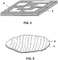
- the layer of plastic 3 comprising the previous metallization layer 4 is imbedded in the reflective surface 1 and can be arranged in strips with a suitable size in order to achieve optimal adaptation to the reflective surface 1 to be metallized, or forming different shapes following determined patterns ( Figures 3, 4 and 5 ).
- the reflective surface 1 can be metallized continuously ( Figures 4 and 5 ), or discontinuously ( Figure 3 ).
- the metallization of the metallized strips forming determined patterns or shapes can be also be removed in order to achieve special effects. When the metallization is discontinuous, it can in turn be periodic or non-periodic.
- the metallized layer 4 is bonded to the composite substrate 2 of the reflective surface 1 by the resin itself of the composite of layer 2, as this metallized layer 4 is imbedded during the process of laminating the composite 2 of the reflective surface 1 itself, thus entering the curing cycle as part of the assembly of the reflective surface 1 (formed by the composite 2 together with the plastic 3 comprising a metallization layer 4).
- the process of the invention comprises the following steps (according to the application, some steps may not be necessary):
- Figure 1 shows how the layers of the different materials are arranged to form the reflective surface 1 with the process of the invention. According to the application, some of these layers may be partially or completely eliminated.
- Figure 2 in turn shows a layer of support plastic 3 on which the previously deposited continuous metallization layer 4 is seen.
- Figure 3 depicts a layer of plastic 3 on which the previously deposited metallization layer 4 can be seen after having partially removed said metallization layer 4 in order to achieve modifying the response of the electromagnetic waves.
- the part which remains metallized (layer 4) can be periodic or not and the patterns can be identical or different in each area.
- This metallized layer 4 could also be a negative image.
- Figure 4 shows a reflective surface 1 comprising metallized layers 4 arranged in the form of strips.
- Figures 5 shows a reflective surface 1 with another type of strips (the strips can have any shape and size), according to another embodiment of the invention.
- Figures 3, 4 and 5 show different embodiments of the arrangement of the metallization layer 4.
- the metallization layer 4 can be arranged between the layers of composite 2 (as shown in Figure 1 ), or in the outer surface of the reflective surface 1 of the antenna, which must have given reflective characteristics (as shown in Figure 2 ).
- the plastic 3 comprising a metallization layer 4 is bonded to the composite 2 in step a) in its preimpregnated state.
- the sheets of the composite 2 and metallized plastic (layers 3+4) assembly are cut in step b) in a suitable manner in order to perform the lamination of step d).
- the resin of the composite of layer 2 is polymerized, and with it, the metallized plastic (layers 3+4) and the composite substrate of layer 2 bond together.
- step d) for the purpose of protecting the metal of the metallization layer 4, the metallized plastic (layers 3+4) is placed with the plastic face (layer 3) arranged outwardly, such that the metallization layer 4 is protected since it is covered by the plastic of layer 3 and is therefore not exposed to the external environment or to possible contamination by contact or by lack of cleaning.
- the adhesion of the metallization layer or metallized layer 4 to the substrate of the composite of layer 2 is better than in the case of glued metallic layers (by means of the vacuum deposition or chemical deposition process), given that, during the entire polymerization process of the resin of the composite in step h), a pressure is maintained (that of the curing cycle) assuring suitable contact between the surfaces to be bonded, the previous adhesion being much better than the adhesion of metal deposition by vacuum or by chemical process, because in the last cases, the adhesion is very dependent on the suitable activation of the surfaces, as well as on the cleaning of the substrate of the composite of layer 2.
- the process of the invention furthermore does not require complex metallization installations as in the known technique, but rather it can be performed in the same installations in which the elements of the composite are manufactured without having to change anything in the installation.
- the process of the invention can be performed using any type of metallized plastic, which involves any type of plastic existing on the market (preferably Kapton, Kapton loaded with any type of material, Polyamide, Polyamide loaded with any type of material) or any type of metal (preferably aluminum, silver or gold).
- the thickness of the metallization layer 4 can be any thickness, ranging from the finest thickness (in the order of 8 microns), to the thickest thickness (in the order of 50 microns or 100 microns).
- the substrate of the composite of layer 2 on which the process of the invention is performed can be of any type of composite in which the resin of said composite is polymerized in the curing process.
- the metallization (metallization layers 4) of the reflective surfaces 1 can be performed continuously (using metallization strips), Figures 4 and 5 , or discontinuously (by means of metallization strips or by means of patterns), Figure 3 .
- the metallization may in turn be periodic or non-periodic.
- Being able to change this metallization in a periodic or non-periodic manner has the advantage of being able to change the electromagnetic characteristics of the reflective surface 1 of the antenna, filtering polarization, filtering frequencies or converting one polarization into another.
- the electromagnetic behavior of said wave in turn changes, thus being able to control said behavior according to the required needs.
Landscapes
- Engineering & Computer Science (AREA)
- Chemical & Material Sciences (AREA)
- Composite Materials (AREA)
- Mechanical Engineering (AREA)
- Manufacturing & Machinery (AREA)
- Physics & Mathematics (AREA)
- Electromagnetism (AREA)
- Aerials With Secondary Devices (AREA)
- Casting Or Compression Moulding Of Plastics Or The Like (AREA)
- Laminated Bodies (AREA)
Priority Applications (5)
| Application Number | Priority Date | Filing Date | Title |
|---|---|---|---|
| ES09382071.0T ES2652121T3 (es) | 2009-05-18 | 2009-05-18 | Procedimiento para mejorar la reflectividad de superficies reflectoras de antenas |
| EP09382071.0A EP2254198B1 (en) | 2009-05-18 | 2009-05-18 | Process for improving the reflectivity of antenna reflecting surfaces |
| CA2704531A CA2704531C (en) | 2009-05-18 | 2010-05-17 | Process for improving the reflectivity of reflective surfaces of antennas |
| JP2010113626A JP5722552B2 (ja) | 2009-05-18 | 2010-05-17 | アンテナの反射面の反射率を高めるプロセス |
| US12/782,491 US8317960B2 (en) | 2009-05-18 | 2010-05-18 | Process for improving the reflectivity of reflective surfaces of antennas |
Applications Claiming Priority (1)
| Application Number | Priority Date | Filing Date | Title |
|---|---|---|---|
| EP09382071.0A EP2254198B1 (en) | 2009-05-18 | 2009-05-18 | Process for improving the reflectivity of antenna reflecting surfaces |
Publications (2)
| Publication Number | Publication Date |
|---|---|
| EP2254198A1 EP2254198A1 (en) | 2010-11-24 |
| EP2254198B1 true EP2254198B1 (en) | 2017-09-27 |
Family
ID=41137197
Family Applications (1)
| Application Number | Title | Priority Date | Filing Date |
|---|---|---|---|
| EP09382071.0A Active EP2254198B1 (en) | 2009-05-18 | 2009-05-18 | Process for improving the reflectivity of antenna reflecting surfaces |
Country Status (5)
| Country | Link |
|---|---|
| US (1) | US8317960B2 (es) |
| EP (1) | EP2254198B1 (es) |
| JP (1) | JP5722552B2 (es) |
| CA (1) | CA2704531C (es) |
| ES (1) | ES2652121T3 (es) |
Families Citing this family (13)
| Publication number | Priority date | Publication date | Assignee | Title |
|---|---|---|---|---|
| CN102157786A (zh) * | 2010-12-10 | 2011-08-17 | 中国兵器工业第二○六研究所 | 复合材料带状线天线加工方法 |
| ITRM20120020A1 (it) | 2012-01-20 | 2013-07-21 | Unilab S A S Di Lavagna Silvio Mas Simo & C | Processo per migliorare la riflettivita' delle superfici riflettenti di antenne. |
| ITRM20130397A1 (it) | 2013-07-08 | 2015-01-09 | Silvio Massimo Lavagna | Processo per riflettori metallizzati per alte frequenze. |
| US9789664B2 (en) | 2013-07-09 | 2017-10-17 | United Technologies Corporation | Plated tubular lattice structure |
| CA2917916A1 (en) | 2013-07-09 | 2015-02-05 | United Technologies Corporation | Plated polymer nosecone |
| WO2015006452A1 (en) * | 2013-07-09 | 2015-01-15 | United Technologies Corporation | Vehicular engine and transmission components made of plated polymers |
| US11268526B2 (en) | 2013-07-09 | 2022-03-08 | Raytheon Technologies Corporation | Plated polymer fan |
| CA2917967A1 (en) | 2013-07-09 | 2015-01-15 | United Technologies Corporation | Plated polymer compressor |
| US9685710B1 (en) | 2014-01-22 | 2017-06-20 | Space Systems/Loral, Llc | Reflective and permeable metalized laminate |
| DE102017222983A1 (de) * | 2017-12-18 | 2019-06-19 | Bayerische Motoren Werke Aktiengesellschaft | Verfahren zur Herstellung eines Faserverbundbauteils |
| US10516216B2 (en) | 2018-01-12 | 2019-12-24 | Eagle Technology, Llc | Deployable reflector antenna system |
| US10707552B2 (en) | 2018-08-21 | 2020-07-07 | Eagle Technology, Llc | Folded rib truss structure for reflector antenna with zero over stretch |
| CN114325613B (zh) * | 2021-12-24 | 2023-05-02 | 西南交通大学 | 一种区域性非均匀蒸发波导下的雷达探测威力预测方法 |
Family Cites Families (11)
| Publication number | Priority date | Publication date | Assignee | Title |
|---|---|---|---|---|
| JPS6113701A (ja) * | 1984-06-29 | 1986-01-22 | Fujitsu Ltd | サンドイツチ形アンテナ反射鏡体の製造方法 |
| JPS62118611A (ja) * | 1985-11-19 | 1987-05-30 | Toshiba Corp | アンテナ反射鏡パネルの製造方法 |
| JPH01184999A (ja) | 1988-01-20 | 1989-07-24 | Bridgestone Corp | 電磁波反射体 |
| JPH02154499A (ja) | 1988-12-06 | 1990-06-13 | Bridgestone Corp | 電磁波反射体 |
| JPH0612851B2 (ja) * | 1989-06-06 | 1994-02-16 | アロン化成株式会社 | アンテナ用反射板およびその製造方法 |
| JPH04166310A (ja) * | 1990-10-30 | 1992-06-12 | Navitas Kk | アンテナ用反射板の製造方法 |
| JPH05191135A (ja) * | 1992-01-08 | 1993-07-30 | Toshiba Corp | 電波反射構造物とその製造方法 |
| US5686172A (en) * | 1994-11-30 | 1997-11-11 | Mitsubishi Gas Chemical Company, Inc. | Metal-foil-clad composite ceramic board and process for the production thereof |
| JP2983451B2 (ja) * | 1995-08-24 | 1999-11-29 | 株式会社東芝 | リフレクタの製造方法 |
| US20030102077A1 (en) | 2001-12-03 | 2003-06-05 | Pioneer Technology Engineering Co., Ltd., | Method for manufacturing a copper-clad laminate |
| GB2444710B (en) | 2006-12-14 | 2011-04-13 | Advanced Composites Group Ltd | Metallic coating of composite materials |
-
2009
- 2009-05-18 EP EP09382071.0A patent/EP2254198B1/en active Active
- 2009-05-18 ES ES09382071.0T patent/ES2652121T3/es active Active
-
2010
- 2010-05-17 JP JP2010113626A patent/JP5722552B2/ja active Active
- 2010-05-17 CA CA2704531A patent/CA2704531C/en active Active
- 2010-05-18 US US12/782,491 patent/US8317960B2/en active Active
Non-Patent Citations (1)
| Title |
|---|
| None * |
Also Published As
| Publication number | Publication date |
|---|---|
| US20100288433A1 (en) | 2010-11-18 |
| JP5722552B2 (ja) | 2015-05-20 |
| CA2704531A1 (en) | 2010-11-18 |
| EP2254198A1 (en) | 2010-11-24 |
| CA2704531C (en) | 2017-06-13 |
| US8317960B2 (en) | 2012-11-27 |
| ES2652121T3 (es) | 2018-01-31 |
| JP2010268467A (ja) | 2010-11-25 |
Similar Documents
| Publication | Publication Date | Title |
|---|---|---|
| EP2254198B1 (en) | Process for improving the reflectivity of antenna reflecting surfaces | |
| US9774080B2 (en) | Electromagnetic wave shielding sheet for antenna, method for manufacturing same, antenna comprising same, and battery pack for portable terminal having said antenna | |
| KR101601530B1 (ko) | 전파 투과형 다층 광학막 | |
| EP1852938B1 (en) | Antenna radome | |
| US8665175B2 (en) | Thermal control film for spacecraft | |
| US11909107B2 (en) | Gradient permittivity film | |
| US9653819B1 (en) | Waveguide antenna fabrication | |
| CN110771274B (zh) | 电磁波吸收体和带电磁波吸收体的成形品 | |
| JP2010268467A5 (es) | ||
| US20150155635A1 (en) | Antenna reflector phase correction film and reflector antenna | |
| US4585317A (en) | Reflector with attenuating connecting plates | |
| JP2021082896A (ja) | 電磁波周波数選択透過材及び車両用部品 | |
| JP5039315B2 (ja) | 電磁波シールド性フィルム及びその製造方法 | |
| JP2010158035A (ja) | ガラスアンテナ及びその製造方法 | |
| EP0243162B1 (en) | Multi-layered microwave absorber and method of manufacturing the same | |
| CN106383376B (zh) | 一种红外隐身材料 | |
| US20190308752A1 (en) | Reflective film assembled on a composite structure | |
| US8163127B2 (en) | Process for manufacturing a packaging material | |
| KR102165274B1 (ko) | 내열성을 갖는 전자기파 흡수 복합재 | |
| RU2537515C1 (ru) | Многослойное покрытие тонкостенной оболочки из полимерного композиционного материала космического антенного рефлектора | |
| KR19980071237A (ko) | 필름 전사 금속화를 위한 공정 | |
| US8481153B1 (en) | Apparatus and method for imparting wide angle low reflection on conductive surfaces | |
| EP3766664A1 (en) | Assembly and mounting of a reflective film on a composite structure | |
| US20230202099A1 (en) | 3-d object comprising a sandwich of one or more composite layers, of one or more layers of metal patterns and optionally of one or more layers of possibly dense polymers for electromagnetic applications in antennas and/or radomes | |
| JPH0661679A (ja) | 薄型電波吸収体 |
Legal Events
| Date | Code | Title | Description |
|---|---|---|---|
| PUAI | Public reference made under article 153(3) epc to a published international application that has entered the european phase |
Free format text: ORIGINAL CODE: 0009012 |
|
| AK | Designated contracting states |
Kind code of ref document: A1 Designated state(s): AT BE BG CH CY CZ DE DK EE ES FI FR GB GR HR HU IE IS IT LI LT LU LV MC MK MT NL NO PL PT RO SE SI SK TR |
|
| AX | Request for extension of the european patent |
Extension state: AL BA RS |
|
| RIN1 | Information on inventor provided before grant (corrected) |
Inventor name: OZORES MONGE, EDUARDO Inventor name: MONTESANO BENITO, CARLOS ENRIQUE |
|
| RTI1 | Title (correction) |
Free format text: PROCESS FOR IMPROVING THE REFLECTIVITY OF ANTENNA REFLECTING SURFACES |
|
| 17P | Request for examination filed |
Effective date: 20110511 |
|
| 17Q | First examination report despatched |
Effective date: 20110527 |
|
| REG | Reference to a national code |
Ref country code: DE Ref legal event code: R079 Ref document number: 602009048541 Country of ref document: DE Free format text: PREVIOUS MAIN CLASS: H01Q0015140000 Ipc: B29C0070440000 |
|
| GRAP | Despatch of communication of intention to grant a patent |
Free format text: ORIGINAL CODE: EPIDOSNIGR1 |
|
| STAA | Information on the status of an ep patent application or granted ep patent |
Free format text: STATUS: GRANT OF PATENT IS INTENDED |
|
| RIC1 | Information provided on ipc code assigned before grant |
Ipc: B32B 38/10 20060101ALN20170320BHEP Ipc: B29C 70/44 20060101AFI20170320BHEP Ipc: B29C 70/88 20060101ALI20170320BHEP Ipc: B32B 38/00 20060101ALI20170320BHEP Ipc: H01Q 15/14 20060101ALI20170320BHEP Ipc: B29C 70/08 20060101ALI20170320BHEP |
|
| RIC1 | Information provided on ipc code assigned before grant |
Ipc: B29C 70/88 20060101ALI20170328BHEP Ipc: B29C 70/44 20060101AFI20170328BHEP Ipc: B32B 38/10 20060101ALN20170328BHEP Ipc: B32B 38/00 20060101ALI20170328BHEP Ipc: B29C 70/08 20060101ALI20170328BHEP Ipc: H01Q 15/14 20060101ALI20170328BHEP |
|
| INTG | Intention to grant announced |
Effective date: 20170411 |
|
| GRAS | Grant fee paid |
Free format text: ORIGINAL CODE: EPIDOSNIGR3 |
|
| GRAA | (expected) grant |
Free format text: ORIGINAL CODE: 0009210 |
|
| STAA | Information on the status of an ep patent application or granted ep patent |
Free format text: STATUS: THE PATENT HAS BEEN GRANTED |
|
| RAP1 | Party data changed (applicant data changed or rights of an application transferred) |
Owner name: AIRBUS DEFENCE AND SPACE, S.A. |
|
| AK | Designated contracting states |
Kind code of ref document: B1 Designated state(s): AT BE BG CH CY CZ DE DK EE ES FI FR GB GR HR HU IE IS IT LI LT LU LV MC MK MT NL NO PL PT RO SE SI SK TR |
|
| REG | Reference to a national code |
Ref country code: GB Ref legal event code: FG4D |
|
| REG | Reference to a national code |
Ref country code: CH Ref legal event code: EP |
|
| REG | Reference to a national code |
Ref country code: AT Ref legal event code: REF Ref document number: 931582 Country of ref document: AT Kind code of ref document: T Effective date: 20171015 |
|
| REG | Reference to a national code |
Ref country code: IE Ref legal event code: FG4D |
|
| REG | Reference to a national code |
Ref country code: DE Ref legal event code: R096 Ref document number: 602009048541 Country of ref document: DE |
|
| REG | Reference to a national code |
Ref country code: SE Ref legal event code: TRGR |
|
| REG | Reference to a national code |
Ref country code: NL Ref legal event code: FP |
|
| PG25 | Lapsed in a contracting state [announced via postgrant information from national office to epo] |
Ref country code: HR Free format text: LAPSE BECAUSE OF FAILURE TO SUBMIT A TRANSLATION OF THE DESCRIPTION OR TO PAY THE FEE WITHIN THE PRESCRIBED TIME-LIMIT Effective date: 20170927 Ref country code: NO Free format text: LAPSE BECAUSE OF FAILURE TO SUBMIT A TRANSLATION OF THE DESCRIPTION OR TO PAY THE FEE WITHIN THE PRESCRIBED TIME-LIMIT Effective date: 20171227 Ref country code: LT Free format text: LAPSE BECAUSE OF FAILURE TO SUBMIT A TRANSLATION OF THE DESCRIPTION OR TO PAY THE FEE WITHIN THE PRESCRIBED TIME-LIMIT Effective date: 20170927 Ref country code: FI Free format text: LAPSE BECAUSE OF FAILURE TO SUBMIT A TRANSLATION OF THE DESCRIPTION OR TO PAY THE FEE WITHIN THE PRESCRIBED TIME-LIMIT Effective date: 20170927 |
|
| REG | Reference to a national code |
Ref country code: ES Ref legal event code: FG2A Ref document number: 2652121 Country of ref document: ES Kind code of ref document: T3 Effective date: 20180131 |
|
| REG | Reference to a national code |
Ref country code: LT Ref legal event code: MG4D |
|
| PG25 | Lapsed in a contracting state [announced via postgrant information from national office to epo] |
Ref country code: GR Free format text: LAPSE BECAUSE OF FAILURE TO SUBMIT A TRANSLATION OF THE DESCRIPTION OR TO PAY THE FEE WITHIN THE PRESCRIBED TIME-LIMIT Effective date: 20171228 Ref country code: BG Free format text: LAPSE BECAUSE OF FAILURE TO SUBMIT A TRANSLATION OF THE DESCRIPTION OR TO PAY THE FEE WITHIN THE PRESCRIBED TIME-LIMIT Effective date: 20171227 Ref country code: LV Free format text: LAPSE BECAUSE OF FAILURE TO SUBMIT A TRANSLATION OF THE DESCRIPTION OR TO PAY THE FEE WITHIN THE PRESCRIBED TIME-LIMIT Effective date: 20170927 |
|
| PG25 | Lapsed in a contracting state [announced via postgrant information from national office to epo] |
Ref country code: RO Free format text: LAPSE BECAUSE OF FAILURE TO SUBMIT A TRANSLATION OF THE DESCRIPTION OR TO PAY THE FEE WITHIN THE PRESCRIBED TIME-LIMIT Effective date: 20170927 Ref country code: CZ Free format text: LAPSE BECAUSE OF FAILURE TO SUBMIT A TRANSLATION OF THE DESCRIPTION OR TO PAY THE FEE WITHIN THE PRESCRIBED TIME-LIMIT Effective date: 20170927 |
|
| REG | Reference to a national code |
Ref country code: FR Ref legal event code: PLFP Year of fee payment: 10 |
|
| PG25 | Lapsed in a contracting state [announced via postgrant information from national office to epo] |
Ref country code: EE Free format text: LAPSE BECAUSE OF FAILURE TO SUBMIT A TRANSLATION OF THE DESCRIPTION OR TO PAY THE FEE WITHIN THE PRESCRIBED TIME-LIMIT Effective date: 20170927 Ref country code: IS Free format text: LAPSE BECAUSE OF FAILURE TO SUBMIT A TRANSLATION OF THE DESCRIPTION OR TO PAY THE FEE WITHIN THE PRESCRIBED TIME-LIMIT Effective date: 20180127 Ref country code: SK Free format text: LAPSE BECAUSE OF FAILURE TO SUBMIT A TRANSLATION OF THE DESCRIPTION OR TO PAY THE FEE WITHIN THE PRESCRIBED TIME-LIMIT Effective date: 20170927 |
|
| REG | Reference to a national code |
Ref country code: DE Ref legal event code: R097 Ref document number: 602009048541 Country of ref document: DE |
|
| PG25 | Lapsed in a contracting state [announced via postgrant information from national office to epo] |
Ref country code: DK Free format text: LAPSE BECAUSE OF FAILURE TO SUBMIT A TRANSLATION OF THE DESCRIPTION OR TO PAY THE FEE WITHIN THE PRESCRIBED TIME-LIMIT Effective date: 20170927 |
|
| PLBE | No opposition filed within time limit |
Free format text: ORIGINAL CODE: 0009261 |
|
| STAA | Information on the status of an ep patent application or granted ep patent |
Free format text: STATUS: NO OPPOSITION FILED WITHIN TIME LIMIT |
|
| PG25 | Lapsed in a contracting state [announced via postgrant information from national office to epo] |
Ref country code: PL Free format text: LAPSE BECAUSE OF FAILURE TO SUBMIT A TRANSLATION OF THE DESCRIPTION OR TO PAY THE FEE WITHIN THE PRESCRIBED TIME-LIMIT Effective date: 20170927 |
|
| 26N | No opposition filed |
Effective date: 20180628 |
|
| PG25 | Lapsed in a contracting state [announced via postgrant information from national office to epo] |
Ref country code: SI Free format text: LAPSE BECAUSE OF FAILURE TO SUBMIT A TRANSLATION OF THE DESCRIPTION OR TO PAY THE FEE WITHIN THE PRESCRIBED TIME-LIMIT Effective date: 20170927 |
|
| PG25 | Lapsed in a contracting state [announced via postgrant information from national office to epo] |
Ref country code: MC Free format text: LAPSE BECAUSE OF FAILURE TO SUBMIT A TRANSLATION OF THE DESCRIPTION OR TO PAY THE FEE WITHIN THE PRESCRIBED TIME-LIMIT Effective date: 20170927 |
|
| REG | Reference to a national code |
Ref country code: IE Ref legal event code: MM4A |
|
| PG25 | Lapsed in a contracting state [announced via postgrant information from national office to epo] |
Ref country code: IE Free format text: LAPSE BECAUSE OF NON-PAYMENT OF DUE FEES Effective date: 20180518 |
|
| PG25 | Lapsed in a contracting state [announced via postgrant information from national office to epo] |
Ref country code: MT Free format text: LAPSE BECAUSE OF NON-PAYMENT OF DUE FEES Effective date: 20180518 |
|
| PG25 | Lapsed in a contracting state [announced via postgrant information from national office to epo] |
Ref country code: TR Free format text: LAPSE BECAUSE OF FAILURE TO SUBMIT A TRANSLATION OF THE DESCRIPTION OR TO PAY THE FEE WITHIN THE PRESCRIBED TIME-LIMIT Effective date: 20170927 |
|
| PG25 | Lapsed in a contracting state [announced via postgrant information from national office to epo] |
Ref country code: PT Free format text: LAPSE BECAUSE OF FAILURE TO SUBMIT A TRANSLATION OF THE DESCRIPTION OR TO PAY THE FEE WITHIN THE PRESCRIBED TIME-LIMIT Effective date: 20170927 Ref country code: HU Free format text: LAPSE BECAUSE OF FAILURE TO SUBMIT A TRANSLATION OF THE DESCRIPTION OR TO PAY THE FEE WITHIN THE PRESCRIBED TIME-LIMIT; INVALID AB INITIO Effective date: 20090518 |
|
| PG25 | Lapsed in a contracting state [announced via postgrant information from national office to epo] |
Ref country code: CY Free format text: LAPSE BECAUSE OF FAILURE TO SUBMIT A TRANSLATION OF THE DESCRIPTION OR TO PAY THE FEE WITHIN THE PRESCRIBED TIME-LIMIT Effective date: 20170927 Ref country code: MK Free format text: LAPSE BECAUSE OF NON-PAYMENT OF DUE FEES Effective date: 20170927 |
|
| REG | Reference to a national code |
Ref country code: AT Ref legal event code: UEP Ref document number: 931582 Country of ref document: AT Kind code of ref document: T Effective date: 20170927 |
|
| PGFP | Annual fee paid to national office [announced via postgrant information from national office to epo] |
Ref country code: LU Payment date: 20230519 Year of fee payment: 15 |
|
| PGFP | Annual fee paid to national office [announced via postgrant information from national office to epo] |
Ref country code: NL Payment date: 20230519 Year of fee payment: 15 Ref country code: IT Payment date: 20230526 Year of fee payment: 15 Ref country code: FR Payment date: 20230526 Year of fee payment: 15 Ref country code: DE Payment date: 20230519 Year of fee payment: 15 Ref country code: CH Payment date: 20230605 Year of fee payment: 15 |
|
| PGFP | Annual fee paid to national office [announced via postgrant information from national office to epo] |
Ref country code: SE Payment date: 20230420 Year of fee payment: 15 Ref country code: AT Payment date: 20230522 Year of fee payment: 15 |
|
| PGFP | Annual fee paid to national office [announced via postgrant information from national office to epo] |
Ref country code: BE Payment date: 20230519 Year of fee payment: 15 |
|
| PGFP | Annual fee paid to national office [announced via postgrant information from national office to epo] |
Ref country code: GB Payment date: 20230524 Year of fee payment: 15 Ref country code: ES Payment date: 20230724 Year of fee payment: 15 |