EP2254189A1 - System und Antriebsverfahren zur Batterieverwaltung - Google Patents
System und Antriebsverfahren zur Batterieverwaltung Download PDFInfo
- Publication number
- EP2254189A1 EP2254189A1 EP10163238A EP10163238A EP2254189A1 EP 2254189 A1 EP2254189 A1 EP 2254189A1 EP 10163238 A EP10163238 A EP 10163238A EP 10163238 A EP10163238 A EP 10163238A EP 2254189 A1 EP2254189 A1 EP 2254189A1
- Authority
- EP
- European Patent Office
- Prior art keywords
- battery management
- management system
- signal
- slave
- master
- Prior art date
- Legal status (The legal status is an assumption and is not a legal conclusion. Google has not performed a legal analysis and makes no representation as to the accuracy of the status listed.)
- Granted
Links
Images


Classifications
-
- B—PERFORMING OPERATIONS; TRANSPORTING
- B60—VEHICLES IN GENERAL
- B60K—ARRANGEMENT OR MOUNTING OF PROPULSION UNITS OR OF TRANSMISSIONS IN VEHICLES; ARRANGEMENT OR MOUNTING OF PLURAL DIVERSE PRIME-MOVERS IN VEHICLES; AUXILIARY DRIVES FOR VEHICLES; INSTRUMENTATION OR DASHBOARDS FOR VEHICLES; ARRANGEMENTS IN CONNECTION WITH COOLING, AIR INTAKE, GAS EXHAUST OR FUEL SUPPLY OF PROPULSION UNITS IN VEHICLES
- B60K6/00—Arrangement or mounting of plural diverse prime-movers for mutual or common propulsion, e.g. hybrid propulsion systems comprising electric motors and internal combustion engines ; Control systems therefor, i.e. systems controlling two or more prime movers, or controlling one of these prime movers and any of the transmission, drive or drive units Informative references: mechanical gearings with secondary electric drive F16H3/72; arrangements for handling mechanical energy structurally associated with the dynamo-electric machine H02K7/00; machines comprising structurally interrelated motor and generator parts H02K51/00; dynamo-electric machines not otherwise provided for in H02K see H02K99/00
- B60K6/20—Arrangement or mounting of plural diverse prime-movers for mutual or common propulsion, e.g. hybrid propulsion systems comprising electric motors and internal combustion engines ; Control systems therefor, i.e. systems controlling two or more prime movers, or controlling one of these prime movers and any of the transmission, drive or drive units Informative references: mechanical gearings with secondary electric drive F16H3/72; arrangements for handling mechanical energy structurally associated with the dynamo-electric machine H02K7/00; machines comprising structurally interrelated motor and generator parts H02K51/00; dynamo-electric machines not otherwise provided for in H02K see H02K99/00 the prime-movers consisting of electric motors and internal combustion engines, e.g. HEVs
- B60K6/22—Arrangement or mounting of plural diverse prime-movers for mutual or common propulsion, e.g. hybrid propulsion systems comprising electric motors and internal combustion engines ; Control systems therefor, i.e. systems controlling two or more prime movers, or controlling one of these prime movers and any of the transmission, drive or drive units Informative references: mechanical gearings with secondary electric drive F16H3/72; arrangements for handling mechanical energy structurally associated with the dynamo-electric machine H02K7/00; machines comprising structurally interrelated motor and generator parts H02K51/00; dynamo-electric machines not otherwise provided for in H02K see H02K99/00 the prime-movers consisting of electric motors and internal combustion engines, e.g. HEVs characterised by apparatus, components or means specially adapted for HEVs
- B60K6/28—Arrangement or mounting of plural diverse prime-movers for mutual or common propulsion, e.g. hybrid propulsion systems comprising electric motors and internal combustion engines ; Control systems therefor, i.e. systems controlling two or more prime movers, or controlling one of these prime movers and any of the transmission, drive or drive units Informative references: mechanical gearings with secondary electric drive F16H3/72; arrangements for handling mechanical energy structurally associated with the dynamo-electric machine H02K7/00; machines comprising structurally interrelated motor and generator parts H02K51/00; dynamo-electric machines not otherwise provided for in H02K see H02K99/00 the prime-movers consisting of electric motors and internal combustion engines, e.g. HEVs characterised by apparatus, components or means specially adapted for HEVs characterised by the electric energy storing means, e.g. batteries or capacitors
-
- H—ELECTRICITY
- H01—ELECTRIC ELEMENTS
- H01M—PROCESSES OR MEANS, e.g. BATTERIES, FOR THE DIRECT CONVERSION OF CHEMICAL ENERGY INTO ELECTRICAL ENERGY
- H01M10/00—Secondary cells; Manufacture thereof
- H01M10/42—Methods or arrangements for servicing or maintenance of secondary cells or secondary half-cells
- H01M10/425—Structural combination with electronic components, e.g. electronic circuits integrated to the outside of the casing
-
- B—PERFORMING OPERATIONS; TRANSPORTING
- B60—VEHICLES IN GENERAL
- B60W—CONJOINT CONTROL OF VEHICLE SUB-UNITS OF DIFFERENT TYPE OR DIFFERENT FUNCTION; CONTROL SYSTEMS SPECIALLY ADAPTED FOR HYBRID VEHICLES; ROAD VEHICLE DRIVE CONTROL SYSTEMS FOR PURPOSES NOT RELATED TO THE CONTROL OF A PARTICULAR SUB-UNIT
- B60W10/00—Conjoint control of vehicle sub-units of different type or different function
- B60W10/24—Conjoint control of vehicle sub-units of different type or different function including control of energy storage means
-
- B—PERFORMING OPERATIONS; TRANSPORTING
- B60—VEHICLES IN GENERAL
- B60W—CONJOINT CONTROL OF VEHICLE SUB-UNITS OF DIFFERENT TYPE OR DIFFERENT FUNCTION; CONTROL SYSTEMS SPECIALLY ADAPTED FOR HYBRID VEHICLES; ROAD VEHICLE DRIVE CONTROL SYSTEMS FOR PURPOSES NOT RELATED TO THE CONTROL OF A PARTICULAR SUB-UNIT
- B60W20/00—Control systems specially adapted for hybrid vehicles
-
- G—PHYSICS
- G01—MEASURING; TESTING
- G01R—MEASURING ELECTRIC VARIABLES; MEASURING MAGNETIC VARIABLES
- G01R31/00—Arrangements for testing electric properties; Arrangements for locating electric faults; Arrangements for electrical testing characterised by what is being tested not provided for elsewhere
- G01R31/36—Arrangements for testing, measuring or monitoring the electrical condition of accumulators or electric batteries, e.g. capacity or state of charge [SoC]
- G01R31/396—Acquisition or processing of data for testing or for monitoring individual cells or groups of cells within a battery
-
- H—ELECTRICITY
- H01—ELECTRIC ELEMENTS
- H01M—PROCESSES OR MEANS, e.g. BATTERIES, FOR THE DIRECT CONVERSION OF CHEMICAL ENERGY INTO ELECTRICAL ENERGY
- H01M10/00—Secondary cells; Manufacture thereof
- H01M10/42—Methods or arrangements for servicing or maintenance of secondary cells or secondary half-cells
- H01M10/44—Methods for charging or discharging
-
- H—ELECTRICITY
- H01—ELECTRIC ELEMENTS
- H01M—PROCESSES OR MEANS, e.g. BATTERIES, FOR THE DIRECT CONVERSION OF CHEMICAL ENERGY INTO ELECTRICAL ENERGY
- H01M10/00—Secondary cells; Manufacture thereof
- H01M10/42—Methods or arrangements for servicing or maintenance of secondary cells or secondary half-cells
- H01M10/48—Accumulators combined with arrangements for measuring, testing or indicating the condition of cells, e.g. the level or density of the electrolyte
- H01M10/482—Accumulators combined with arrangements for measuring, testing or indicating the condition of cells, e.g. the level or density of the electrolyte for several batteries or cells simultaneously or sequentially
-
- H—ELECTRICITY
- H01—ELECTRIC ELEMENTS
- H01M—PROCESSES OR MEANS, e.g. BATTERIES, FOR THE DIRECT CONVERSION OF CHEMICAL ENERGY INTO ELECTRICAL ENERGY
- H01M10/00—Secondary cells; Manufacture thereof
- H01M10/42—Methods or arrangements for servicing or maintenance of secondary cells or secondary half-cells
- H01M10/425—Structural combination with electronic components, e.g. electronic circuits integrated to the outside of the casing
- H01M2010/4271—Battery management systems including electronic circuits, e.g. control of current or voltage to keep battery in healthy state, cell balancing
-
- H—ELECTRICITY
- H01—ELECTRIC ELEMENTS
- H01M—PROCESSES OR MEANS, e.g. BATTERIES, FOR THE DIRECT CONVERSION OF CHEMICAL ENERGY INTO ELECTRICAL ENERGY
- H01M10/00—Secondary cells; Manufacture thereof
- H01M10/42—Methods or arrangements for servicing or maintenance of secondary cells or secondary half-cells
- H01M10/425—Structural combination with electronic components, e.g. electronic circuits integrated to the outside of the casing
- H01M2010/4278—Systems for data transfer from batteries, e.g. transfer of battery parameters to a controller, data transferred between battery controller and main controller
-
- H—ELECTRICITY
- H01—ELECTRIC ELEMENTS
- H01M—PROCESSES OR MEANS, e.g. BATTERIES, FOR THE DIRECT CONVERSION OF CHEMICAL ENERGY INTO ELECTRICAL ENERGY
- H01M2200/00—Safety devices for primary or secondary batteries
- H01M2200/10—Temperature sensitive devices
- H01M2200/103—Fuse
-
- Y—GENERAL TAGGING OF NEW TECHNOLOGICAL DEVELOPMENTS; GENERAL TAGGING OF CROSS-SECTIONAL TECHNOLOGIES SPANNING OVER SEVERAL SECTIONS OF THE IPC; TECHNICAL SUBJECTS COVERED BY FORMER USPC CROSS-REFERENCE ART COLLECTIONS [XRACs] AND DIGESTS
- Y02—TECHNOLOGIES OR APPLICATIONS FOR MITIGATION OR ADAPTATION AGAINST CLIMATE CHANGE
- Y02E—REDUCTION OF GREENHOUSE GAS [GHG] EMISSIONS, RELATED TO ENERGY GENERATION, TRANSMISSION OR DISTRIBUTION
- Y02E60/00—Enabling technologies; Technologies with a potential or indirect contribution to GHG emissions mitigation
- Y02E60/10—Energy storage using batteries
Definitions
- Embodiments of the present invention relate to a battery management system and a method for driving the same.
- HEVs hybrid electric vehicles
- EVs electric vehicles
- HEVs are driven by not only a gasoline-, diesel- or LPG-fueled internal combustion engine but also electricity supplied by a battery.
- the operation of HEVs is controlled so as to reach a maximum fuel efficiency in response to situations encountered during driving.
- a motor generator mounted in an HEV is converted from a power mode to an electricity generation mode under the control of a motor control unit (MTCU) during braking or deceleration.
- MTCU motor control unit
- a battery used in the HEV can be charged by electrical energy generated from the motor generator under the control of a battery management system (BMS) connected to the MTCU.
- BMS battery management system
- the number of battery cells in a battery of an HEV is gradually increasing in order to improve the performance of the HEV.
- An embodiment of the present invention provides a battery management system which includes at least one slave battery management system for outputting a ready signal when power is applied thereto, and a master battery management system for providing a synchronization start signal to the at least one slave battery management system in response to the ready signal, wherein the master battery management system is configured to periodically provide a synchronization reset signal to the at least one slave battery management system.
- Another embodiment of the present invention provides a method for driving a battery management system including a master battery management system and at least one slave battery management system, the method including determining whether the master battery management system receives a ready signal from the at least one slave battery management system, providing a synchronization start signal from the master battery management system to the at least one slave battery management system in response to the ready signal, and periodically providing a synchronization reset signal from the master battery management system to the at least one slave battery management system.
- FIG. 1 is a schematic block diagram of a battery management system according to an embodiment of the present invention and its peripheral devices;
- FIG. 2 is a detailed block diagram of a master battery management system of the battery management system according to one embodiment of the present invention
- FIG. 3 is a schematic block diagram of a master battery management system and slave battery management systems of the battery management system according to one embodiment of the present invention
- FIGS. 4A, 4B and 4C are detailed block diagrams of sensing units of the battery management system according to one embodiment of the present invention.
- FIG. 5 is a detailed block diagram illustrating voltage detection units of the battery management system according to one embodiment of the present invention.
- FIG. 6 is a waveform diagram of driving signals from the battery management system according to one embodiment of the present invention.
- FIG. 7 is a waveform diagram of a synchronization reset signal periodically transmitted from a master battery management system to a slave battery management system from among the waveforms of driving signals from the battery management system according to one embodiment of the present invention.
- FIG. 8 is a flow chart illustrating a method for driving a battery management system according to another embodiment of the present invention.
- FIG. 1 is a schematic block diagram of a battery management system 900 according to an embodiment of the present invention and its peripheral devices.
- the battery management system 900 includes a master battery management system 900_M and a plurality of slave battery management systems 900_S1 to 900_SN.
- the peripheral devices are a battery 100, a current sensor 200, a cooling fan 300, a fuse 400, a master switch 500, a motor control unit (MTCU) 600, an inverter 700, and a motor generator 800.
- MTCU motor control unit
- the battery 100 includes a plurality of sub-packs 101 to 108, each of which includes a plurality of battery cells connected in series with each other, output terminals 109 and 110, and a safety switch 111 positioned between the sub-packs 104 and 105.
- eight sub-packs 101 to 108 are illustrated in FIG. 1 , the number of the sub-packs is merely illustrative and batteries in other embodiments may include more or less than eight sub-packs. Further, no limitation is imposed on the number of the battery cells constituting each of the sub-packs 101 to 108.
- the safety switch 111 can be manually turned on or off in consideration of the safety of an operator.
- the position of the safety switch 111 is not limited to that shown in FIG. 1 .
- the safety switch 111 may be positioned between any two of the sub-packs 101 to 108.
- the current sensor 200 measures the amount of current flowing in the battery 100 and delivers the measured value to the battery management system 900.
- the current sensor 200 may be a Hall current transformer (CT) that measures a current value using a Hall device and outputs an analog current signal corresponding to the measured value, or may be a shunt resistor that is connected to a wire through which an electric current of the battery flows to generate a voltage signal corresponding to the current of the battery.
- CT Hall current transformer
- the cooling fan 300 dissipates heat generated during charging and discharging of the battery 100.
- the cooling fan 300 protects the battery 100 from degradation and prevents or reduces the deterioration of charge/discharge efficiency due to heat generated during charge and discharge.
- the fuse 400 When an overcurrent is inputted to or outputted from the battery 100, the fuse 400 is disconnected (i.e., the fuse is blown) to protect the battery 100.
- the master switch 500 blocks the high-current path of the battery 100 on the basis of (i.e., in response to) a control signal from the battery management system 900 or the MTCU 600.
- the MTCU 600 recognizes the current driving status and calculates the required torque on the basis of information, such as an accelerator, a brake and the speed of the vehicle, and controls the delivery direction of power between the battery 100 and the motor generator 800 on the basis of the calculated torque and the state of charge (SOC) of the battery.
- the current driving status of the vehicle may include key on, key off, a constant-speed drive, an accelerated drive, etc.
- the inverter 700 allows the battery 100 to be charged or discharged under the control operation of the MTCU 600.
- the MTCU 600 controls the inverter 700 in such a manner that the output of the motor generator 800 matches (i.e., corresponds to or is in accordance with) the calculated torque.
- the MTCU 600 transmits information regarding the status of the vehicle to the battery management system 900, receives the SOC of the battery 100 from the battery management system 900, and controls the delivery direction of power between the battery 100 and the motor generator 800 so as to allow the SOC of the battery 100 to reach a target value (for example, 55%).
- a target value for example, 55%).
- the MTCU 600 controls the inverter 700 so as to allow the power of the motor generator 800 to be delivered to the battery 100.
- the battery 100 is charged.
- the current of the battery can be defined as a '+' value.
- the MTCU 600 controls the inverter 700 so as to allow the power of the battery 100 to be delivered to the motor generator 800.
- the battery 100 is discharged.
- the current of the battery can be defined as a '-' value.
- the motor generator 800 drives the vehicle using electrical energy of the battery 100 on the basis of the torque information transmitted from the MTCU 600.
- the battery management system 900 includes a master battery management system 900_M and a plurality of slave battery management systems 900_S1 to 900_SN.
- Power-on refers to an operational state in which power is normally supplied to the slave battery management systems 900_S1 to 900_SN
- power-off refers to an abnormal operational state in which power is not supplied to the slave battery management systems 900_S1 to 900_SN
- the ready signals RD1 to RDN respectively indicate that the slave battery management systems 900_S1 to 900_SN are in a power-on state.
- the ready signals RD1 to RDN may be electrical signals at an active high level.
- the ready signals RD1 to RDN are respectively set to an inactive low level when the slave battery management systems 900_S1 to 900_SN are in a power off state.
- the master battery management system 900_M also measures the voltages (V) of the battery cells assigned thereto, the current (I) and temperature (T) of the battery, etc. Further, the master battery management system 900_M receives the voltages (V) of the battery cells, the temperature (T) of the battery, etc. from the slave battery management systems 900_S1 to 900_SN and estimates the state of charge (SOC) and state of health (SOH) of the battery as a whole on the basis of the measured values. It should, of course, be understood that the battery cells assigned to the master battery management system 900_M are different from the battery cells assigned to the slave battery management systems 900_S1 to 900_SN.
- the master battery management system 900_M operates its internal timer while generating a synchronization start signal ST, and the slave battery management systems 900_S1 to 900_SN also operate their respective internal timers in response to the synchronization start signal ST. Further, the master battery management system 900_M periodically generates a synchronization reset signal SRT and transmits the synchronization reset signal SRT to the slave battery management systems 900_S1 to 900_SN. Then, the slave battery management systems 900_S1 to 900_SN reset their respective internal timers to a reference time (e.g., predetermined time).
- a reference time e.g., predetermined time
- the respective internal timers of the slave battery management systems 900_S1 to 900_SN are periodically and forcibly synchronized with the internal timer of the master battery management system 900_M.
- the slave battery management systems 900_S1 to 900_SN output respective synchronization check signals CK1 to CKN to the master battery management system 900_M.
- the master battery management system 900_M can confirm (or verify) whether or not the slave battery management systems 900_S1 to 900_SN are properly synchronized. More detailed explanation of the constitutions and operations of the master battery management system 900_M and the slave battery management systems 900_S1 to 900_SN will be provided below.
- the battery management system can be operated as either the battery management system 900_M or as one of the slave battery management systems 900_S1 to 900_SN.
- FIG. 2 is a detailed block diagram illustrating the constitution of the master battery management system 900_M of the battery management system according to one embodiment of the present invention.
- the master battery management system 900_M includes a sensing unit 910_M, a micro control unit (MCU) 920_M, an internal power supply 930_M, a cell balancing unit 940_M, a storage unit 950_M, a communication unit 960_M, a protection circuit 970_M, a power-on reset unit 980_M and an external interface 990_M.
- MCU micro control unit
- the sensing unit 910_M receives a control signal from the micro control unit (MCU) 920_M and measures the voltages (V) of the battery cells, the current (I) and temperature (T) of the battery, etc.
- the voltages (V) of the battery cells and the current (I) and temperature (T) of the battery are read as analog values.
- the sensing unit 910_M converts the analog values to digital data and transmits the digital data to the MCU 920_M.
- the internal power supply 930_M supplies power to the master battery management system 900_M using an auxiliary battery.
- the cell balancing unit 940_M balances between the charge and discharge states of the respective battery cells. That is, the cell balancing unit 940_M discharges a battery cell in a relatively high charge state and charges a battery cell in a relatively low charge state.
- the storage unit 950_M stores information such as the current SOC and SOH when the master battery management system 900_M is turned off.
- the storage unit 950_M may be a non-volatile storage device capable of electrically writing or erasing data.
- the storage unit 950_M may be an electrically erasable programmable read-only memory (EEPROM).
- the communication unit 960_M communicates with the MTCU 600 of the vehicle. That is, the communication unit 960_M transmits information regarding the SOC and SOH of the battery to the MTCU 600, or receives information regarding the state of the vehicle from the MTCU 600 and transmits the information to the MCU 920 M.
- the protection circuit 970_M protects the battery 100 from overcurrent, overvoltage, etc. using a hardware device, for example.
- the power-on reset unit 980_M resets the system as a whole when the master battery management system 900_M is turned on.
- the external interface 990_M connects the cooling fan 300 and the master switch 500 to the MCU 920_M.
- the constitutions of the slave battery management systems 900_S1 to 900_SN are set to be the same or substantially the same as the master battery management system 900_M, and a detailed explanation thereof is omitted herein.
- FIG. 3 is a schematic block diagram illustrating the constitutions of the master battery management system 900_M and the slave battery management systems 900_S1 to 900_SN of the battery management system according to one embodiment of the present invention.
- the MCU 920_M including a timer 921_M and the sensing unit 910_M of the master battery management system 900_M are illustrated in FIG. 3
- MCUs 920_S1 to 920_SN including timers 921_S1 to 921_SN, respectively, and sensing units 910_S1 to 910_SN of the slave battery management systems 900_S1 to 900_SN are illustrated in FIG. 3 .
- the master battery management system 900_M includes a switch SW1 in addition to the MCU 920_M having the timer 921_M included therein.
- the MCU 920_M receives the ready signals RD1 to RDN transmitted from the respective slave battery management systems 900_S1 to 900_SN through a ready signal input terminal RDIN.
- the MCU 920_M generates the synchronization start signal ST in response to the ready signals RD1 to RDN and concurrently operates the timer 921_M. Further, the MCU 920_M outputs the synchronization start signal ST to all of the slave battery management systems 900_S1 to 900_SN through the synchronization signal output terminal STOUT. Further, the MCU 920_M periodically outputs the synchronization reset signal SRT to all of the slave battery management systems 900_S1 to 900_SN through the synchronization signal output terminal STOUT.
- This operation enables precise synchronization between the timers 921_S1 to 921_SN of the slave battery management systems 900_S1 to 900_SN and the timer 921_M of the master battery management system 900_M. That is, the timers 921_S1 to 921_SN of the slave battery management systems 900_S1 to 900_SN are independent from the timer 921_M of the master battery management system 900_M, but all of the timers 921_S1 to 921_SN are forcibly and periodically synchronized with the timer 921_M by software in response to the synchronization reset signal SRT.
- the MCU 920_M receives information of the battery (e.g., the voltages V1 to VN of the battery cells) acquired in the slave battery management systems 900_S1 to 900_SN through a data input terminal DIN. Further, the MCU 920_M is synchronized to control the current sensor 200 and measure the current (I) of the battery at the time when the slave battery management systems 900_S1 to 900_SN measure the voltages V1 to VN of the battery cells. Further, the MCU 920_M estimates the SOC and SOH of the battery based on the acquired information of the battery.
- the battery e.g., the voltages V1 to VN of the battery cells
- the MCU 920_M receives the ready signals RD1 to RDN inputted from the respective slave battery management systems 900_S1 to 900 SN.
- the ready signal input terminal RDIN of the MCU 920_M is connected to an output terminal of an AND gate G1 and a plurality of input terminals of the AND gate G1 are connected to the respective slave battery management systems 900_S1 to 900_SN.
- the AND gate G1 may be implemented in an integrated circuit (IC) chip, for example. This connection allows the MCU 920_M to receive and process the ready signals (RD1 to RDN) inputted from the respective slave battery management systems 900_S1 to 900_SN through one input terminal, i.e. the ready signal input terminal RDIN.
- Two or more ready signal input terminals RDIN may be used in one embodiment of the present invention.
- the master battery management system 900_M may receive the ready signals RD1 to RDN through ready signal input terminals RDIN corresponding to the respective slave battery management systems 900_S1 to 900_SN.
- the MCU 920_M When the active high-level ready signals RD1 to RDN are all inputted to the master battery management system 900_M through the ready signal input terminal RDIN, the MCU 920_M generates the synchronization start signal ST and concurrently operates the timer 921_M. Further, the MCU 920_M transmits the synchronization start signal ST to the slave battery management systems 900_S1 to 900_SN. Further, the MCU 920_M periodically transmits the synchronization reset signal SRT to the respective slave battery management systems 900_S1 to 900_SN through the synchronization signal output terminal STOUT.
- the value of the switch SW1 can be set so as to be recognized as the master battery management system 900_M.
- the value of the switch SW1 may be varied depending on a user's setting.
- the slave battery management systems 900_S1 to 900_SN include sensing units 910_S1 to 910_SN, MCUs 920_S1 to 920_SN for outputting the ready signals RD1 to RDN and acquiring information of the battery, independently operating timers 921_S1 to 921_SN, and switches SW21 to SW2N.
- the MCUs 920_S1 to 920_SN respectively transmit the ready signals RD1 to RDN to the master battery management system 900_M through respective ready signal output terminals RDOUT, and receive the synchronization start signal ST and/or the synchronization reset signal SRT through synchronization signal input terminals STIN.
- the MCUs 920_S1 to 920_SN operate the respective timers 921_S1 to 921_SN when the synchronization start signal ST is inputted through the synchronization signal input terminals STIN and forcibly reset the timers 921_S1 to 921_SN to a reference time (e.g., predetermined time) when the synchronization reset signal SRT is inputted through the synchronization signal input terminals STIN.
- the timer 921_M of the master battery management system 900_M and the timers 921_S1 to 921_SN of the slave battery management systems 900_S1 to 900_SN operate in synchronization with each other even when external electrical noise is present.
- the timers 921_M and 921_S to 921_SN are always synchronized with each other.
- the MCUs 920_S1 to 920_SN generate control signals, for example, voltage control signals SV1 to SVN, respectively, in synchronization with the synchronization start signal ST, and transmit the control signals to the sensing units 910_S1 to 910_SN, respectively, in order to measure information of the battery.
- the MCUs 920_S1 to 920_SN transmit the voltages V1 to VN of the battery cells measured in the sensing units 910_S1 to 910_SN to the MCU 920_M of the master battery management system 900_M through data output terminals DOUT.
- the values of the switches SW21 to SW2N may be set so as to be recognized as the slave battery management systems 900_S1 to 900_SN.
- the values of the switches SW21 to SW2N may be varied depending on a user's setting.
- the master battery management system is distinguished from the slave battery management systems by the values of the switches SW1 and SW21 to SW2N.
- inherent identifiers e.g., serial numbers
- the slave battery management systems 900_S1 to 900_SN output the synchronization check signals CK1 to CKN through respective synchronization check signal output terminals CKOUT.
- the synchronization check signals CK1 to CKN may be the battery voltage control signals SV1 to SVN outputted from the MCUs 920_S1 to 920_SN.
- the master battery management system 900_M can determine whether or not the timers 921_S1 to 921_SN of the slave battery management systems 900_S1 to 900_SN are synchronized with the timer 921_M of the master battery management system 900_M through the synchronization check signals CK1 to CKN as the battery voltage control signals SV1 to SVN. Now, an explanation will be given of the battery voltage control signals SV1 to SVN.
- FIGS. 4A, 4B and 4C illustrate detailed block diagrams of the sensing units 910_M and 910_S1 to 910_SN of the battery management system according to one embodiment of the present invention.
- the sensing units 910_M and 910_S1 to 910_SN measure information V, V1 to VN of the battery in response to the control signals SV, SV1 to SVN transmitted from the MCU 920_M and 920_S1 to 920_SN, and transmit the measured information to the MCUs 920_M and 920_S1 to 920_SN, respectively.
- the sensing units 910_M and 910_S1 to 910_SN include voltage detection units 911_M and 911_S1 to 911_SN and A/D converters 912_M and 912_S1 to 912_SN, respectively.
- the voltage detection units 911_S1 to 911_SN receive the voltage control signals SV1 to SVN from the respective MCUs 920_S1 to 920_SN.
- the voltage detection units 911_S1 to 911_SN measure the voltages V1 to VN of the battery cells in response to the voltage control signals SV1 to SVN and transmit the measured voltages V1 to VN to the A/D converters 912_S1 to 912_SN, respectively.
- the A/D converters 912_S1 to 912_SN convert the cell voltages V1 to VN, which are read as analog values into digital data V1' to VN' and transmit the digital data V1' to VN' to the MCU 920_S1 to 920_SN respectively.
- FIG. 5 is a detailed block diagram illustrating the voltage detection units 911_M and 911_S1 of the battery management system according to one embodiment of the present invention.
- the constitution of the voltage detection unit 911_M of the sensing unit 910_M is the same (or substantially the same) as the constitutions of the voltage detection units 911_S1 to 911_SN of the sensing units 910_S1 to 910_SN.
- the voltage detection unit 911_S1 will be exemplified in terms of its constitution and operation.
- the voltage detection unit 911_S1 includes a plurality of cell relays SR21 to SR40, relays RL3 and RL4, and a capacitor C2.
- the voltage control signal SV1 transmitted to the voltage detection unit 911_S1 includes cell relay control signals SSR21 to SSR40 for controlling the respective cell relays SR21 to SR40 and relay control signals SRL3 and SRL4 for controlling the respective relays RL3 and RL4.
- the cell relays SR21 to SR40 are turned on when the respective cell relay control signals SSR21 to SSR40 are at a high level and are turned off when the respective cell relay control signals SSR21 to SSR40 are at a low level.
- the relays RL3 and RL4 are turned on when the respective relay control signals SRL3 and SRL4 are at a high level and are turned off when the respective relay control signals SRL3 and SRL4 are at a low level.
- the number of the cell relays SR1 to SR40 is limited to forty because forty battery cells are provided. However, the number of the cell relays may be varied according to the total number of the constituent battery cells of the battery. It is to be understood that the number of the slave battery management systems 900_S1 to 900_SN can also be varied according to the number of the constituent battery cells of the battery.
- Each of the cell relays SR21 to SR40 is connected between a positive terminal and a negative terminal of a corresponding one of the cells CELL21 to CELL40 of the battery 100.
- the cell relays SR21 to SR40 are turned on or off, which is determined by the cell relay control signals SSR21 to SSR40, and delivers the voltages of the cells CELL21 to CELL40 to the relay RL3.
- the relay RL3 is turned on or off, which is determined by the relay control signal SRL3, receives the voltages of the battery cells delivered from the cell relays SR21 to SR40, and stores the cell voltages in the capacitor C2.
- the cell relays SR21 to SR40 are turned on or off in response to the cell relay control signals SSR21 to SSR40, respectively.
- the voltage of one of the cells CELL21 to CELL40 corresponding to the turned-on one of the cell relays SR21 to SR40 is delivered to the capacitor C2 through the turned-on cell relay.
- the corresponding battery cell is electrically connected to the capacitor C2 through the cell relay turned on by the cell relay control signals SSR21 to SSR40 and the relay RL3 turned on by the relay control signal SRL3.
- This electrical connection allows the detected voltage of the battery cell to be stored in the capacitor C2 through the path including the turned-on cell relay and the relay RL3.
- a delay time e.g., predetermined delay time
- the relay RL4 is turned on in response to the relay control signal SRL4 and delivers the voltage stored in the capacitor C2 to the A/D converter 912_S1.
- the cell relay control signals SSR21 to SSR40 or the relay control signals SRL3 and SRL4 of the battery voltage control signals SV1 to SVN may be used as the synchronization check signals CK1 to CKN.
- the master battery management system 900_M determines the system to be faulty.
- FIG. 6 is a waveform diagram of driving signals from the battery management system according to one embodiment of the present invention.
- the master battery management system 900_M operates in synchronization with a clock CLK_M from the timer 921_M included therein
- the slave battery management system 900_S1 operates in synchronization with a clock CLK_S1 from the timer 921_S1 included therein.
- the MCU 920_M of the master battery management system 900_M receives the ready signal at an active high level from the slave battery management system 900_S1. At this time, the MCU 920_M determines from the high-level ready signal that the slave battery management system 900_S1 is powered on. Further, the MCU 920_M generates the synchronization start signal ST and concurrently operates the timer 921_M to output the clock CLK_M.
- the master battery management system 900_M measures the voltages V of the battery cells in synchronization with the clock CLK_M from the timer 921_M.
- the MCU 920_M also transmits the synchronization start signal ST to the MCU 920_S1 of the slave battery management system 900_S1.
- the MCU 920_S1 of the slave battery management system 900_S1 operates the timer 921_S1 included therein to allow the clock CLK_S1 to be outputted. Further, the slave battery management system 900_S1 measures the voltages V1 of the battery cells in synchronization with the clock CLK_S1 from the timer 921_S1. At this time, the MCU 920_M of the master battery management system 900_M is synchronized to measure the current (I) of the battery at the time when the voltage V1 of the battery cell is measured in the slave battery management system 900_S1.
- the master battery management system 900_M creates the voltage control signal SV to measure the voltages of the battery cells CELL1 to CELL20 in synchronization with the clock CLK_M, and transmits the voltage control signal SV to the voltage detection unit 911_M of the sensing unit 910_M. Then, the voltage detection unit 911_M sequentially turns on the cell relays SR1 to SR20 and measures the voltage of the battery cell.
- the cell voltage V of the battery stored in the battery cell CELL1 in the master battery management system 900_M is measured by the following procedure.
- the high-level cell relay control signal SSR1 is synchronized with the clock CLK M and is transmitted to the cell relay SR1 of the voltage detection unit 911_M.
- the high-level relay control signal SRL1 is synchronized with the clock CLK_M and is transmitted to the relay RL1
- the cell voltage V of the battery stored in the battery cell CELL1 is stored in the capacitor C1 through the cell relay SR1 and the relay RL1.
- a delay time (e.g., predetermined delay time) after the time T11 when the low-level relay control signal SRL1 for turning off the relay RL1 is transmitted, the MCU 920_M of the master battery management system 900_M transmits the high-level relay control signal SRL2 to the relay RL2 to turn on the relay RL2.
- the voltage detection unit 911_M of the sensing unit 910_M measures the detected voltage corresponding to the cell voltage V of the battery stored in the capacitor C1 and transmits the detected voltage to the A/D converter 912_M.
- the A/D converter 912_M converts the cell voltage V of the battery, which is read as an analog value, to digital data V' and transmits the digital data V' to the MCU 920_M.
- the slave battery management system 900_S1 creates the voltage control signal SV1 to measure the voltages of the battery cells CELL21 to CELL40 in synchronization with the clock CLK_S1, and transmits the voltage control signal SV1 to the voltage detection unit 911_S1 of the sensing unit 910_S1. Then, the voltage detection unit 911_S1 sequentially turns on the cell relays SR21 to SR40 and measures the voltage of the battery cells.
- the cell voltage V1 of the battery stored in the battery cell CELL21 in the slave battery management system 900_S1 is measured by the following procedure.
- the high-level cell relay control signal SSR21 is synchronized with the clock CLK_S1 and is transmitted to the cell relay SR21 of the voltage detection unit 911_S1.
- the high-level relay control signal SRL3 is synchronized with the clock CLK_S1 and is transmitted to the relay RL3
- the cell voltage V1 of the battery stored in the battery cell CELL21 is stored in the capacitor C2 through the cell relay SR21 and the relay RL3.
- a delay time (e.g., predetermined delay time) after the time T11 when the low-level relay control signal SRL3 for turning off the relay RL3 is transmitted, the MCU 920_S1 of the slave battery management system 900_S1 transmits the high-level relay control signal SRL4 to the relay RL4 to turn on the relay RL4.
- the voltage detection unit 911_S1 of the sensing unit 910_S1 measures the detected voltage corresponding to the cell voltage V1 of the battery stored in the capacitor C2 and transmits the detected voltage to the A/D converter 912_S1.
- the A/D converter 912_S1 converts the cell voltage V1 of the battery, which is read as an analog value, to digital data V1' and transmits the digital data V1' to the MCU 920_S1. Then, the MCU 920_S1 transmits the detected voltage corresponding to the converted cell voltage V1 of the battery to the MCU 920_M of the master battery management system 900_M.
- the MCU 920_M of the master battery management system 900_M transmits a current control signal SI for controlling the current sensor 200 to measure the current (I) of the battery.
- the low-level relay control signals SRL1 and SRL3 are transmitted to the relays RL1 and RL3 to turn off the relays RL1 and RL3, respectively.
- the MCU 920_M estimates the SOC and SOH of the battery based on the current (I) of the battery and the cell voltages V and V1 of the battery.
- the master battery management system 900_M can confirm (or verify) whether or not the timer of the master battery management system 900_M is operated in synchronization with the timer of the slave battery management system 900_S1, based on the synchronization check signal CK1.
- the MCU 920_M of the master battery management system 900_M and the MCU 920_S1 of the slave battery management system 900_S1 sequentially measure the cell voltages V and V1 of the battery stored in the battery cells CELL1 to CELL20 and the battery cells CELL21 to CELL40 while they are synchronized with the clocks CLK_M and CLK_S1, respectively. That is, the cell voltage V of the battery stored in the battery cell CELL1 is measured in accordance with the clock CLK_M in the master battery management system 900_M, and concurrently the cell voltage V1 of the battery stored in the battery cell CELL21 is measured in accordance with the clock CLK_S1 in the slave battery management system 900_S1.
- the master battery management system 900_M can sequentially measure the voltages of the battery cells CELL1 to CELL20 in accordance with the clock CLK_M, and concurrently the slave battery management system 900_S1 can sequentially measure the voltages of the battery cells CELL21 to CELL40 in accordance with the clock CLK_S1.
- the timer 921_S1 included in the slave battery management system 900_S1 is synchronized with the timer 921_M included in the master battery management system 900_M.
- the synchronization reset signal SRT is outputted from the master battery management system 900_M to the slave battery management system 900_S1 during periods without the voltage control signals SSR1 to SSR20, SSR21 to SSR40, SRL1, SRL3, SRL2, SRL4, etc. This operation will be described below.
- FIG. 7 is a waveform diagram of the synchronization reset signal periodically transmitted from the master battery management system 900_M to the slave battery management system 900_S1 in the waveforms of driving signals from the battery management system according to one embodiment of the present invention.
- the master battery management system 900_M outputs the clock CLK_M using the timer 921_M included therein and the slave battery management system 900_S1 also outputs the clock CLK_S1 using the timer 921_S1 included therein.
- the two clocks CLK_M and CLK_S1 start at the same point due to the synchronization start signal ST but may be changed to have different frequencies and/or phases due to external factors, e.g., noise, with the passage of time.
- the synchronization reset signal SRT can remove the ⁇ T to synchronize the clock CLK_S1 of the slave battery management system 900_S1 with the clock CLK_M of the master battery management system 900_M. Even when the clock CLK_M of the master battery management system 900_M is delayed by external noise, the two clocks CLK_M and CLK_S1 are synchronized with each other by matching the phases of the clock CLK_S1 of the slave battery management system 900_S1 and the delayed clock CLK_M.
- the master battery management system 900_M outputs the synchronization reset signal SRT to the slave battery management system 900_S1 at about 9.5 ms without any voltage control signals.
- the clock CLK_S1 of the slave battery management system 900_S1 is forcibly adjusted to 9.5 ms.
- the respective timers of the master battery management system 900_M and the slave battery management system 900_S1 are all synchronized at 9.5 ms.
- the synchronization times of the plurality of battery management systems are matched in a periodic and forcible manner, so that the validity and reliability of the measured values and calculated values can be improved.
- problems, such as time delay, which may arise when external noise is not completely prevented by hardware can be addressed and solved by software.
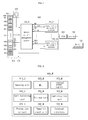
- FIG. 8 is a flow chart illustrating a method for driving a battery management system according to another embodiment of the present invention.
- the battery management system includes a master battery management system and at least one slave battery management system.
- a driving method of the master battery management system according to another embodiment will be primarily explained below. Unless otherwise stated, all operations are done by the master battery management system in the below description. All reference numerals are omitted because an explanation relating to the method is given.
- the method according to another embodiment of the present invention includes the following steps: determination of a ready signal (S1); outputting of a synchronization start signal (S2); outputting of a synchronization reset signal (S3); determination of a synchronization check signal (S4); and outputting of a system fault signal (S5).
- step S1 it is determined whether a ready signal is inputted from the slave battery management system.
- the slave battery management system outputs the ready signal to the master battery management system when the internal power is on.
- a synchronization start signal is outputted to the slave battery management system.
- the master battery management system operates its internal timer while also (e.g., concurrently) outputting the synchronization start signal.
- the slave battery management system also operates their respective internal timers in response to the synchronization start signal. It is to be understood that clock frequencies outputted from the timers of the master battery management system and the slave battery management system have the same value. Further, the two clock frequencies start at the same point (i.e., the clocks have the same phase).
- step S3 a synchronization reset signal is outputted to the slave battery management system.
- the master battery management system periodically outputs the synchronization reset signal.
- the clock of the timer included in the slave battery management system is forcibly reset to a reference time (e.g., predetermined time) in response to the synchronization reset signal.
- the reference time e.g., the predetermined time
- the reference time refers to the time at which the clock frequencies of the timers of the master battery management system and the slave battery management system have the same phase. For example, when the clock of the timer of the master battery management system starts at 9.5 ms, the clock of the timer of the slave battery management system also starts at 9.5 ms, which may be adjusted by forced holding or dragging.
- Step S3 is carried out at the time when no sensing operation is performed in order to avoid disturbance to the voltage, current and temperature sensing of the battery cells.
- step S4 it is determined whether a synchronization check signal is inputted from the slave battery management system.
- the synchronization check signal may be selected from battery voltage control signals for detecting the battery voltage. That is, the synchronization check signal may be one of the voltage control signals outputted from the slave battery management system to detect the voltage of the corresponding battery cell.
- the synchronization check signal is inputted from the slave battery management system and has the same phase as a voltage control signal outputted from the master battery management system, it can be determined that the master battery management system is precisely synchronized with the slave battery management system.
- step S5 a system fault signal is outputted when the synchronization check signal is not inputted from the slave battery management system or the inputted synchronization check signal has a phase different from that of the voltage control signal outputted from the master battery management system.
- the system fault signal may be transmitted to the MTCU of the vehicle or may be directly outputted on a display to inform a user of the fault.
- the synchronization reset signal is periodically outputted from the master battery management system to the slave battery management system to forcibly match the synchronization time of the master battery management system and the synchronization time of the slave battery management system. Therefore, the validity and reliability of the measured values, such as the voltage, current and temperature values of the battery cell, and the calculated values therefrom are improved.
- the time delay of the timers is prevented or reduced by software as well as hardware, thus ensuring better performance of the battery management system.
- the master battery management system and the slave battery management system precisely synchronize synchronization signals by software as well as hardware.
Landscapes
- Engineering & Computer Science (AREA)
- Chemical & Material Sciences (AREA)
- Mechanical Engineering (AREA)
- Manufacturing & Machinery (AREA)
- Chemical Kinetics & Catalysis (AREA)
- Electrochemistry (AREA)
- General Chemical & Material Sciences (AREA)
- Transportation (AREA)
- General Physics & Mathematics (AREA)
- Combustion & Propulsion (AREA)
- Physics & Mathematics (AREA)
- Microelectronics & Electronic Packaging (AREA)
- Automation & Control Theory (AREA)
- Charge And Discharge Circuits For Batteries Or The Like (AREA)
- Secondary Cells (AREA)
- Tests Of Electric Status Of Batteries (AREA)
- Electric Propulsion And Braking For Vehicles (AREA)
Applications Claiming Priority (1)
| Application Number | Priority Date | Filing Date | Title |
|---|---|---|---|
| KR1020090043547A KR101016813B1 (ko) | 2009-05-19 | 2009-05-19 | 배터리 관리 시스템 및 그 구동 방법 |
Publications (2)
| Publication Number | Publication Date |
|---|---|
| EP2254189A1 true EP2254189A1 (de) | 2010-11-24 |
| EP2254189B1 EP2254189B1 (de) | 2014-07-30 |
Family
ID=42359516
Family Applications (1)
| Application Number | Title | Priority Date | Filing Date |
|---|---|---|---|
| EP10163238.8A Active EP2254189B1 (de) | 2009-05-19 | 2010-05-19 | System und Antriebsverfahren zur Batterieverwaltung |
Country Status (5)
| Country | Link |
|---|---|
| US (1) | US8307223B2 (de) |
| EP (1) | EP2254189B1 (de) |
| JP (1) | JP5330203B2 (de) |
| KR (1) | KR101016813B1 (de) |
| CN (1) | CN101895133B (de) |
Cited By (4)
| Publication number | Priority date | Publication date | Assignee | Title |
|---|---|---|---|---|
| EP2690748A2 (de) * | 2011-05-31 | 2014-01-29 | LG Chem, Ltd. | Energiespeichervorrichtung, energiespeichersystem damit und verfahren zum konfigurieren des energiespeichersystems |
| EP2919346A4 (de) * | 2013-10-07 | 2016-08-10 | Lg Chemical Ltd | Vorrichtung und verfahren zur verwaltung einer batterie, einschliesslich eines fehlfunktionsvermeidungsalgorithmus |
| EP3024166A4 (de) * | 2013-10-16 | 2017-03-15 | LG Chem, Ltd. | Kommunikationssystem mit synchronisierten einheiten und synchronisationsverfahren für einheiten |
| CN113795998A (zh) * | 2019-06-18 | 2021-12-14 | 株式会社Lg新能源 | 电池管理系统和电池管理方法 |
Families Citing this family (46)
| Publication number | Priority date | Publication date | Assignee | Title |
|---|---|---|---|---|
| JP2001027971A (ja) * | 1999-07-15 | 2001-01-30 | Nippon Telegr & Teleph Corp <Ntt> | ディジタルデータ記憶装置 |
| KR100995075B1 (ko) * | 2008-08-26 | 2010-11-18 | 삼성에스디아이 주식회사 | 배터리 관리 시스템 및 그 구동 방법 |
| KR101360825B1 (ko) * | 2009-12-21 | 2014-02-10 | 에스케이이노베이션 주식회사 | 하이브리드 차량용 고전압 배터리 관리 장치 |
| US8659261B2 (en) * | 2010-07-14 | 2014-02-25 | Sinoelectric Powertrain Corporation | Battery pack enumeration method |
| CN102623760A (zh) * | 2011-01-26 | 2012-08-01 | 上海樟村电子有限公司 | 一种电池管理系统 |
| US9885757B2 (en) * | 2011-04-01 | 2018-02-06 | Atieva, Inc. | Method and apparatus for determining the state-of-charge of a battery |
| WO2012144674A1 (ko) * | 2011-04-22 | 2012-10-26 | Sk 이노베이션 주식회사 | 착탈 가능한 배터리 모듈, 이를 이용한 배터리 스트링을 위한 전하 균일 방법 및 장치 |
| KR101255248B1 (ko) * | 2011-07-04 | 2013-04-16 | 로베르트 보쉬 게엠베하 | 배터리 관리 시스템 및 이의 제어 방법 |
| KR20130061814A (ko) * | 2011-12-02 | 2013-06-12 | 삼성에스디아이 주식회사 | 배터리 전압 측정회로 및 이를 구비한 전력 저장 시스템 |
| KR101539689B1 (ko) * | 2012-02-20 | 2015-07-27 | 주식회사 엘지화학 | 멀티 bms에 대한 식별자 할당 시스템 및 방법 |
| US9300140B2 (en) * | 2012-06-28 | 2016-03-29 | General Electric Company | System and method for design and optimization of grid connected photovoltaic power plant with multiple photovoltaic module technologies |
| KR101926196B1 (ko) * | 2012-07-09 | 2018-12-06 | 에스케이이노베이션 주식회사 | 병렬 팩 배터리 시스템의 장애 관리 장치 및 그 방법 |
| CN103580089B (zh) | 2012-07-25 | 2017-07-21 | 现代摩比斯株式会社 | 分布式电池管理系统及分布式电池管理方法 |
| US9300016B2 (en) | 2012-09-14 | 2016-03-29 | Samsung Sdi Co., Ltd. | Battery system and energy storage system |
| US9217781B2 (en) * | 2014-01-16 | 2015-12-22 | Ford Global Technologies, Llc | Time synchronization between battery controller modules for parameter measurements |
| US9056556B1 (en) | 2014-02-25 | 2015-06-16 | Elwha Llc | System and method for configuration and management of an energy storage system for a vehicle |
| US9079505B1 (en) | 2014-02-25 | 2015-07-14 | Elwah LLC | System and method for management of a fleet of vehicles having an energy storage system |
| US9878631B2 (en) | 2014-02-25 | 2018-01-30 | Elwha Llc | System and method for predictive control of an energy storage system for a vehicle |
| KR101754948B1 (ko) * | 2014-10-07 | 2017-07-06 | 주식회사 엘지화학 | 배터리 관리 모듈의 통신 id 할당 방법 및 시스템 |
| KR101584261B1 (ko) | 2014-11-17 | 2016-01-21 | 현대오트론 주식회사 | 배터리 관리 시스템 및 방법 |
| KR102299448B1 (ko) * | 2014-11-24 | 2021-09-08 | 현대모비스 주식회사 | 배터리 브리지에 장착되는 배터리 센서 및 이를 이용한 전압 센싱 방법 |
| KR102337489B1 (ko) * | 2015-01-08 | 2021-12-09 | 삼성에스디아이 주식회사 | 전기차량의 배터리 soh 추정 시스템 |
| KR101863700B1 (ko) * | 2015-02-24 | 2018-06-01 | 주식회사 엘지화학 | 배터리 관리 장치 |
| KR101779655B1 (ko) * | 2015-02-26 | 2017-09-18 | 엘에스산전 주식회사 | 에너지 저장 시스템의 동기화 방법 |
| KR101739181B1 (ko) | 2015-04-27 | 2017-05-23 | 엘에스산전 주식회사 | 에너지 저장 시스템 |
| CN105044607B (zh) * | 2015-07-01 | 2018-06-26 | 中国电力科学研究院 | 一种电池模组多通道同步检测装置 |
| CN105226759A (zh) * | 2015-10-28 | 2016-01-06 | 北京新能源汽车股份有限公司 | 电池管理系统的同步采样方法和采样系统 |
| DE102015224067A1 (de) * | 2015-12-02 | 2017-06-08 | Borgward Trademark Holdings Gmbh | Batteriemanagementsystem, Fahrzeug damit und Verfahren zur Batterierelais-Steuerung |
| US10003214B2 (en) * | 2016-03-21 | 2018-06-19 | General Electric Company | Battery management system |
| CN107230809B (zh) * | 2016-03-24 | 2020-02-14 | 宁德时代新能源科技股份有限公司 | 电池包充电保护方法、对应的电池包和电池包充电设备 |
| US10505374B2 (en) * | 2016-05-31 | 2019-12-10 | Infineon Technologies Ag | Power balancing communication for battery management |
| JP2019101480A (ja) * | 2017-11-28 | 2019-06-24 | オムロン株式会社 | 制御装置および制御方法 |
| CN108215907B (zh) * | 2018-01-09 | 2021-09-28 | 联合汽车电子有限公司 | 电池管理系统及方法 |
| WO2019175736A1 (en) * | 2018-03-12 | 2019-09-19 | Dinesh Jaisinghani | Battery network system |
| JP7307585B2 (ja) * | 2019-04-26 | 2023-07-12 | リオン株式会社 | 時刻同期計測システム |
| US11489343B2 (en) | 2020-06-02 | 2022-11-01 | Inventus Power, Inc. | Hardware short circuit protection in a large battery pack |
| US11509144B2 (en) | 2020-06-02 | 2022-11-22 | Inventus Power, Inc. | Large-format battery management system with in-rush current protection for master-slave battery packs |
| US11552479B2 (en) | 2020-06-02 | 2023-01-10 | Inventus Power, Inc. | Battery charge balancing circuit for series connections |
| US11476677B2 (en) | 2020-06-02 | 2022-10-18 | Inventus Power, Inc. | Battery pack charge cell balancing |
| US11133690B1 (en) | 2020-06-02 | 2021-09-28 | Inventus Power, Inc. | Large-format battery management system |
| US11594892B2 (en) | 2020-06-02 | 2023-02-28 | Inventus Power, Inc. | Battery pack with series or parallel identification signal |
| US11588334B2 (en) | 2020-06-02 | 2023-02-21 | Inventus Power, Inc. | Broadcast of discharge current based on state-of-health imbalance between battery packs |
| US11245268B1 (en) | 2020-07-24 | 2022-02-08 | Inventus Power, Inc. | Mode-based disabling of communiction bus of a battery management system |
| US11404885B1 (en) | 2021-02-24 | 2022-08-02 | Inventus Power, Inc. | Large-format battery management systems with gateway PCBA |
| US11411407B1 (en) | 2021-02-24 | 2022-08-09 | Inventus Power, Inc. | Large-format battery management systems with gateway PCBA |
| JPWO2022186376A1 (de) * | 2021-03-05 | 2022-09-09 |
Citations (2)
| Publication number | Priority date | Publication date | Assignee | Title |
|---|---|---|---|---|
| JP2003017134A (ja) * | 2001-06-27 | 2003-01-17 | Osaka Gas Co Ltd | 蓄電装置の管理システム |
| EP1967408A2 (de) * | 2007-03-06 | 2008-09-10 | Hitachi Vehicle Energy, Ltd. | Batterievorrichtung, Batteriesteuervorrichtung und Motorantriebseinheit |
Family Cites Families (28)
| Publication number | Priority date | Publication date | Assignee | Title |
|---|---|---|---|---|
| JPS62128234A (ja) * | 1985-11-28 | 1987-06-10 | Fujitsu Ltd | 時分割方向制御伝送方式 |
| JPS6448144A (en) * | 1987-08-19 | 1989-02-22 | Fujitsu Ltd | Response time monitor system |
| JPH04185134A (ja) * | 1990-11-20 | 1992-07-02 | Konica Corp | データ制御装置 |
| JPH04266112A (ja) * | 1991-02-20 | 1992-09-22 | Yaskawa Electric Corp | マスタスレーブ機器間の電源投入確認方法 |
| JPH0546549A (ja) * | 1991-08-08 | 1993-02-26 | Fujitsu Ten Ltd | マイクロコンピユータ間同期式シリアル通信方式 |
| US5870025A (en) * | 1994-04-26 | 1999-02-09 | Canon Kabushiki Kaisha | Power-supply apparatus and its mounting-completion indication method |
| SE515929C2 (sv) | 1999-01-27 | 2001-10-29 | Ericsson Telefon Ab L M | Förfarande för synkronisering av kommunikationsorgan i ett batteri med kommunikationsorgan i en elektronisk utrustning, en apparat och ett batteri |
| JP4035913B2 (ja) * | 1999-03-18 | 2008-01-23 | 株式会社デンソー | 組み電池の充電状態検出装置および該装置を用いた車両制御装置 |
| JP3405526B2 (ja) * | 1999-04-02 | 2003-05-12 | エヌイーシートーキン栃木株式会社 | 複数電池パック電源装置 |
| DE60021066T2 (de) * | 2000-07-07 | 2006-05-18 | Sun Microsystems, Inc., Santa Clara | Prüfung eines Softwarepakets |
| US6629257B1 (en) * | 2000-08-31 | 2003-09-30 | Hewlett-Packard Development Company, L.P. | System and method to automatically reset and initialize a clocking subsystem with reset signaling technique |
| JP3936179B2 (ja) * | 2001-11-30 | 2007-06-27 | パナソニック・イーブイ・エナジー株式会社 | 電池電源装置とその電流検出方法 |
| JP2002374633A (ja) * | 2001-06-14 | 2002-12-26 | Osaka Gas Co Ltd | 蓄電装置 |
| US6976470B2 (en) * | 2001-08-08 | 2005-12-20 | Hitachi, Ltd. | Device for controlling throttle valve |
| US6768286B2 (en) * | 2002-08-20 | 2004-07-27 | Lsi Logic Corporation | Battery charger system and method for providing detailed battery status and charging method information about multiple batteries |
| US7085948B2 (en) | 2003-04-24 | 2006-08-01 | International Business Machines Corporation | Method, apparatus, and computer program product for implementing time synchronization correction in computer systems |
| JP4241343B2 (ja) * | 2003-11-26 | 2009-03-18 | 富士電機システムズ株式会社 | 送信タイミング決定方法、バス使用権の調停方法、ネットワークシステム、プログラム |
| CN101741117B (zh) * | 2004-12-24 | 2014-01-01 | Lg化学株式会社 | 电池平衡的系统及其方法 |
| JP4096951B2 (ja) * | 2005-03-28 | 2008-06-04 | 松下電工株式会社 | 電気機器 |
| US7536194B2 (en) | 2005-09-30 | 2009-05-19 | Robert Bosch Gmbh | Method and system for providing an energy efficient exchange of information in wireless networks |
| WO2007046657A1 (en) * | 2005-10-21 | 2007-04-26 | Lg Chem, Ltd. | Multi-battery pack system, method for controlling the same, and battery pack |
| KR100991084B1 (ko) | 2005-12-15 | 2010-10-29 | 주식회사 엘지화학 | 멀티 전지 팩 시스템 및 그 제어방법, 및 이를 이용한 전지팩 |
| JP4928864B2 (ja) | 2006-08-11 | 2012-05-09 | 株式会社オサシ・テクノス | ネットワークシステム |
| US8122275B2 (en) * | 2006-08-24 | 2012-02-21 | Altera Corporation | Write-leveling implementation in programmable logic devices |
| KR100906907B1 (ko) | 2006-10-10 | 2009-07-08 | 현대자동차주식회사 | 자동차 배터리 관리 시스템 |
| JP4919489B2 (ja) * | 2007-01-17 | 2012-04-18 | パナソニック株式会社 | 通過管理システム |
| JP2008245271A (ja) * | 2007-03-01 | 2008-10-09 | Yaskawa Electric Corp | Ieee1394同期通信システムおよび同期通信方法 |
| US7619449B2 (en) * | 2007-06-07 | 2009-11-17 | Micron Technology, Inc. | Method and apparatus for synchronous clock distribution to a plurality of destinations |
-
2009
- 2009-05-19 KR KR1020090043547A patent/KR101016813B1/ko active IP Right Grant
- 2009-11-25 JP JP2009267627A patent/JP5330203B2/ja active Active
- 2009-12-02 US US12/629,866 patent/US8307223B2/en active Active
-
2010
- 2010-05-11 CN CN2010101769499A patent/CN101895133B/zh active Active
- 2010-05-19 EP EP10163238.8A patent/EP2254189B1/de active Active
Patent Citations (2)
| Publication number | Priority date | Publication date | Assignee | Title |
|---|---|---|---|---|
| JP2003017134A (ja) * | 2001-06-27 | 2003-01-17 | Osaka Gas Co Ltd | 蓄電装置の管理システム |
| EP1967408A2 (de) * | 2007-03-06 | 2008-09-10 | Hitachi Vehicle Energy, Ltd. | Batterievorrichtung, Batteriesteuervorrichtung und Motorantriebseinheit |
Cited By (10)
| Publication number | Priority date | Publication date | Assignee | Title |
|---|---|---|---|---|
| EP2690748A2 (de) * | 2011-05-31 | 2014-01-29 | LG Chem, Ltd. | Energiespeichervorrichtung, energiespeichersystem damit und verfahren zum konfigurieren des energiespeichersystems |
| CN103563209A (zh) * | 2011-05-31 | 2014-02-05 | 株式会社Lg化学 | 电力储存装置、利用其的电力储存系统、以及用于构成电力储存系统的方法 |
| EP2690748A4 (de) * | 2011-05-31 | 2014-11-05 | Lg Chemical Ltd | Energiespeichervorrichtung, energiespeichersystem damit und verfahren zum konfigurieren des energiespeichersystems |
| CN103563209B (zh) * | 2011-05-31 | 2017-02-08 | 株式会社Lg化学 | 电力储存装置、利用其的电力储存系统、以及用于构成电力储存系统的方法 |
| EP2919346A4 (de) * | 2013-10-07 | 2016-08-10 | Lg Chemical Ltd | Vorrichtung und verfahren zur verwaltung einer batterie, einschliesslich eines fehlfunktionsvermeidungsalgorithmus |
| US9564764B2 (en) | 2013-10-07 | 2017-02-07 | Lg Chem, Ltd. | Apparatus and method for battery management with malfunction prevention algorithm |
| EP3024166A4 (de) * | 2013-10-16 | 2017-03-15 | LG Chem, Ltd. | Kommunikationssystem mit synchronisierten einheiten und synchronisationsverfahren für einheiten |
| CN113795998A (zh) * | 2019-06-18 | 2021-12-14 | 株式会社Lg新能源 | 电池管理系统和电池管理方法 |
| CN113795998B (zh) * | 2019-06-18 | 2024-03-29 | 株式会社Lg新能源 | 电池管理系统和电池管理方法 |
| US11984750B2 (en) | 2019-06-18 | 2024-05-14 | Lg Energy Solution, Ltd. | Battery management system and battery management method |
Also Published As
| Publication number | Publication date |
|---|---|
| KR20100124499A (ko) | 2010-11-29 |
| EP2254189B1 (de) | 2014-07-30 |
| US8307223B2 (en) | 2012-11-06 |
| CN101895133B (zh) | 2013-04-17 |
| JP5330203B2 (ja) | 2013-10-30 |
| JP2010273530A (ja) | 2010-12-02 |
| US20100295382A1 (en) | 2010-11-25 |
| KR101016813B1 (ko) | 2011-02-21 |
| CN101895133A (zh) | 2010-11-24 |
Similar Documents
| Publication | Publication Date | Title |
|---|---|---|
| EP2254189B1 (de) | System und Antriebsverfahren zur Batterieverwaltung | |
| JP5259338B2 (ja) | バッテリー管理システム及びその駆動方法 | |
| KR101041124B1 (ko) | 배터리 관리 시스템 및 그 구동 방법 | |
| JP5250230B2 (ja) | 車両用電源システムおよび電池セル制御用集積回路 | |
| JP5459946B2 (ja) | 車両用直流電源装置 | |
| JP5127383B2 (ja) | 電池用集積回路および該電池用集積回路を使用した車両用電源システム | |
| JP5386075B2 (ja) | 多直列電池制御システム | |
| JP5647210B2 (ja) | 電池セル用集積回路 | |
| EP2360485B1 (de) | Batterieverwaltungssystem und Antriebsverfahren dafür | |
| US8264201B2 (en) | Battery management system and driving method thereof | |
| US20110049977A1 (en) | Safety and performance optimized controls for large scale electric vehicle battery systems | |
| JP5940601B2 (ja) | 電池システムおよび電池制御装置 |
Legal Events
| Date | Code | Title | Description |
|---|---|---|---|
| PUAI | Public reference made under article 153(3) epc to a published international application that has entered the european phase |
Free format text: ORIGINAL CODE: 0009012 |
|
| 17P | Request for examination filed |
Effective date: 20100519 |
|
| AK | Designated contracting states |
Kind code of ref document: A1 Designated state(s): AL AT BE BG CH CY CZ DE DK EE ES FI FR GB GR HR HU IE IS IT LI LT LU LV MC MK MT NL NO PL PT RO SE SI SK SM TR |
|
| AX | Request for extension of the european patent |
Extension state: BA ME RS |
|
| 17Q | First examination report despatched |
Effective date: 20110517 |
|
| RAP1 | Party data changed (applicant data changed or rights of an application transferred) |
Owner name: SAMSUNG SDI CO., LTD. Owner name: ROBERT BOSCH GMBH |
|
| RIC1 | Information provided on ipc code assigned before grant |
Ipc: G01R 31/36 20060101ALI20140109BHEP Ipc: H01M 10/42 20060101AFI20140109BHEP Ipc: H01M 6/50 20060101ALN20140109BHEP Ipc: H01M 10/48 20060101ALN20140109BHEP |
|
| RIC1 | Information provided on ipc code assigned before grant |
Ipc: G01R 31/36 20060101ALI20140110BHEP Ipc: H01M 10/42 20060101AFI20140110BHEP Ipc: H01M 10/48 20060101ALN20140110BHEP Ipc: H01M 6/50 20060101ALN20140110BHEP |
|
| GRAP | Despatch of communication of intention to grant a patent |
Free format text: ORIGINAL CODE: EPIDOSNIGR1 |
|
| INTG | Intention to grant announced |
Effective date: 20140318 |
|
| RIN1 | Information on inventor provided before grant (corrected) |
Inventor name: TAE, YONGJUN Inventor name: MURAKAMI, YUSAI |
|
| GRAS | Grant fee paid |
Free format text: ORIGINAL CODE: EPIDOSNIGR3 |
|
| GRAA | (expected) grant |
Free format text: ORIGINAL CODE: 0009210 |
|
| AK | Designated contracting states |
Kind code of ref document: B1 Designated state(s): AL AT BE BG CH CY CZ DE DK EE ES FI FR GB GR HR HU IE IS IT LI LT LU LV MC MK MT NL NO PL PT RO SE SI SK SM TR |
|
| REG | Reference to a national code |
Ref country code: GB Ref legal event code: FG4D |
|
| REG | Reference to a national code |
Ref country code: CH Ref legal event code: EP |
|
| REG | Reference to a national code |
Ref country code: AT Ref legal event code: REF Ref document number: 680342 Country of ref document: AT Kind code of ref document: T Effective date: 20140815 |
|
| REG | Reference to a national code |
Ref country code: IE Ref legal event code: FG4D |
|
| REG | Reference to a national code |
Ref country code: DE Ref legal event code: R096 Ref document number: 602010017845 Country of ref document: DE Effective date: 20140911 |
|
| REG | Reference to a national code |
Ref country code: AT Ref legal event code: MK05 Ref document number: 680342 Country of ref document: AT Kind code of ref document: T Effective date: 20140730 |
|
| REG | Reference to a national code |
Ref country code: NL Ref legal event code: VDEP Effective date: 20140730 |
|
| REG | Reference to a national code |
Ref country code: LT Ref legal event code: MG4D |
|
| PG25 | Lapsed in a contracting state [announced via postgrant information from national office to epo] |
Ref country code: ES Free format text: LAPSE BECAUSE OF FAILURE TO SUBMIT A TRANSLATION OF THE DESCRIPTION OR TO PAY THE FEE WITHIN THE PRESCRIBED TIME-LIMIT Effective date: 20140730 Ref country code: BG Free format text: LAPSE BECAUSE OF FAILURE TO SUBMIT A TRANSLATION OF THE DESCRIPTION OR TO PAY THE FEE WITHIN THE PRESCRIBED TIME-LIMIT Effective date: 20141030 Ref country code: PT Free format text: LAPSE BECAUSE OF FAILURE TO SUBMIT A TRANSLATION OF THE DESCRIPTION OR TO PAY THE FEE WITHIN THE PRESCRIBED TIME-LIMIT Effective date: 20141202 Ref country code: SE Free format text: LAPSE BECAUSE OF FAILURE TO SUBMIT A TRANSLATION OF THE DESCRIPTION OR TO PAY THE FEE WITHIN THE PRESCRIBED TIME-LIMIT Effective date: 20140730 Ref country code: GR Free format text: LAPSE BECAUSE OF FAILURE TO SUBMIT A TRANSLATION OF THE DESCRIPTION OR TO PAY THE FEE WITHIN THE PRESCRIBED TIME-LIMIT Effective date: 20141031 Ref country code: NO Free format text: LAPSE BECAUSE OF FAILURE TO SUBMIT A TRANSLATION OF THE DESCRIPTION OR TO PAY THE FEE WITHIN THE PRESCRIBED TIME-LIMIT Effective date: 20141030 Ref country code: FI Free format text: LAPSE BECAUSE OF FAILURE TO SUBMIT A TRANSLATION OF THE DESCRIPTION OR TO PAY THE FEE WITHIN THE PRESCRIBED TIME-LIMIT Effective date: 20140730 Ref country code: LT Free format text: LAPSE BECAUSE OF FAILURE TO SUBMIT A TRANSLATION OF THE DESCRIPTION OR TO PAY THE FEE WITHIN THE PRESCRIBED TIME-LIMIT Effective date: 20140730 |
|
| PG25 | Lapsed in a contracting state [announced via postgrant information from national office to epo] |
Ref country code: IS Free format text: LAPSE BECAUSE OF FAILURE TO SUBMIT A TRANSLATION OF THE DESCRIPTION OR TO PAY THE FEE WITHIN THE PRESCRIBED TIME-LIMIT Effective date: 20141130 Ref country code: PL Free format text: LAPSE BECAUSE OF FAILURE TO SUBMIT A TRANSLATION OF THE DESCRIPTION OR TO PAY THE FEE WITHIN THE PRESCRIBED TIME-LIMIT Effective date: 20140730 Ref country code: CY Free format text: LAPSE BECAUSE OF FAILURE TO SUBMIT A TRANSLATION OF THE DESCRIPTION OR TO PAY THE FEE WITHIN THE PRESCRIBED TIME-LIMIT Effective date: 20140730 Ref country code: LV Free format text: LAPSE BECAUSE OF FAILURE TO SUBMIT A TRANSLATION OF THE DESCRIPTION OR TO PAY THE FEE WITHIN THE PRESCRIBED TIME-LIMIT Effective date: 20140730 Ref country code: AT Free format text: LAPSE BECAUSE OF FAILURE TO SUBMIT A TRANSLATION OF THE DESCRIPTION OR TO PAY THE FEE WITHIN THE PRESCRIBED TIME-LIMIT Effective date: 20140730 Ref country code: HR Free format text: LAPSE BECAUSE OF FAILURE TO SUBMIT A TRANSLATION OF THE DESCRIPTION OR TO PAY THE FEE WITHIN THE PRESCRIBED TIME-LIMIT Effective date: 20140730 Ref country code: NL Free format text: LAPSE BECAUSE OF FAILURE TO SUBMIT A TRANSLATION OF THE DESCRIPTION OR TO PAY THE FEE WITHIN THE PRESCRIBED TIME-LIMIT Effective date: 20140730 |
|
| PG25 | Lapsed in a contracting state [announced via postgrant information from national office to epo] |
Ref country code: RO Free format text: LAPSE BECAUSE OF FAILURE TO SUBMIT A TRANSLATION OF THE DESCRIPTION OR TO PAY THE FEE WITHIN THE PRESCRIBED TIME-LIMIT Effective date: 20140730 Ref country code: IT Free format text: LAPSE BECAUSE OF FAILURE TO SUBMIT A TRANSLATION OF THE DESCRIPTION OR TO PAY THE FEE WITHIN THE PRESCRIBED TIME-LIMIT Effective date: 20140730 Ref country code: CZ Free format text: LAPSE BECAUSE OF FAILURE TO SUBMIT A TRANSLATION OF THE DESCRIPTION OR TO PAY THE FEE WITHIN THE PRESCRIBED TIME-LIMIT Effective date: 20140730 Ref country code: EE Free format text: LAPSE BECAUSE OF FAILURE TO SUBMIT A TRANSLATION OF THE DESCRIPTION OR TO PAY THE FEE WITHIN THE PRESCRIBED TIME-LIMIT Effective date: 20140730 Ref country code: SK Free format text: LAPSE BECAUSE OF FAILURE TO SUBMIT A TRANSLATION OF THE DESCRIPTION OR TO PAY THE FEE WITHIN THE PRESCRIBED TIME-LIMIT Effective date: 20140730 Ref country code: DK Free format text: LAPSE BECAUSE OF FAILURE TO SUBMIT A TRANSLATION OF THE DESCRIPTION OR TO PAY THE FEE WITHIN THE PRESCRIBED TIME-LIMIT Effective date: 20140730 |
|
| REG | Reference to a national code |
Ref country code: DE Ref legal event code: R097 Ref document number: 602010017845 Country of ref document: DE |
|
| PLBE | No opposition filed within time limit |
Free format text: ORIGINAL CODE: 0009261 |
|
| STAA | Information on the status of an ep patent application or granted ep patent |
Free format text: STATUS: NO OPPOSITION FILED WITHIN TIME LIMIT |
|
| 26N | No opposition filed |
Effective date: 20150504 |
|
| PG25 | Lapsed in a contracting state [announced via postgrant information from national office to epo] |
Ref country code: SI Free format text: LAPSE BECAUSE OF FAILURE TO SUBMIT A TRANSLATION OF THE DESCRIPTION OR TO PAY THE FEE WITHIN THE PRESCRIBED TIME-LIMIT Effective date: 20140730 |
|
| REG | Reference to a national code |
Ref country code: CH Ref legal event code: PL |
|
| PG25 | Lapsed in a contracting state [announced via postgrant information from national office to epo] |
Ref country code: LU Free format text: LAPSE BECAUSE OF FAILURE TO SUBMIT A TRANSLATION OF THE DESCRIPTION OR TO PAY THE FEE WITHIN THE PRESCRIBED TIME-LIMIT Effective date: 20150519 Ref country code: MC Free format text: LAPSE BECAUSE OF FAILURE TO SUBMIT A TRANSLATION OF THE DESCRIPTION OR TO PAY THE FEE WITHIN THE PRESCRIBED TIME-LIMIT Effective date: 20140730 Ref country code: LI Free format text: LAPSE BECAUSE OF NON-PAYMENT OF DUE FEES Effective date: 20150531 Ref country code: CH Free format text: LAPSE BECAUSE OF NON-PAYMENT OF DUE FEES Effective date: 20150531 |
|
| REG | Reference to a national code |
Ref country code: IE Ref legal event code: MM4A |
|
| REG | Reference to a national code |
Ref country code: FR Ref legal event code: PLFP Year of fee payment: 7 |
|
| PG25 | Lapsed in a contracting state [announced via postgrant information from national office to epo] |
Ref country code: IE Free format text: LAPSE BECAUSE OF NON-PAYMENT OF DUE FEES Effective date: 20150519 |
|
| PG25 | Lapsed in a contracting state [announced via postgrant information from national office to epo] |
Ref country code: BE Free format text: LAPSE BECAUSE OF FAILURE TO SUBMIT A TRANSLATION OF THE DESCRIPTION OR TO PAY THE FEE WITHIN THE PRESCRIBED TIME-LIMIT Effective date: 20140730 |
|
| PG25 | Lapsed in a contracting state [announced via postgrant information from national office to epo] |
Ref country code: MT Free format text: LAPSE BECAUSE OF FAILURE TO SUBMIT A TRANSLATION OF THE DESCRIPTION OR TO PAY THE FEE WITHIN THE PRESCRIBED TIME-LIMIT Effective date: 20140730 |
|
| REG | Reference to a national code |
Ref country code: FR Ref legal event code: PLFP Year of fee payment: 8 |
|
| PG25 | Lapsed in a contracting state [announced via postgrant information from national office to epo] |
Ref country code: HU Free format text: LAPSE BECAUSE OF FAILURE TO SUBMIT A TRANSLATION OF THE DESCRIPTION OR TO PAY THE FEE WITHIN THE PRESCRIBED TIME-LIMIT; INVALID AB INITIO Effective date: 20100519 Ref country code: SM Free format text: LAPSE BECAUSE OF FAILURE TO SUBMIT A TRANSLATION OF THE DESCRIPTION OR TO PAY THE FEE WITHIN THE PRESCRIBED TIME-LIMIT Effective date: 20140730 |
|
| PG25 | Lapsed in a contracting state [announced via postgrant information from national office to epo] |
Ref country code: TR Free format text: LAPSE BECAUSE OF FAILURE TO SUBMIT A TRANSLATION OF THE DESCRIPTION OR TO PAY THE FEE WITHIN THE PRESCRIBED TIME-LIMIT Effective date: 20140730 |
|
| REG | Reference to a national code |
Ref country code: FR Ref legal event code: PLFP Year of fee payment: 9 |
|
| PG25 | Lapsed in a contracting state [announced via postgrant information from national office to epo] |
Ref country code: MK Free format text: LAPSE BECAUSE OF FAILURE TO SUBMIT A TRANSLATION OF THE DESCRIPTION OR TO PAY THE FEE WITHIN THE PRESCRIBED TIME-LIMIT Effective date: 20140730 |
|
| PG25 | Lapsed in a contracting state [announced via postgrant information from national office to epo] |
Ref country code: AL Free format text: LAPSE BECAUSE OF FAILURE TO SUBMIT A TRANSLATION OF THE DESCRIPTION OR TO PAY THE FEE WITHIN THE PRESCRIBED TIME-LIMIT Effective date: 20140730 |
|
| P01 | Opt-out of the competence of the unified patent court (upc) registered |
Effective date: 20230530 |
|
| PGFP | Annual fee paid to national office [announced via postgrant information from national office to epo] |
Ref country code: FR Payment date: 20230421 Year of fee payment: 14 Ref country code: DE Payment date: 20230425 Year of fee payment: 14 |
|
| PGFP | Annual fee paid to national office [announced via postgrant information from national office to epo] |
Ref country code: GB Payment date: 20230427 Year of fee payment: 14 |