EP2252000A2 - Dispositif de transmission et réception WDM optique et unité d'émission-réception optique correspondante - Google Patents
Dispositif de transmission et réception WDM optique et unité d'émission-réception optique correspondante Download PDFInfo
- Publication number
- EP2252000A2 EP2252000A2 EP10002951A EP10002951A EP2252000A2 EP 2252000 A2 EP2252000 A2 EP 2252000A2 EP 10002951 A EP10002951 A EP 10002951A EP 10002951 A EP10002951 A EP 10002951A EP 2252000 A2 EP2252000 A2 EP 2252000A2
- Authority
- EP
- European Patent Office
- Prior art keywords
- unit
- optical
- signal
- tuning
- channel
- Prior art date
- Legal status (The legal status is an assumption and is not a legal conclusion. Google has not performed a legal analysis and makes no representation as to the accuracy of the status listed.)
- Granted
Links
- 230000003287 optical effect Effects 0.000 title claims abstract description 183
- 230000005540 biological transmission Effects 0.000 title claims description 77
- 238000003780 insertion Methods 0.000 claims description 4
- 230000037431 insertion Effects 0.000 claims description 4
- 230000007704 transition Effects 0.000 abstract 1
- 238000009434 installation Methods 0.000 description 4
- 238000011896 sensitive detection Methods 0.000 description 2
- 230000004888 barrier function Effects 0.000 description 1
- 230000007175 bidirectional communication Effects 0.000 description 1
- 230000002457 bidirectional effect Effects 0.000 description 1
- 230000001419 dependent effect Effects 0.000 description 1
- 238000010586 diagram Methods 0.000 description 1
- 238000000034 method Methods 0.000 description 1
- 230000000737 periodic effect Effects 0.000 description 1
- 230000001960 triggered effect Effects 0.000 description 1
Images
Classifications
-
- H—ELECTRICITY
- H04—ELECTRIC COMMUNICATION TECHNIQUE
- H04J—MULTIPLEX COMMUNICATION
- H04J14/00—Optical multiplex systems
- H04J14/02—Wavelength-division multiplex systems
- H04J14/0227—Operation, administration, maintenance or provisioning [OAMP] of WDM networks, e.g. media access, routing or wavelength allocation
- H04J14/0254—Optical medium access
- H04J14/0256—Optical medium access at the optical channel layer
- H04J14/0257—Wavelength assignment algorithms
-
- H—ELECTRICITY
- H04—ELECTRIC COMMUNICATION TECHNIQUE
- H04J—MULTIPLEX COMMUNICATION
- H04J14/00—Optical multiplex systems
- H04J14/02—Wavelength-division multiplex systems
- H04J14/0227—Operation, administration, maintenance or provisioning [OAMP] of WDM networks, e.g. media access, routing or wavelength allocation
- H04J14/0254—Optical medium access
- H04J14/0256—Optical medium access at the optical channel layer
- H04J14/0258—Wavelength identification or labelling
-
- H—ELECTRICITY
- H04—ELECTRIC COMMUNICATION TECHNIQUE
- H04J—MULTIPLEX COMMUNICATION
- H04J14/00—Optical multiplex systems
- H04J14/02—Wavelength-division multiplex systems
- H04J14/03—WDM arrangements
- H04J14/0305—WDM arrangements in end terminals
Definitions
- the invention relates to an optical transceiver unit for an optical WDM transmitting and receiving device having the features of the preamble of patent claim 1. Furthermore, the invention relates to an optical WDM transmitting and receiving device with such a WDM optical transceiver unit.
- optical wavelength division multiplexing (WDM) systems are used to transmit large volumes of data.
- An optical filter unit which comprises at least one optical multiplexer unit and one optical demultiplexer unit, is provided in each case in a network node or a terminal node of a simple point-to-point connection.
- the optical multiplexer unit has a predetermined number n of channel input ports, and supplies optical channel signals supplied to the channel input ports to a WDM output port, the optical channel signals being combined into a WDM signal.
- the optical demultiplexer unit has a WDM input port to which the WDM signal to be received is supplied.
- the multiplexer unit splits the optical WDM receive signal into the individual channel signals and feeds them each to an associated channel output port.
- Each channel input port of the multiplexer unit an optical channel signal of a predetermined optical carrier wavelength can be supplied, the respective optical carrier wavelength of the supplied optical signal must correspond to the relevant channel input port channel wavelength, so that the respective optical channel signal correctly and with the lowest possible insertion loss to the WDM Output port can be supplied.
- a channel signal of a predetermined optical carrier wavelength which is to be a channel wavelength included in a received WDM optical signal may be extracted from the WDM received signal by the demultiplexer unit and supplied to the associated channel output port.
- the channel wavelengths for the transmission direction and for the reception direction are in each case selected such that the same optical channel wavelength is used for a channel i both for the transmission direction and for the reception direction.
- optical filter units usually have a multiplicity, for example 40, channel input ports or channel output ports.
- an optical transceiver unit is used in each case, which generates from a supplied electrical data signal, a corresponding optical data signal which is delivered to an optical output port of the transceiver unit.
- This optical output port of the transceiver unit is connected via an optical waveguide with the associated channel input port of the multiplexer unit of the optical filter unit.
- one channel input port of the multiplexer unit must be selected, which corresponds in terms of channel wavelength to the optical carrier wavelength of the optical signal emitted by the transceiver unit or, in other words, the carrier wavelength of the optical signal output by the transceiver unit must be the channel wavelength of the selected channel input port correspond to the multiplexer unit.
- the associated channel output port of the demultiplexer unit which is associated with the relevant channel wavelength, connected to an input port of the optical transceiver unit, which supplies in the transceiver unit, the received channel signal of a receiving unit of the transceiver unit, which is usually formed broadband so that in capable of detecting any of the possible channel signals.
- the receiving unit converts the optical channel signal into a corresponding electrical data signal and can at the same time carry out a signal processing and possibly also a signal processing.
- optical transceiver units have conventionally been provided with transmission units which have an optical transmission module of the desired channel wavelength. It was therefore necessary to provide for each channel wavelength an optical transceiver unit with the desired (fixed) channel wavelength.
- transceiver optical units have been developed with tunable transmitter modules.
- the transmission unit comprising the respective transmission module can be controlled by a controller unit such that an optical transmission signal having the desired channel wavelength is generated from the electrical data signal supplied to the transceiver unit.
- the controller unit leads the transmitting unit usually only one channel information to, ie it is determined which of several possible discrete channel wavelengths to be used for the optical transmission signal to be generated.
- transceiver units With such tunable transceiver units, it is possible to first connect a transceiver unit to any free channel input port of the multiplexer unit of an optical filter unit. Of course, the receiving unit of the transceiver unit must be connected to the associated channel output port of the demultiplexer, which is assigned the same channel wavelength. In known transceiver modules, the optical transmission unit is then supplied with the information which channel wavelength is to be used for the optical transmission signal.
- the controller unit of the optical transmission unit is not transmitted the correct information regarding the channel wavelength to be selected, for example, because during the installation of the transceiver unit, the person performing this installation has transmitted the wrong information to the controller unit.
- the necessity of correctly selecting the channel wavelength for a tunable optical transceiver unit also causes a corresponding expense.
- the multiplexer unit can not integrate the optical signal supplied to a channel input port which does not have the correct channel wavelength into the WDM signal to be transmitted.
- the invention is therefore based on the object to provide an optical transceiver unit for an optical WDM transmitting and receiving device, which as simple as possible connection of the transceiver unit to a filter unit of the optical WDM transmitting and Receiving device allows, whereby the risk of incorrect adjustment of the channel wavelength is reduced or avoided.
- the invention solves this problem with the features of patent claim 1.
- the patent claim 11 provides with its feature combination an optical WDM transmitting and receiving device with a transceiver unit designed in this way.
- the invention is based on the recognition that, in the case of a tunable optical transceiver unit, an automatic adjustment of the correct optical carrier wavelength of the channel signal to be generated by the transceiver unit can take place if the controller unit is designed in a tuning mode that matches that of the Receiver unit evaluates the received signal supplied and, depending on this, the decision is made, which channel wavelength is the correct one.
- the controller unit first controls the transmitting unit in the tuning mode in such a way that a first of the possible channel wavelengths is used for a tuning transmission signal to be generated. This transmission signal is supplied to the multiplexer unit at the respective channel input port.
- An inventive optical WDM transmitting and receiving device has an optical connection path between the WDM output port of the multiplexer unit and the WDM input port of the demultiplexer unit.
- a small part of the optical power of the WDM transmission signal is coupled out and fed to the optical reception path in the direction of the WDM input port of the demultiplexer unit by means of a further 1 ⁇ 2 coupler.
- the optical transceiver unit By means of this loop-back path it is possible for the optical transceiver unit according to the invention to determine whether the transmitted channel signal with the respective current optical carrier wavelength (channel wavelength) is actually present at the output port of the multiplexer unit, which can only be the case if the channel wavelength was correctly selected for the relevant channel input port of the multiplexer unit.
- the receiving unit of the transceiver unit detects in the tuning mode and supplies the received signal converted into an electrical signal to the controller unit.
- the controller unit uses an abort criterion (which also includes several subcriteria or several necessary prerequisites for the positive affirmation of the abort criterion may include) to finish the tuning mode after reaching the correct channel wavelength setting.
- the simplest termination criterion may be that an optical power is actually detected at this port.
- the controller unit will terminate the tuning mode as soon as it receives an optical signal (with sufficient power) from the receiving unit.
- the controller unit controls the optical transmission unit of the transceiver unit in such a way that a further of the possible channel wavelengths is used for the tuning signal to be generated. In this further step of the tuning mode, it is again detected whether the termination criterion has been met. Thus, if necessary, all available channel wavelengths are successively used for generating a corresponding tuning transmission signal, wherein the predetermined termination criterion is checked in each tuning step. If the abort criterion is met, the tuning mode is terminated and the transceiver unit can proceed to normal transmission mode.
- a tuning signal also a transmission unit of the transceiver unit supplied data signal can be used, in the tuning mode, of course, no correct bidirectional communication is possible.
- the optical transmission unit can also impart a characteristic property to the data signal supplied to it, for which purpose the transmission unit is controlled in a suitable manner by the controller unit.
- the tuning transmission signal can also be generated independently of a data signal supplied to the transmission unit, for which purpose the controller unit of the transmission unit can supply a suitable electrical tuning transmission signal.
- this identification signal can also have predetermined characteristic properties.
- the characteristic property of the identification signal or the at least one characteristic property impressed on the data signal may be a specific parameter of a modulation component, preferably a predetermined modulation frequency of an amplitude modulation.
- the controller unit can control the transmitting unit in such a way that a high-bit-rate data signal is switched on and off relatively low-frequency, the switching on and off taking place at the predetermined frequency.
- the controller unit can also supply an identification signal, which is an amplitude-modulated signal having a single or several different modulation frequencies, in the case of several modulation frequencies not being transmitted simultaneously but temporally one after the other.
- an identification signal which is an amplitude-modulated signal having a single or several different modulation frequencies, in the case of several modulation frequencies not being transmitted simultaneously but temporally one after the other.
- the transmission module of the transmitting unit in CW operation can be turned on and off relatively low frequency.
- a sinusoidal modulation of the data signal or a CW signal with a certain degree of modulation which may also be less than 100%, be made.
- a frequency or phase modulation in order to impose predetermined characteristic properties on the tuning signal.
- a certain characteristic property such as the modulation frequency of an amplitude modulation, can also be used to integrate an identifier uniquely assigned to the relevant transceiver unit into the tuning transmission signal.
- an identifier uniquely assigned to the relevant transceiver unit can also be used to integrate an identifier uniquely assigned to the relevant transceiver unit into the tuning transmission signal.
- the unique identifier may consist, for example, in a serial number of the transceiver unit or in a media access controller address assigned to the transceiver unit.
- the controller unit to check the optical signal possibly supplied to it by the receiving unit in order to determine whether this signal also has, with a sufficiently high degree of certainty, the characteristic properties which are contained in the respectively transmitted tuning transmission signal.
- the controller unit can detect the received signal supplied to it (with correct channel wavelength) in a phase-sensitive manner, so that the termination criterion can only be regarded as satisfied if the controller unit (or a lockin amplifier contained therein) ) detects a received signal with the respectively known modulation frequency.
- a fault from the opposite side of the transmission path (this may consist both in the form of a data signal and in the form of a used on the opposite side tuning signal) can also be a disturbance characterized in that on the same side of the transmission line yet another transceiver unit in Tuning mode works.
- the controller unit can determine the attenuation value between the detected received signal and the optical tuning transmission signal and additionally consider the abort criterion to be satisfied only if the attenuation value is smaller than a predefined maximum value, in the determination of which, in particular, the crosstalk attenuations of the multiplexer unit and of the demultiplexer unit of the WDM transmitting and receiving device are taken into account, and the attenuation of the optical path through which the tuning transmission signal passes until receipt by the receiving unit.
- the controller unit can also determine the attenuation value between the detected received signal and the optical tuning transmission signal and additionally consider the abort criterion as fulfilled only if the attenuation value is greater than a predefined maximum value, in the determination of which the insertion attenuations of the multiplexer unit and the Demux unit of the WDM transmitting and receiving device are taken into account as well as the attenuation of the optical path, which passes through the tuning transmission signal to the reception by the receiving unit.
- an optical modulator unit can be provided in the loop-back path of the optical WDM transmitting and receiving device, which can be controlled by a control unit of the filter unit.
- additional information can be impressed on the tuning signal.
- certain parameters of the filter unit can be transmitted to the respective transceiver unit, such as characteristics of the multiplexer unit, the demultiplexer unit, the control unit, a serial number, the number of channels and the like.
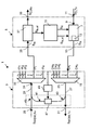
- the sole drawing shows a schematic block diagram of an optical WDM transmitting and receiving device according to the invention.
- the WDM transmitting and receiving device 1 shown in the single figure comprises an optical transceiver unit 3 and an optical filter unit 5.
- the optical transceiver unit 3 has an optical transmission unit 7, to which a data signal port 9 can supply an electrical data signal S D, Tx .
- the transceiver unit 3 can also have a data signal port 11 for this purpose.
- the optical transmission unit 7 comprises an optical transmission module 13, which is tunable with respect to its optical carrier wavelength. In the normal operating mode of operation, the optical transmission unit 7 converts the data signal S D, Tx supplied to it into a corresponding optical data signal.
- the optical transmitting unit can also perform a required Signalbe- or processing.
- a controller unit 15 of the transceiver unit 3 controls the transmitting unit 7 such that a signal having a predetermined optical carrier wavelength is output at an output port 17 of the transceiver unit 3.
- the controller unit 15 supplies the transmission unit 7 with a control signal S ⁇ i .
- the control signal is preferably such that only one channel information has to be transmitted to the transmitting unit in order to cause it to generate an optical transmission signal having a specific channel wavelength ⁇ i .
- the channel wavelength ⁇ i is one of n possible optical carrier wavelengths of optical signals, which are generated by a maximum of n transceiver units 3 and are each fed to a channel input port CH 1 to CH n of an optical multiplexer unit 19 of the optical filter unit 5.
- the output port of the transceiver unit 3 is supplied to the channel input port CH i of the multiplexer unit 19.
- further (maximum n) transceiver units may be connected to the remaining channel input ports CH 1 to CH ii and CH i + 1 to CH n .
- Each channel input port CH i of the multiplexer unit 19 is assigned a predetermined channel wavelength ⁇ i , each of the channel input ports CH 1 until CH n, only such optical signals are combined to form a WDM optical transmission signal S WDM, Tx , which have an optical carrier wavelength tuned to the respective channel wavelength ⁇ i .
- This WDM optical transmission signal S WDM, TX is supplied to the multiplexer unit 19 via an WDM output port 25 and an optical path 27 to an optical output port 21 of the optical filter unit 5 and outputted thereto to an optical transmission path (not shown).
- a received WDM optical signal S WDM, RX a WDM input port 23 of the optical filter unit 5 can be fed.
- This WDM input port 23 is connected to a WDM input port 31 of a demultiplexer unit 33 via an optical path 29, so that the WDM received signal S WDM, Rx is also supplied to the WDM input port 31 of the demultiplexer unit 33.
- the demultiplexer unit 33 again has n channel output ports, which are designated in the figure by ch i to ch n .
- Each of the channel output ports ch i to ch n is in each case assigned the same channel wavelength ⁇ 1 to ⁇ n as the respective channel input port CH 1 to CH n .
- the channel output port CH i is connected to an input port 35 of the transceiver unit 3, which in turn is connected to an input port of a receiving unit 37 which is included in the optical transceiver unit 3.
- the WDM received signal S WDM, Rx supplied to the WDM input port 23 from the connected transmission link (not shown) is supplied to the WDM input port 31 of the demultiplexer unit 33.
- the demultiplexer unit 33 demultiplexes the WDM received optical signal S WDM, Rx into the individual channel signals supplied respectively to the channel output port ch 1 to ch n having the respective channel wavelength ⁇ 1 .
- the channel signal having the channel wavelength ⁇ i is supplied to the input port 35 of the transceiver unit 3 and thus to the receiving unit 37.
- the receiving unit 37 converts the optical Channel signal in an electrical data signal S D, Rx and outputs this on a data signal port 39 of the transceiver unit 3 from.
- the controller unit 15 For correct operation of the transceiver unit 3 on the filter unit 5, it is thus necessary for the controller unit 15 to control the optical transmission unit 7 in such a way that the optical signal supplied to the respective channel input port CH i has the channel wavelength ⁇ i assigned to this port. Otherwise, the optical signal would be blocked by the multiplexer unit 19 and can not be integrated into the WDM transmit signal S WDM, Tx .
- the controller unit 15 When a transceiver unit 3 is newly connected to the optical filter unit 5, the controller unit 15 performs the functions explained below in a tuning mode.
- the tuning mode can be triggered manually or by a higher-level control unit by supplying a corresponding drive signal S T.
- the controller unit 15 must either be aware in advance of which discrete wavelengths are used by the WDM system or the WDM transceiver 1, in which the transceiver unit 3 is to be integrated. For a complete continuous tuning of the optical transmitter module would be too time consuming.
- the discrete channel wavelengths can be stored in the controller unit 15 from the outset. Of course, however, it is also possible for the controller unit 15 to supply this information via a suitable interface (not shown) from a higher-level unit.
- the controller unit 15 After the controller unit 15 has been set to the tuning mode, it first supplies the optical transmission unit 7 with a signal S ⁇ i , thereby setting a first of the possible channel wavelengths . That is, as a result of the signal S ⁇ i supplied to it , the transmitting unit 7 generates a tuning signal S ts which has the relevant channel wavelength ⁇ i .
- the tuning signal S ts can be generated in various ways: On the one hand, it is possible to use an already applied data signal S D, Tx and to convert this into a corresponding optical signal, which is then used as the tuning signal S ts . It is also possible to ignore the data signal S D, Tx and instead to turn it on to generate special, independent tuning signal.
- the controller unit 15 of the control unit 7, a corresponding electrical tuning signal S ts, el perform.
- This special tuning signal S ts, el can for example be formed as a low-frequency signal with a fixed frequency (whether sinusoidal or rectangular or with another periodic structure).
- the optical tuning signal S ts which is output at the output port 17 of the transceiver unit 3, have a corresponding time characteristic, wherein the optical carrier wavelength is determined by the signal S ⁇ l , with which the controller unit 15 controls the transmitting unit 7 ,
- the optical signal S ts, el which is a relatively low-frequency signal, can be used as a modulation signal for the high bit-rate data signal S D, Tx .
- the tuning signal S ts is not transmitted to the WDM output port 25 via the multiplexer unit 19.
- the receiving unit 37 no optical tuning received signal E ts can be detected, which could be supplied to the controller unit 15 as an optical tuning received signal E ts, el .
- the controller unit 15 controls the optical transmitting unit 7 so that a different channel wavelength; is set. This stepwise scanning is continued until the controller unit 15 detects a tuning received signal E ts , el which is supplied thereto from the optical receiving unit 37.
- the optical Receiving unit 37 is formed so that each of the selectable channel wavelengths is detectable.
- the controller unit 15 is supplied with a tuning received signal E ts, el , this fact can already be used by the controller unit 15 as a termination criterion for the loop to be passed in the tuning mode, since the controller unit 15 is in this simplest If the presence of a detected signal E ts, el with arbitrary properties can already be an indication that a signal has been transmitted via the loop-back path 41 and, consequently, the transmitting unit 7 is operating at the correct transmission wavelength or channel wavelength. Decisive in this case is only a certain minimum level for the received power of the optical signal E ts .
- the controller unit 15 preferably detects whether the tuning received signal E ts, el has a characteristic property known to it.
- the controller unit 15 can control the transmitting unit 7 in such a way that a specific special tuning signal S ts is generated which, for example, has a specific (low) fundamental frequency. If the controller unit 15 detects the same characteristic property in the tuning reception signal E ts, el supplied to it, it can be assumed with relatively high certainty that this received signal was generated by the transmission signal S ts , which is transmitted via the loop-back path 41 the receiving unit 37 has been supplied.
- the controller unit 15 detects the same characteristic property in the tuning reception signal E ts, el supplied to it, it can be assumed with relatively high certainty that this received signal was generated by the transmission signal S ts , which is transmitted via the loop-back path 41 the receiving unit 37 has been supplied.
- there are a number of different possibilities for generating corresponding characteristic properties of the tuning signal S ts which will be considered by a person skilled in the art, such as the abovementioned possibility of amplitude modulation. Further possibilities are frequency- or phase-modulated signals with certain characteristic properties
- a tuning received signal E ts el as a correct "receive signal" which can be generated, for example, by another transceiver unit 3 located in a tuning mode at the other end of the link (even if this case very unlikely)
- this signal includes the information of a unique serial number or MAC address of the transceiver unit 3 concerned. For example, if there are five digit unique serial numbers, then 10 5 different values suffice for one or more particular characteristics (or parameters) of the tuning signal. For example, 10 5 different frequency values for the amplitude modulation can be selected.
- the controller unit 15 can then not only detect that a signal is detected at a correctly selected channel wavelength ⁇ i , but also check whether the detected signal has the identifier known to it, namely the modulation frequency corresponding to the serial number.
- the respective modulation frequency can also be detected.
- the controller unit 15 can then regard the termination criterion for the tuning loop as fulfilled only if the tuning received signal E ts, el has the correct frequency corresponding to the serial number.
- the reception level for the signal E ts , el can also be checked for plausibility.
- the controller unit 15 can detect whether the reception level for the reception signal E ts is greater than a predetermined barrier. Because with an extremely sensitive detection of the received signal theoretically, a signal could be detected, which is generated by a channel signal with the wrong wavelength, wherein a corresponding received signal were generated by finite values for the crosstalk attenuation of the multiplexer unit or demultiplexer unit 19, 33.
- the security can therefore be increased if the controller unit 15 considers the termination criterion satisfied only if the tuning received signal E ts exceeds a certain reception level.
- the Controller unit 15 In order to additionally rule out that from the other end of the transmission line forth a signal is received which coincidentally has the same characteristics (of the time course) as the currently sent by the transmitting unit 7 signal S ts (but has the wrong channel wavelength), the Controller unit 15 additionally check whether the received signal S ts (or the corresponding electrical received signal E ts, el ) does not exceed a predetermined maximum level. This is determined by the predetermined insertion loss of the optical path between the output port 17 and the input port 35 of the transceiver unit 3 via the path which is defined by the loop-back path 41.
- the controller unit 15 as a characteristic properties of the received signal E ts next to its time course and the level of the received signal then check whether this is within a permissible range.
- a modulator unit 47 can be provided, which can be controlled by a control unit 49 of the filter unit 5.
- the modulator unit 49 may, as in Fig. 1 represented by the double arrow, also be connected to a higher-level control unit.
- the control unit 49 can thus impose additional information on the signal which is fed via the loop-back path 41. This information can also be received by the controller unit 15.
- These may be certain properties or characteristics of the filter unit, such as the serial number, the channel number, the carrier wavelengths of the channels, and the like.
- the controller unit 15 detects the abort criterion as fulfilled, then the tuning mode is ended. If the abort criterion is not detected in any of the individual steps of the tuning mode, for example because the input port 35 of the transceiver unit 3 is detected is not connected to the correct channel output port ch 1 to ch n , an error signal can be generated.
- Such a WDM transmitting and receiving device or such an optical transceiver unit allows the automatic setting of the correct channel wavelength, without the need for a significant intervention of an operator would be required (apart from the possibly required start of the tuning mode). This drastically reduces the possibility of errors during the commissioning of such a transceiver unit.
Landscapes
- Engineering & Computer Science (AREA)
- Computer Networks & Wireless Communication (AREA)
- Signal Processing (AREA)
- Optical Communication System (AREA)
Applications Claiming Priority (1)
| Application Number | Priority Date | Filing Date | Title |
|---|---|---|---|
| DE102009021010A DE102009021010B4 (de) | 2009-05-12 | 2009-05-12 | Optische WDM Sende- und Empfangseinrichtung und optische Transceivereinheit hierfür |
Publications (3)
| Publication Number | Publication Date |
|---|---|
| EP2252000A2 true EP2252000A2 (fr) | 2010-11-17 |
| EP2252000A3 EP2252000A3 (fr) | 2012-05-16 |
| EP2252000B1 EP2252000B1 (fr) | 2013-10-09 |
Family
ID=42105856
Family Applications (1)
| Application Number | Title | Priority Date | Filing Date |
|---|---|---|---|
| EP10002951.1A Active EP2252000B1 (fr) | 2009-05-12 | 2010-03-19 | Dispositif de transmission et réception WDM optique et unité d'émission-réception optique correspondante |
Country Status (3)
| Country | Link |
|---|---|
| US (1) | US8406630B2 (fr) |
| EP (1) | EP2252000B1 (fr) |
| DE (1) | DE102009021010B4 (fr) |
Families Citing this family (8)
| Publication number | Priority date | Publication date | Assignee | Title |
|---|---|---|---|---|
| EP2618531B1 (fr) * | 2012-01-20 | 2014-12-24 | ADVA Optical Networking SE | Procédé et dispositif pour transmettre un signal à basse fréquence sur une liaison de transmission de données à l'aide d'un signal à débit binaire élevé numérique |
| US8989591B2 (en) | 2012-06-06 | 2015-03-24 | Techsys Insights | Remote optical demarcation point |
| US9014558B2 (en) * | 2012-06-06 | 2015-04-21 | Techsys Insights | Client grooming interface |
| EP2773056B1 (fr) * | 2013-03-01 | 2018-05-09 | ADVA Optical Networking SE | Procédé permettant de régler un transmetteur optique accordable dans un système de transmission WDM optique et système de transmission WDM optique correspondant |
| CN109314578B (zh) * | 2016-06-20 | 2021-07-27 | 日本电信电话株式会社 | 光收发器以及控制方法 |
| US9900103B1 (en) * | 2016-11-02 | 2018-02-20 | Alcatel-Lucent Usa Inc. | Optical transceiver having an interface circuit with a routing capability |
| US11233585B2 (en) * | 2017-06-27 | 2022-01-25 | Kaelus Pty Ltd | System and apparatus for identifying faults in a radio frequency device or system |
| US10608774B2 (en) * | 2018-07-27 | 2020-03-31 | At&T Intellectual Property I, L.P. | Network switch and optical transponder connectivity verification for wavelength division multiplexing network |
Family Cites Families (11)
| Publication number | Priority date | Publication date | Assignee | Title |
|---|---|---|---|---|
| DE69125859T2 (de) * | 1990-01-19 | 1997-12-18 | Canon Kk | Optische Übertragungseinrichtung |
| US5592284A (en) * | 1995-04-21 | 1997-01-07 | Nortech Fibronic Inc. | Single connection automated bi-directional fiberoptic attenuation measurement system |
| US20030030875A1 (en) * | 2001-08-08 | 2003-02-13 | Tomasz Barczyk | Method for channel tagging in DWDM optical communication systems |
| AU2002226395A1 (en) * | 2001-12-27 | 2003-09-04 | Pirelli Submarine Telecom Systems Italia S.P.A. | Optical transmission system with raman amplifiers comprising a supervisory system |
| US6891995B2 (en) * | 2002-03-01 | 2005-05-10 | Matsushita Electric Industrial Co., Ltd. | Wavelength division multiplex transmission system |
| US20040047295A1 (en) * | 2002-08-20 | 2004-03-11 | Morreale Jay P. | Method and apparatus for providing a common optical line monitoring and service channel over an WDM optical transmission system |
| US7321730B2 (en) * | 2003-02-06 | 2008-01-22 | Nortel Networks Limited | Method and apparatus for the transmission fault detection in an access network |
| JP4672273B2 (ja) * | 2004-03-24 | 2011-04-20 | 富士通株式会社 | 波長多重光伝送システム及びそれにおける送信波長制御方法 |
| JP2005341529A (ja) * | 2004-04-28 | 2005-12-08 | Fujitsu Ltd | 光伝送システム,光送受信装置,光伝送装置および光波長チャンネル接続認識制御方法 |
| US8014672B2 (en) * | 2006-01-27 | 2011-09-06 | Nippon Telegraph And Telephone Corporation | Optical wavelength multiplexing access system |
| US20080089699A1 (en) * | 2006-10-17 | 2008-04-17 | Wen Li | Methods for automatic tuning optical communication system |
-
2009
- 2009-05-12 DE DE102009021010A patent/DE102009021010B4/de not_active Expired - Fee Related
-
2010
- 2010-03-19 EP EP10002951.1A patent/EP2252000B1/fr active Active
- 2010-04-28 US US12/769,381 patent/US8406630B2/en active Active
Non-Patent Citations (1)
| Title |
|---|
| None |
Also Published As
| Publication number | Publication date |
|---|---|
| US20100290785A1 (en) | 2010-11-18 |
| DE102009021010A1 (de) | 2010-11-18 |
| DE102009021010B4 (de) | 2012-03-01 |
| EP2252000B1 (fr) | 2013-10-09 |
| EP2252000A3 (fr) | 2012-05-16 |
| US8406630B2 (en) | 2013-03-26 |
Similar Documents
| Publication | Publication Date | Title |
|---|---|---|
| EP2252000B1 (fr) | Dispositif de transmission et réception WDM optique et unité d'émission-réception optique correspondante | |
| DE69605542T2 (de) | Optische mehrkanalanordnung | |
| DE69612983T2 (de) | Verbesserungen an optischen einlieferungs- und abtrennwellenlängenmultiplexsystemen | |
| DE2728686C2 (fr) | ||
| EP2254269B1 (fr) | Procédé et dispositif de protection 1+1 d'un lien de transmission optique | |
| DE602004008035T2 (de) | Optisches übertragungssystem | |
| EP0998798A1 (fr) | Procede et dispositif pour transmettre des donnees selon un procede de multiplexage en longueur d'onde dans un reseau annulaire optique | |
| DD299205A5 (de) | Faseroptische fernmeldeleitung und verstaerker fuer diese leitung | |
| EP1356619B1 (fr) | Procede et circuit electro-optique destines a la protection de ligne dans un lien de transmission de donnees wdm | |
| DE69920451T2 (de) | Verfahren und vorrichtung zur abzweigung von optischen kanälen in einem optischen übertragungssystem | |
| DE69800993T2 (de) | Verfahren und Vorrichtung zur Steuerung der optischen Leistung eines wellenlängenmultiplexierten übertragenen Signals | |
| DE69633591T2 (de) | Vorrichtung und Verfahren zur Wellenlängenregelung in einem Wellenlängenmultiplexsystem | |
| DE602005000168T2 (de) | Verfahren und Vorrichtung zu Verringerung der Effekte von PMD/PDL/PDG | |
| DE602005001317T2 (de) | Wellenlängenraster für DWDM | |
| DE60205271T2 (de) | Übertragung von optischen signalen | |
| DE69323039T2 (de) | Bidirektionale Übertragungsvorrichtung | |
| EP1498006B1 (fr) | Station de commutation optique et procede de commutation associe | |
| DE4217899C2 (de) | Verfahren zur Systemoptimierung von Lichtwellenleiter-Übertragungsstrecken | |
| DE4333367A1 (de) | Sender und Empfänger für ein optisches Nachrichtenübertragungssystem | |
| DE10004290B4 (de) | Access-Knoten für optische Netze mit variablen Access-Wellenlängen, Nutzergerät zum Anschluss an einen solchen Access-Knoten, Verfahren zum Einspeisen von mehreren Signalen von mehreren Nutzern in ein optisches Netz und Verwendung eines Access-Knotens und mindestens eines Nutzergeräts zur Durchführung eines solchen Verfahrens | |
| DE60223134T2 (de) | Flexibles wdm-ringnetzwerk | |
| DE69424460T2 (de) | Kohärenter optischer Sender/Empfänger mit Frequenzstabilisierung | |
| DE60223335T2 (de) | Kanal-grooming in optischen kommunikationssystemen mit wellenlängenmultiplex | |
| DE69930142T2 (de) | Optisches telekommunikations-zugangsnetz | |
| EP0990323B1 (fr) | Procede de transmission optique d'informations de signalisation et de commande dans des reseaux optiques a multiplexage en longueur d'onde |
Legal Events
| Date | Code | Title | Description |
|---|---|---|---|
| PUAI | Public reference made under article 153(3) epc to a published international application that has entered the european phase |
Free format text: ORIGINAL CODE: 0009012 |
|
| AK | Designated contracting states |
Kind code of ref document: A2 Designated state(s): AT BE BG CH CY CZ DE DK EE ES FI FR GB GR HR HU IE IS IT LI LT LU LV MC MK MT NL NO PL PT RO SE SI SK SM TR |
|
| AX | Request for extension of the european patent |
Extension state: AL BA ME RS |
|
| PUAL | Search report despatched |
Free format text: ORIGINAL CODE: 0009013 |
|
| AK | Designated contracting states |
Kind code of ref document: A3 Designated state(s): AT BE BG CH CY CZ DE DK EE ES FI FR GB GR HR HU IE IS IT LI LT LU LV MC MK MT NL NO PL PT RO SE SI SK SM TR |
|
| AX | Request for extension of the european patent |
Extension state: AL BA ME RS |
|
| RIC1 | Information provided on ipc code assigned before grant |
Ipc: H04J 14/02 20060101AFI20120411BHEP |
|
| 17P | Request for examination filed |
Effective date: 20120927 |
|
| RAP1 | Party data changed (applicant data changed or rights of an application transferred) |
Owner name: ADVA OPTICAL NETWORKING SE |
|
| GRAP | Despatch of communication of intention to grant a patent |
Free format text: ORIGINAL CODE: EPIDOSNIGR1 |
|
| GRAP | Despatch of communication of intention to grant a patent |
Free format text: ORIGINAL CODE: EPIDOSNIGR1 |
|
| INTG | Intention to grant announced |
Effective date: 20130708 |
|
| GRAS | Grant fee paid |
Free format text: ORIGINAL CODE: EPIDOSNIGR3 |
|
| GRAA | (expected) grant |
Free format text: ORIGINAL CODE: 0009210 |
|
| AK | Designated contracting states |
Kind code of ref document: B1 Designated state(s): AT BE BG CH CY CZ DE DK EE ES FI FR GB GR HR HU IE IS IT LI LT LU LV MC MK MT NL NO PL PT RO SE SI SK SM TR |
|
| REG | Reference to a national code |
Ref country code: GB Ref legal event code: FG4D Free format text: NOT ENGLISH |
|
| REG | Reference to a national code |
Ref country code: CH Ref legal event code: EP Ref country code: AT Ref legal event code: REF Ref document number: 635920 Country of ref document: AT Kind code of ref document: T Effective date: 20131015 |
|
| REG | Reference to a national code |
Ref country code: IE Ref legal event code: FG4D Free format text: LANGUAGE OF EP DOCUMENT: GERMAN |
|
| REG | Reference to a national code |
Ref country code: DE Ref legal event code: R096 Ref document number: 502010004984 Country of ref document: DE Effective date: 20131128 |
|
| REG | Reference to a national code |
Ref country code: NL Ref legal event code: VDEP Effective date: 20131009 |
|
| PG25 | Lapsed in a contracting state [announced via postgrant information from national office to epo] |
Ref country code: SI Free format text: LAPSE BECAUSE OF FAILURE TO SUBMIT A TRANSLATION OF THE DESCRIPTION OR TO PAY THE FEE WITHIN THE PRESCRIBED TIME-LIMIT Effective date: 20131009 |
|
| REG | Reference to a national code |
Ref country code: LT Ref legal event code: MG4D |
|
| PG25 | Lapsed in a contracting state [announced via postgrant information from national office to epo] |
Ref country code: SE Free format text: LAPSE BECAUSE OF FAILURE TO SUBMIT A TRANSLATION OF THE DESCRIPTION OR TO PAY THE FEE WITHIN THE PRESCRIBED TIME-LIMIT Effective date: 20131009 Ref country code: NL Free format text: LAPSE BECAUSE OF FAILURE TO SUBMIT A TRANSLATION OF THE DESCRIPTION OR TO PAY THE FEE WITHIN THE PRESCRIBED TIME-LIMIT Effective date: 20131009 Ref country code: IS Free format text: LAPSE BECAUSE OF FAILURE TO SUBMIT A TRANSLATION OF THE DESCRIPTION OR TO PAY THE FEE WITHIN THE PRESCRIBED TIME-LIMIT Effective date: 20140209 Ref country code: NO Free format text: LAPSE BECAUSE OF FAILURE TO SUBMIT A TRANSLATION OF THE DESCRIPTION OR TO PAY THE FEE WITHIN THE PRESCRIBED TIME-LIMIT Effective date: 20140109 Ref country code: FI Free format text: LAPSE BECAUSE OF FAILURE TO SUBMIT A TRANSLATION OF THE DESCRIPTION OR TO PAY THE FEE WITHIN THE PRESCRIBED TIME-LIMIT Effective date: 20131009 Ref country code: LT Free format text: LAPSE BECAUSE OF FAILURE TO SUBMIT A TRANSLATION OF THE DESCRIPTION OR TO PAY THE FEE WITHIN THE PRESCRIBED TIME-LIMIT Effective date: 20131009 Ref country code: HR Free format text: LAPSE BECAUSE OF FAILURE TO SUBMIT A TRANSLATION OF THE DESCRIPTION OR TO PAY THE FEE WITHIN THE PRESCRIBED TIME-LIMIT Effective date: 20131009 |
|
| PG25 | Lapsed in a contracting state [announced via postgrant information from national office to epo] |
Ref country code: CY Free format text: LAPSE BECAUSE OF FAILURE TO SUBMIT A TRANSLATION OF THE DESCRIPTION OR TO PAY THE FEE WITHIN THE PRESCRIBED TIME-LIMIT Effective date: 20131009 Ref country code: ES Free format text: LAPSE BECAUSE OF FAILURE TO SUBMIT A TRANSLATION OF THE DESCRIPTION OR TO PAY THE FEE WITHIN THE PRESCRIBED TIME-LIMIT Effective date: 20131009 Ref country code: LV Free format text: LAPSE BECAUSE OF FAILURE TO SUBMIT A TRANSLATION OF THE DESCRIPTION OR TO PAY THE FEE WITHIN THE PRESCRIBED TIME-LIMIT Effective date: 20131009 Ref country code: PL Free format text: LAPSE BECAUSE OF FAILURE TO SUBMIT A TRANSLATION OF THE DESCRIPTION OR TO PAY THE FEE WITHIN THE PRESCRIBED TIME-LIMIT Effective date: 20131009 |
|
| PG25 | Lapsed in a contracting state [announced via postgrant information from national office to epo] |
Ref country code: PT Free format text: LAPSE BECAUSE OF FAILURE TO SUBMIT A TRANSLATION OF THE DESCRIPTION OR TO PAY THE FEE WITHIN THE PRESCRIBED TIME-LIMIT Effective date: 20140210 |
|
| REG | Reference to a national code |
Ref country code: DE Ref legal event code: R097 Ref document number: 502010004984 Country of ref document: DE |
|
| PG25 | Lapsed in a contracting state [announced via postgrant information from national office to epo] |
Ref country code: EE Free format text: LAPSE BECAUSE OF FAILURE TO SUBMIT A TRANSLATION OF THE DESCRIPTION OR TO PAY THE FEE WITHIN THE PRESCRIBED TIME-LIMIT Effective date: 20131009 |
|
| PLBE | No opposition filed within time limit |
Free format text: ORIGINAL CODE: 0009261 |
|
| STAA | Information on the status of an ep patent application or granted ep patent |
Free format text: STATUS: NO OPPOSITION FILED WITHIN TIME LIMIT |
|
| PG25 | Lapsed in a contracting state [announced via postgrant information from national office to epo] |
Ref country code: CZ Free format text: LAPSE BECAUSE OF FAILURE TO SUBMIT A TRANSLATION OF THE DESCRIPTION OR TO PAY THE FEE WITHIN THE PRESCRIBED TIME-LIMIT Effective date: 20131009 Ref country code: SK Free format text: LAPSE BECAUSE OF FAILURE TO SUBMIT A TRANSLATION OF THE DESCRIPTION OR TO PAY THE FEE WITHIN THE PRESCRIBED TIME-LIMIT Effective date: 20131009 Ref country code: RO Free format text: LAPSE BECAUSE OF FAILURE TO SUBMIT A TRANSLATION OF THE DESCRIPTION OR TO PAY THE FEE WITHIN THE PRESCRIBED TIME-LIMIT Effective date: 20131009 Ref country code: IT Free format text: LAPSE BECAUSE OF FAILURE TO SUBMIT A TRANSLATION OF THE DESCRIPTION OR TO PAY THE FEE WITHIN THE PRESCRIBED TIME-LIMIT Effective date: 20131009 |
|
| 26N | No opposition filed |
Effective date: 20140710 |
|
| PG25 | Lapsed in a contracting state [announced via postgrant information from national office to epo] |
Ref country code: DK Free format text: LAPSE BECAUSE OF FAILURE TO SUBMIT A TRANSLATION OF THE DESCRIPTION OR TO PAY THE FEE WITHIN THE PRESCRIBED TIME-LIMIT Effective date: 20131009 |
|
| REG | Reference to a national code |
Ref country code: DE Ref legal event code: R097 Ref document number: 502010004984 Country of ref document: DE Effective date: 20140710 |
|
| PG25 | Lapsed in a contracting state [announced via postgrant information from national office to epo] |
Ref country code: LU Free format text: LAPSE BECAUSE OF FAILURE TO SUBMIT A TRANSLATION OF THE DESCRIPTION OR TO PAY THE FEE WITHIN THE PRESCRIBED TIME-LIMIT Effective date: 20140319 |
|
| REG | Reference to a national code |
Ref country code: CH Ref legal event code: PL |
|
| REG | Reference to a national code |
Ref country code: FR Ref legal event code: ST Effective date: 20141128 |
|
| REG | Reference to a national code |
Ref country code: IE Ref legal event code: MM4A |
|
| PG25 | Lapsed in a contracting state [announced via postgrant information from national office to epo] |
Ref country code: LI Free format text: LAPSE BECAUSE OF NON-PAYMENT OF DUE FEES Effective date: 20140331 Ref country code: CH Free format text: LAPSE BECAUSE OF NON-PAYMENT OF DUE FEES Effective date: 20140331 Ref country code: FR Free format text: LAPSE BECAUSE OF NON-PAYMENT OF DUE FEES Effective date: 20140331 Ref country code: IE Free format text: LAPSE BECAUSE OF NON-PAYMENT OF DUE FEES Effective date: 20140319 |
|
| PG25 | Lapsed in a contracting state [announced via postgrant information from national office to epo] |
Ref country code: MT Free format text: LAPSE BECAUSE OF FAILURE TO SUBMIT A TRANSLATION OF THE DESCRIPTION OR TO PAY THE FEE WITHIN THE PRESCRIBED TIME-LIMIT Effective date: 20131009 |
|
| PG25 | Lapsed in a contracting state [announced via postgrant information from national office to epo] |
Ref country code: SM Free format text: LAPSE BECAUSE OF FAILURE TO SUBMIT A TRANSLATION OF THE DESCRIPTION OR TO PAY THE FEE WITHIN THE PRESCRIBED TIME-LIMIT Effective date: 20131009 |
|
| REG | Reference to a national code |
Ref country code: AT Ref legal event code: MM01 Ref document number: 635920 Country of ref document: AT Kind code of ref document: T Effective date: 20150319 |
|
| PG25 | Lapsed in a contracting state [announced via postgrant information from national office to epo] |
Ref country code: MC Free format text: LAPSE BECAUSE OF FAILURE TO SUBMIT A TRANSLATION OF THE DESCRIPTION OR TO PAY THE FEE WITHIN THE PRESCRIBED TIME-LIMIT Effective date: 20131009 |
|
| PG25 | Lapsed in a contracting state [announced via postgrant information from national office to epo] |
Ref country code: GR Free format text: LAPSE BECAUSE OF FAILURE TO SUBMIT A TRANSLATION OF THE DESCRIPTION OR TO PAY THE FEE WITHIN THE PRESCRIBED TIME-LIMIT Effective date: 20140110 Ref country code: BG Free format text: LAPSE BECAUSE OF FAILURE TO SUBMIT A TRANSLATION OF THE DESCRIPTION OR TO PAY THE FEE WITHIN THE PRESCRIBED TIME-LIMIT Effective date: 20131009 |
|
| PG25 | Lapsed in a contracting state [announced via postgrant information from national office to epo] |
Ref country code: TR Free format text: LAPSE BECAUSE OF FAILURE TO SUBMIT A TRANSLATION OF THE DESCRIPTION OR TO PAY THE FEE WITHIN THE PRESCRIBED TIME-LIMIT Effective date: 20131009 Ref country code: HU Free format text: LAPSE BECAUSE OF FAILURE TO SUBMIT A TRANSLATION OF THE DESCRIPTION OR TO PAY THE FEE WITHIN THE PRESCRIBED TIME-LIMIT; INVALID AB INITIO Effective date: 20100319 Ref country code: BE Free format text: LAPSE BECAUSE OF FAILURE TO SUBMIT A TRANSLATION OF THE DESCRIPTION OR TO PAY THE FEE WITHIN THE PRESCRIBED TIME-LIMIT Effective date: 20140331 |
|
| PG25 | Lapsed in a contracting state [announced via postgrant information from national office to epo] |
Ref country code: AT Free format text: LAPSE BECAUSE OF NON-PAYMENT OF DUE FEES Effective date: 20150319 |
|
| PG25 | Lapsed in a contracting state [announced via postgrant information from national office to epo] |
Ref country code: MK Free format text: LAPSE BECAUSE OF FAILURE TO SUBMIT A TRANSLATION OF THE DESCRIPTION OR TO PAY THE FEE WITHIN THE PRESCRIBED TIME-LIMIT Effective date: 20131009 |
|
| P01 | Opt-out of the competence of the unified patent court (upc) registered |
Effective date: 20230630 |
|
| REG | Reference to a national code |
Ref country code: DE Ref legal event code: R081 Ref document number: 502010004984 Country of ref document: DE Owner name: ADTRAN NETWORKS SE, DE Free format text: FORMER OWNER: ADVA OPTICAL NETWORKING SE, 82152 PLANEGG, DE |
|
| PGFP | Annual fee paid to national office [announced via postgrant information from national office to epo] |
Ref country code: DE Payment date: 20250319 Year of fee payment: 16 |
|
| PGFP | Annual fee paid to national office [announced via postgrant information from national office to epo] |
Ref country code: GB Payment date: 20250324 Year of fee payment: 16 |