EP2249581B1 - Système fibre optique comportant des connecteurs arrières - Google Patents
Système fibre optique comportant des connecteurs arrières Download PDFInfo
- Publication number
- EP2249581B1 EP2249581B1 EP10174170A EP10174170A EP2249581B1 EP 2249581 B1 EP2249581 B1 EP 2249581B1 EP 10174170 A EP10174170 A EP 10174170A EP 10174170 A EP10174170 A EP 10174170A EP 2249581 B1 EP2249581 B1 EP 2249581B1
- Authority
- EP
- European Patent Office
- Prior art keywords
- housing
- module
- adapter
- fiber optic
- telecommunications
- Prior art date
- Legal status (The legal status is an assumption and is not a legal conclusion. Google has not performed a legal analysis and makes no representation as to the accuracy of the status listed.)
- Not-in-force
Links
Images


Classifications
-
- G—PHYSICS
- G02—OPTICS
- G02B—OPTICAL ELEMENTS, SYSTEMS OR APPARATUS
- G02B6/00—Light guides; Structural details of arrangements comprising light guides and other optical elements, e.g. couplings
- G02B6/44—Mechanical structures for providing tensile strength and external protection for fibres, e.g. optical transmission cables
- G02B6/4439—Auxiliary devices
- G02B6/444—Systems or boxes with surplus lengths
- G02B6/4452—Distribution frames
- G02B6/44526—Panels or rackmounts covering a whole width of the frame or rack
-
- G—PHYSICS
- G02—OPTICS
- G02B—OPTICAL ELEMENTS, SYSTEMS OR APPARATUS
- G02B6/00—Light guides; Structural details of arrangements comprising light guides and other optical elements, e.g. couplings
- G02B6/44—Mechanical structures for providing tensile strength and external protection for fibres, e.g. optical transmission cables
- G02B6/4439—Auxiliary devices
- G02B6/444—Systems or boxes with surplus lengths
- G02B6/4441—Boxes
- G02B6/4442—Cap coupling boxes
-
- H—ELECTRICITY
- H04—ELECTRIC COMMUNICATION TECHNIQUE
- H04Q—SELECTING
- H04Q1/00—Details of selecting apparatus or arrangements
- H04Q1/02—Constructional details
- H04Q1/14—Distribution frames
-
- G—PHYSICS
- G02—OPTICS
- G02B—OPTICAL ELEMENTS, SYSTEMS OR APPARATUS
- G02B6/00—Light guides; Structural details of arrangements comprising light guides and other optical elements, e.g. couplings
-
- G—PHYSICS
- G02—OPTICS
- G02B—OPTICAL ELEMENTS, SYSTEMS OR APPARATUS
- G02B6/00—Light guides; Structural details of arrangements comprising light guides and other optical elements, e.g. couplings
- G02B6/24—Coupling light guides
- G02B6/36—Mechanical coupling means
-
- G—PHYSICS
- G02—OPTICS
- G02B—OPTICAL ELEMENTS, SYSTEMS OR APPARATUS
- G02B6/00—Light guides; Structural details of arrangements comprising light guides and other optical elements, e.g. couplings
- G02B6/24—Coupling light guides
- G02B6/36—Mechanical coupling means
- G02B6/38—Mechanical coupling means having fibre to fibre mating means
- G02B6/3807—Dismountable connectors, i.e. comprising plugs
- G02B6/3897—Connectors fixed to housings, casing, frames or circuit boards
-
- G—PHYSICS
- G02—OPTICS
- G02B—OPTICAL ELEMENTS, SYSTEMS OR APPARATUS
- G02B6/00—Light guides; Structural details of arrangements comprising light guides and other optical elements, e.g. couplings
- G02B6/44—Mechanical structures for providing tensile strength and external protection for fibres, e.g. optical transmission cables
- G02B6/4439—Auxiliary devices
- G02B6/444—Systems or boxes with surplus lengths
- G02B6/4452—Distribution frames
-
- G—PHYSICS
- G02—OPTICS
- G02B—OPTICAL ELEMENTS, SYSTEMS OR APPARATUS
- G02B6/00—Light guides; Structural details of arrangements comprising light guides and other optical elements, e.g. couplings
- G02B6/44—Mechanical structures for providing tensile strength and external protection for fibres, e.g. optical transmission cables
- G02B6/4439—Auxiliary devices
- G02B6/444—Systems or boxes with surplus lengths
- G02B6/44528—Patch-cords; Connector arrangements in the system or in the box
-
- G—PHYSICS
- G02—OPTICS
- G02B—OPTICAL ELEMENTS, SYSTEMS OR APPARATUS
- G02B6/00—Light guides; Structural details of arrangements comprising light guides and other optical elements, e.g. couplings
- G02B6/44—Mechanical structures for providing tensile strength and external protection for fibres, e.g. optical transmission cables
- G02B6/4439—Auxiliary devices
- G02B6/444—Systems or boxes with surplus lengths
- G02B6/4453—Cassettes
- G02B6/4454—Cassettes with splices
-
- G—PHYSICS
- G02—OPTICS
- G02B—OPTICAL ELEMENTS, SYSTEMS OR APPARATUS
- G02B6/00—Light guides; Structural details of arrangements comprising light guides and other optical elements, e.g. couplings
- G02B6/44—Mechanical structures for providing tensile strength and external protection for fibres, e.g. optical transmission cables
- G02B6/4439—Auxiliary devices
- G02B6/4471—Terminating devices ; Cable clamps
-
- G—PHYSICS
- G02—OPTICS
- G02B—OPTICAL ELEMENTS, SYSTEMS OR APPARATUS
- G02B6/00—Light guides; Structural details of arrangements comprising light guides and other optical elements, e.g. couplings
- G02B6/46—Processes or apparatus adapted for installing or repairing optical fibres or optical cables
-
- H—ELECTRICITY
- H04—ELECTRIC COMMUNICATION TECHNIQUE
- H04B—TRANSMISSION
- H04B10/00—Transmission systems employing electromagnetic waves other than radio-waves, e.g. infrared, visible or ultraviolet light, or employing corpuscular radiation, e.g. quantum communication
-
- H—ELECTRICITY
- H04—ELECTRIC COMMUNICATION TECHNIQUE
- H04B—TRANSMISSION
- H04B10/00—Transmission systems employing electromagnetic waves other than radio-waves, e.g. infrared, visible or ultraviolet light, or employing corpuscular radiation, e.g. quantum communication
- H04B10/25—Arrangements specific to fibre transmission
-
- G—PHYSICS
- G02—OPTICS
- G02B—OPTICAL ELEMENTS, SYSTEMS OR APPARATUS
- G02B23/00—Telescopes, e.g. binoculars; Periscopes; Instruments for viewing the inside of hollow bodies; Viewfinders; Optical aiming or sighting devices
- G02B23/24—Instruments or systems for viewing the inside of hollow bodies, e.g. fibrescopes
- G02B23/2476—Non-optical details, e.g. housings, mountings, supports
-
- G—PHYSICS
- G02—OPTICS
- G02B—OPTICAL ELEMENTS, SYSTEMS OR APPARATUS
- G02B6/00—Light guides; Structural details of arrangements comprising light guides and other optical elements, e.g. couplings
- G02B6/24—Coupling light guides
- G02B6/36—Mechanical coupling means
- G02B6/38—Mechanical coupling means having fibre to fibre mating means
- G02B6/3807—Dismountable connectors, i.e. comprising plugs
- G02B6/3873—Connectors using guide surfaces for aligning ferrule ends, e.g. tubes, sleeves, V-grooves, rods, pins, balls
- G02B6/3874—Connectors using guide surfaces for aligning ferrule ends, e.g. tubes, sleeves, V-grooves, rods, pins, balls using tubes, sleeves to align ferrules
- G02B6/3878—Connectors using guide surfaces for aligning ferrule ends, e.g. tubes, sleeves, V-grooves, rods, pins, balls using tubes, sleeves to align ferrules comprising a plurality of ferrules, branching and break-out means
- G02B6/3879—Linking of individual connector plugs to an overconnector, e.g. using clamps, clips, common housings comprising several individual connector plugs
-
- G—PHYSICS
- G02—OPTICS
- G02B—OPTICAL ELEMENTS, SYSTEMS OR APPARATUS
- G02B6/00—Light guides; Structural details of arrangements comprising light guides and other optical elements, e.g. couplings
- G02B6/44—Mechanical structures for providing tensile strength and external protection for fibres, e.g. optical transmission cables
- G02B6/4439—Auxiliary devices
- G02B6/444—Systems or boxes with surplus lengths
- G02B6/4453—Cassettes
-
- H—ELECTRICITY
- H04—ELECTRIC COMMUNICATION TECHNIQUE
- H04Q—SELECTING
- H04Q2201/00—Constructional details of selecting arrangements
- H04Q2201/10—Housing details
-
- H—ELECTRICITY
- H04—ELECTRIC COMMUNICATION TECHNIQUE
- H04Q—SELECTING
- H04Q2201/00—Constructional details of selecting arrangements
- H04Q2201/80—Constructional details of selecting arrangements in specific systems
- H04Q2201/804—Constructional details of selecting arrangements in specific systems in optical transmission systems
-
- Y—GENERAL TAGGING OF NEW TECHNOLOGICAL DEVELOPMENTS; GENERAL TAGGING OF CROSS-SECTIONAL TECHNOLOGIES SPANNING OVER SEVERAL SECTIONS OF THE IPC; TECHNICAL SUBJECTS COVERED BY FORMER USPC CROSS-REFERENCE ART COLLECTIONS [XRACs] AND DIGESTS
- Y10—TECHNICAL SUBJECTS COVERED BY FORMER USPC
- Y10T—TECHNICAL SUBJECTS COVERED BY FORMER US CLASSIFICATION
- Y10T29/00—Metal working
- Y10T29/49—Method of mechanical manufacture
- Y10T29/49815—Disassembling
- Y10T29/49817—Disassembling with other than ancillary treating or assembling
-
- Y—GENERAL TAGGING OF NEW TECHNOLOGICAL DEVELOPMENTS; GENERAL TAGGING OF CROSS-SECTIONAL TECHNOLOGIES SPANNING OVER SEVERAL SECTIONS OF THE IPC; TECHNICAL SUBJECTS COVERED BY FORMER USPC CROSS-REFERENCE ART COLLECTIONS [XRACs] AND DIGESTS
- Y10—TECHNICAL SUBJECTS COVERED BY FORMER USPC
- Y10T—TECHNICAL SUBJECTS COVERED BY FORMER US CLASSIFICATION
- Y10T29/00—Metal working
- Y10T29/49—Method of mechanical manufacture
- Y10T29/49826—Assembling or joining
Definitions
- the present invention generally relates to fiber optic telecommunications equipment. More specifically, the present invention relates to fiber optic modules and chassis for holding fiber optic modules.
- modules including splitters or fanouts are used to provide the connection between transmission fibers and customer fibers.
- a module mounting chassis capable of mounting multiple modules may be used in such an installation.
- chassis may accept several modules, the initial installation may only include fewer modules mounted in the chassis, or enough to serve current needs.
- These chassis may be configured with limited access to one or more sides, or may be mounted in cramped locations.
- some of these chassis may be pre-configured with the maximum capacity of transmission cables to accommodate and link to modules which may be installed in the future. Since it is desirable to have access to components within the chassis for cleaning during the installation of a new module, some provision or feature of the chassis will desirably permit a user to access and clean the connectors of these pre-connectorized and pre-installed transmission cables.
- chassis pre-connectorized and pre-installed transmission cables.
- WO 00/75706 is considered to be the closest prior art, and relates to a fiber optic telecommunications assembly very similar to that described in claim 1.
- the discussion in document WO 00/75706 fails to disclose a fiber optic telecommunications assembly wherein a fiber optic adapter of an adapter module mounted within a chassis of the fiber optic telecommunications assembly is configured to mate with a connector of a telecommunications module insertable into the chassis, the telecommunications module housing defining an interior and including first and second pairs of opposing sides, a front face, a rear face and a back spaced from the front face, the rear face generally facing toward the back of the module housing and the rear face defining at least one connector holder location holding the fiber optic connector having a longitudinal connector axis extending parallel to a module axis extending between the front face and the back, wherein an end of the connector is disposed outside of the interior defined by the module housing, the rear face positioned at a location between the front face and the back in
- the present invention relates to a telecommunications assembly including a housing and a plurality of modules mounted within the housing according to independent claim 1.
- the modules includes a rear face in which is mounted at least one fiber optic connector.
- Within an interior of the housing are positioned at least one fiber optic adapters. Inserting the module through a front opening of the housing at a mounting location positions the connector of the module for insertion into and mating with the adapter of the housing.
- the adapters within the interior of the housing are mounted to a removable adapter holder.
- the present invention further relates to a method of mounting a telecommunications module within a chassis.
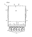
- FIG. 1 illustrates a telecommunications assembly 10 with mounting locations 12 for mounting a plurality of modules 14.
- Assembly 10 includes a chassis or housing 16 with a first major side 18, a second major side 20 and a pair of opposing transverse sides 22 extending between the first and second major sides.
- a mounting flange 24 may be mounted to each of the major sides extending generally oppositely of each other.
- a secondary or alternative mounting flange 26 may also be mounted to one of the major sides to provide options for mounting housing 16 to a particular size or shape of equipment rack, cabinet or other type of installation.
- Housing 16 defines a front opening 28 through which modules 14 are inserted within an interior 30 (shown below in FIG. 7 ) of housing 16. Openings 32 may be defined in the transverse sides 22 to permit access by a person into interior 30. Openings 32 may include a protective pad 34 about a perimeter to provide chafe and other injury to any hands which may pass into or out of interior 30 through one of the openings 32. Visible through opening 32 in FIG. 1 is a housing 40 of one of the modules 14 mounted within front opening 28. Flanges 24 and 26 may include a plurality of fastener openings 36 for mounting housing 16 where needed in a telecommunications installation.
- each module 14 includes a releasably catch 42 adjacent second major side 20. As can be seen below in and described with to FIG. 10 , catch 42 engages a portion of housing 16 to hold module 14 within front opening 28 and can also be deflected to permit withdrawal of module 14 from housing 16. Each module 14 also may include one or more cable exits 44 extending from a front face 46. Cable exits 44 permit telecommunications cables within module 14 to be directed outside of module 14, as will be described below with regard to FIG. 10 . As shown in FIG. 2 , front faces 46 of modules 14 are angled with regard to front opening 28, which may aid in the direction of cables exiting module 14 toward a desired location in the telecommunications installation. It is anticipated that front faces 46 could be made generally parallel to front edges 38 of transverse sides 22 at front opening 28 within the scope of the present disclosure.
- modules 14 includes unequal length flanges 48 and 50 which are received within correspondingly sized slots 52 and 54, respectively.
- Flange 48 and slot 52 are smaller in size than flange 50 and slot 54.
- Slot 52 is sized so that, while flange 48 may be received within slot 52, larger flange 50 will not fit. This ensures that modules 14 are positioned within front opening 28 in a particular desired orientation. Similar flanges are described in commonly-owned U.S. Patent No. 5,363,465 .
- Opposite latch 42 and mounted to housing 16 at each mounting location 12 are an adapter holder 56 releasably held within front opening 28 by a thumbscrew 58.
- Adapter holder 56 is described in further detail below with regard to FIGS. 9 to 16 .
- housing 16 further includes a back 60 opposite front opening 28, substantially closing off the rear of housing 16. Openings may be provided through back 60 to allow cables or air to pass, but it is anticipated that user access into interior 30 of housing 16 will be made through front opening 28.
- a lip or finger grip 62 may be included to aid removal of module 14 from housing 16. Finger grip 62 is preferably positioned on module 14 opposite latch 42 so that a user may apply opposing force with fingers or hands to securely grasp the module and remove it from housing 16.
- latch 42 of module 14 includes a recessed area 66 which engages an edge 64 of mounting location 12 to hold module 14 in place within front opening 28.
- Recessed area 66 is formed near a distal end of latch 42 and a flexible portion 68 extends from recessed area 66 to a point of connection to a first side 70 of module 14.
- Flexible portion 68 is resiliently deformable and allows a user to deflect latch 42 to disengage recessed area 66 from edge 64 and remove module 14 from housing 16 or for latch 42 to deflect as module 14 is inserted into front opening 28 and engage edge 64.
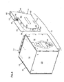
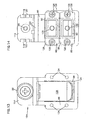
- Module 14 includes a second opposing side 72 and a back 78.
- An intermediate rear face 76 is formed in second side 72 by an inset side portion 74.
- a pair of fiber optic connectors 80 is positioned in rear face 76 to mate with fiber optic adapters mounted to adapter holder 56 within interior 30 of housing 16.
- Module housing 40 also includes a first transverse face 82 extending between first side 70, second side 72, back 78 and front face 46.
- a second transverse face 84 closes off the opposite side of module housing 40 between front face 46 and back 78 but extends beyond sides 70 and 72 to form flanges 48 and 50 (flange 50 is not visible in FIG. 7 ).
- flange 50 is visible as an extension of second transverse face 84 beyond side 70 of module 14.
- Module housing 40 may include curved transitions 86 between sides 70 and 72 and back 78. Transitions 86 may be shaped to provide bend radius protection to cables within interior 30 as the cables extend to adapters 88. Alternatively, sides 70 and 72 may terminate directly at back 78, depending on the needs for placing components within module housing 40 and efficiencies in manufacturing of module housing 40.
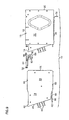
- FIG. 9 shows assembly 10 with adapter holder 54 exploded out from interior 30.
- Holder 54 includes an extension 86 to hold and position a pair of adapters 88 to engage connectors 80 of module 14.
- Each adapter 88 includes a first or rear end 90 and a second or front end 92, and each of the first and second ends are adapted to receive a fiber optic connector which may terminate a fiber optic cable.
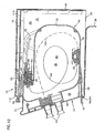
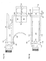
- FIG. 10 shows a cross-section of assembly 10 with a first cable 94 extending from connector 80 to an optical component 98, mounted within an interior 96 of module housing 40.
- Optical component 98 may be a splitter or a fan-out or another type of optically significant element.
- First cable 94 may be a multi-strand fiber cable with a plurality of strands of optical fiber and optical component 98 may be a fanout to separate the individual strands into each of a plurality of second cables 100.
- Second cables 100 extend from optical component 98 to cable exit 44.
- first cable 94 may be a single fiber whose signal is separated by optical component 98 which is a splitter and a plurality of second cables 100 carrying portions of the signal from first cable 94 may extend to cable exit 44.
- optical component 98 which is a splitter
- second cables 100 carrying portions of the signal from first cable 94 may extend to cable exit 44.
- the arrangement of optical fiber and sheathing at cable exit 44 may be as disclosed in commonly-owned U.S. Patent Application Serial No. 10/658,802 .
- An outside cable 102 may extend to rear end 90 of adapter 88 and be terminated by a connector 104.
- Connector 104 may be received in rear end 90 to be optically connected to connector 80 of module 14.
- Cable 102 may extend from interior 30 of housing 16 through an opening in one of sides 18, 20, or 22 in housing 16.
- assembly 10 has a module removed from one of the mounting locations 12 and includes an alternative adapter holder 154 in that mounting location 12.
- Holder 154 includes a shield 108 in front of second ends 92 of adapters 88.
- a housing 16 may be installed and a cable 102 led to and connected to first ends 90 of adapters 88, before a module 14 is placed in the associated mounting location 12. If cable 102 is illuminated and transmitting light signals, shield 108 will prevent accidental exposure to these signals which might damage eyes or other sensitive organs, or nearby communications equipment.
- holder 154 includes an opening 124 through extension 86 through which adapters 88 are mounted.
- Thumbscrew 56 extends through a front flange 114 and pair of wall engaging flanges 116 extend backward from adjacent front flange 114.
- other releasable features such as snap fit devices, quarter turn fasteners, swell latches or similar features may be used in place of thumbscrew 56 on holder 54 or 154.
- a slot 118 Positioned between a forward end of each flange 116 and front flange 114 is a slot 118.
- Toward a rear end of flanges 116 are a pair of wall slots 120. As shown in FIG.
- an inner wall 110 is positioned within interior 30 offset inwardly from first major surface 18.
- Wall slots 120 extend along both sides of inner wall 110.
- a turned-in forward edge 112 of first major surface 18 engages slot 118.
- extension 86 of holder 154 includes a plurality of fastener openings 124 for mounting adapters 88 to extension 86.
- Fasteners 126 may be extended through side flanges 128 of adapter 88 to permit secure mounting of adapters 88.
- Adapters 88 are shown as SC style connectors, although other types, styles and formats of adapters may be used within the scope of the present disclosure and connectors 80 and 104 changed to mate with these alternative adapters.
- an alignment device such as a split sleeve 130 to correctly position optical fiber terminated in a ferrule and held by connectors 80 and 104. Such alignment devices and termination ferrules are well known in the art.
- Shield 108 is curved when viewed from the side, as in FIG. 15 , so that shield 108 will be deflected by module 14 as module 14 is inserted into interior 30 through front opening 28 so that connectors 80 can mate with adapters 88.
- Shield 108 is preferably made of a resilient deformable material that will return to the position shown in FIG. 154 when the module 14 is withdrawn from mounting location 12.
- Shield 108 may be connected to central member 122 by a pair of fasteners such as screws 132.
- shield 108 could be connected to holder 154 by being formed integrally with holder 154 or by spot-welding or other fastening techniques.
- Insertion of module 14 into housing 16 at one of the mounting locations 12 may include first unfastening thumbscrew 56 and removing holder 54 or 154 from interior 30 through front opening 28.
- Cable 102 preferably includes enough excess length or slack within interior 30 to permit adapters 88 to be pulled through opening 28.
- connector 104 of cable 102 can be removed from first end 90 of adapter 88 to permit a polished endface of an optical fiber within cable 102 to be cleaned.
- Connector 104 can then be reinserted within first end 90.
- Holder 54 or 154 can be reinserted within interior 30 so that the holder engages inner wall 110 and inward turned extension 112 and thumbscrew 56 resecured.
- Insertion of module 14 into front opening 28 begins the mating of module 14 to housing 16 and adapters 88.
- Flanges 48 and 50 engage slots 52 and 54, respectively, as module 14 is inserted.
- Connectors 80 and portions of second side 72 engage and deflect shield 108 (if present) as connectors 80 approach second ends 92 of adapters 88. Further insertion of module 14 brings connectors 80 into and contact with adapters 88 and the connectors are received within second ends 92.
- Latch 42 is deflected inward as module 14 is inserted and then springs back so that recessed area 66 engages edge 64.
- Module 14 is now mounted within front opening 28 and interior 30 at mounting location 12 and in position to process and transmit signals from cable 102 through first cable 94, optical component 98 and second cable 100 within module interior 96.
Landscapes
- Physics & Mathematics (AREA)
- General Physics & Mathematics (AREA)
- Optics & Photonics (AREA)
- Engineering & Computer Science (AREA)
- Computer Networks & Wireless Communication (AREA)
- Electromagnetism (AREA)
- Signal Processing (AREA)
- Mechanical Coupling Of Light Guides (AREA)
- Light Guides In General And Applications Therefor (AREA)
- Optical Couplings Of Light Guides (AREA)
- Connector Housings Or Holding Contact Members (AREA)
- Input Circuits Of Receivers And Coupling Of Receivers And Audio Equipment (AREA)
Claims (12)
- Ensemble de télécommunications par fibre optique (10) comprenanta) un châssis (16) comprenant :un boîtier de châssis (16) ayant un premier côté principal (18), un second côté principal (20), et une paire de côtés transversaux opposés (22) s'étendant entre les côtés principaux (18, 20) définissant un intérieur (30) ayant une partie avant (28) et une partie arrière (60) opposée à la partie avant (28) ;une pluralité d'emplacements de montage (12) définis pour des modules de télécommunications (14) configurés pour être insérés dans le boîtier de châssis (16) à travers l'avant (28), les modules (14) étant de manière générale orientés parallèlement à l'un des côtés transversaux (22);chaque emplacement de montage (12) comprenant un module adaptateur (56), chaque module adaptateur (56) étant monté de manière amovible dans l'intérieur (30) du boîtier de châssis (16) et comprenant au moins un adaptateur de fibre optique (88), le au moins un adaptateur de fibre optique (88) du module adaptateur (56) étant configuré pour être apparié avec un module de télécommunications (14) pouvant être inséré dans le boîtier de châssis (16), chaque adaptateur de fibre optique (88) comprenant une extrémité avant (92) et une extrémité arrière (90), chaque extrémité étant configurée pour recevoir un connecteur de fibre optique complémentaire (80, 104) ;chaque module adaptateur (56) orientant le au moins un adaptateur de fibre optique (88) une extrémité avant (92) étant positionnée pour recevoir le connecteur de fibre optique complémentaire (80) inséré à travers l'avant (28) du boîtier de châssis (16) en direction de l'arrière (60) et de manière générale parallèlement aux côtés (22) ;chaque module adaptateur (56) étant positionné pour supporter le au moins un adaptateur (88) dans l'intérieur (30) du boîtier de châssis (16) de sorte qu'un câble de fibre optique (102) ayant un connecteur de fibre complémentaire (104) peut-être dirigé vers l'extrémité arrière (90) de l'adaptateur (88) et inséré dans celle-ci ;b) une pluralité de modules de télécommunications (14) insérés dans le boîtier de châssis (16), chaque module de télécommunications (14) comprenant :un boîtier de module (40) définissant un intérieur (96) et comprenant des première et seconde paires de côtés opposés (70, 72, 82, 84), une face avant (46), une face arrière (76) et un dos (78) espacé de la face avant (46)la face arrière (76) étant dirigée de manière générale vers le dos (78) du boîtier de module (16) ;la face arrière (76) définissant au moins un emplacement de support de connecteur supportant un connecteur de fibre optique (80) ayant un axe de connecteur longitudinal s'étendant parallèlement à un axe de modules'étendant entre la face avant (46) et le dos (78), une extrémité du connecteur (80) étant disposée à l'extérieur de l'intérieur (96) défini par le boîtier de module (40) ;la face arrière (76) étant positionnée à un emplacement entre la face avant (46) et le dos (78) dans un évidement (74) défini dans le boîtier de module (40) ;la face avant (46) comprenant un emplacement de sortie de câble (44) en communication avec l'intérieur (96) défini par le boîtier de module (40) ;le boîtier de module (40) comprenant une patte de verrouillage souple (42) s'étendant adjacente à la face avant (46), chaque module de télécommunications (14) étant monté dans le boîtier de châssis (16) de sorte que le connecteur (80) du module de télécommunications (14) vient en prise avec le au moins un adaptateur de fibre optique (88) du module adaptateur (56) monté sur le châssis (16), lorsque le module de télécommunications (14) est monté dans le boîtier de châssis (16).
- Ensemble de télécommunications selon la revendication 1,
caractérisé en ce que chaque emplacement de sortie de câble (44) comprend un prolongement extérieur en forme de cloche au-delà de la face avant (46). - Ensemble de télécommunications selon la revendication 2, caractérisé en ce que chaque module adaptateur (56) comprend :une cloison définissant :un support de dispositif de fixation (114) pour supporter un dispositif de fixation (56) s'étendant dans une première direction longitudinale ;un rebord longitudinal (116) s'étendant à partir du support de dispositif de fixation (114) dans une direction parallèle à la première direction longitudinale ;un corps principal (86) s'étendant à partir du rebord longitudinal (116), le corps principal (26) définissant des emplacements d'adaptateur (124) ; etdeux fentes (120) positionnées sur le rebord longitudinal (116) s'étendant dans une direction parallèle à la première direction longitudinale ; etune pluralité de composants d'appariement d'adaptateur (130) positionnés dans des emplacements d'adaptateur (104) du corps principal (86) de la cloison, chaque composant d'appariement d'adaptateur (130) étant configuré pour apparier deux connecteurs (80, 104) pour une transmission de signal par fibre optique entre les connecteurs (80, 104), chaque composant d'appariement d'adaptateur (130) alignant les deux connecteurs (80, 104) dans une direction parallèle à la première direction longitudinale.
- Ensemble de télécommunications selon la revendication 3, comprenant de plus un dispositif de fixation (56) dans le support de dispositif de fixation (114).
- Ensemble de télécommunications selon la revendication 3, caractérisé en ce que la pluralité de composants d'appariement d'adaptateur (130) sont alignés dans une direction transversale par rapport à la première direction longitudinale.
- Ensemble de télécommunications selon la revendication 3, caractérisé en ce qu'il comprend de plus un volet (108) positionné pour recouvrir les composants d'appariement d'adaptateur (130).
- Ensemble de télécommunications selon la revendication 1, caractérisé en ce que chaque module de télécommunications (14) comprend un diviseur de fibre (98) dans le boîtier de module (40).
- Procédé de montage d'un module de télécommunications (114) dans un boîtier (16) le procédé étant caractérisé par les étapes consistant à :fournir un boîtier (16) définissant un premier côté (18), un second côté (20) et au moins un côté transversal (22) s'étendant entre les premier et second côtés (10, 20), le boîtier (16) définissant un avant ouvert (28) et un arrière (60) opposé à l'avant ouvert (28), au moins un emplacement de montage (12) défini par le boîtier (16) pour recevoir le module de télécommunications (14) inséré à travers l'avant (28) du boîtier (16) ;agencer une pluralité d'adaptateurs de fibre optique (88) sur le boîtier (16), chaque adaptateur de fibre (88) comprenant une extrémité avant (92) et une extrémité arrière (90), chaque extrémité de l'adaptateur de fibre (88) étant configurée pour recevoir un connecteur de fibre complémentaire (80, 104), l'extrémité avant (92) étant positionnée pour recevoir un connecteur de fibre complémentaire (80) du module de télécommunications (14) inséré à travers l'avant (28) vers l'arrière (60) du boîtier (16), l'extrémité arrière (90) étant positionnée pour recevoir un connecteur de fibre complémentaire (104) et un câble de fibre optique (102) ;monter de manière amovible le module de télécommunications (14) sur le boîtier (16) à travers l'avant (28) vers l'arrière (60), de manière générale parallèlement au côté transversal (22) du boîtier (16), le module de télécommunications (14) comprenant au moins un connecteur de fibre (80) qui fait saillie à partir d'une face arrière (76) du module de télécommunications (14), le module de télécommunications (14) comprenant une patte de verrouillage souple (42) s'étendant adjacente à une face avant (46) du module de télécommunications (14), la patte de verrouillage souple (42) étant configurée pour former un verrouillage mutuel par encliquetage avec le boîtier (16) lorsque le module de télécommunications (14) est monté sur le boîtier (16) ;mettre en prise un adaptateur de fibre optique (88) du boîtier (16) avec le connecteur de fibre (80) du module de télécommunications (14) ; etfléchir la patte de verrouillage (42) du module de télécommunications (14) pour encliqueter le module de télécommunications (14) sur le boîtier (16).
- Procédé selon la revendication 8, caractérisé en ce que le module de télécommunications (14) comprend au moins un composant optique (98) dans l'intérieur (96) du boîtier de module (40), un premier câble de fibre optique (14) dans l'intérieur (96) s'étendant à partir du connecteur de fibre optique (80) de la face arrière (76) vers le composant optique (98) et au moins un second câble de fibre optique (100) s'étendant à partir du composant optique (98) vers un emplacement de sortie de câble (44) sur la face avant (46).
- Procédé selon la revendication 9, caractérisé en ce que le composant optique (98) est un diviseur optique, le premier câble de fibre optique (94) comprend un brin unique de fibre et une pluralité de seconds câbles de fibre optique (100) s'étend depuis le composant optique (98) vers l'emplacement de sortie de câble (44) sur la face avant (46).
- Procédé selon la revendication 8, caractérisé en ce que la patte de verrouillage souple (42) du module de télécommunications (14) comprend une zone en creux (66) qui vient en prise avec un bord (64) formé adjacent à l'avant (28) du boîtier (16) pour former le verrouillage mutuel par encliquetage entre le module de télécommunications (14) et le boîtier (16).
- Procédé selon la revendication 8, caractérisé en ce que chaque adaptateur de fibre optique (88) est monté sur un support (154) monté de manière amovible sur le boîtier (16).
Applications Claiming Priority (3)
| Application Number | Priority Date | Filing Date | Title |
|---|---|---|---|
| US10/980,978 US7376322B2 (en) | 2004-11-03 | 2004-11-03 | Fiber optic module and system including rear connectors |
| EP05826135A EP1808028B1 (fr) | 2004-11-03 | 2005-11-02 | Module et système de fibre optique comprenant des connecteurs arrières |
| EP08008856A EP1962519B1 (fr) | 2004-11-03 | 2005-11-02 | Module de fibre optique et système comportant des connecteurs arrières |
Related Parent Applications (2)
| Application Number | Title | Priority Date | Filing Date |
|---|---|---|---|
| EP05826135.5 Division | 2005-11-02 | ||
| EP08008856.0 Division | 2008-05-13 |
Publications (2)
| Publication Number | Publication Date |
|---|---|
| EP2249581A1 EP2249581A1 (fr) | 2010-11-10 |
| EP2249581B1 true EP2249581B1 (fr) | 2012-03-14 |
Family
ID=36143765
Family Applications (3)
| Application Number | Title | Priority Date | Filing Date |
|---|---|---|---|
| EP05826135A Active EP1808028B1 (fr) | 2004-11-03 | 2005-11-02 | Module et système de fibre optique comprenant des connecteurs arrières |
| EP10174170A Not-in-force EP2249581B1 (fr) | 2004-11-03 | 2005-11-02 | Système fibre optique comportant des connecteurs arrières |
| EP08008856A Active EP1962519B1 (fr) | 2004-11-03 | 2005-11-02 | Module de fibre optique et système comportant des connecteurs arrières |
Family Applications Before (1)
| Application Number | Title | Priority Date | Filing Date |
|---|---|---|---|
| EP05826135A Active EP1808028B1 (fr) | 2004-11-03 | 2005-11-02 | Module et système de fibre optique comprenant des connecteurs arrières |
Family Applications After (1)
| Application Number | Title | Priority Date | Filing Date |
|---|---|---|---|
| EP08008856A Active EP1962519B1 (fr) | 2004-11-03 | 2005-11-02 | Module de fibre optique et système comportant des connecteurs arrières |
Country Status (16)
| Country | Link |
|---|---|
| US (12) | US7376322B2 (fr) |
| EP (3) | EP1808028B1 (fr) |
| JP (1) | JP5006202B2 (fr) |
| KR (1) | KR101294571B1 (fr) |
| CN (1) | CN101095361B (fr) |
| AT (3) | ATE549867T1 (fr) |
| AU (1) | AU2005305007B2 (fr) |
| BR (1) | BRPI0517939B1 (fr) |
| DE (2) | DE602005023914D1 (fr) |
| DK (2) | DK1808028T3 (fr) |
| ES (2) | ES2302255T3 (fr) |
| HK (1) | HK1106911A1 (fr) |
| MX (1) | MX2007005310A (fr) |
| PL (2) | PL1962519T3 (fr) |
| TW (1) | TW200622337A (fr) |
| WO (1) | WO2006052675A2 (fr) |
Families Citing this family (125)
| Publication number | Priority date | Publication date | Assignee | Title |
|---|---|---|---|---|
| US5883995A (en) | 1997-05-20 | 1999-03-16 | Adc Telecommunications, Inc. | Fiber connector and adapter |
| US6885798B2 (en) | 2003-09-08 | 2005-04-26 | Adc Telecommunications, Inc. | Fiber optic cable and furcation module |
| US6920274B2 (en) * | 2003-12-23 | 2005-07-19 | Adc Telecommunications, Inc. | High density optical fiber distribution frame with modules |
| GB0402187D0 (en) | 2004-01-31 | 2004-03-03 | Tyco Electronics Raychem Nv | A crimp for an optical cable connector |
| US7376322B2 (en) | 2004-11-03 | 2008-05-20 | Adc Telecommunications, Inc. | Fiber optic module and system including rear connectors |
| US7194181B2 (en) * | 2005-03-31 | 2007-03-20 | Adc Telecommunications, Inc. | Adapter block including connector storage |
| US7400813B2 (en) * | 2005-05-25 | 2008-07-15 | Adc Telecommunications, Inc. | Fiber optic splitter module |
| US7260301B2 (en) * | 2005-05-25 | 2007-08-21 | Adc Telecommunications, Inc. | Outside plant fiber distribution enclosure with radial arrangement |
| US7330625B2 (en) * | 2005-05-25 | 2008-02-12 | Adc Telecommunications, Inc. | Underground enclosure mounting system |
| US7376323B2 (en) * | 2005-05-25 | 2008-05-20 | Adc Telecommunications, Inc. | Fiber optic adapter module |
| US7636507B2 (en) * | 2005-06-17 | 2009-12-22 | Adc Telecommunications, Inc. | Compact blind mateable optical splitter |
| US7416349B2 (en) * | 2005-07-27 | 2008-08-26 | Adc Telecommunications, Inc. | Fiber optic adapter module |
| US7346254B2 (en) * | 2005-08-29 | 2008-03-18 | Adc Telecommunications, Inc. | Fiber optic splitter module with connector access |
| US7623749B2 (en) * | 2005-08-30 | 2009-11-24 | Adc Telecommunications, Inc. | Fiber distribution hub with modular termination blocks |
| JP3987078B2 (ja) * | 2005-08-31 | 2007-10-03 | 日本電信電話株式会社 | 光コネクタ |
| US7330626B2 (en) * | 2005-08-31 | 2008-02-12 | Adc Telecommunications, Inc. | Cabinet including optical bulkhead plate for blown fiber system |
| US7190874B1 (en) | 2005-10-03 | 2007-03-13 | Adc Telecommunications, Inc. | Fiber demarcation box with cable management |
| US7245809B1 (en) * | 2005-12-28 | 2007-07-17 | Adc Telecommunications, Inc. | Splitter modules for fiber distribution hubs |
| US7720343B2 (en) | 2006-02-13 | 2010-05-18 | Adc Telecommunications, Inc. | Fiber distribution hub with swing frame and modular termination panels |
| US7418181B2 (en) | 2006-02-13 | 2008-08-26 | Adc Telecommunications, Inc. | Fiber optic splitter module |
| US7816602B2 (en) * | 2006-02-13 | 2010-10-19 | Adc Telecommunications, Inc. | Fiber distribution hub with outside accessible grounding terminals |
| US20080047502A1 (en) * | 2006-08-23 | 2008-02-28 | Michael Russo | Hybrid Cycle Electrolysis Power System with Hydrogen & Oxygen Energy Storage |
| US7711234B2 (en) * | 2006-10-02 | 2010-05-04 | Adc Telecommunications, Inc. | Reskinnable fiber distribution hub |
| US7474828B2 (en) | 2006-10-02 | 2009-01-06 | Emerson Network Power, Energy Systems, North America, Inc. | Slack limiting fiber management system for an optic fiber distribution hub |
| US20080080825A1 (en) * | 2006-10-02 | 2008-04-03 | Eduardo Leon | Optic fiber distribution hub |
| US7428363B2 (en) * | 2006-10-02 | 2008-09-23 | Emerson Network Power, Energy Systems, North America, Inc. | Distribution module for an optic fiber distribution hub |
| US7526174B2 (en) * | 2006-10-02 | 2009-04-28 | Emerson Network Power, Energy Systems, North America, Inc. | Universal splitter module holder for an optic fiber distribution hub |
| US7689089B2 (en) | 2006-10-11 | 2010-03-30 | Panduit Corp. | Release latch for pre-terminated cassette |
| US7583885B2 (en) * | 2006-11-28 | 2009-09-01 | Adc Telecommunications, Inc. | Fiber distribution enclosure |
| US7570860B2 (en) | 2007-01-19 | 2009-08-04 | Adc Telecommunications, Inc. | Adapter panel with lateral sliding adapter arrays |
| US7493002B2 (en) * | 2007-01-19 | 2009-02-17 | Adc Telecommunications, Inc. | Fiber optic adapter cassette and panel |
| US7570861B2 (en) | 2007-01-19 | 2009-08-04 | Adc Telecommunications, Inc. | Adapter panel with lateral sliding adapter arrays |
| US7522805B2 (en) * | 2007-03-09 | 2009-04-21 | Adc Telecommunications, Inc. | Wall mount distribution arrangement |
| US7391954B1 (en) | 2007-05-30 | 2008-06-24 | Corning Cable Systems Llc | Attenuated optical splitter module |
| US20080298743A1 (en) * | 2007-05-31 | 2008-12-04 | Konstantinos Saravanos | Microsplitter module for optical connectivity |
| US20080298748A1 (en) * | 2007-05-31 | 2008-12-04 | Terry Dean Cox | Direct-connect optical splitter module |
| US7590328B2 (en) * | 2007-08-02 | 2009-09-15 | Adc Telecommunications, Inc. | Fiber termination block with splitters |
| US8798427B2 (en) | 2007-09-05 | 2014-08-05 | Corning Cable Systems Llc | Fiber optic terminal assembly |
| US7536075B2 (en) | 2007-10-22 | 2009-05-19 | Adc Telecommunications, Inc. | Wavelength division multiplexing module |
| WO2009055446A1 (fr) * | 2007-10-22 | 2009-04-30 | Adc Telecommunications, Inc. | Répartiteur de distribution de fibre optique |
| US7885505B2 (en) | 2007-10-22 | 2011-02-08 | Adc Telecommunications, Inc. | Wavelength division multiplexing module |
| US7751672B2 (en) | 2007-10-31 | 2010-07-06 | Adc Telecommunications, Inc. | Low profile fiber distribution hub |
| US8229265B2 (en) | 2007-11-21 | 2012-07-24 | Adc Telecommunications, Inc. | Fiber distribution hub with multiple configurations |
| US8238709B2 (en) | 2007-12-18 | 2012-08-07 | Adc Telecommunications, Inc. | Multi-configuration mounting system for fiber distribution hub |
| US8107816B2 (en) | 2008-01-29 | 2012-01-31 | Adc Telecommunications, Inc. | Wavelength division multiplexing module |
| US7715682B2 (en) * | 2008-03-04 | 2010-05-11 | Adc Telecommunications, Inc. | Fiber distribution hub having an adjustable plate |
| EP2321681B1 (fr) | 2008-08-27 | 2015-10-28 | ADC Telecommunications, Inc. | Adaptateur pour fibre optique ayant une structure d'alignement de virole moulée en une seule pièce |
| US8452148B2 (en) | 2008-08-29 | 2013-05-28 | Corning Cable Systems Llc | Independently translatable modules and fiber optic equipment trays in fiber optic equipment |
| US11294135B2 (en) | 2008-08-29 | 2022-04-05 | Corning Optical Communications LLC | High density and bandwidth fiber optic apparatuses and related equipment and methods |
| AU2008362634A1 (en) | 2008-10-09 | 2010-04-15 | Corning Cable Systems (Shanghai) Co., Ltd | Fiber optic terminal having adapter panel supporting both input and output fibers from an optical splitter |
| US8879882B2 (en) | 2008-10-27 | 2014-11-04 | Corning Cable Systems Llc | Variably configurable and modular local convergence point |
| US8417074B2 (en) | 2008-11-21 | 2013-04-09 | Adc Telecommunications, Inc. | Fiber optic telecommunications module |
| US8428418B2 (en) * | 2008-12-09 | 2013-04-23 | Adc Telecommunications, Inc. | Fiber optic adapter plate and cassette |
| US8494329B2 (en) * | 2009-01-15 | 2013-07-23 | Adc Telecommunications, Inc. | Fiber optic module and chassis |
| EP2237091A1 (fr) | 2009-03-31 | 2010-10-06 | Corning Cable Systems LLC | Terminal à fibres optiques pouvant être assemblé de manière amovible |
| US7899300B2 (en) * | 2009-06-03 | 2011-03-01 | Emerson Network Power, Energy Systems, North America, Inc. | Dust caps for fiber optic connectors |
| US8244089B2 (en) | 2009-06-03 | 2012-08-14 | Emerson Network Power, Energy Systems, North America, Inc. | Dust caps for fiber optic connectors |
| WO2010148336A1 (fr) | 2009-06-19 | 2010-12-23 | Corning Cable Systems Llc | Appareils à fibres optiques à large bande et à densité élevée et équipement et procédés associés |
| ES2403007A1 (es) * | 2009-07-01 | 2013-05-13 | Adc Telecommunications, Inc | Concentrador de distribución de fibra para montaje en pared. |
| US8422846B2 (en) * | 2009-08-13 | 2013-04-16 | Commscope, Inc. Of North Carolina | Fiber management component |
| ES2398782T3 (es) * | 2009-09-03 | 2013-03-21 | Tyco Electronics Raychem Bvba | Conjunto conector de fibras ópticas y unidad de terminación de fibras |
| WO2011029022A2 (fr) * | 2009-09-04 | 2011-03-10 | Adc Telecommunications, Inc. | Terminal sur socle à châssis basculant |
| US8467651B2 (en) * | 2009-09-30 | 2013-06-18 | Ccs Technology Inc. | Fiber optic terminals configured to dispose a fiber optic connection panel(s) within an optical fiber perimeter and related methods |
| US8498510B2 (en) * | 2010-01-18 | 2013-07-30 | Adc Telecommunications, Inc. | Fiber distribution enclosure |
| CN102870021B (zh) | 2010-03-02 | 2015-03-11 | 蒂安电子服务有限责任公司 | 光纤通信模块 |
| US9547144B2 (en) | 2010-03-16 | 2017-01-17 | Corning Optical Communications LLC | Fiber optic distribution network for multiple dwelling units |
| US8792767B2 (en) | 2010-04-16 | 2014-07-29 | Ccs Technology, Inc. | Distribution device |
| EP2564250A4 (fr) | 2010-04-27 | 2013-11-13 | Adc Comm Shanghai Co Ltd | Module à fibres optiques et châssis |
| US11251608B2 (en) | 2010-07-13 | 2022-02-15 | Raycap S.A. | Overvoltage protection system for wireless communication systems |
| US9547145B2 (en) | 2010-10-19 | 2017-01-17 | Corning Optical Communications LLC | Local convergence point for multiple dwelling unit fiber optic distribution network |
| WO2013105998A2 (fr) | 2011-02-16 | 2013-07-18 | Tyco Electronics Corporation | Fermeture pour fibres optiques |
| US9182563B2 (en) | 2011-03-31 | 2015-11-10 | Adc Telecommunications, Inc. | Adapter plate for fiber optic module |
| WO2013033890A1 (fr) | 2011-09-06 | 2013-03-14 | Adc Telecommunications, Inc. | Adaptateur pour module de fibre optique |
| US9417418B2 (en) | 2011-09-12 | 2016-08-16 | Commscope Technologies Llc | Flexible lensed optical interconnect device for signal distribution |
| US8770861B2 (en) | 2011-09-27 | 2014-07-08 | Tyco Electronics Corporation | Outside plant termination enclosure |
| EP2764390B1 (fr) | 2011-10-07 | 2020-12-02 | CommScope Technologies LLC | Cassette de fibres optiques, système et procédé |
| US9219546B2 (en) | 2011-12-12 | 2015-12-22 | Corning Optical Communications LLC | Extremely high frequency (EHF) distributed antenna systems, and related components and methods |
| US9213157B2 (en) | 2012-01-06 | 2015-12-15 | Hewlett Packard Enterprise Development Lp | Connector modules to optically connect to electronic devices |
| US10110307B2 (en) | 2012-03-02 | 2018-10-23 | Corning Optical Communications LLC | Optical network units (ONUs) for high bandwidth connectivity, and related components and methods |
| US20130308915A1 (en) * | 2012-05-16 | 2013-11-21 | Scott Eaker Buff | Port tap fiber optic modules, and related systems and methods for monitoring optical networks |
| US9004778B2 (en) | 2012-06-29 | 2015-04-14 | Corning Cable Systems Llc | Indexable optical fiber connectors and optical fiber connector arrays |
| US9049500B2 (en) | 2012-08-31 | 2015-06-02 | Corning Cable Systems Llc | Fiber optic terminals, systems, and methods for network service management |
| US9146362B2 (en) | 2012-09-21 | 2015-09-29 | Adc Telecommunications, Inc. | Insertion and removal tool for a fiber optic ferrule alignment sleeve |
| US9146374B2 (en) | 2012-09-28 | 2015-09-29 | Adc Telecommunications, Inc. | Rapid deployment packaging for optical fiber |
| CN104838301B (zh) | 2012-09-28 | 2017-06-09 | 泰科电子英国有限公司 | 光纤盒 |
| US9223094B2 (en) | 2012-10-05 | 2015-12-29 | Tyco Electronics Nederland Bv | Flexible optical circuit, cassettes, and methods |
| US8909019B2 (en) | 2012-10-11 | 2014-12-09 | Ccs Technology, Inc. | System comprising a plurality of distribution devices and distribution device |
| EP2936228A1 (fr) | 2012-12-19 | 2015-10-28 | Tyco Electronics Raychem BVBA | Dispositif de distribution avec coupleurs ajoutés par incréments |
| US9128262B2 (en) * | 2013-02-05 | 2015-09-08 | Adc Telecommunications, Inc. | Slidable telecommunications tray with cable slack management |
| US9435975B2 (en) | 2013-03-15 | 2016-09-06 | Commscope Technologies Llc | Modular high density telecommunications frame and chassis system |
| WO2015040211A1 (fr) | 2013-09-23 | 2015-03-26 | Tyco Electronics Uk Ltd. | Châssis de télécommunications |
| WO2015126472A2 (fr) * | 2013-11-11 | 2015-08-27 | Adc Telecommunications, Inc. | Module de télécommunications |
| EP3100090A4 (fr) | 2014-01-28 | 2017-09-06 | ADC Telecommunications Inc. | Module de connexion de fibres optiques coulissant avec gestion de mou de câble |
| US9151920B2 (en) * | 2014-03-07 | 2015-10-06 | Go!Foton Holdings, Inc. | High density optics and electronics enclosure housing system with cable management |
| US9494758B2 (en) | 2014-04-03 | 2016-11-15 | Commscope Technologies Llc | Fiber optic distribution system |
| WO2015193384A2 (fr) | 2014-06-17 | 2015-12-23 | Tyco Electronics Raychem Bvba | Système de distribution de câble |
| WO2015200321A1 (fr) | 2014-06-23 | 2015-12-30 | Adc Telecommunications, Inc. | Ensemble et procédé de sortance de câble à fibres optiques |
| US10054753B2 (en) | 2014-10-27 | 2018-08-21 | Commscope Technologies Llc | Fiber optic cable with flexible conduit |
| AU2016263337A1 (en) | 2015-05-15 | 2018-01-04 | Adc Telecommunications (Shanghai) Distribution Co., Ltd. | Alignment sleeve assembly and optical fibre adapter |
| AU2015207954C1 (en) | 2015-07-31 | 2022-05-05 | Adc Communications (Australia) Pty Limited | Cable breakout assembly |
| US20170068693A1 (en) * | 2015-09-04 | 2017-03-09 | Microsoft Technology Licensing, Llc. | Exposing external content in an enterprise |
| US9971119B2 (en) * | 2015-11-03 | 2018-05-15 | Raycap Intellectual Property Ltd. | Modular fiber optic cable splitter |
| US10802237B2 (en) | 2015-11-03 | 2020-10-13 | Raycap S.A. | Fiber optic cable management system |
| US10606009B2 (en) | 2015-12-01 | 2020-03-31 | CommScope Connectivity Belgium BVBA | Cable distribution system with fan out devices |
| WO2017129815A1 (fr) | 2016-01-28 | 2017-08-03 | CommScope Connectivity Belgium BVBA | Enceinte hybride modulaire |
| US11131821B2 (en) | 2016-03-18 | 2021-09-28 | Commscope Technologies Llc | Optic fiber cable fanout conduit arrangements; components, and methods |
| US10222571B2 (en) | 2016-04-07 | 2019-03-05 | Commscope Technologies Llc | Telecommunications module and frame |
| EP3507633A4 (fr) | 2016-08-31 | 2020-04-01 | Commscope Technologies LLC | Dispositif de serrage et de serrage de câble à fibre optique |
| US10914909B2 (en) | 2016-10-13 | 2021-02-09 | Commscope Technologies Llc | Fiber optic breakout transition assembly incorporating epoxy plug and cable strain relief |
| DE102016125609A1 (de) | 2016-12-23 | 2018-06-28 | Gabo Systemtechnik Gmbh | Anschlusseinrichtung und Glasfaserverteilerkasten |
| WO2018136812A1 (fr) | 2017-01-20 | 2018-07-26 | Raycap S.A. | Système de transmission de puissance de systèmes de communication sans fil |
| EP3577504A2 (fr) | 2017-02-01 | 2019-12-11 | CommScope Connectivity Belgium BVBA | Borne de connexion scellée |
| WO2018208518A1 (fr) | 2017-05-08 | 2018-11-15 | Commscope Technologies Llc | Ensemble de transition de dérivation de fibres optiques |
| CN208297782U (zh) * | 2017-08-25 | 2018-12-28 | 光联通讯有限公司 | 光纤设备 |
| CN111164479B (zh) | 2017-10-02 | 2021-11-19 | 康普技术有限责任公司 | 光纤光学电路和制备方法 |
| US10416406B1 (en) | 2018-03-01 | 2019-09-17 | Afl Telecommunications Llc | Communications module housing |
| US10971928B2 (en) | 2018-08-28 | 2021-04-06 | Raycap Ip Assets Ltd | Integrated overvoltage protection and monitoring system |
| EP3845044B1 (fr) * | 2018-08-31 | 2023-02-15 | CommScope Connectivity Belgium BVBA | Ensembles bâtis d'éléments de distribution de fibre optique |
| US10451828B1 (en) | 2018-11-09 | 2019-10-22 | Afl Telecommunications Llc | Communications module housing |
| US11417992B2 (en) * | 2019-06-12 | 2022-08-16 | Ortronics, Inc. | Modular edge patching system |
| US11175470B2 (en) * | 2019-08-20 | 2021-11-16 | DMSI International | Enclosure assemblies for handling MDC connectors and associated cabling |
| US11369034B2 (en) | 2019-09-18 | 2022-06-21 | Ortronics, Inc. | Ejectable cassette, guide column, and ejectable cassette system |
| US11677164B2 (en) | 2019-09-25 | 2023-06-13 | Raycap Ip Assets Ltd | Hybrid antenna distribution unit |
| KR102189228B1 (ko) * | 2020-04-20 | 2020-12-09 | 주식회사 이스트포토닉스 | 슬롯형 광모듈 탈부착형 쉘프장치 |
| US11686912B1 (en) | 2020-08-06 | 2023-06-27 | DMSI International | Optical fiber assemblies for accommodating mini duplex connectors |
Family Cites Families (94)
| Publication number | Priority date | Publication date | Assignee | Title |
|---|---|---|---|---|
| US4650933A (en) * | 1985-07-15 | 1987-03-17 | At&T Bell Laboratories | Jack and test plug |
| US4820200A (en) * | 1987-02-13 | 1989-04-11 | Switchcraft, Inc. | Slab-like jack module |
| US4797114A (en) * | 1987-03-02 | 1989-01-10 | Switchcraft, Inc. | Jack circuit board assembly |
| US4770639A (en) * | 1987-03-02 | 1988-09-13 | Switchcraft, Inc. | Channelized jackfield |
| US4840568A (en) * | 1987-03-31 | 1989-06-20 | Adc Telecommunications, Inc. | Jack assembly |
| US4768961A (en) * | 1987-10-09 | 1988-09-06 | Switchcraft, Inc. | Jackfield with front removable jack modules having lamp assemblies |
| US5214673A (en) * | 1989-08-04 | 1993-05-25 | Adc Telecommunications, Inc. | Digital cross connect assembly |
| US5189410A (en) * | 1989-12-28 | 1993-02-23 | Fujitsu Limited | Digital cross connect system |
| US5199878A (en) * | 1990-11-15 | 1993-04-06 | Adc Telecommunications, Inc. | Plug-in jack card for normally closed contacts |
| DE4130706A1 (de) | 1991-09-14 | 1993-03-18 | Standard Elektrik Lorenz Ag | Stecker mit integriertem optischen koppler und verfahren zu dessen herstellung |
| WO1993020600A1 (fr) * | 1992-04-02 | 1993-10-14 | Adc Telecommunications, Inc. | Module de jack coaxial miniaturise |
| US5432875A (en) * | 1993-02-19 | 1995-07-11 | Adc Telecommunications, Inc. | Fiber optic monitor module |
| US5363465A (en) * | 1993-02-19 | 1994-11-08 | Adc Telecommunications, Inc. | Fiber optic connector module |
| US5363765A (en) * | 1993-03-12 | 1994-11-15 | Asahi Kasei Kogyo Kabushiki Kaisha | Electronic delay circuit for firing ignition element |
| US5317663A (en) * | 1993-05-20 | 1994-05-31 | Adc Telecommunications, Inc. | One-piece SC adapter |
| US5339379A (en) * | 1993-06-18 | 1994-08-16 | Telect, Inc. | Telecommunication fiber optic cable distribution apparatus |
| US5393249A (en) * | 1993-06-30 | 1995-02-28 | Adc Telecommunications, Inc. | Rear cross connect DSX system |
| TW232757B (en) * | 1994-01-21 | 1994-10-21 | Adc Telecommunications Inc | High-density fiber distribution frame |
| US5582525A (en) * | 1995-01-12 | 1996-12-10 | Adc Telecommunications, Inc. | Drop and insert card |
| US5600746A (en) | 1995-02-28 | 1997-02-04 | Lucent Technologies Inc. | Patch panel and collar for optical fiber couplers |
| US5627925A (en) * | 1995-04-07 | 1997-05-06 | Lucent Technologies Inc. | Non-blocking optical cross-connect structure for telecommunications network |
| US5613030A (en) * | 1995-05-15 | 1997-03-18 | The Whitaker Corporation | High density fiber optic interconnection enclosure |
| JPH09236712A (ja) * | 1996-02-28 | 1997-09-09 | Fujikura Ltd | 光分岐モジュール |
| JP3255836B2 (ja) * | 1996-02-28 | 2002-02-12 | 株式会社フジクラ | 光分岐モジュール |
| US5701380A (en) * | 1996-06-24 | 1997-12-23 | Telect, Inc. | Fiber optic module for high density supply of patching and splicing |
| US5685741A (en) * | 1996-06-27 | 1997-11-11 | Adc Telecommunications, Inc. | On demand plug-in jack card and monitor frame |
| US5793909A (en) | 1996-09-09 | 1998-08-11 | Lucent Technologies Inc. | Optical monitoring and test access module |
| US5694511A (en) * | 1996-09-09 | 1997-12-02 | Lucent Technologies Inc. | Optical switching apparatus and method for use in the construction mode testing of a modular fiber administration system |
| JP3659977B2 (ja) * | 1996-12-06 | 2005-06-15 | テルコーディア テクノロジーズ インコーポレイテッド | 存続可能な複数波長光通信ネットワーク用のリング間交差接続 |
| US5913701A (en) * | 1997-02-28 | 1999-06-22 | Adc Telecommunications, Inc. | DSX module with removable switching jack |
| JPH1164647A (ja) * | 1997-08-12 | 1999-03-05 | Nec Corp | 光パッケージ及び電子装置筺体 |
| US5946440A (en) * | 1997-11-17 | 1999-08-31 | Adc Telecommunications, Inc. | Optical fiber cable management device |
| US6208796B1 (en) * | 1998-07-21 | 2001-03-27 | Adc Telecommunications, Inc. | Fiber optic module |
| US6116961A (en) * | 1998-11-12 | 2000-09-12 | Adc Telecommunications, Inc. | Jack assembly |
| US6760531B1 (en) * | 1999-03-01 | 2004-07-06 | Adc Telecommunications, Inc. | Optical fiber distribution frame with outside plant enclosure |
| US6424781B1 (en) * | 1999-03-01 | 2002-07-23 | Adc Telecommunications, Inc. | Optical fiber distribution frame with pivoting connector panels |
| US6556763B1 (en) | 1999-03-01 | 2003-04-29 | Adc Telecommunications, Inc. | Optical fiber distribution frame with connector modules |
| US6535682B1 (en) * | 1999-03-01 | 2003-03-18 | Adc Telecommunications, Inc. | Optical fiber distribution frame with connector modules |
| US6370294B1 (en) * | 1999-06-25 | 2002-04-09 | Adc Telecommunications, Inc. | Fiber optic circuit and module with switch |
| WO2001009658A1 (fr) * | 1999-07-28 | 2001-02-08 | Pirelli Cavi E Sistemi S.P.A. | Cable optique sous-marin resistant a la propagation longitudinale de l'eau |
| US6485192B1 (en) | 1999-10-15 | 2002-11-26 | Tyco Electronics Corporation | Optical device having an integral array interface |
| US6263136B1 (en) | 1999-10-29 | 2001-07-17 | Lucent Technologies | Intelligent optical transmitter module |
| DE19956067A1 (de) * | 1999-11-22 | 2001-05-23 | Rxs Kabelgarnituren Gmbh & Co | Kassette zur Aufnahme von Lichtwellenleitern mit Überlängen und Lichtwellenleiter-Spleißverbindungen |
| US6371657B1 (en) | 1999-12-07 | 2002-04-16 | Molex Incorporated | Alignment system for mating connectors |
| US6363183B1 (en) * | 2000-01-04 | 2002-03-26 | Seungug Koh | Reconfigurable and scalable intergrated optic waveguide add/drop multiplexing element using micro-opto-electro-mechanical systems and methods of fabricating thereof |
| US6418262B1 (en) * | 2000-03-13 | 2002-07-09 | Adc Telecommunications, Inc. | Fiber distribution frame with fiber termination blocks |
| US7333606B1 (en) * | 2000-04-13 | 2008-02-19 | Adc Telecommunications, Inc. | Splitter architecture for a telecommunications system |
| US6668108B1 (en) * | 2000-06-02 | 2003-12-23 | Calient Networks, Inc. | Optical cross-connect switch with integrated optical signal tap |
| US6647197B1 (en) * | 2000-06-02 | 2003-11-11 | Panduit Corp. | Modular latch and guide rail arrangement for use in fiber optic cable management systems |
| CA2353140A1 (fr) | 2000-08-10 | 2002-02-10 | Fci America's Technology, Inc. | Adaptateur de connecteur optique |
| JP2002116350A (ja) * | 2000-10-05 | 2002-04-19 | Hirose Electric Co Ltd | 光ケーブル用アダプタ又はレセプタクル |
| US6523916B2 (en) * | 2000-12-22 | 2003-02-25 | Aurora Networks, Inc. | Chassis with repositionable plates |
| US6532332B2 (en) * | 2001-02-15 | 2003-03-11 | Adc Telecommunications, Inc. | Cable guide for fiber termination block |
| US6614953B2 (en) * | 2001-03-16 | 2003-09-02 | Photuris, Inc. | Modular all-optical cross-connect |
| US6461055B1 (en) * | 2001-04-11 | 2002-10-08 | Adc Telecommunications, Inc. | Fiber optic adapter with attenuator and method |
| US6533616B2 (en) * | 2001-04-13 | 2003-03-18 | Adc Telecommunications, Inc. | DSX jack including sliding rear connector |
| US6735361B2 (en) | 2001-06-01 | 2004-05-11 | Stratos Lightwave, Inc. | Modular wavelength division multiplexing (WDM) connector |
| US6824312B2 (en) * | 2001-06-04 | 2004-11-30 | Adc Telecommunications, Inc. | Telecommunications chassis and module |
| US6632106B2 (en) * | 2001-07-24 | 2003-10-14 | Adc Telecommunications, Inc. | Jack; jack assembly; and methods |
| US6616459B2 (en) * | 2001-08-24 | 2003-09-09 | Adc Telecommunications, Inc. | Card edge contact including compliant end |
| US6511330B1 (en) * | 2001-08-24 | 2003-01-28 | Adc Telecommunications, Inc. | Interconnect module |
| US6830465B2 (en) * | 2001-08-24 | 2004-12-14 | Adc Telecommunications, Inc. | Interconnect chassis and module |
| US6579014B2 (en) * | 2001-09-28 | 2003-06-17 | Corning Cable Systems Llc | Fiber optic receptacle |
| US6591051B2 (en) * | 2001-11-16 | 2003-07-08 | Adc Telecommunications, Inc. | Fiber termination block with angled slide |
| DE20201170U1 (de) | 2002-01-15 | 2002-05-29 | Infineon Technologies Ag | Vorrichtung zum Schutz der Steckeraufnahme eines opto-elektronischen Bauelements |
| US6688780B2 (en) * | 2002-02-07 | 2004-02-10 | Amphenol Corporation | Cantilevered shutter for optical adapter |
| US6554652B1 (en) * | 2002-02-15 | 2003-04-29 | Adc Telecommunications, Inc. | Jack assembly including baluns interface; and methods |
| US6863446B2 (en) * | 2002-03-05 | 2005-03-08 | Fci Americas Technology, Inc. | Optical connector adapter with latch inserts |
| US6850685B2 (en) * | 2002-03-27 | 2005-02-01 | Adc Telecommunications, Inc. | Termination panel with pivoting bulkhead and cable management |
| US6937807B2 (en) * | 2002-04-24 | 2005-08-30 | Adc Telecommunications, Inc. | Cable management panel with sliding drawer |
| DE10219892A1 (de) | 2002-05-03 | 2004-02-05 | Krone Gmbh | Kupplung für Glasfaserverbinder |
| JP4266319B2 (ja) * | 2002-09-06 | 2009-05-20 | 株式会社精工技研 | 光コネクタプラグ及び光コネクタ |
| US6804447B2 (en) * | 2002-11-05 | 2004-10-12 | Adc Telecommunications, Inc. | Fiber panel with integrated couplers |
| US6822874B1 (en) * | 2002-11-12 | 2004-11-23 | Wooshcom Corporation | Modular high availability electronic product architecture with flexible I/O |
| JP4105696B2 (ja) * | 2002-11-29 | 2008-06-25 | 富士通株式会社 | 電子装置に搭載されるユニット及び当該電子装置の伝送線路の接続機構 |
| US7142764B2 (en) * | 2003-03-20 | 2006-11-28 | Tyco Electronics Corporation | Optical fiber interconnect cabinets, termination modules and fiber connectivity management for the same |
| US7035519B2 (en) | 2003-05-02 | 2006-04-25 | Panduit Corp. | Fiber optic connector removal tool |
| US6832035B1 (en) * | 2003-05-30 | 2004-12-14 | Lucent Technologies Inc. | Optical fiber connection system |
| US7233731B2 (en) * | 2003-07-02 | 2007-06-19 | Adc Telecommunications, Inc. | Telecommunications connection cabinet |
| US6885798B2 (en) * | 2003-09-08 | 2005-04-26 | Adc Telecommunications, Inc. | Fiber optic cable and furcation module |
| US7303220B2 (en) * | 2003-09-29 | 2007-12-04 | Richco Inc. | Connector coupling/decoupling tool |
| US7453706B2 (en) * | 2003-11-13 | 2008-11-18 | Adc Telecommunications, Inc. | Module with interchangeable card |
| US7495931B2 (en) * | 2003-11-13 | 2009-02-24 | Adc Telecommunications, Inc. | Patch panel chassis |
| US6983095B2 (en) * | 2003-11-17 | 2006-01-03 | Fiber Optic Network Solutions Corporation | Systems and methods for managing optical fibers and components within an enclosure in an optical communications network |
| US20050232565A1 (en) * | 2004-04-16 | 2005-10-20 | Ross Heggestad | Normal through optical panel |
| US20050232551A1 (en) * | 2004-04-16 | 2005-10-20 | Cheng-Pei Chang | Devices for preventing lens contamination in optoelectronic modules and connectors |
| US7218827B2 (en) * | 2004-06-18 | 2007-05-15 | Adc Telecommunications, Inc. | Multi-position fiber optic connector holder and method |
| US7376322B2 (en) | 2004-11-03 | 2008-05-20 | Adc Telecommunications, Inc. | Fiber optic module and system including rear connectors |
| US20060239691A1 (en) * | 2005-04-20 | 2006-10-26 | Tellabs Operations, Inc. | Optical transceiver with connector |
| US7400813B2 (en) * | 2005-05-25 | 2008-07-15 | Adc Telecommunications, Inc. | Fiber optic splitter module |
| US7376323B2 (en) * | 2005-05-25 | 2008-05-20 | Adc Telecommunications, Inc. | Fiber optic adapter module |
| US7636507B2 (en) * | 2005-06-17 | 2009-12-22 | Adc Telecommunications, Inc. | Compact blind mateable optical splitter |
| US7346254B2 (en) * | 2005-08-29 | 2008-03-18 | Adc Telecommunications, Inc. | Fiber optic splitter module with connector access |
| US7245809B1 (en) * | 2005-12-28 | 2007-07-17 | Adc Telecommunications, Inc. | Splitter modules for fiber distribution hubs |
-
2004
- 2004-11-03 US US10/980,978 patent/US7376322B2/en active Active
-
2005
- 2005-11-02 BR BRPI0517939A patent/BRPI0517939B1/pt active IP Right Grant
- 2005-11-02 DK DK05826135T patent/DK1808028T3/da active
- 2005-11-02 JP JP2007540034A patent/JP5006202B2/ja not_active Expired - Fee Related
- 2005-11-02 AT AT10174170T patent/ATE549867T1/de active
- 2005-11-02 CN CN200580045479XA patent/CN101095361B/zh active Active
- 2005-11-02 AU AU2005305007A patent/AU2005305007B2/en active Active
- 2005-11-02 DE DE602005023914T patent/DE602005023914D1/de active Active
- 2005-11-02 MX MX2007005310A patent/MX2007005310A/es active IP Right Grant
- 2005-11-02 KR KR1020077012529A patent/KR101294571B1/ko not_active IP Right Cessation
- 2005-11-02 AT AT05826135T patent/ATE395790T1/de not_active IP Right Cessation
- 2005-11-02 ES ES05826135T patent/ES2302255T3/es active Active
- 2005-11-02 EP EP05826135A patent/EP1808028B1/fr active Active
- 2005-11-02 TW TW094138388A patent/TW200622337A/zh unknown
- 2005-11-02 DE DE602005006832T patent/DE602005006832D1/de active Active
- 2005-11-02 ES ES08008856T patent/ES2348764T3/es active Active
- 2005-11-02 DK DK08008856.0T patent/DK1962519T3/da active
- 2005-11-02 PL PL08008856T patent/PL1962519T3/pl unknown
- 2005-11-02 WO PCT/US2005/039827 patent/WO2006052675A2/fr active Application Filing
- 2005-11-02 EP EP10174170A patent/EP2249581B1/fr not_active Not-in-force
- 2005-11-02 AT AT08008856T patent/ATE483328T1/de not_active IP Right Cessation
- 2005-11-02 EP EP08008856A patent/EP1962519B1/fr active Active
- 2005-11-02 PL PL05826135T patent/PL1808028T3/pl unknown
-
2008
- 2008-01-14 HK HK08100456A patent/HK1106911A1/xx not_active IP Right Cessation
- 2008-04-29 US US12/150,757 patent/US7593614B2/en not_active Expired - Fee Related
-
2009
- 2009-09-17 US US12/561,676 patent/US8023791B2/en active Active
-
2011
- 2011-09-19 US US13/236,026 patent/US8331753B2/en active Active
-
2012
- 2012-12-10 US US13/709,402 patent/US8705928B2/en active Active
-
2014
- 2014-03-24 US US14/223,185 patent/US9213159B2/en not_active Expired - Fee Related
-
2015
- 2015-12-11 US US14/966,025 patent/US20160187604A1/en not_active Abandoned
-
2017
- 2017-02-01 US US15/422,157 patent/US9964726B2/en active Active
-
2018
- 2018-05-07 US US15/972,373 patent/US10359591B2/en not_active Expired - Fee Related
-
2019
- 2019-07-01 US US16/458,671 patent/US20200012064A1/en not_active Abandoned
-
2020
- 2020-09-08 US US17/014,100 patent/US11280974B2/en active Active
-
2022
- 2022-02-28 US US17/682,648 patent/US20220179162A1/en not_active Abandoned
Also Published As
Similar Documents
| Publication | Publication Date | Title |
|---|---|---|
| US11280974B2 (en) | Fiber optic module and system including rear connectors | |
| US8520997B2 (en) | Fiber optic splitter module | |
| US7376323B2 (en) | Fiber optic adapter module |
Legal Events
| Date | Code | Title | Description |
|---|---|---|---|
| PUAI | Public reference made under article 153(3) epc to a published international application that has entered the european phase |
Free format text: ORIGINAL CODE: 0009012 |
|
| AC | Divisional application: reference to earlier application |
Ref document number: 1808028 Country of ref document: EP Kind code of ref document: P Ref document number: 1962519 Country of ref document: EP Kind code of ref document: P |
|
| AK | Designated contracting states |
Kind code of ref document: A1 Designated state(s): AT BE BG CH CY CZ DE DK EE ES FI FR GB GR HU IE IS IT LI LT LU LV MC NL PL PT RO SE SI SK TR |
|
| 17P | Request for examination filed |
Effective date: 20110506 |
|
| GRAP | Despatch of communication of intention to grant a patent |
Free format text: ORIGINAL CODE: EPIDOSNIGR1 |
|
| GRAS | Grant fee paid |
Free format text: ORIGINAL CODE: EPIDOSNIGR3 |
|
| GRAA | (expected) grant |
Free format text: ORIGINAL CODE: 0009210 |
|
| AC | Divisional application: reference to earlier application |
Ref document number: 1962519 Country of ref document: EP Kind code of ref document: P Ref document number: 1808028 Country of ref document: EP Kind code of ref document: P |
|
| AK | Designated contracting states |
Kind code of ref document: B1 Designated state(s): AT BE BG CH CY CZ DE DK EE ES FI FR GB GR HU IE IS IT LI LT LU LV MC NL PL PT RO SE SI SK TR |
|
| REG | Reference to a national code |
Ref country code: GB Ref legal event code: FG4D |
|
| REG | Reference to a national code |
Ref country code: CH Ref legal event code: EP Ref country code: AT Ref legal event code: REF Ref document number: 549867 Country of ref document: AT Kind code of ref document: T Effective date: 20120315 |
|
| REG | Reference to a national code |
Ref country code: IE Ref legal event code: FG4D |
|
| REG | Reference to a national code |
Ref country code: DE Ref legal event code: R096 Ref document number: 602005033217 Country of ref document: DE Effective date: 20120516 |
|
| REG | Reference to a national code |
Ref country code: NL Ref legal event code: VDEP Effective date: 20120314 |
|
| PG25 | Lapsed in a contracting state [announced via postgrant information from national office to epo] |
Ref country code: LT Free format text: LAPSE BECAUSE OF FAILURE TO SUBMIT A TRANSLATION OF THE DESCRIPTION OR TO PAY THE FEE WITHIN THE PRESCRIBED TIME-LIMIT Effective date: 20120314 |
|
| LTIE | Lt: invalidation of european patent or patent extension |
Effective date: 20120314 |
|
| PG25 | Lapsed in a contracting state [announced via postgrant information from national office to epo] |
Ref country code: LV Free format text: LAPSE BECAUSE OF FAILURE TO SUBMIT A TRANSLATION OF THE DESCRIPTION OR TO PAY THE FEE WITHIN THE PRESCRIBED TIME-LIMIT Effective date: 20120314 Ref country code: GR Free format text: LAPSE BECAUSE OF FAILURE TO SUBMIT A TRANSLATION OF THE DESCRIPTION OR TO PAY THE FEE WITHIN THE PRESCRIBED TIME-LIMIT Effective date: 20120615 Ref country code: FI Free format text: LAPSE BECAUSE OF FAILURE TO SUBMIT A TRANSLATION OF THE DESCRIPTION OR TO PAY THE FEE WITHIN THE PRESCRIBED TIME-LIMIT Effective date: 20120314 |
|
| REG | Reference to a national code |
Ref country code: AT Ref legal event code: MK05 Ref document number: 549867 Country of ref document: AT Kind code of ref document: T Effective date: 20120314 |
|
| PG25 | Lapsed in a contracting state [announced via postgrant information from national office to epo] |
Ref country code: CY Free format text: LAPSE BECAUSE OF FAILURE TO SUBMIT A TRANSLATION OF THE DESCRIPTION OR TO PAY THE FEE WITHIN THE PRESCRIBED TIME-LIMIT Effective date: 20120314 |
|
| PG25 | Lapsed in a contracting state [announced via postgrant information from national office to epo] |
Ref country code: CZ Free format text: LAPSE BECAUSE OF FAILURE TO SUBMIT A TRANSLATION OF THE DESCRIPTION OR TO PAY THE FEE WITHIN THE PRESCRIBED TIME-LIMIT Effective date: 20120314 Ref country code: SI Free format text: LAPSE BECAUSE OF FAILURE TO SUBMIT A TRANSLATION OF THE DESCRIPTION OR TO PAY THE FEE WITHIN THE PRESCRIBED TIME-LIMIT Effective date: 20120314 Ref country code: PL Free format text: LAPSE BECAUSE OF FAILURE TO SUBMIT A TRANSLATION OF THE DESCRIPTION OR TO PAY THE FEE WITHIN THE PRESCRIBED TIME-LIMIT Effective date: 20120314 Ref country code: SE Free format text: LAPSE BECAUSE OF FAILURE TO SUBMIT A TRANSLATION OF THE DESCRIPTION OR TO PAY THE FEE WITHIN THE PRESCRIBED TIME-LIMIT Effective date: 20120314 Ref country code: BE Free format text: LAPSE BECAUSE OF FAILURE TO SUBMIT A TRANSLATION OF THE DESCRIPTION OR TO PAY THE FEE WITHIN THE PRESCRIBED TIME-LIMIT Effective date: 20120314 Ref country code: IS Free format text: LAPSE BECAUSE OF FAILURE TO SUBMIT A TRANSLATION OF THE DESCRIPTION OR TO PAY THE FEE WITHIN THE PRESCRIBED TIME-LIMIT Effective date: 20120714 Ref country code: EE Free format text: LAPSE BECAUSE OF FAILURE TO SUBMIT A TRANSLATION OF THE DESCRIPTION OR TO PAY THE FEE WITHIN THE PRESCRIBED TIME-LIMIT Effective date: 20120314 Ref country code: RO Free format text: LAPSE BECAUSE OF FAILURE TO SUBMIT A TRANSLATION OF THE DESCRIPTION OR TO PAY THE FEE WITHIN THE PRESCRIBED TIME-LIMIT Effective date: 20120314 |
|
| PG25 | Lapsed in a contracting state [announced via postgrant information from national office to epo] |
Ref country code: SK Free format text: LAPSE BECAUSE OF FAILURE TO SUBMIT A TRANSLATION OF THE DESCRIPTION OR TO PAY THE FEE WITHIN THE PRESCRIBED TIME-LIMIT Effective date: 20120314 Ref country code: PT Free format text: LAPSE BECAUSE OF FAILURE TO SUBMIT A TRANSLATION OF THE DESCRIPTION OR TO PAY THE FEE WITHIN THE PRESCRIBED TIME-LIMIT Effective date: 20120716 |
|
| PLBE | No opposition filed within time limit |
Free format text: ORIGINAL CODE: 0009261 |
|
| STAA | Information on the status of an ep patent application or granted ep patent |
Free format text: STATUS: NO OPPOSITION FILED WITHIN TIME LIMIT |
|
| PG25 | Lapsed in a contracting state [announced via postgrant information from national office to epo] |
Ref country code: AT Free format text: LAPSE BECAUSE OF FAILURE TO SUBMIT A TRANSLATION OF THE DESCRIPTION OR TO PAY THE FEE WITHIN THE PRESCRIBED TIME-LIMIT Effective date: 20120314 Ref country code: NL Free format text: LAPSE BECAUSE OF FAILURE TO SUBMIT A TRANSLATION OF THE DESCRIPTION OR TO PAY THE FEE WITHIN THE PRESCRIBED TIME-LIMIT Effective date: 20120314 Ref country code: DK Free format text: LAPSE BECAUSE OF FAILURE TO SUBMIT A TRANSLATION OF THE DESCRIPTION OR TO PAY THE FEE WITHIN THE PRESCRIBED TIME-LIMIT Effective date: 20120314 |
|
| 26N | No opposition filed |
Effective date: 20121217 |
|
| PG25 | Lapsed in a contracting state [announced via postgrant information from national office to epo] |
Ref country code: IT Free format text: LAPSE BECAUSE OF FAILURE TO SUBMIT A TRANSLATION OF THE DESCRIPTION OR TO PAY THE FEE WITHIN THE PRESCRIBED TIME-LIMIT Effective date: 20120314 |
|
| REG | Reference to a national code |
Ref country code: DE Ref legal event code: R097 Ref document number: 602005033217 Country of ref document: DE Effective date: 20121217 |
|
| PG25 | Lapsed in a contracting state [announced via postgrant information from national office to epo] |
Ref country code: ES Free format text: LAPSE BECAUSE OF FAILURE TO SUBMIT A TRANSLATION OF THE DESCRIPTION OR TO PAY THE FEE WITHIN THE PRESCRIBED TIME-LIMIT Effective date: 20120625 |
|
| REG | Reference to a national code |
Ref country code: CH Ref legal event code: PL |
|
| GBPC | Gb: european patent ceased through non-payment of renewal fee |
Effective date: 20121102 |
|
| PG25 | Lapsed in a contracting state [announced via postgrant information from national office to epo] |
Ref country code: CH Free format text: LAPSE BECAUSE OF NON-PAYMENT OF DUE FEES Effective date: 20121130 Ref country code: BG Free format text: LAPSE BECAUSE OF FAILURE TO SUBMIT A TRANSLATION OF THE DESCRIPTION OR TO PAY THE FEE WITHIN THE PRESCRIBED TIME-LIMIT Effective date: 20120614 Ref country code: LI Free format text: LAPSE BECAUSE OF NON-PAYMENT OF DUE FEES Effective date: 20121130 |
|
| REG | Reference to a national code |
Ref country code: IE Ref legal event code: MM4A |
|
| REG | Reference to a national code |
Ref country code: FR Ref legal event code: ST Effective date: 20130731 |
|
| REG | Reference to a national code |
Ref country code: DE Ref legal event code: R119 Ref document number: 602005033217 Country of ref document: DE Effective date: 20130601 |
|
| PG25 | Lapsed in a contracting state [announced via postgrant information from national office to epo] |
Ref country code: IE Free format text: LAPSE BECAUSE OF NON-PAYMENT OF DUE FEES Effective date: 20121102 Ref country code: DE Free format text: LAPSE BECAUSE OF NON-PAYMENT OF DUE FEES Effective date: 20130601 |
|
| PG25 | Lapsed in a contracting state [announced via postgrant information from national office to epo] |
Ref country code: FR Free format text: LAPSE BECAUSE OF NON-PAYMENT OF DUE FEES Effective date: 20121130 Ref country code: GB Free format text: LAPSE BECAUSE OF NON-PAYMENT OF DUE FEES Effective date: 20121102 |
|
| PG25 | Lapsed in a contracting state [announced via postgrant information from national office to epo] |
Ref country code: MC Free format text: LAPSE BECAUSE OF NON-PAYMENT OF DUE FEES Effective date: 20121130 Ref country code: TR Free format text: LAPSE BECAUSE OF FAILURE TO SUBMIT A TRANSLATION OF THE DESCRIPTION OR TO PAY THE FEE WITHIN THE PRESCRIBED TIME-LIMIT Effective date: 20120314 |
|
| PG25 | Lapsed in a contracting state [announced via postgrant information from national office to epo] |
Ref country code: LU Free format text: LAPSE BECAUSE OF NON-PAYMENT OF DUE FEES Effective date: 20121102 |
|
| PG25 | Lapsed in a contracting state [announced via postgrant information from national office to epo] |
Ref country code: HU Free format text: LAPSE BECAUSE OF FAILURE TO SUBMIT A TRANSLATION OF THE DESCRIPTION OR TO PAY THE FEE WITHIN THE PRESCRIBED TIME-LIMIT Effective date: 20051102 |