EP2249451A1 - Aufladevorrichtung und aufladeverfahren - Google Patents
Aufladevorrichtung und aufladeverfahren Download PDFInfo
- Publication number
- EP2249451A1 EP2249451A1 EP09715764A EP09715764A EP2249451A1 EP 2249451 A1 EP2249451 A1 EP 2249451A1 EP 09715764 A EP09715764 A EP 09715764A EP 09715764 A EP09715764 A EP 09715764A EP 2249451 A1 EP2249451 A1 EP 2249451A1
- Authority
- EP
- European Patent Office
- Prior art keywords
- charging
- amount
- cell
- discharge
- power
- Prior art date
- Legal status (The legal status is an assumption and is not a legal conclusion. Google has not performed a legal analysis and makes no representation as to the accuracy of the status listed.)
- Withdrawn
Links
Images


Classifications
-
- H—ELECTRICITY
- H02—GENERATION; CONVERSION OR DISTRIBUTION OF ELECTRIC POWER
- H02J—ELECTRIC POWER NETWORKS; CIRCUIT ARRANGEMENTS OR SYSTEMS FOR SUPPLYING OR DISTRIBUTING ELECTRIC POWER; SYSTEMS FOR STORING ELECTRIC ENERGY
- H02J7/00—Circuit arrangements for charging or discharging batteries or for supplying loads from batteries
- H02J7/60—Circuit arrangements for charging or discharging batteries or for supplying loads from batteries including safety or protection arrangements
- H02J7/61—Circuit arrangements for charging or discharging batteries or for supplying loads from batteries including safety or protection arrangements against overcharge
-
- H—ELECTRICITY
- H01—ELECTRIC ELEMENTS
- H01M—PROCESSES OR MEANS, e.g. BATTERIES, FOR THE DIRECT CONVERSION OF CHEMICAL ENERGY INTO ELECTRICAL ENERGY
- H01M10/00—Secondary cells; Manufacture thereof
- H01M10/42—Methods or arrangements for servicing or maintenance of secondary cells or secondary half-cells
- H01M10/44—Methods for charging or discharging
- H01M10/441—Methods for charging or discharging for several batteries or cells simultaneously or sequentially
-
- H—ELECTRICITY
- H01—ELECTRIC ELEMENTS
- H01M—PROCESSES OR MEANS, e.g. BATTERIES, FOR THE DIRECT CONVERSION OF CHEMICAL ENERGY INTO ELECTRICAL ENERGY
- H01M10/00—Secondary cells; Manufacture thereof
- H01M10/42—Methods or arrangements for servicing or maintenance of secondary cells or secondary half-cells
- H01M10/425—Structural combination with electronic components, e.g. electronic circuits integrated to the outside of the casing
-
- H—ELECTRICITY
- H01—ELECTRIC ELEMENTS
- H01M—PROCESSES OR MEANS, e.g. BATTERIES, FOR THE DIRECT CONVERSION OF CHEMICAL ENERGY INTO ELECTRICAL ENERGY
- H01M10/00—Secondary cells; Manufacture thereof
- H01M10/42—Methods or arrangements for servicing or maintenance of secondary cells or secondary half-cells
- H01M10/46—Accumulators structurally combined with charging apparatus
-
- H—ELECTRICITY
- H01—ELECTRIC ELEMENTS
- H01M—PROCESSES OR MEANS, e.g. BATTERIES, FOR THE DIRECT CONVERSION OF CHEMICAL ENERGY INTO ELECTRICAL ENERGY
- H01M10/00—Secondary cells; Manufacture thereof
- H01M10/42—Methods or arrangements for servicing or maintenance of secondary cells or secondary half-cells
- H01M10/48—Accumulators combined with arrangements for measuring, testing or indicating the condition of cells, e.g. the level or density of the electrolyte
- H01M10/482—Accumulators combined with arrangements for measuring, testing or indicating the condition of cells, e.g. the level or density of the electrolyte for several batteries or cells simultaneously or sequentially
-
- H—ELECTRICITY
- H02—GENERATION; CONVERSION OR DISTRIBUTION OF ELECTRIC POWER
- H02J—ELECTRIC POWER NETWORKS; CIRCUIT ARRANGEMENTS OR SYSTEMS FOR SUPPLYING OR DISTRIBUTING ELECTRIC POWER; SYSTEMS FOR STORING ELECTRIC ENERGY
- H02J7/00—Circuit arrangements for charging or discharging batteries or for supplying loads from batteries
- H02J7/50—Circuit arrangements for charging or discharging batteries or for supplying loads from batteries acting upon multiple batteries simultaneously or sequentially
- H02J7/52—Circuit arrangements for charging or discharging batteries or for supplying loads from batteries acting upon multiple batteries simultaneously or sequentially for charge balancing, e.g. equalisation of charge between batteries
- H02J7/54—Passive balancing, e.g. using resistors or parallel MOSFETs
-
- H—ELECTRICITY
- H02—GENERATION; CONVERSION OR DISTRIBUTION OF ELECTRIC POWER
- H02J—ELECTRIC POWER NETWORKS; CIRCUIT ARRANGEMENTS OR SYSTEMS FOR SUPPLYING OR DISTRIBUTING ELECTRIC POWER; SYSTEMS FOR STORING ELECTRIC ENERGY
- H02J7/00—Circuit arrangements for charging or discharging batteries or for supplying loads from batteries
- H02J7/90—Regulation of charging or discharging current or voltage
- H02J7/933—Regulation of charging or discharging current or voltage the cycle being controlled or terminated in response to electric parameters
-
- H—ELECTRICITY
- H02—GENERATION; CONVERSION OR DISTRIBUTION OF ELECTRIC POWER
- H02J—ELECTRIC POWER NETWORKS; CIRCUIT ARRANGEMENTS OR SYSTEMS FOR SUPPLYING OR DISTRIBUTING ELECTRIC POWER; SYSTEMS FOR STORING ELECTRIC ENERGY
- H02J7/00—Circuit arrangements for charging or discharging batteries or for supplying loads from batteries
- H02J7/90—Regulation of charging or discharging current or voltage
- H02J7/971—Regulation of charging or discharging current or voltage the charge cycle being controlled or terminated in response to non-electric parameters
- H02J7/973—Regulation of charging or discharging current or voltage the charge cycle being controlled or terminated in response to non-electric parameters in response to degree of gas development in the battery
-
- Y—GENERAL TAGGING OF NEW TECHNOLOGICAL DEVELOPMENTS; GENERAL TAGGING OF CROSS-SECTIONAL TECHNOLOGIES SPANNING OVER SEVERAL SECTIONS OF THE IPC; TECHNICAL SUBJECTS COVERED BY FORMER USPC CROSS-REFERENCE ART COLLECTIONS [XRACs] AND DIGESTS
- Y02—TECHNOLOGIES OR APPLICATIONS FOR MITIGATION OR ADAPTATION AGAINST CLIMATE CHANGE
- Y02E—REDUCTION OF GREENHOUSE GAS [GHG] EMISSIONS, RELATED TO ENERGY GENERATION, TRANSMISSION OR DISTRIBUTION
- Y02E60/00—Enabling technologies; Technologies with a potential or indirect contribution to GHG emissions mitigation
- Y02E60/10—Energy storage using batteries
Definitions
- the present invention relates to a charging apparatus and a charging method and particularly to a technique for charging secondary cells in just proportion.
- a so-called multistage constant current charging method which reduces influence of internal resistance of a secondary cell and enables charging up to a state closer to full charge by charging the secondary cell with a specified constant current until a voltage thereof reaches a specified voltage and, thereafter, charging it with a current having a smaller value (for example, see Patent Document 1).
- a charging apparatus normally stops charging, assuming that full charge is reached such as when a cell voltage of a secondary cell reaches a specified value, when a charging current reaches a specified current value and when a specified time elapsed after the voltage of the secondary cell reached a specified voltage.
- the present invention has been implemented in view of the above situation and an object thereof is to provide a charging apparatus and a charging method capable of reliably preventing overcharge by carrying out charging in just proportion.
- the present invention is directed to a charging apparatus for charging a secondary cell by supplying a charging current thereto, comprising a discharge amount detection means for detecting an amount of power discharged from the secondary cell in a non-charging state; a charge amount detection means for detecting an amount of power charged into the secondary cell in a charging state; and a charging control means for stopping charging when the amount of charged power becomes equal to the amount of discharged power during a charging period.
- the present invention is directed to a charging apparatus for charging a cell group, in which a plurality of secondary cells are connected in series, by supplying a charging current to the cell group, comprising an overcharge protection circuit including discharge route circuits provided to each of the secondary cells and adapted to cause the secondary cells being charged to discharge by connecting the secondary cells to the discharge route circuits based on cell voltages of the secondary cells or to stop discharging by cutting off the secondary cells from the discharge route circuits; and a charging control means for continuing charging while reducing the charging current until the discharge of the secondary cell having started discharging to the discharge route circuit is stopped when the discharge of any one of the secondary cells to the discharge route circuit is started, wherein the charging control means stops charging when an amount of power charged into the cell group becomes equal to an amount of power discharged from the cell group in a non-charging state.
- the present invention is directed to a charging apparatus for charging a cell group, in which a plurality of secondary cells are connected in series, by supplying a charging current to the cell group, comprising a gas generation detection means for detecting gas generation from any one of the secondary cells while the cell group is being charged; and a charging control means for continuing charging while reducing the charging current until the gas generation is stopped when the gas generation is detected, wherein the charging control means stops charging when an amount of power charged into the cell group becomes equal to an amount of power discharged from the cell group in a non-charging state.
- any one of the above charging apparatuses of the present invention further comprises an output means for outputting a measure of replacement time of the secondary cell based on a count value of the number of times the secondary cell is charged and a total number of possible charging which specifies the life of the secondary cell.
- the present invention is directed to a charging method for charging a secondary cell by supplying a charging current thereto, comprising the steps of detecting an amount of power discharged from the secondary cell in a non-charging state; and stopping charging when an amount of power charged into the secondary cell becomes equal to the amount of discharged power during a charging period.
- charging since charging is stopped when the amount of charged power and the amount of discharged power becomes equal during the charging period, charging can be carried out in just proportion and, particularly, overcharge can be reliably prevented since there is no likelihood of charging beyond a discharge amount.
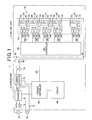
- FIG. 1 is a diagram showing the construction of a charging apparatus 1 according to this embodiment.
- the charging apparatus 1 is provided with a battery unit 2 for storing power and a charger unit 4 for charging the battery unit 2 by supplying power thereto.
- the charger unit 4 includes an external power connector 6, a charger 8, a charger controller 10, a current detector 12, a display 14 and a cut-off switch 16.
- the external power connector 6 is a connector connected to an external power supply 18 such as a commercial power supply, and power of the external power supply 18 is input to the charger 8.
- the charger 8 charges the battery unit 2 and drives an external load 19 by supplying the power of the external power supply 18 to the battery unit 2 and the external load 19.
- This external load 19 is a device which receives the supply of stored power of the battery unit 2 during the power stoppage of the external power supply 18. More specifically, the battery unit 2 and the external load 19 are connected in parallel to the charger 8, and a parallel circuit 9 is formed by these battery unit 2 and external load 19.
- the charger 8 supplies a DC charging current Ic to the battery unit 2 and supplies power to the external load 19 by applying a voltage ⁇ to this parallel circuit 9.
- the charger 8 enters a high-impedance state when viewed from the parallel circuit 9 composed of the battery unit 2 and the external load 19, wherefore the battery unit 2 and the external load 19 are automatically connected in series and stored power is supplied from the battery unit 2 to the external load 19.
- the charger controller 10 variably controls a current value of the charging current Ic during charging and is connected to the battery unit 2 via a signal line 20.
- the charger controller 10 controls the charging current Ic based on a signal received from the battery unit 2 via this signal line 20.
- the current detector 12 is disposed in a series circuit connecting the charger 8 and the battery unit 2, detects the charging current Ic flowing from the battery unit 2 toward the charger 8 and a discharging current Id flowing from the charger 8 according to discharge and outputs to the charger controller 10.
- the charger controller 10 variably controls the current value of the charging current Ic based on a detection signal of the current detector 12.
- the charger controller 10 includes a charge amount detector 60 for taking and sampling the detection signal of the current detector 12 at intervals of a preset time and adding the sampled charging currents Ic to calculate and detect a charge amount Wc during charging periods, a discharge amount detector 62 for adding the sampled discharging currents Id to calculate and detect a discharge amount Wd during discharging periods, and a storage 64 for storing a charge number counted every time charging is carried out. This storage 64 further stores a maximum charge number to be described later which is a total number of possible charging and specifies the life of the cell group 24.
- the display 14 displays various pieces of information, for example, a calculated value of the present storage amount W of the battery unit 2 and the ratio of the present charge number to the maximum charge number under the control of the charger controller 10. By the display of this ratio, how far the life of the cell group 24 has been consumed up to the present can be grasped and time for replacement can be estimated.
- the cut-off switch 16 is a constantly closed switch for stopping the discharge of the battery unit 2, disposed in the series circuit connecting the charger 8 and the battery unit 2, and opened to prevent overdischarge of the battery unit 2 when the battery unit 2 supplies power to the external load 19 under the control of the charger controller 10. In this way, discharge accompanying power supply from the battery unit 2 to the external load 19 or the like is stopped to prevent overdischarge.
- the cut-off switch 16 is the constantly closed switch, an electrically conductive state is normally maintained in between the battery unit 2 and the external load 19. Since the electrically conductive state is constantly kept in between the battery unit 2 and the external load 19 without being cut off by a switch or the like, even if the power stoppage of the external power supply 18 occurs, a situation is prevented in which this switch is not activated due to stopped power supply and the battery unit 2 and the external load 19 are left cut off. However, if the electrically conductive state is constantly maintained in between the battery unit 2 and the external load 19, the stored power of the battery unit 2 is supplied to the external load 19 while the battery unit 2 is not being charged.
- the charging apparatus 1 prevents power from being supplied from the battery unit 2 to the external load 19 and unnecessarily discharged by carrying out zero current charging for maintaining the charging current Ic flowing into the battery unit 2 substantially at zero during non-charging periods.
- the charger controller 10 feedback controls the voltage ⁇ applied to the parallel circuit 9 based on a detection value of the current detector 12 so that the charging current Ic flowing into the battery unit 2 is maintained substantially at zero.
- the voltage ⁇ and the voltage of the battery unit 2 become substantially equal to substantially zero a voltage difference, the charging current Ic to the battery unit 2 becomes substantially zero, and this state is held to hold the supply of the stored power from the battery unit 2 to the external load 19 in a stopped state.
- the battery unit 2 includes the cell group 24 composed of n (n ⁇ 2) secondary cells 22 connected in series, and an overcharge protection circuit (balancing circuit) 26.
- the secondary cells 22 are, for example, lithium polymer cells as an example of lithium ion cells. Besides, it is possible to use arbitrary secondary cells such as nickel hydrogen cells and nickel cadmium cells. However, all the secondary cells 22 constituting the cell group 24 are secondary cells of the same type.
- the battery unit 2 includes an anode terminal 30 electrically connected to an anode of the cell group 24 and a cathode terminal 32 electrically connected to a cathode of the cell group 24, and these anode terminal 30 and cathode terminal 32 are electrically connected to the charger unit 4. During charging periods, the charging current Ic is supplied from the charger unit 4 to the cell group 24 via the anode terminal 30 to charge the cell group 24.
- the overcharge protection circuit 26 protects overcharge of the secondary cells 22 by aligning voltage balances among the secondary cells 22 and includes discharge route circuits 34 provided in parallel to the respective secondary cells 22, detector groups 36 provided to the respective secondary cells 22 and a cell controller 38.
- Each discharge route circuit 34 is a circuit connecting a discharge resistor (balancing resistor) 40 and a switching element 42 in series in its path.
- the switching element 42 is a constantly open contact and closed when a cell voltage Vb of the secondary cell 22 reaches an overcharge protection voltage Vth1.
- This overcharge protection voltage Vth1 is set to be lower than a full charge voltage Vm according to the type of the secondary cell 22 and does not exceed 4.2 V at which a fully charged state is, for example, assumed in the case of a lithium polymer cell.
- the discharge route circuit 34 is electrically connected to the secondary cell 22 that starts discharging to the discharge route circuit 34.
- the cell voltage Vb of the secondary cell 22 gradually decreases due to energy release by discharge, a reduction in flowing amount of the charging current Ic into the secondary cell 22 because of bypass of the charging current Ic to the discharge route circuit 34 or the like.
- the switching element 42 is opened to stop discharge to the discharge route circuit 34. During charging periods, transition is made to a charging state again.
- a difference between the overcharge protection voltage Vth1 and the protection end voltage Vth2 is set at such a value as to be able to prevent at least chattering of the switching element 42.
- the charging current Ic flowing into this secondary cell 22 is bypassed to the discharge route circuit 34 to be introduced to the secondary cell 22 at a later stage.
- a value of the bypassed current is determined by a resistance value of the discharge resistor 40.
- a detector group 36 includes an overcharge protection detector 44, an upper limit voltage detector 46 and a discharge cut-off detector 48. These overcharge protection detector 44, upper limit voltage detector 46 and discharge cut-off detector 48 form a comparator circuit comparing the cell voltage Vb of the secondary cell 22 with a specified voltage set for each secondary cell 22.
- the overcharge protection detector 44 detects the cell voltage Vb of the secondary cell 22, compares this cell voltage Vb and the above overcharge protection voltage Vth1 and causes the secondary cell 22 to discharge to the discharge route circuit 34 by closing the switching element 42 when the cell voltage Vb exceeds the overcharge protection voltage Vth1.
- the overcharge protection detector 44 also stops discharge of the secondary cell 22 to the discharge route circuit 34 by opening the switching element 42 when the cell voltage Vb falls below the protection end voltage Vth2.
- the overcharge protection detector 44 outputs to the cell controller 38 an open/close signal indicating a closed/closed state of the switching element 42, i.e. start/stop of discharge every time the switching element 42 is opened or closed.
- the cell controller 38 Upon receiving such an open/close signal, the cell controller 38 outputs the open/close signal to the charger controller 10 of the charger unit 4 via the signal line 20, whereby the charger controller 10 can detect the presence or absence of discharge to the discharge route circuit 34.
- the charger controller 10 performs such a control as to reduce the charging current Ic until discharge to the discharge route circuit 34 is stopped when detecting based on the open/close signal during a charging period that any one of the secondary cells 22 starts discharge to the discharge route circuit 34. Such a control is described later.
- the upper limit voltage detector 46 detects the cell voltage Vb of the secondary cell 22 and outputs a detection signal to the cell controller 38 when the cell voltage Vb of the secondary cell 22 reaches an upper limit voltage Vth3 as an upper limit value of permissible voltages.
- the cell controller 38 outputs such a detection signal to the charger controller 10 via the signal line 20.
- the charger controller 10 quickly stops charging of the battery unit 2 when detecting based on the detection signal from the upper limit voltage detector 46 that the cell voltage Vb of any one of the secondary cells 22 reached the upper limit value of permissible voltages.
- the discharge cut-off detector 48 detects the cell voltage Vb of the secondary cell 22 and compares this cell voltage Vb and a discharge cut-off voltage Vth4 while the cell group 24 is not being charged, i.e. while the power of the cell group 24 is supplied to the external load 19, and outputs a detection signal to the cell controller 38 when the cell voltage Vb falls below the discharge cut-off voltage Vth4.
- the discharge cut-off voltage Vth4 is designed to prevent the secondary cell 22 from entering a state where the secondary cell 22 discharges beyond an end voltage, i. e. an overdischarge state and set at a voltage above the end voltage. For example, if the secondary cell 22 is a lithium polymer cell, the discharge cut-off voltage Vth4 is set at about 3 V.
- the cell controller 38 outputs a cut-off signal, which indicates that discharge should be cut off, to the charger controller 10 via the signal line 20 when receiving the detection signal from any one of the discharge cut-off detectors 48.
- the charger controller 10 opens the cut-off switch 16 when receiving the cut-off signal from the cell controller 38. In this way, discharge caused by power supply from the battery unit 2 to the external load 19 or the like is stopped.
- this charging apparatus 1 includes a temperature detection sensor such as a thermistor for detecting a cell temperature of the cell group 24 and stops charging when the temperature of the cell group 24 exceeds a specified temperature (e.g. 60°C in lithium polymer cells) during charging periods.
- FIG. 2 is a flow chart showing a charging process of the charging apparatus 1
- FIG. 3 is a chart showing charging patterns by the charging apparatus 1. Note that FIG. 3 shows charging patterns of two secondary cells 22A, 22B having different cell voltage rising characteristics during charging periods.
- the charging apparatus 1 monitors the discharge amount Wd during non-charging periods by continuously detecting the discharge amount Wd by the discharge amount detector 62 (Step S1).
- Step S2 When charging start conditions are satisfied (Step S2: YES), when charging start conditions are satisfied (Step S1: YES), after the charge number is counted up to be updated (Step S3), the charging current Ic having a current value Iini is supplied to the battery unit 2 to start charging (Step S4). Then, the charging apparatus 1 monitors the charge amount Wc by continuously detecting the charge amount Wc by the charge amount detector 60 during charging periods (Step S5).
- Various conditions for example, a condition that the cell group 24 is no longer in the fully charged state, a condition that the cut-off switch 16 is opened to prevent overcharge and a condition that a specified period has elapsed after the completion of the previous charging are set as the charging start conditions.
- the charging apparatus 1 Upon starting the supply of the charging current Ic having the current value Iini, the charging apparatus 1 adjusts the voltage ⁇ applied to the cell group 24 so that the current value of the charging current Ic becomes the current value Iini while sampling the detection signal by the current detector 12. As a result, as shown in FIG. 3 , when the supply of the charging current Ic is started to start charging (time t0), the cell voltages Vb of the respective secondary cells 22A, 22B of the cell group 24 start rising from charge initial voltages V0a, V0b.
- the overcharge protection detector 44 of the secondary cell 22A closes the switching element 42 to prevent the secondary cell 22A from being overcharged, thereby connecting the secondary cell 22A to the discharge route circuit 34 to start discharge.
- an open/close signal is output to the charge controller 10 and discharge of the secondary cell 22A to the discharge route circuit 34 is detected by the charge controller 10.
- Step S6 when detecting discharge of any one of the secondary cells 22 to the discharge route circuit 34 (Step S6: YES), the charge controller 10 successively reduces the current value of the charging current Ic (Step S7). In this way, as shown in FIG. 3 , the current value of the charging current Ic is reduced from time t1 when the cell voltage Vb of the secondary cell 22A reaches the overcharge protection voltage Vth1.
- the cell voltage Vb of the secondary cell 22A is gradually reduced according to discharge to the discharge route circuit 34 and a decrease of the charging current Ic and, when the cell voltage Vb falls to the protection end voltage Vth2 (time t2), the overcharge protection detector 44 of the secondary cell 22A opens the switching element 42 to stop discharge of the secondary cell 22A to the discharge route circuit 34.
- This stop of the discharge to the discharge route circuit 34 is detected by the charge controller 10 by the output of the open/close signal to the charge controller 10.
- Step S8 when detecting the stop of the discharge of the secondary cell 22 to the discharge route circuit 34 (Step S8: YES), the charge controller 10 stops reducing the current value of the charging current Ic and fixes the current value at a present value (Step S9) and continues charging by returning a process procedure to Step S6.
- the charging current Ic is fixed at a current value reached when the charging current Ic decreases until the cell voltage Vb of the secondary cell 22A falls to the protection stop voltage Vth2 to stop the discharge. Note that not only the cell voltage Vb of the secondary cell 22A, but also that of the other secondary cell 22B are reduced as the charging current Ic is reduced.
- a process of reducing the charging current Ic until the discharge of the secondary cell 22 to the discharge route circuit 34 is stopped is repeatedly performed every time the discharge of any one of the secondary cells 22 to the discharge route circuit 34 is detected.
- This repeat count changes according to a difference in the voltage rising characteristic during the charging, a degree of deterioration and the like of the secondary cells 22, and the process is not constantly repeated by a fixed number of times.
- the charging current Ic decreases and falls below a lower limit charging current value Ith (time t3) when being reduced by the process of the above Step S4 as shown in FIG. 3 .
- This lower limit charging current value Ith is set at a specified current value, which the respective secondary cells 22 indicate when approaching the fully charged state.
- Step S10 when detecting that the charging current Ic fell to or below a lower limit charging current value Ith (Step S10: YES), the charge controller 10 continues charging while maintaining the charging current Ic at the lower limit charging current value Ith (Step S11).
- the charged states of the respective secondary cells 22 approach the fully charged state, the cell voltages Vb exceed the overcharge protection voltage Vth1 and the discharge to the discharge route circuit 34 is started in many of the secondary cells 22.
- the charging current Ic is a very small value at this time, the values of the currents bypassed to the discharge route circuits 34 are also small and energy losses in the discharge resistors 40 are also small.
- a small current, which was not bypassed to the discharge route circuit 34, out of the charging current Ic flows and the cell voltage Vb transitions to reach the full charge voltage Vm beyond the overcharge protection voltage Vth1 (time t4) as shown in FIG. 3 .
- the charging apparatus 1 sets the charging state of the battery unit 2 at the above zero current charging state to stop charging the battery unit 2 (Step S13), thereby ending the charging process.
- the voltage ⁇ of the charger 8 is feedback controlled so that the charging current Ic flowing into the battery unit 2 is maintained substantially at zero as described above.
- Step S12 the charging apparatus 1 may continuously monitor whether or not the charged amount Wc into the cell group 24 has become equal to the discharge amount Wd and quickly stop charging regardless of the current value of the charging current Ic when the charged amount Wc into the cell group 24 becomes equal to the discharge amount Wd.
- charging of the cell group 24 is stopped when the charged amount Wc becomes equal to the discharge amount Wd during the charging period.
- charging can be carried out in just proportion and, particularly, overcharge can be reliably prevented since there is no likelihood of charging beyond the discharge amount Wd.
- the charger controller 10 continues charging while reducing the charging current Ic until the discharge of the secondary cell 22 having started discharge to the discharge route circuit 34 is stopped when any one of the secondary cells 22 starts discharging to the discharge route circuit 34 by an overcharge protection operation of the overcharge protection circuit 26.
- a fully charged state can be set by equalizing the charge amount Wc to the discharge amount Wd. If charging efficiency of 100 % cannot be attained due to a loss through discharge in the overcharge protection circuit 26 or the like, a correction may be made to add a loss to the discharge amount Wd so that the charge amount Wc compensating for this loss can be obtained and then charging may be carried out until the charge amount Wc becomes equal to the discharge amount Wd after this correction. Further, if charging efficiency decreases according to the deterioration of the cell group 24, the discharge amount Wd may be corrected in accordance with a decrease in charging efficiency due to aged deterioration so that charging is carried out to compensate for this decrease.
- the charger controller 10 continues the supply to the cell group 24 with the charging current Ic maintained at the specified lower limit charging current value Ith when the charging current Ic falls below this lower limit charging current value Ith, and stops charging when the charge amount Wc becomes equal to the discharge amount Wd.
- the supply to the cell group 24 is continued with the charging current Ic maintained at the lower limit charging current value Ith, whereby the cell voltages Vb of many of the secondary cells 22 exceed the overcharge protection voltage Vth1 to start discharging to the discharge route circuits 34.
- the charging current Ic has the relatively small lower limit charging current value Ith, energy consumed by the discharge route circuits 34 is also suppressed to a low level.
- the respective secondary cells 22 can be charged up to the fully charged state with an energy amount consumed by the discharge route circuits 34 suppressed in this way.
- the charging current Ic is steplessly reduced in conformity with charging characteristics of the respective secondary cells 22.
- a conventional charging method for reducing a charging current at multiple stages by a specified current value it is difficult to predict a time required to reach a fully charged state. Therefore, a precise fully charged state cannot be obtained if charging is ended based on counted time.
- charging of the cell group 24 is stopped when the charge amount Wc becomes equal to the discharge amount Wd, charging can be quickly stopped when the fully charged state is obtained.
- the charger controller 10 cuts off the supply of stored power from the cell group 24 to an external device and starts charging of the cell group 24 when the cell voltage Vb of any one of the secondary cells 22 falls to the specified discharge cut-off voltage Vth4 during a non-charging period, wherefore overcharge of each secondary cell 22 can be reliably prevented.
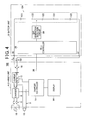
- FIG. 4 is a diagram showing the construction of the charging apparatus 100 according to this embodiment. Note that the parts shown in FIG. 1 are denoted by the same reference numerals in FIG. 4 and not described.
- the charging apparatus 100 of this embodiment includes a gas generation detection circuit 50. This gas generation detection circuit 50 detects gas generation in any one of the secondary cells 122 during charging and outputs to a cell controller 38. The cell controller 38 outputs to a charger controller 10 via a signal line 20 in the case of detecting gas generation.
- the charger controller 10 continues charging while reducing a charging current Ic until gas generation is stopped every time gas generation is detected during charging.
- the charging current Ic falls below the lower limit charging current value Ith
- a process similar to that after Step S10 of FIG. 2 described in the first embodiment is performed. Namely, when detecting that the charging current Ic falls to or below the lower limit charging current value Ith (Step S10: YES), the charger controller 10 continues charging while maintaining the charging current Ic at the lower limit charging current value Ith (Step S11).
- Step S12 When the charge amount Wc into the cell group 24 becomes equal to the discharge amount Wd during a non-charging period before the start of charging (Step S12: YES), the charger controller 10 stops charging while setting a charging state of the cell group 124 at a zero current charging state (Step S13), thereby ending the charging process.
- charging of the cell group 24 is stopped when the charged amount Wc becomes equal to the discharge amount Wd during a charging period similar to the first embodiment.
- charging can be carried out in just proportion and, particularly, overcharge can be reliably prevented since there is no likelihood of charging beyond the discharge amount Wd.
- an increase in internal resistance of each secondary cell 122 is suppressed since gas generation in the secondary cell 122 is suppressed during charging.
- waste of charging power accompanying this increase in internal resistance is suppressed and charging efficiency is improved.
- the gas generation detection circuit 50 may directly detect whether or not gas is being generated using a gas sensor or the like or may monitor the cell voltage Vb of each secondary cell 122 and indirectly detect gas generation by detecting that the cell voltage Vb has reached a specified voltage at which gas is generated from the secondary cell 122. Further, if the gas generation detection circuit 50 directly detects whether or not gas is being generated using a sensor or the like, the charger controller 10 may judge the stop of the gas generation based on a detection result of this gas generation detection circuit 50 or may indirectly detect the stop of the gas generation by comparing a specified cell voltage at which gas generation is stopped and the cell voltage Vb of the secondary cell 122.
- the above embodiments are to be understood as illustrative examples of the present invention and can be arbitrarily modified and applied within the scope of the present invention.
- overconsumption of charging power in the overcharge protection circuit 26 during charging and overconsumption of charging power accompanying gas generation in the secondary cells 122 during charging are suppressed in the above embodiments.
- the present invention can also be applied to charge such a cell group. Namely, in the case of power consumption caused by the power consumption factor during charging, charging may be continued with the charging current reduced until this consumption is stopped.
Landscapes
- Engineering & Computer Science (AREA)
- Manufacturing & Machinery (AREA)
- Chemical & Material Sciences (AREA)
- Chemical Kinetics & Catalysis (AREA)
- Electrochemistry (AREA)
- General Chemical & Material Sciences (AREA)
- Power Engineering (AREA)
- Microelectronics & Electronic Packaging (AREA)
- Charge And Discharge Circuits For Batteries Or The Like (AREA)
- Secondary Cells (AREA)
Applications Claiming Priority (2)
| Application Number | Priority Date | Filing Date | Title |
|---|---|---|---|
| JP2008043468A JP4499164B2 (ja) | 2008-02-25 | 2008-02-25 | 充電装置及び充電方法 |
| PCT/JP2009/000595 WO2009107336A1 (ja) | 2008-02-25 | 2009-02-16 | 充電装置及び充電方法 |
Publications (2)
| Publication Number | Publication Date |
|---|---|
| EP2249451A1 true EP2249451A1 (de) | 2010-11-10 |
| EP2249451A4 EP2249451A4 (de) | 2016-04-06 |
Family
ID=41015743
Family Applications (1)
| Application Number | Title | Priority Date | Filing Date |
|---|---|---|---|
| EP09715764.8A Withdrawn EP2249451A4 (de) | 2008-02-25 | 2009-02-16 | Aufladevorrichtung und aufladeverfahren |
Country Status (6)
| Country | Link |
|---|---|
| US (1) | US8305038B2 (de) |
| EP (1) | EP2249451A4 (de) |
| JP (1) | JP4499164B2 (de) |
| KR (1) | KR101489027B1 (de) |
| CN (1) | CN101960689B (de) |
| WO (1) | WO2009107336A1 (de) |
Families Citing this family (21)
| Publication number | Priority date | Publication date | Assignee | Title |
|---|---|---|---|---|
| JP5657257B2 (ja) * | 2009-03-13 | 2015-01-21 | 株式会社東芝 | 充電システム |
| JPWO2011118484A1 (ja) * | 2010-03-24 | 2013-07-04 | 株式会社Gsユアサ | 二次電池システム |
| DE102010029427A1 (de) * | 2010-05-28 | 2011-12-01 | Siemens Aktiengesellschaft | Energiespeicheranordnung |
| KR101216898B1 (ko) | 2011-04-22 | 2012-12-28 | 주식회사 현대케피코 | 배터리의 상태 추정 시스템 및 방법 |
| US8816639B2 (en) * | 2011-06-02 | 2014-08-26 | Aerojet Rocketdyne Of De, Inc. | Charge balancing topology |
| US8769327B2 (en) | 2011-10-04 | 2014-07-01 | Advanergy, Inc. | Battery charger management system and method for controlling a charge current by indirectly determining the type and characteristics of a battery via a current consumed by a charger |
| JPWO2013179599A1 (ja) * | 2012-06-01 | 2016-01-18 | パナソニックIpマネジメント株式会社 | 発電システムおよびその制御方法、並びに、蓄電池システムおよびその運用方法 |
| WO2013184695A1 (en) * | 2012-06-04 | 2013-12-12 | Advanergy, Inc. | Battery charger management system and method |
| BR112015002359B1 (pt) * | 2012-08-02 | 2021-05-04 | Nissan Motor Co., Ltd | sistema de gerenciamento de carregamento de bateria de veículo autoguiado e método de gerenciamento de carregamento de bateria |
| US9325192B2 (en) * | 2012-08-02 | 2016-04-26 | Nissan Motor Co., Ltd. | Battery charging management system for automated guided vehicle and battery charging management method for automated guided vehicle |
| CN104103867B (zh) * | 2013-04-03 | 2016-07-06 | 力博特公司 | 控制智能电池充电的方法、电池控制器及智能电池 |
| CN104252743A (zh) * | 2013-06-26 | 2014-12-31 | 比亚迪股份有限公司 | 充电计费方法及装置 |
| US9403443B2 (en) * | 2014-01-14 | 2016-08-02 | Ford Global Technologies, Llc | Charge balance system and method |
| JP5920639B2 (ja) * | 2014-02-25 | 2016-05-18 | トヨタ自動車株式会社 | 非水電解質二次電池の製造方法 |
| CN103795126B (zh) * | 2014-03-03 | 2016-08-17 | 无锡金雨电子科技有限公司 | 脉冲式充电方法和装置 |
| KR101587713B1 (ko) * | 2014-05-20 | 2016-01-21 | 에너지 컨트롤 리미티드 | 과충전 방지 장치를 가지는 2차 배터리 |
| TWI661650B (zh) * | 2018-03-23 | 2019-06-01 | 加百裕工業股份有限公司 | 並聯電池系統及方法 |
| CN112018831B (zh) * | 2019-05-28 | 2023-06-16 | 荣耀终端有限公司 | 一种充电控制方法、充电控制装置及电子设备 |
| CN110350632B (zh) * | 2019-08-20 | 2024-09-03 | 深圳市道通智能航空技术股份有限公司 | 一种电池均衡自放电电路和无人机 |
| CN111129630B (zh) * | 2019-12-30 | 2021-07-06 | 深圳市科陆电子科技股份有限公司 | 储能系统的能效优化方法 |
| CN116190829A (zh) * | 2023-02-22 | 2023-05-30 | 深圳市拓邦锂电池有限公司 | 电池预处理方法、装置、计算机设备和存储介质 |
Family Cites Families (30)
| Publication number | Priority date | Publication date | Assignee | Title |
|---|---|---|---|---|
| US4371825A (en) * | 1981-06-04 | 1983-02-01 | Energy Development Associates, Inc. | Method of minimizing the effects of parasitic currents |
| JPH086958B2 (ja) | 1988-07-25 | 1996-01-29 | 三洋電機株式会社 | 遠隔制御装置 |
| JPH0233556U (de) * | 1988-08-23 | 1990-03-02 | ||
| JP3244737B2 (ja) * | 1991-12-24 | 2002-01-07 | 松下電工株式会社 | 電池の寿命報知装置 |
| US5475294A (en) * | 1991-12-27 | 1995-12-12 | Nippon Densan Corporation | Charge controller for battery charger |
| JPH0779504A (ja) * | 1993-09-07 | 1995-03-20 | Kubota Corp | 小型電動車 |
| US5900720A (en) * | 1993-09-10 | 1999-05-04 | Kallman; William R. | Micro-electronic power supply for electrochromic eyewear |
| JPH07264780A (ja) * | 1994-03-18 | 1995-10-13 | Nissan Motor Co Ltd | 組電池の充放電制御装置 |
| JPH07336905A (ja) * | 1994-06-08 | 1995-12-22 | Nissan Motor Co Ltd | 組電池の充電装置 |
| FR2725849B1 (fr) * | 1994-10-18 | 1996-12-20 | Accumulateurs Fixes | Procede de regulation de la charge d'un ensemble accumulateur electrique et agencement mettant en oeuvre ce procede |
| US6104165A (en) * | 1995-06-16 | 2000-08-15 | Zip Charge Corporation | Multi-stage battery charging system |
| JP3496360B2 (ja) * | 1995-09-14 | 2004-02-09 | 日産自動車株式会社 | 組電池の充電制御装置 |
| JP3503295B2 (ja) * | 1995-09-18 | 2004-03-02 | 日産自動車株式会社 | 組電池の充電制御方法および装置 |
| JPH09308126A (ja) * | 1996-05-17 | 1997-11-28 | Nissan Motor Co Ltd | 充電装置 |
| US6040685A (en) * | 1996-08-16 | 2000-03-21 | Total Battery Management, Inc. | Energy transfer and equalization in rechargeable lithium batteries |
| JP3767767B2 (ja) * | 1997-11-28 | 2006-04-19 | ソニー株式会社 | 充電制御方法及び充電制御装置 |
| JPH11329510A (ja) * | 1998-05-11 | 1999-11-30 | Matsushita Electric Ind Co Ltd | 電池の充電方法 |
| US6642693B2 (en) * | 2000-11-21 | 2003-11-04 | Nagano Japan Radio Co., Ltd. | Voltage equalizing apparatus for battery devices |
| JP3767422B2 (ja) * | 2001-06-01 | 2006-04-19 | 日産自動車株式会社 | 充電方法および充電装置 |
| JP3767438B2 (ja) | 2001-09-07 | 2006-04-19 | 日産自動車株式会社 | 充電装置および充電方法 |
| JP4343173B2 (ja) * | 2002-11-25 | 2009-10-14 | ティアックス エルエルシー | 直列接続された電気エネルギー貯蔵ユニット間の充電状態を均等化するバッテリーセル平衡化システム |
| CA2539723A1 (en) * | 2003-09-22 | 2005-04-07 | Valence Technology, Inc. | Electrical systems, power supply apparatuses, and power supply operations methods |
| JP3832660B2 (ja) * | 2003-10-29 | 2006-10-11 | 株式会社Nttファシリティーズ | 充電装置 |
| US20060022646A1 (en) * | 2004-07-28 | 2006-02-02 | Moore Stephen W | Method for battery cold-temperature warm-up mechanism using cell equilization hardware |
| US7525285B2 (en) * | 2004-11-11 | 2009-04-28 | Lg Chem, Ltd. | Method and system for cell equalization using state of charge |
| JP4186916B2 (ja) * | 2004-11-18 | 2008-11-26 | 株式会社デンソー | 組電池管理装置 |
| JP4628284B2 (ja) * | 2006-03-01 | 2011-02-09 | エナックス株式会社 | 二次電池の充電方法及び装置 |
| JP2008010295A (ja) * | 2006-06-29 | 2008-01-17 | Hokuriku Electric Power Co Inc:The | 二次電池の保温方法及び保温装置 |
| CN101325272B (zh) * | 2007-06-11 | 2010-06-02 | 吴文恺 | 平衡充电方法及其装置 |
| US7830120B2 (en) * | 2007-09-18 | 2010-11-09 | Nexergy, Inc. | Low side N-channel FET protection circuit |
-
2008
- 2008-02-25 JP JP2008043468A patent/JP4499164B2/ja active Active
-
2009
- 2009-02-16 EP EP09715764.8A patent/EP2249451A4/de not_active Withdrawn
- 2009-02-16 CN CN2009801063984A patent/CN101960689B/zh not_active Expired - Fee Related
- 2009-02-16 US US12/918,974 patent/US8305038B2/en not_active Expired - Fee Related
- 2009-02-16 KR KR20107018767A patent/KR101489027B1/ko not_active Expired - Fee Related
- 2009-02-16 WO PCT/JP2009/000595 patent/WO2009107336A1/ja not_active Ceased
Non-Patent Citations (1)
| Title |
|---|
| See references of WO2009107336A1 * |
Also Published As
| Publication number | Publication date |
|---|---|
| KR20100114097A (ko) | 2010-10-22 |
| KR101489027B1 (ko) | 2015-02-02 |
| WO2009107336A1 (ja) | 2009-09-03 |
| US20110169453A1 (en) | 2011-07-14 |
| EP2249451A4 (de) | 2016-04-06 |
| CN101960689A (zh) | 2011-01-26 |
| JP4499164B2 (ja) | 2010-07-07 |
| CN101960689B (zh) | 2013-10-30 |
| US8305038B2 (en) | 2012-11-06 |
| JP2009201337A (ja) | 2009-09-03 |
Similar Documents
| Publication | Publication Date | Title |
|---|---|---|
| US8810193B2 (en) | Charging apparatus having gas generation detector and charging method for the same | |
| US8305038B2 (en) | Charging apparatus and charging method | |
| KR101526646B1 (ko) | 충전 장치 | |
| KR100885291B1 (ko) | 충전 장치 | |
| CN1998110B (zh) | 平衡锂离子或锂聚合物电池的充电的方法 | |
| EP2629388A1 (de) | Leistungsverwaltungssystem | |
| EP2629387A1 (de) | Leistungsverwaltungssystem | |
| US9906052B2 (en) | Power supply device | |
| JP2008527963A (ja) | リチウムイオンまたはリチウムポリマーのバッテリをバランス充電するための方法 | |
| US20150048795A1 (en) | Charge control apparatus and charge control method | |
| US8076905B2 (en) | Battery charging method and device thereof | |
| KR20230022012A (ko) | 배터리의 열화 저감방법 및 그 방법을 제공하는 배터리 관리 시스템 | |
| JP2013146160A (ja) | 組電池の充電制御システムおよび充電制御方法 | |
| US20070222412A1 (en) | Device and method for the automatic regulation of the charging of an electrochemical generator | |
| JP2025091656A (ja) | 内部短絡検出装置、蓄電デバイス、内部短絡検出方法およびプログラム |
Legal Events
| Date | Code | Title | Description |
|---|---|---|---|
| PUAI | Public reference made under article 153(3) epc to a published international application that has entered the european phase |
Free format text: ORIGINAL CODE: 0009012 |
|
| 17P | Request for examination filed |
Effective date: 20100823 |
|
| AK | Designated contracting states |
Kind code of ref document: A1 Designated state(s): AT BE BG CH CY CZ DE DK EE ES FI FR GB GR HR HU IE IS IT LI LT LU LV MC MK MT NL NO PL PT RO SE SI SK TR |
|
| AX | Request for extension of the european patent |
Extension state: AL BA RS |
|
| DAX | Request for extension of the european patent (deleted) | ||
| RA4 | Supplementary search report drawn up and despatched (corrected) |
Effective date: 20160304 |
|
| RIC1 | Information provided on ipc code assigned before grant |
Ipc: H02J 7/02 20060101ALI20160229BHEP Ipc: H02J 7/00 20060101AFI20160229BHEP Ipc: H01M 10/44 20060101ALI20160229BHEP Ipc: H02J 7/04 20060101ALI20160229BHEP Ipc: H02J 7/34 20060101ALI20160229BHEP |
|
| STAA | Information on the status of an ep patent application or granted ep patent |
Free format text: STATUS: THE APPLICATION HAS BEEN WITHDRAWN |
|
| 18W | Application withdrawn |
Effective date: 20160712 |