EP2249213B1 - Verringerung der Verschmutzung auf Bildelementen mittels UV-Ozonbehandlung - Google Patents
Verringerung der Verschmutzung auf Bildelementen mittels UV-Ozonbehandlung Download PDFInfo
- Publication number
- EP2249213B1 EP2249213B1 EP10161910.4A EP10161910A EP2249213B1 EP 2249213 B1 EP2249213 B1 EP 2249213B1 EP 10161910 A EP10161910 A EP 10161910A EP 2249213 B1 EP2249213 B1 EP 2249213B1
- Authority
- EP
- European Patent Office
- Prior art keywords
- contaminated
- lamp
- image
- contamination
- image member
- Prior art date
- Legal status (The legal status is an assumption and is not a legal conclusion. Google has not performed a legal analysis and makes no representation as to the accuracy of the status listed.)
- Not-in-force
Links
- CBENFWSGALASAD-UHFFFAOYSA-N Ozone Chemical compound [O-][O+]=O CBENFWSGALASAD-UHFFFAOYSA-N 0.000 title claims description 42
- 238000011109 contamination Methods 0.000 title claims description 29
- 238000000034 method Methods 0.000 claims description 37
- 230000005855 radiation Effects 0.000 claims description 26
- 239000011347 resin Substances 0.000 claims description 15
- 229920005989 resin Polymers 0.000 claims description 15
- 238000005202 decontamination Methods 0.000 claims description 12
- 230000003588 decontaminative effect Effects 0.000 claims description 11
- 239000004205 dimethyl polysiloxane Substances 0.000 claims description 10
- 229920000435 poly(dimethylsiloxane) Polymers 0.000 claims description 10
- 239000003795 chemical substances by application Substances 0.000 claims description 9
- 239000000463 material Substances 0.000 claims description 9
- HJSYJHHRQVHHMQ-TYYBGVCCSA-L zinc;(e)-but-2-enedioate Chemical compound [Zn+2].[O-]C(=O)\C=C\C([O-])=O HJSYJHHRQVHHMQ-TYYBGVCCSA-L 0.000 claims description 9
- 238000003384 imaging method Methods 0.000 claims description 8
- -1 thermoelastomers Polymers 0.000 claims description 7
- 229910000497 Amalgam Inorganic materials 0.000 claims description 6
- 239000006227 byproduct Substances 0.000 claims description 6
- 230000001678 irradiating effect Effects 0.000 claims description 6
- 229920000728 polyester Polymers 0.000 claims description 6
- 229920002313 fluoropolymer Polymers 0.000 claims description 5
- QSHDDOUJBYECFT-UHFFFAOYSA-N mercury Chemical compound [Hg] QSHDDOUJBYECFT-UHFFFAOYSA-N 0.000 claims description 5
- 229910052753 mercury Inorganic materials 0.000 claims description 5
- 239000004811 fluoropolymer Substances 0.000 claims description 4
- 238000010521 absorption reaction Methods 0.000 claims description 3
- 229920002379 silicone rubber Polymers 0.000 claims description 3
- 235000013870 dimethyl polysiloxane Nutrition 0.000 claims 3
- CXQXSVUQTKDNFP-UHFFFAOYSA-N octamethyltrisiloxane Chemical compound C[Si](C)(C)O[Si](C)(C)O[Si](C)(C)C CXQXSVUQTKDNFP-UHFFFAOYSA-N 0.000 claims 3
- 238000004987 plasma desorption mass spectroscopy Methods 0.000 claims 3
- 239000003921 oil Substances 0.000 description 9
- 239000000758 substrate Substances 0.000 description 9
- 238000004381 surface treatment Methods 0.000 description 9
- 239000000356 contaminant Substances 0.000 description 8
- QVGXLLKOCUKJST-UHFFFAOYSA-N atomic oxygen Chemical compound [O] QVGXLLKOCUKJST-UHFFFAOYSA-N 0.000 description 5
- 229920002449 FKM Polymers 0.000 description 4
- 238000004140 cleaning Methods 0.000 description 4
- 239000001301 oxygen Substances 0.000 description 4
- 229910052760 oxygen Inorganic materials 0.000 description 4
- 238000005102 attenuated total reflection Methods 0.000 description 3
- 238000002474 experimental method Methods 0.000 description 3
- 108091008695 photoreceptors Proteins 0.000 description 3
- 238000005033 Fourier transform infrared spectroscopy Methods 0.000 description 2
- 239000000654 additive Substances 0.000 description 2
- 239000011324 bead Substances 0.000 description 2
- 238000010586 diagram Methods 0.000 description 2
- 238000005516 engineering process Methods 0.000 description 2
- 150000002500 ions Chemical class 0.000 description 2
- 230000007935 neutral effect Effects 0.000 description 2
- 239000002245 particle Substances 0.000 description 2
- 239000010453 quartz Substances 0.000 description 2
- 239000004065 semiconductor Substances 0.000 description 2
- VYPSYNLAJGMNEJ-UHFFFAOYSA-N silicon dioxide Inorganic materials O=[Si]=O VYPSYNLAJGMNEJ-UHFFFAOYSA-N 0.000 description 2
- 229920002545 silicone oil Polymers 0.000 description 2
- 230000003213 activating effect Effects 0.000 description 1
- 230000015572 biosynthetic process Effects 0.000 description 1
- 239000007795 chemical reaction product Substances 0.000 description 1
- 230000007423 decrease Effects 0.000 description 1
- 230000007547 defect Effects 0.000 description 1
- 230000000694 effects Effects 0.000 description 1
- 229920001973 fluoroelastomer Polymers 0.000 description 1
- 239000000049 pigment Substances 0.000 description 1
- 239000000843 powder Substances 0.000 description 1
- 239000000047 product Substances 0.000 description 1
- 238000010186 staining Methods 0.000 description 1
- 229920001169 thermoplastic Polymers 0.000 description 1
- 239000004416 thermosoftening plastic Substances 0.000 description 1
- 239000010409 thin film Substances 0.000 description 1
- XOOUIPVCVHRTMJ-UHFFFAOYSA-L zinc stearate Chemical compound [Zn+2].CCCCCCCCCCCCCCCCCC([O-])=O.CCCCCCCCCCCCCCCCCC([O-])=O XOOUIPVCVHRTMJ-UHFFFAOYSA-L 0.000 description 1
Images


Classifications
-
- G—PHYSICS
- G03—PHOTOGRAPHY; CINEMATOGRAPHY; ANALOGOUS TECHNIQUES USING WAVES OTHER THAN OPTICAL WAVES; ELECTROGRAPHY; HOLOGRAPHY
- G03G—ELECTROGRAPHY; ELECTROPHOTOGRAPHY; MAGNETOGRAPHY
- G03G15/00—Apparatus for electrographic processes using a charge pattern
- G03G15/20—Apparatus for electrographic processes using a charge pattern for fixing, e.g. by using heat
- G03G15/2003—Apparatus for electrographic processes using a charge pattern for fixing, e.g. by using heat using heat
- G03G15/2014—Apparatus for electrographic processes using a charge pattern for fixing, e.g. by using heat using heat using contact heat
- G03G15/2017—Structural details of the fixing unit in general, e.g. cooling means, heat shielding means
- G03G15/2025—Structural details of the fixing unit in general, e.g. cooling means, heat shielding means with special means for lubricating and/or cleaning the fixing unit, e.g. applying offset preventing fluid
Definitions
- the present invention relates generally to materials and methods in electrophotography and, more particularly, to surface treatment systems and methods for reducing contamination built-up on image members in an electrophotographic printing machine.
- electrostatic latent images are formed on a xerographic surface by uniformly charging a charge retentive surface, such as a photoreceptor.
- a charge retentive surface such as a photoreceptor.
- the charged area is then selectively dissipated in a pattern of activating radiation corresponding to the original image.
- the latent charge pattern remaining on the surface corresponds to the area not exposed by radiation and is visualized by passing the photoreceptor by one or more developer housings.
- the developer housings typically include thermoplastic toner that adheres to the charge pattern by electrostatic attraction.
- the developed image is then fixed to the imaging surface or transferred to a receiving substrate, such as a paper sheet, to which it is fixed by a suitable fusing technique resulting in a xerographic print or toner-based print.
- Conventional xerographic machines include a fuser roll and a pressure roll in a fusing unit whose role is to fuse the toner to the paper substrate under heat and pressure.
- release agents are applied to the fuser roll to ensure and maintain good release properties of the fuser roll.
- the release agents include non-functional silicone oils, or mercapto-/amino- functional silicone oils, such as for example polydimethylsiloxane (PDMS) oils, that are applied as thin films of low surface energy to prevent toner offset on the fuser roll.
- PDMS polydimethylsiloxane
- the image members can include, but are not limited to, a fuser member such as a fuser roll, a pressure member, a heat member, a donor member or other imaging or fixing members used in xerographic printers and copiers.
- a method for treating a surface of an image member can be contaminated from a printing process by, for example, a release agent and/or a toner material.
- ultraviolet radiation can be used to irradiate the surface at one or more UV wavelengths, applying a combined UV radiation and ozone treatment.
- a method for treating a surface of an image member can be used to irradiate a contaminated surface of the image member at one or more wavelengths to apply UV radiation and ozone treatment.
- the at least one UV light source can be positioned a distance d away from the contaminated surface.
- the contaminated surface of the image member can be irradiated at a first UV wavelength and at a second UV wavelength using a UV light source that is placed at a distance d away from the contaminated surface.
- the irradiation with one of the first and second UV wavelengths can generate ozone to help with decontaminating the contaminated surface of the image member.
- an electrophotographic system for decontaminating a contaminated surface.
- Such system can include an image member and at least one light source positioned at a distance d from the image member. The distance d can be selected to permit the light source to irradiate and decontaminate a surface of the image member, which is contaminated by a release agent and/or a toner material.
- the light source can be capable of irradiating at one or more UV wavelengths so as to apply a combined UV and ozone treatment to the contaminated surface of the image member.
- Exemplary embodiments provide a method and a system for reducing contamination built-up on surfaces of image members within a printing system.
- the image members such as a fuser member, a pressure member, a heat member, and/or a donor member, can be contaminated from one or more printing processes by, for example, a release agent such as gelled oil, and/or a toner material such as particles or carrier beads in the toner.
- the contaminated surfaces of image members can be decontaminated by a surface treatment.
- the surface treatment can include a combined UV radiation and ozone (or UV/ozone) treatment using at least one lamp Specifically, the lamp can irradiate the contaminated surfaces at one or more UV wavelengths providing UV radiation energy and ozone to the surfaces so as to reduce or eliminate contamination thereon. In various embodiments, the lamp can be positioned a distance d away from the contaminated surface during the surface treatment.
- UV radiation at specific wavelengths can break contaminant molecules on surfaces to decontaminate the image members.
- the decontamination effect of UV radiation can be enhanced by the presence of ozone.
- Ozone can be generated as a by-product of UV radiation of a particular wavelength which dissociates the atmospheric oxygen.
- the disclosed surface treatment can be conducted at any time following one or more printing processes and can include UV radiation having two or more distinct wavelengths, so that the amount of contamination on image member surfaces can be reduced by the combined treatment of UV radiation energy and ozone.
- the UV/ozone treatment used towards removing some organic contamination and the removal mechanism has been recognized and described in the Journal of Vacuum Science and Technology (Vol.11, pages 474-475, 1974) by Sowell et al., entitled “Surface Cleaning by Ultraviolet Radiation", and in the Handbook of Semiconductor Wafer Cleaning Technology by J.R.Vig, entitled “Ultraviolet-ozone Cleaning of Semiconductor Surfaces ".
- UV radiation comprised of a first wavelength ⁇ 1 can be provided by an UV light source such a UV output lamp. This radiation will result in ozone formation from atmospheric oxygen.
- the first wavelength ⁇ 1 can be in a range from about 100 nm to about 210 nm. In a specific example, ⁇ 1 can be about 185 nm.
- a UV radiation comprised of a second wavelength ⁇ 2 can be provided by the same or different UV light source such as an UV output lamp and can interact with most organic contaminants breaking them into free radicals and excited molecules.
- the second group of wavelengths ⁇ 2 can be in a range from about 210 nm to about 315 nm. In a specific example, ⁇ 2 can be about 254 nm.
- the wavelengths used for treating the surface can also be outside of these ranges as described above.
- the decontamination efficiency can be affected by various factors, for example, the intensity and power of the UV light source as well as the exposure time to the UV radiation, along with the distance d between the UV light source and the contaminated surface.
- FIG. 1 depicts a block diagram for an exemplary decontamination system in accordance with the present teachings. It should be readily apparent to one of ordinary skill in the art that the system comprising of a UV light source and a contaminated substrate, depicted in FIG. 1 represents a generalized schematic illustration and that other components/ devices can be added or existing components/ devices can be removed or modified.
- the system depicted in FIG. 1 can include a light source 110, and a contaminated surface 120.
- the light source 110 can be placed or positioned spacing away from the contaminated surface at a distance d .
- the UV light source 110 can include, for example, at least one UV light source, and can irradiate at various wavelengths.
- the wavelengths can include, for example, a first wavelength ranging from about 100 nm to about 210 nm, and a second wavelength ranging from about 210 nm to about 315 nm, such that the irradiation at one of first and second wavelengths can generate ozone.
- a UV/ozone treatment can then be applied to the contaminated surface 120.
- the light source 110 can include, for example, a mercury lamp, an amalgam lamp or their combinations.
- the power of the UV output can be controlled by the light source 110.
- the light source 110 can include a low pressure mercury lamp including, for example, a 54 mW/cm 2 -quartz tube mercury Pen Ray Lamp (Cole-Parmer, Vernon Hills, IL).
- the light source 110 can include a high power amalgam lamp, for example, having a UV output power of about 150W (3W/cm), which can be available from Heraeus Noblelight (Hanau, Germany).
- the contaminated surface 120 can include a surface of image members of a xerographic imaging apparatus or a printer.
- the image members can include, but are not limited to a fuser member, a pressure or heat member, and/or a donor release member.
- the image member can be in a form of a cylinder, a belt or a sheet and can have an outermost (or topcoat) surface made of materials including, but not limited to, fluoropolymers such as fluoroelastomers, fluoroplastics, fluororesins, silicone elastomers, thermoelastomers, resins, and/or any other materials that can be used in the electrophotographic devices and processes.
- the image member can have an outermost surface of fluoropolymer such as VITON® from E.I. DuPont de Nemours, Inc. (Wilmington, DE), which may be contaminated by toner materials and/or fusing release agents during printing.
- fluoropolymer such as VITON® from E.I. DuPont de Nemours, Inc. (Wilmington, DE)
- the contaminated surface 120 can be decontaminated using UV radiation provided from the light source 110 to allow a UV/ozone treatment.
- the UV/ozone treatment can be used to decontaminate image member surfaces that are contaminated from printing cycles.
- the combined use of UV radiation energy and ozone can be conducted simultaneously, sequentially or separately. Various treatment times or exposure times can be used accordingly.
- the contamination on the contaminated surface 120 can be irradiated at a first wavelength ⁇ 1 of about 185 nm that can be absorbed by the atmospheric oxygen to dissociate the atmospheric oxygen into atomic oxygen, which can be subsequently recombine to generate an active product such as ozone.
- the UV light source 110 can output a UV radiation at a second wavelength ⁇ 2 of about 254 nm that can break contaminant molecules into intermediate by- products, for example, ions, free radicals, and/or excited/neutral molecules.
- the intermediate by-products of ions, free radicals, excited molecules and/or neutral molecules can then react with the ozone to form, for example, CO 2 , N 2 , H 2 O etc.
- the reaction product can be removed from the contaminated surface, completing the decontamination process.
- the light source 110 can be placed a distance d away from the contaminated surface 120.
- the distance d there-between can affect treatment efficiency of UV/ozone, as the lamp intensity decreases when increasing the distance d .
- the distance d can be selected to allow the UV light source to efficiently treat or reduce contamination on the contaminated surface and, meanwhile, to avoid excessive absorption of radiations from the light source 110 by the ozone.
- the distance d can be on order of a few millimeters to effectively decontaminate the contaminated member and to avoid the excessive absorption of UV radiation in air. In some embodiments, the distance d can be from about 0 millimeters to about 20 millimeters. In other embodiments, the distance d can be no more than about 5 millimeters. Various embodiments, however, can include a distance d that is outside of these ranges.
- the irradiation time or the exposure time of the contaminated surface 120 can also be controlled to render enough time for treating the surface and to reduce contamination.
- the irradiation time can be, for example, about 1 hour or shorter.
- the irradiation time can be about 20 minutes or shorter.
- the irradiation time can be from about 5 to about 20 minutes.
- the treatment efficiency and/or the irradiation time can be affected by the UV output power of the light source 110.
- the treatment time can be reduced to seconds.
- an amalgam lamp with a high UV output power of about 150W (3W/cm) available from Heraeus Noblelight, Hanau, Germany
- the efficiency of the surface treatment can be significantly increased for all types of contaminants that result from printing processes, by simply reducing the exposure time from about 20 minutes, provided that a low UV output Pen Ray lamp (54mW/cm 2 ) is used, to about 100 seconds provided that a high UV output Heraeus lamp (3W/cm) is used.
- the treatment time can be reduced even further, for example, between 0 and about 1 second for much higher UV output lamps.
- the contaminated surface 120 can be a contaminated outermost surface of a fuser member and can be contaminated from one or more organic contaminants from printing processes including, but not limited to, a release agent such as gelled fuser oil, particles or carrier beads in the toner, which include, for example, polyester toner resin and zinc fumarate from zinc stearate additives in the toner.
- a release agent such as gelled fuser oil, particles or carrier beads in the toner, which include, for example, polyester toner resin and zinc fumarate from zinc stearate additives in the toner.
- a fusing system can include, for example, a fuser roll, a pressure roll and a substrate transport.
- the substrate transport can direct the image-receiving substrate (e.g., a photoreceptor) with a toner powder image through a nip between the fuser roll that is being heated at a certain temperature and the pressure roll, where the toner image can be affixed to the image receiving substrate.
- image-receiving substrate e.g., a photoreceptor
- the toner present on the image receiving substrate can fail to penetrate, e.g., the paper and can be transferred to the fuser roll instead.
- the toner material can stick to the roll and build-up on the fuser roll as contamination. Such contamination can come in contact with subsequent substrates that pass through the fusing system, and thus affecting the image quality of the final toner image.
- the contamination that builds-up on the fuser roll can be treated using the system and method shown in FIG. 1 by irradiating the contaminated surface at one or more appropriate UV wavelengths, applying combined UV/ozone treatment to reduce or eliminate contaminants on contaminated fuser roll surfaces.
- a method for reducing an amount of PDMS gelled oil contamination built-up on an exemplary fuser roll by treating the contaminated surface with a combined ultraviolet radiation and ozone can be provided by one or more UV light sources emitting at least a first wavelength of about 100 nm to about 210 nm and a second wavelength of about 210 nm to about 315 nm.
- a method for reducing an amount of toner resin contamination built-up on an exemplary fuser roll by treating the contaminated surface with a combined ultraviolet radiation and ozone can be provided by one or more UV light sources emitting at least a first wavelength of about 100 nm to about 210 nm and a second wavelength of about 210 nm to about 315 nm.
- a method for reducing an amount of zinc fumarate contamination built-up on an exemplary fuser roll by treating the contaminated surface with a combined ultraviolet radiation and ozone can be provided by one or more UV light sources emitting at least a first of wavelength of about 100 nm to about 210 nm and a second wavelength of about 210 nm to about 315 nm.
- the system and method shown in FIG. 1 can be fast, fairly inexpensive and easy solutions to be implemented in the electrophotographic field.
- the light source can be permanently installed in an image member assembly, such as a fuser assembly, and used for surface cleaning cycles after a certain number of printing jobs.
- the light source can be turned off while printing so as to reduce unnecessary ozone generation.
- the UV/ozone decontamination experiments were carried out on a VITON® fuser roll which underwent 25,000 prints testing and where a 13-coloured toner stripe target was used.
- the UV/ozone treatment was performed using a 54 mW/cm 2 quartz tube mercury Pen Ray Lamp (Cole-Parmer) to irradiate the VITON® surface of the fuser roll at a first and second wavelength of about 254 nm and 185 nm respectively.
- the contaminated surface was treated by UV/ozone for about 20 minutes.
- a higher UV output Heraeus amalgam lamp, available from Hanau, Germany, with an output power of 3W/cm, was also used in the decontamination experiments carried out on a VITON® surface, which was exposed for about 100 seconds in this example.
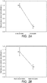
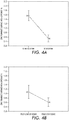
- FIGS. 2A-2B , FIGS. 3A-3B , and FIGS. 4A-4B show exemplary decontamination results for all three types of contaminants such as PDMS gelled fuser oil, polyester toner resin, and zinc fumarate, respectively.
- the results were characterized by the contaminated surface area coverage, which was measured by Attenuated Total Reflection (ATR) Fourier Transform Infrared (FT- IR) spectroscopy. Specifically, in order to show the contamination reduction, the amount of surface area coverage by each contaminant was measured before and after the UV/Ozone treatment.
- ATR Attenuated Total Reflection
- FT- IR Fourier Transform Infrared
- the contaminated surface areas of the PDMS gelled oil (see FIGS. 2A-2B ), the polyester toner resin (see FIGS. 3A-3B ), and the zinc fumarate (see FIGS. 4A-4B ) were significantly reduced from a high value M to a low value N after the UV/ozone treatment.
- two separate samples from the same contaminated fuser roll were cut and treated by UV/ozone using appropriate UV light sources and were measured by ATR FT-IR to examine the surface area coverage by the contamination of the PDMS gelled oil, the polyester toner resin and the zinc fumarate before and after the surface treatment.
- FIG. 2A , 3A and 4A were experimental results generated by a 20-minute-UV/ozone treatment using the low pressure Pen Ray Lamp, while FIG. 2B , 3B and 4B were experimental results generated by a 100-second-UV/ozone treatment using the high UV output Heraeus amalgam lamp.
Landscapes
- Physics & Mathematics (AREA)
- General Physics & Mathematics (AREA)
- Fixing For Electrophotography (AREA)
- Photosensitive Polymer And Photoresist Processing (AREA)
- Treatments Of Macromolecular Shaped Articles (AREA)
- Cleaning In Electrography (AREA)
Claims (13)
- Verfahren zur Behandlung einer Oberfläche eines Bildelements einer xerographischen Abbildungsvorrichtung, umfassend:- Bereitstellen eines Bildelements, wobei eine äußere Oberfläche des Bildelements ein oder mehrere Fluorpolymere, Silikonelastomere, Thermoelastomere, Harze und Kombinationen davon umfasst und von einem xerographischen Druckverfahren durch ein oder mehrere Trennmittel und Tonermaterial verunreinigt ist;- Abbilden eines oder mehrerer Artikel für die Wiedergabe unter Verwendung des Bildelements in der xerographischen Abbildungsvorrichtung; und- Bestrahlen der kontaminierten Oberfläche des Bildelements mit einer oder mehreren UV-Wellenlängen durch eine in der xerographischen Abbildungsvorrichtung angeordneten Lampe, um eine kombinierte UV- und Ozonbehandlung durchzuführen, um eine Verunreinigung der kontaminierten Oberfläche zu verringern, wobei die Verunreinigung Tonerharz, PDMS-geliertes Öl und Tonerharz-Nebenprodukte umfasst.
- Verfahren nach Anspruch 1, das ferner umfasst:- Bestrahlen der kontaminierten Oberfläche des Bildelements mit einer ersten UV-Wellenlänge, die in einem Bereich von etwa 100 nm bis etwa 210 nm liegt, und- Bestrahlen der kontaminierten Oberfläche mit einer zweiten UV-Wellenlänge, die in einem Bereich von etwa 210 nm bis etwa 315 nm liegt.
- Verfahren nach Anspruch 1, das ferner umfasst:Anordnen der Lampe in einem Abstand d entfernt von der kontaminierten Oberfläche, wobei die mindestens eine Lichtquelle mit der einen oder mehreren UV-Wellenlängen strahlt.
- Verfahren nach Anspruch 3, das ferner umfasst:Bestimmen des Abstands d auf der Grundlage einer Bestrahlungseffizienz, die die Dekontamination der kontaminierten Oberfläche optimiert und eine übermäßige Absorption der UV-Strahlung aus der UV-Lichtquelle durch das Ozon selbst beseitigt.
- Verfahren nach Anspruch 3, das ferner umfasst:Steuern einer Ausgabeleistung der Lampe, wobei die Lampe eine Quecksilberlampe, eine Amalgamlampe oder Kombinationen davon umfasst.
- Verfahren nach Anspruch 1, das ferner umfasst:Bestimmen einer Bestrahlungszeit auf der kontaminierten Oberfläche auf der Grundlage einer Bestrahlungsleistung der einen oder mehreren UV-Wellenlängen.
- Verfahren nach Anspruch 1, wobei die Bestrahlung der kontaminierten Oberfläche eine Menge einer auf eine Oberfläche eines Fixierelementes angesammelten Polyester-Tonerharz-Kontamination von einem oder mehreren Druckprozessen reduziert.
- Verfahren nach Anspruch 1, wobei die Bestrahlung der kontaminierten Oberfläche eine Menge einer auf einer Oberfläche eines Fixierelementes angesammelten PDMS-gelierten Ölkonamination von einem oder mehreren Druckprozessen reduziert.
- Verfahren nach Anspruch 1, wobei die Bestrahlung der kontaminierten Oberfläche eine Menge einer auf einer Oberfläche eines Fixierelementes angesammelten Zinkfumarat-Kontamination von einem oder mehreren Druckprozessen reduziert.
- Verfahren nach Anspruch 3, wobei der Abstand d zwischen der UV-Lichtquelle und der kontaminierten Oberfläche etwa 20 Millimeter oder weniger beträgt.
- Elektrophotographisches System, umfassend:- ein Bildelement mit einer äußeren Oberfläche, die ein oder mehrere Fluorpolymere, Silikonelastomere, Thermoelastomere, Harze und Kombinationen davon umfasst; und- eine Lampe, die in einem Abstand d von der Bildelementoberfläche innerhalb des elektrophotographischen Systems angeordnet ist, so dass es durch den Abstand d möglich ist, dass die Lichtquelle die Bildelementoberfläche von einem Trennmittel, einem Tonerharz, einem PDMS gelierten Öl und Tonerharz-Nebenprodukten und Zinkfumarat dekontaminiert,wobei die Lampe in der Lage ist, bei einer oder mehreren UV-Wellenlängen zu strahlen, um eine kombinierte UV- und Ozonbehandlung auf der Oberfläche des Bildelements durchzuführen.
- System nach Anspruch 11, wobei die eine oder mehrere UV-Wellenlängen eine erste UV-Wellenlänge im Bereich von etwa 100 nm bis etwa 210 nm und eine zweite Wellenlänge im Bereich von etwa 210 nm bis etwa 315 nm umfassen.
- System nach Anspruch 11, wobei das Bildelement ein Fixierelement, ein Druckelement, ein Heizelement oder ein Donorelement ist.
Applications Claiming Priority (1)
| Application Number | Priority Date | Filing Date | Title |
|---|---|---|---|
| US12/436,383 US8364054B2 (en) | 2009-05-06 | 2009-05-06 | Reduction of contamination on image members by UV ozone treatment |
Publications (3)
| Publication Number | Publication Date |
|---|---|
| EP2249213A2 EP2249213A2 (de) | 2010-11-10 |
| EP2249213A3 EP2249213A3 (de) | 2016-02-24 |
| EP2249213B1 true EP2249213B1 (de) | 2017-04-19 |
Family
ID=42711675
Family Applications (1)
| Application Number | Title | Priority Date | Filing Date |
|---|---|---|---|
| EP10161910.4A Not-in-force EP2249213B1 (de) | 2009-05-06 | 2010-05-04 | Verringerung der Verschmutzung auf Bildelementen mittels UV-Ozonbehandlung |
Country Status (4)
| Country | Link |
|---|---|
| US (1) | US8364054B2 (de) |
| EP (1) | EP2249213B1 (de) |
| JP (1) | JP2010262289A (de) |
| CA (1) | CA2702912C (de) |
Families Citing this family (3)
| Publication number | Priority date | Publication date | Assignee | Title |
|---|---|---|---|---|
| JP4630887B2 (ja) * | 2007-05-31 | 2011-02-09 | 住友ゴム工業株式会社 | 画像形成部材の再生方法 |
| JP2017181581A (ja) * | 2016-03-28 | 2017-10-05 | 富士ゼロックス株式会社 | 画像形成装置 |
| CN113022117B (zh) * | 2021-03-03 | 2022-11-15 | 山东朝泰实业有限公司 | 基于环保水墨打底的冷光源led纹路胶辊转印印刷系统 |
Citations (1)
| Publication number | Priority date | Publication date | Assignee | Title |
|---|---|---|---|---|
| US20080299483A1 (en) * | 2007-05-31 | 2008-12-04 | Sumitomo Rubber Industries, Ltd. | Method for recycling an image-forming member |
Family Cites Families (6)
| Publication number | Priority date | Publication date | Assignee | Title |
|---|---|---|---|---|
| US60000A (en) * | 1866-11-27 | Philandek haklow | ||
| DE4241575A1 (de) * | 1992-12-10 | 1994-06-16 | Baldwin Gegenheimer Gmbh | Verfahren und Vorrichtung zum kontaktfreien Entfernen von Schmutz von Gegenständen, insbesondere von Druckmaschinen-Zylindern |
| US6676762B2 (en) * | 2001-01-15 | 2004-01-13 | Board Of Trustees Of Michigan State University | Method for cleaning a finished and polished surface of a metal automotive wheel |
| JP4250043B2 (ja) * | 2003-09-08 | 2009-04-08 | 株式会社リコー | 定着用弾性回転体及びそれを有する画像形成装置 |
| JP5135758B2 (ja) * | 2006-10-19 | 2013-02-06 | 凸版印刷株式会社 | フィルムの表面処理装置 |
| WO2008078582A1 (ja) * | 2006-12-22 | 2008-07-03 | Canon Kabushiki Kaisha | 定着部材、その製造方法、それを用いた定着装置及び電子写真画像形成装置 |
-
2009
- 2009-05-06 US US12/436,383 patent/US8364054B2/en not_active Expired - Fee Related
-
2010
- 2010-04-28 JP JP2010103155A patent/JP2010262289A/ja active Pending
- 2010-04-29 CA CA2702912A patent/CA2702912C/en not_active Expired - Fee Related
- 2010-05-04 EP EP10161910.4A patent/EP2249213B1/de not_active Not-in-force
Patent Citations (1)
| Publication number | Priority date | Publication date | Assignee | Title |
|---|---|---|---|---|
| US20080299483A1 (en) * | 2007-05-31 | 2008-12-04 | Sumitomo Rubber Industries, Ltd. | Method for recycling an image-forming member |
Also Published As
| Publication number | Publication date |
|---|---|
| CA2702912C (en) | 2017-09-12 |
| US20100284714A1 (en) | 2010-11-11 |
| JP2010262289A (ja) | 2010-11-18 |
| CA2702912A1 (en) | 2010-11-06 |
| EP2249213A3 (de) | 2016-02-24 |
| US8364054B2 (en) | 2013-01-29 |
| EP2249213A2 (de) | 2010-11-10 |
Similar Documents
| Publication | Publication Date | Title |
|---|---|---|
| JPH05210315A (ja) | 中間媒体から用紙への転写を非常に高い効率で行う方法 | |
| JPH02211470A (ja) | 電子写真定着ロールおよび定着方法 | |
| EP2249213B1 (de) | Verringerung der Verschmutzung auf Bildelementen mittels UV-Ozonbehandlung | |
| US5521688A (en) | Hybrid color fuser | |
| US8494401B2 (en) | Active ozone scrubber | |
| EP2365392B1 (de) | Papierbehandlungsverfahren | |
| JP2016031481A (ja) | 画像形成装置 | |
| US9778605B2 (en) | Heater lamp for fixation, fixing device, and image forming apparatus | |
| JP2006234882A (ja) | 画像形成装置及び除電方法 | |
| CN109074017B (zh) | 电气放电表面处理 | |
| EP1510886A1 (de) | Schmelzfixiersystem und Verfahren, welche mehrfache Walzen verwenden | |
| US8822017B2 (en) | Method for paper treatment | |
| JPH06308861A (ja) | 画像形成装置 | |
| JP4008285B2 (ja) | 画像形成装置 | |
| JPH07239590A (ja) | 画像形成装置及び用紙再生装置 | |
| JP6040571B2 (ja) | 画像形成装置 | |
| US7105063B1 (en) | Method and materials for extending fuser member life | |
| JPH0749623A (ja) | 電子写真プリンタおよび電子写真プリント方法 | |
| JP3883419B2 (ja) | 定着装置および画像形成装置 | |
| JPH04256414A (ja) | オゾン分解除去装置 | |
| KR100274637B1 (ko) | 전자사진 현상기의 클리닝 방법 및 장치 | |
| JP5157636B2 (ja) | 画像形成装置 | |
| JPH02235084A (ja) | 画像形成装置 | |
| JP2012083396A (ja) | 定着装置および画像形成装置 | |
| JP2003076196A (ja) | 画像形成装置 |
Legal Events
| Date | Code | Title | Description |
|---|---|---|---|
| PUAI | Public reference made under article 153(3) epc to a published international application that has entered the european phase |
Free format text: ORIGINAL CODE: 0009012 |
|
| AK | Designated contracting states |
Kind code of ref document: A2 Designated state(s): AL AT BE BG CH CY CZ DE DK EE ES FI FR GB GR HR HU IE IS IT LI LT LU LV MC MK MT NL NO PL PT RO SE SI SK SM TR |
|
| AX | Request for extension of the european patent |
Extension state: BA ME RS |
|
| PUAL | Search report despatched |
Free format text: ORIGINAL CODE: 0009013 |
|
| AK | Designated contracting states |
Kind code of ref document: A3 Designated state(s): AL AT BE BG CH CY CZ DE DK EE ES FI FR GB GR HR HU IE IS IT LI LT LU LV MC MK MT NL NO PL PT RO SE SI SK SM TR |
|
| AX | Request for extension of the european patent |
Extension state: BA ME RS |
|
| RIC1 | Information provided on ipc code assigned before grant |
Ipc: G03G 21/00 20060101AFI20160119BHEP |
|
| 17P | Request for examination filed |
Effective date: 20160824 |
|
| RBV | Designated contracting states (corrected) |
Designated state(s): AL AT BE BG CH CY CZ DE DK EE ES FI FR GB GR HR HU IE IS IT LI LT LU LV MC MK MT NL NO PL PT RO SE SI SK SM TR |
|
| GRAP | Despatch of communication of intention to grant a patent |
Free format text: ORIGINAL CODE: EPIDOSNIGR1 |
|
| INTG | Intention to grant announced |
Effective date: 20170105 |
|
| GRAS | Grant fee paid |
Free format text: ORIGINAL CODE: EPIDOSNIGR3 |
|
| GRAA | (expected) grant |
Free format text: ORIGINAL CODE: 0009210 |
|
| AK | Designated contracting states |
Kind code of ref document: B1 Designated state(s): AL AT BE BG CH CY CZ DE DK EE ES FI FR GB GR HR HU IE IS IT LI LT LU LV MC MK MT NL NO PL PT RO SE SI SK SM TR |
|
| REG | Reference to a national code |
Ref country code: GB Ref legal event code: FG4D |
|
| REG | Reference to a national code |
Ref country code: FR Ref legal event code: PLFP Year of fee payment: 8 |
|
| REG | Reference to a national code |
Ref country code: CH Ref legal event code: EP |
|
| REG | Reference to a national code |
Ref country code: AT Ref legal event code: REF Ref document number: 886525 Country of ref document: AT Kind code of ref document: T Effective date: 20170515 |
|
| REG | Reference to a national code |
Ref country code: IE Ref legal event code: FG4D |
|
| REG | Reference to a national code |
Ref country code: DE Ref legal event code: R096 Ref document number: 602010041600 Country of ref document: DE |
|
| REG | Reference to a national code |
Ref country code: NL Ref legal event code: MP Effective date: 20170419 |
|
| REG | Reference to a national code |
Ref country code: LT Ref legal event code: MG4D |
|
| REG | Reference to a national code |
Ref country code: AT Ref legal event code: MK05 Ref document number: 886525 Country of ref document: AT Kind code of ref document: T Effective date: 20170419 |
|
| PG25 | Lapsed in a contracting state [announced via postgrant information from national office to epo] |
Ref country code: NL Free format text: LAPSE BECAUSE OF FAILURE TO SUBMIT A TRANSLATION OF THE DESCRIPTION OR TO PAY THE FEE WITHIN THE PRESCRIBED TIME-LIMIT Effective date: 20170419 |
|
| PG25 | Lapsed in a contracting state [announced via postgrant information from national office to epo] |
Ref country code: NO Free format text: LAPSE BECAUSE OF FAILURE TO SUBMIT A TRANSLATION OF THE DESCRIPTION OR TO PAY THE FEE WITHIN THE PRESCRIBED TIME-LIMIT Effective date: 20170719 Ref country code: GR Free format text: LAPSE BECAUSE OF FAILURE TO SUBMIT A TRANSLATION OF THE DESCRIPTION OR TO PAY THE FEE WITHIN THE PRESCRIBED TIME-LIMIT Effective date: 20170720 Ref country code: HR Free format text: LAPSE BECAUSE OF FAILURE TO SUBMIT A TRANSLATION OF THE DESCRIPTION OR TO PAY THE FEE WITHIN THE PRESCRIBED TIME-LIMIT Effective date: 20170419 Ref country code: LT Free format text: LAPSE BECAUSE OF FAILURE TO SUBMIT A TRANSLATION OF THE DESCRIPTION OR TO PAY THE FEE WITHIN THE PRESCRIBED TIME-LIMIT Effective date: 20170419 Ref country code: AT Free format text: LAPSE BECAUSE OF FAILURE TO SUBMIT A TRANSLATION OF THE DESCRIPTION OR TO PAY THE FEE WITHIN THE PRESCRIBED TIME-LIMIT Effective date: 20170419 Ref country code: FI Free format text: LAPSE BECAUSE OF FAILURE TO SUBMIT A TRANSLATION OF THE DESCRIPTION OR TO PAY THE FEE WITHIN THE PRESCRIBED TIME-LIMIT Effective date: 20170419 Ref country code: ES Free format text: LAPSE BECAUSE OF FAILURE TO SUBMIT A TRANSLATION OF THE DESCRIPTION OR TO PAY THE FEE WITHIN THE PRESCRIBED TIME-LIMIT Effective date: 20170419 |
|
| PG25 | Lapsed in a contracting state [announced via postgrant information from national office to epo] |
Ref country code: BG Free format text: LAPSE BECAUSE OF FAILURE TO SUBMIT A TRANSLATION OF THE DESCRIPTION OR TO PAY THE FEE WITHIN THE PRESCRIBED TIME-LIMIT Effective date: 20170719 Ref country code: LV Free format text: LAPSE BECAUSE OF FAILURE TO SUBMIT A TRANSLATION OF THE DESCRIPTION OR TO PAY THE FEE WITHIN THE PRESCRIBED TIME-LIMIT Effective date: 20170419 Ref country code: SE Free format text: LAPSE BECAUSE OF FAILURE TO SUBMIT A TRANSLATION OF THE DESCRIPTION OR TO PAY THE FEE WITHIN THE PRESCRIBED TIME-LIMIT Effective date: 20170419 Ref country code: IS Free format text: LAPSE BECAUSE OF FAILURE TO SUBMIT A TRANSLATION OF THE DESCRIPTION OR TO PAY THE FEE WITHIN THE PRESCRIBED TIME-LIMIT Effective date: 20170819 Ref country code: PL Free format text: LAPSE BECAUSE OF FAILURE TO SUBMIT A TRANSLATION OF THE DESCRIPTION OR TO PAY THE FEE WITHIN THE PRESCRIBED TIME-LIMIT Effective date: 20170419 |
|
| REG | Reference to a national code |
Ref country code: CH Ref legal event code: PL |
|
| REG | Reference to a national code |
Ref country code: DE Ref legal event code: R097 Ref document number: 602010041600 Country of ref document: DE |
|
| PG25 | Lapsed in a contracting state [announced via postgrant information from national office to epo] |
Ref country code: EE Free format text: LAPSE BECAUSE OF FAILURE TO SUBMIT A TRANSLATION OF THE DESCRIPTION OR TO PAY THE FEE WITHIN THE PRESCRIBED TIME-LIMIT Effective date: 20170419 Ref country code: CZ Free format text: LAPSE BECAUSE OF FAILURE TO SUBMIT A TRANSLATION OF THE DESCRIPTION OR TO PAY THE FEE WITHIN THE PRESCRIBED TIME-LIMIT Effective date: 20170419 Ref country code: RO Free format text: LAPSE BECAUSE OF FAILURE TO SUBMIT A TRANSLATION OF THE DESCRIPTION OR TO PAY THE FEE WITHIN THE PRESCRIBED TIME-LIMIT Effective date: 20170419 Ref country code: MC Free format text: LAPSE BECAUSE OF FAILURE TO SUBMIT A TRANSLATION OF THE DESCRIPTION OR TO PAY THE FEE WITHIN THE PRESCRIBED TIME-LIMIT Effective date: 20170419 Ref country code: SK Free format text: LAPSE BECAUSE OF FAILURE TO SUBMIT A TRANSLATION OF THE DESCRIPTION OR TO PAY THE FEE WITHIN THE PRESCRIBED TIME-LIMIT Effective date: 20170419 Ref country code: DK Free format text: LAPSE BECAUSE OF FAILURE TO SUBMIT A TRANSLATION OF THE DESCRIPTION OR TO PAY THE FEE WITHIN THE PRESCRIBED TIME-LIMIT Effective date: 20170419 |
|
| REG | Reference to a national code |
Ref country code: IE Ref legal event code: MM4A |
|
| PLBE | No opposition filed within time limit |
Free format text: ORIGINAL CODE: 0009261 |
|
| STAA | Information on the status of an ep patent application or granted ep patent |
Free format text: STATUS: NO OPPOSITION FILED WITHIN TIME LIMIT |
|
| PG25 | Lapsed in a contracting state [announced via postgrant information from national office to epo] |
Ref country code: CH Free format text: LAPSE BECAUSE OF NON-PAYMENT OF DUE FEES Effective date: 20170531 Ref country code: IT Free format text: LAPSE BECAUSE OF FAILURE TO SUBMIT A TRANSLATION OF THE DESCRIPTION OR TO PAY THE FEE WITHIN THE PRESCRIBED TIME-LIMIT Effective date: 20170419 Ref country code: SM Free format text: LAPSE BECAUSE OF FAILURE TO SUBMIT A TRANSLATION OF THE DESCRIPTION OR TO PAY THE FEE WITHIN THE PRESCRIBED TIME-LIMIT Effective date: 20170419 Ref country code: LI Free format text: LAPSE BECAUSE OF NON-PAYMENT OF DUE FEES Effective date: 20170531 |
|
| 26N | No opposition filed |
Effective date: 20180122 |
|
| PG25 | Lapsed in a contracting state [announced via postgrant information from national office to epo] |
Ref country code: LU Free format text: LAPSE BECAUSE OF NON-PAYMENT OF DUE FEES Effective date: 20170504 |
|
| REG | Reference to a national code |
Ref country code: FR Ref legal event code: PLFP Year of fee payment: 9 |
|
| REG | Reference to a national code |
Ref country code: BE Ref legal event code: MM Effective date: 20170531 |
|
| PG25 | Lapsed in a contracting state [announced via postgrant information from national office to epo] |
Ref country code: IE Free format text: LAPSE BECAUSE OF NON-PAYMENT OF DUE FEES Effective date: 20170504 |
|
| PG25 | Lapsed in a contracting state [announced via postgrant information from national office to epo] |
Ref country code: SI Free format text: LAPSE BECAUSE OF FAILURE TO SUBMIT A TRANSLATION OF THE DESCRIPTION OR TO PAY THE FEE WITHIN THE PRESCRIBED TIME-LIMIT Effective date: 20170419 |
|
| PG25 | Lapsed in a contracting state [announced via postgrant information from national office to epo] |
Ref country code: BE Free format text: LAPSE BECAUSE OF NON-PAYMENT OF DUE FEES Effective date: 20170531 |
|
| PG25 | Lapsed in a contracting state [announced via postgrant information from national office to epo] |
Ref country code: MT Free format text: LAPSE BECAUSE OF NON-PAYMENT OF DUE FEES Effective date: 20170504 |
|
| PG25 | Lapsed in a contracting state [announced via postgrant information from national office to epo] |
Ref country code: HU Free format text: LAPSE BECAUSE OF FAILURE TO SUBMIT A TRANSLATION OF THE DESCRIPTION OR TO PAY THE FEE WITHIN THE PRESCRIBED TIME-LIMIT; INVALID AB INITIO Effective date: 20100504 |
|
| PG25 | Lapsed in a contracting state [announced via postgrant information from national office to epo] |
Ref country code: CY Free format text: LAPSE BECAUSE OF NON-PAYMENT OF DUE FEES Effective date: 20170419 |
|
| PG25 | Lapsed in a contracting state [announced via postgrant information from national office to epo] |
Ref country code: MK Free format text: LAPSE BECAUSE OF FAILURE TO SUBMIT A TRANSLATION OF THE DESCRIPTION OR TO PAY THE FEE WITHIN THE PRESCRIBED TIME-LIMIT Effective date: 20170419 |
|
| PG25 | Lapsed in a contracting state [announced via postgrant information from national office to epo] |
Ref country code: TR Free format text: LAPSE BECAUSE OF FAILURE TO SUBMIT A TRANSLATION OF THE DESCRIPTION OR TO PAY THE FEE WITHIN THE PRESCRIBED TIME-LIMIT Effective date: 20170419 |
|
| PG25 | Lapsed in a contracting state [announced via postgrant information from national office to epo] |
Ref country code: PT Free format text: LAPSE BECAUSE OF FAILURE TO SUBMIT A TRANSLATION OF THE DESCRIPTION OR TO PAY THE FEE WITHIN THE PRESCRIBED TIME-LIMIT Effective date: 20170419 |
|
| PG25 | Lapsed in a contracting state [announced via postgrant information from national office to epo] |
Ref country code: AL Free format text: LAPSE BECAUSE OF FAILURE TO SUBMIT A TRANSLATION OF THE DESCRIPTION OR TO PAY THE FEE WITHIN THE PRESCRIBED TIME-LIMIT Effective date: 20170419 |
|
| PGFP | Annual fee paid to national office [announced via postgrant information from national office to epo] |
Ref country code: FR Payment date: 20200422 Year of fee payment: 11 Ref country code: DE Payment date: 20200421 Year of fee payment: 11 |
|
| PGFP | Annual fee paid to national office [announced via postgrant information from national office to epo] |
Ref country code: GB Payment date: 20200423 Year of fee payment: 11 |
|
| REG | Reference to a national code |
Ref country code: DE Ref legal event code: R119 Ref document number: 602010041600 Country of ref document: DE |
|
| GBPC | Gb: european patent ceased through non-payment of renewal fee |
Effective date: 20210504 |
|
| PG25 | Lapsed in a contracting state [announced via postgrant information from national office to epo] |
Ref country code: GB Free format text: LAPSE BECAUSE OF NON-PAYMENT OF DUE FEES Effective date: 20210504 Ref country code: DE Free format text: LAPSE BECAUSE OF NON-PAYMENT OF DUE FEES Effective date: 20211201 |
|
| PG25 | Lapsed in a contracting state [announced via postgrant information from national office to epo] |
Ref country code: FR Free format text: LAPSE BECAUSE OF NON-PAYMENT OF DUE FEES Effective date: 20210531 |