EP2249145A2 - dispositif pour mesurer la fluorescence d'un médium - Google Patents
dispositif pour mesurer la fluorescence d'un médium Download PDFInfo
- Publication number
- EP2249145A2 EP2249145A2 EP10004738A EP10004738A EP2249145A2 EP 2249145 A2 EP2249145 A2 EP 2249145A2 EP 10004738 A EP10004738 A EP 10004738A EP 10004738 A EP10004738 A EP 10004738A EP 2249145 A2 EP2249145 A2 EP 2249145A2
- Authority
- EP
- European Patent Office
- Prior art keywords
- medium
- radiation
- fluorescence
- receiving element
- emission
- Prior art date
- Legal status (The legal status is an assumption and is not a legal conclusion. Google has not performed a legal analysis and makes no representation as to the accuracy of the status listed.)
- Withdrawn
Links
- 230000005855 radiation Effects 0.000 claims abstract description 166
- 238000003384 imaging method Methods 0.000 claims abstract description 21
- 238000012634 optical imaging Methods 0.000 claims abstract description 14
- 230000003287 optical effect Effects 0.000 claims description 37
- 238000011156 evaluation Methods 0.000 claims description 28
- 238000010521 absorption reaction Methods 0.000 claims description 27
- 235000013336 milk Nutrition 0.000 claims description 14
- 239000008267 milk Substances 0.000 claims description 14
- 210000004080 milk Anatomy 0.000 claims description 14
- QIVBCDIJIAJPQS-VIFPVBQESA-N L-tryptophane Chemical compound C1=CC=C2C(C[C@H](N)C(O)=O)=CNC2=C1 QIVBCDIJIAJPQS-VIFPVBQESA-N 0.000 claims description 8
- QIVBCDIJIAJPQS-UHFFFAOYSA-N Tryptophan Natural products C1=CC=C2C(CC(N)C(O)=O)=CNC2=C1 QIVBCDIJIAJPQS-UHFFFAOYSA-N 0.000 claims description 8
- 239000000470 constituent Substances 0.000 claims description 7
- 230000005540 biological transmission Effects 0.000 claims description 4
- 238000002834 transmittance Methods 0.000 claims description 4
- 230000009102 absorption Effects 0.000 description 22
- 238000005259 measurement Methods 0.000 description 19
- 238000000034 method Methods 0.000 description 10
- 238000001514 detection method Methods 0.000 description 5
- 238000013461 design Methods 0.000 description 3
- 230000005670 electromagnetic radiation Effects 0.000 description 3
- 230000005284 excitation Effects 0.000 description 3
- 230000035945 sensitivity Effects 0.000 description 3
- 238000001228 spectrum Methods 0.000 description 3
- 239000000126 substance Substances 0.000 description 3
- QAOWNCQODCNURD-UHFFFAOYSA-N Sulfuric acid Chemical compound OS(O)(=O)=O QAOWNCQODCNURD-UHFFFAOYSA-N 0.000 description 2
- 238000004458 analytical method Methods 0.000 description 2
- 235000013365 dairy product Nutrition 0.000 description 2
- 239000004615 ingredient Substances 0.000 description 2
- 239000002245 particle Substances 0.000 description 2
- 241000698776 Duma Species 0.000 description 1
- 238000007696 Kjeldahl method Methods 0.000 description 1
- 238000004497 NIR spectroscopy Methods 0.000 description 1
- 235000010678 Paulownia tomentosa Nutrition 0.000 description 1
- 240000002834 Paulownia tomentosa Species 0.000 description 1
- 230000032683 aging Effects 0.000 description 1
- 150000001371 alpha-amino acids Chemical class 0.000 description 1
- 235000008206 alpha-amino acids Nutrition 0.000 description 1
- 150000001408 amides Chemical class 0.000 description 1
- 230000008033 biological extinction Effects 0.000 description 1
- KGBXLFKZBHKPEV-UHFFFAOYSA-N boric acid Chemical compound OB(O)O KGBXLFKZBHKPEV-UHFFFAOYSA-N 0.000 description 1
- 239000004327 boric acid Substances 0.000 description 1
- 230000001143 conditioned effect Effects 0.000 description 1
- 230000002596 correlated effect Effects 0.000 description 1
- 230000000875 corresponding effect Effects 0.000 description 1
- 230000001419 dependent effect Effects 0.000 description 1
- 230000001066 destructive effect Effects 0.000 description 1
- 238000005516 engineering process Methods 0.000 description 1
- 230000007613 environmental effect Effects 0.000 description 1
- 239000000463 material Substances 0.000 description 1
- 238000012544 monitoring process Methods 0.000 description 1
- 239000013307 optical fiber Substances 0.000 description 1
- 238000004886 process control Methods 0.000 description 1
- 235000018102 proteins Nutrition 0.000 description 1
- 102000004169 proteins and genes Human genes 0.000 description 1
- 108090000623 proteins and genes Proteins 0.000 description 1
- 238000006862 quantum yield reaction Methods 0.000 description 1
- 238000007430 reference method Methods 0.000 description 1
- 238000005070 sampling Methods 0.000 description 1
- NIWMEUWZZDPUEQ-UHFFFAOYSA-M sodium;azane;hydroxide Chemical compound N.[OH-].[Na+] NIWMEUWZZDPUEQ-UHFFFAOYSA-M 0.000 description 1
- 230000003595 spectral effect Effects 0.000 description 1
- 238000012360 testing method Methods 0.000 description 1
- XLYOFNOQVPJJNP-UHFFFAOYSA-N water Substances O XLYOFNOQVPJJNP-UHFFFAOYSA-N 0.000 description 1
Images




Classifications
-
- G—PHYSICS
- G01—MEASURING; TESTING
- G01N—INVESTIGATING OR ANALYSING MATERIALS BY DETERMINING THEIR CHEMICAL OR PHYSICAL PROPERTIES
- G01N21/00—Investigating or analysing materials by the use of optical means, i.e. using sub-millimetre waves, infrared, visible or ultraviolet light
- G01N21/62—Systems in which the material investigated is excited whereby it emits light or causes a change in wavelength of the incident light
- G01N21/63—Systems in which the material investigated is excited whereby it emits light or causes a change in wavelength of the incident light optically excited
- G01N21/64—Fluorescence; Phosphorescence
- G01N21/6486—Measuring fluorescence of biological material, e.g. DNA, RNA, cells
-
- G—PHYSICS
- G01—MEASURING; TESTING
- G01N—INVESTIGATING OR ANALYSING MATERIALS BY DETERMINING THEIR CHEMICAL OR PHYSICAL PROPERTIES
- G01N21/00—Investigating or analysing materials by the use of optical means, i.e. using sub-millimetre waves, infrared, visible or ultraviolet light
- G01N21/62—Systems in which the material investigated is excited whereby it emits light or causes a change in wavelength of the incident light
- G01N21/63—Systems in which the material investigated is excited whereby it emits light or causes a change in wavelength of the incident light optically excited
- G01N21/64—Fluorescence; Phosphorescence
- G01N2021/6491—Measuring fluorescence and transmission; Correcting inner filter effect
-
- G—PHYSICS
- G01—MEASURING; TESTING
- G01N—INVESTIGATING OR ANALYSING MATERIALS BY DETERMINING THEIR CHEMICAL OR PHYSICAL PROPERTIES
- G01N21/00—Investigating or analysing materials by the use of optical means, i.e. using sub-millimetre waves, infrared, visible or ultraviolet light
- G01N21/17—Systems in which incident light is modified in accordance with the properties of the material investigated
- G01N21/47—Scattering, i.e. diffuse reflection
- G01N21/49—Scattering, i.e. diffuse reflection within a body or fluid
- G01N21/53—Scattering, i.e. diffuse reflection within a body or fluid within a flowing fluid, e.g. smoke
-
- G—PHYSICS
- G01—MEASURING; TESTING
- G01N—INVESTIGATING OR ANALYSING MATERIALS BY DETERMINING THEIR CHEMICAL OR PHYSICAL PROPERTIES
- G01N21/00—Investigating or analysing materials by the use of optical means, i.e. using sub-millimetre waves, infrared, visible or ultraviolet light
- G01N21/84—Systems specially adapted for particular applications
- G01N21/85—Investigating moving fluids or granular solids
-
- G—PHYSICS
- G01—MEASURING; TESTING
- G01N—INVESTIGATING OR ANALYSING MATERIALS BY DETERMINING THEIR CHEMICAL OR PHYSICAL PROPERTIES
- G01N2201/00—Features of devices classified in G01N21/00
- G01N2201/12—Circuits of general importance; Signal processing
- G01N2201/121—Correction signals
- G01N2201/1211—Correction signals for temperature
Definitions
- the invention relates to a device for measuring the fluorescence of a medium having at least one radiation source, at least one emission receiving element and at least one optical imaging element, wherein the radiation source and the emission receiving element are arranged on the sensor side of the optical imaging element and wherein the radiation source, the imaging element and the emission receiving element so aligned with one another and configured such that the medium provided on the medium side of the imaging element can be exposed to radiation from the radiation source and the emission intensity of the medium radiation emitted by the medium can be detected by the emission receiving element, wherein at least one scattering receiving element is arranged on the sensor side of the optical imaging element and is configured such that with the scattering receiving element, the scattering intensity of the medium radiation scattered by the medium in the region of the by the inter Fluorescence-dependent absorption of the radiation of the radiation source can be detected.
- Measuring devices of the type in question have long been known and are used for example in the fields of chemical analysis and environmental and quality monitoring. Such devices exploit the fluorescence of components of the medium - fluorophores - that is, the short-term emission of light from fluorophores due to a suitable spectral electromagnetic excitation. Radiation energy is absorbed by the fluorophore and emitted, in part, by fluorescence-based emission of light, the emitted light having a characteristic spectrum, ie radiant energy being emitted only at certain frequencies. The emission intensity detected by the emission receiving element of the medium radiation emitted by the medium by fluorescence thus permits, for example, information about the concentration of the fluorescent constituents of interest within the medium.
- the amount of emission intensity detected by the emission receiving element ie the medium radiation emitted by the medium due to fluorescence, depends - as with many real technical measuring devices - on the structural design of the measuring device from, for example, the arrangement of the emission receiving element, the medium and the radiation source to each other, so that it is important to ensure that the part of the emitted by fluorescence medium radiation from the Emission receiving element is detected, allowing a reliable statement of the overall emission intensity. Naturally, such a measurement is subject to a certain degree of uncertainty.
- the object of the present invention is to specify a device for measuring the fluorescence of a medium, in which the aforementioned disadvantages-at least in part-are avoided, which in particular has increased reliability in the measurement of the fluorescence of a medium.
- the object indicated above is achieved according to the invention initially and essentially in the case of the device in question by compensating for the temperature of the medium and / or the temperature of at least one of the receiving elements.
- the compensation of the temperature is achieved by the fact that the temperature of the medium or the temperature of the receiving element to be compensated for temperature is first detected by measurement. The current temperature is then used so that a known relationship between the medium temperature and the fluorescence of the medium or the temperature of the respective receiving element and its sensitivity is taken into account in the evaluation of the measurement signal.
- the "known relationship" can first be determined in preliminary test series.
- the aforementioned device for measuring the fluorescence of a medium makes use of the knowledge that the radiation energy emitted by the medium by fluorescence has previously been taken from the fluorescent components of the medium - ie absorbed - by the radiation of the radiation source, so that the change in the scattering intensity of the medium radiation scattered by the medium in the frequency range in which the fluorescence of interest is excited is inversely proportional to the change in the emission intensity of the medium radiation emitted by the medium by fluorescence.
- a beam splitter between the radiation source and the imaging element is arranged, and the beam splitter directs a known part of the radiation emitted by the radiation source - hereinafter referred to as reference radiation - to a reference receiving element and the reference radiation from the Reference receiving element is detected, whereby the source intensity of the radiation source of the reference receiving element is basically detected.
- the reference receiving element is preferably oriented so as to avoid the detection of return radiation from the medium, that the reference receiving element is either oriented more towards the radiation source is arranged as in the direction of the medium or the reference receiving element close to the radiation source, so that even by the spacing of the medium, a return radiation from the medium is avoided.
- beam splitter is understood to mean that not necessarily that portion of the radiation of the radiation source, which acts on the beam splitter, must be divided into several beams, but such that a portion of the radiation of the radiation source - the reference radiation - in the direction of the reference receiving element is deflected. Overall, a distribution of the total radiation of the radiation source is achieved, whereby not the entire source radiation must pass through the beam splitter.
- the device according to the invention has an evaluation unit for calculating the fluorescence of the medium, wherein the evaluation unit in addition to the detected by the emission receiving element emission intensity of medium emitted by the medium by fluorescence medium radiation also detected by the scattering receiving element scattering intensity of the medium scattered medium radiation is transmitted in the area caused by the fluorescence of interest absorption. Additionally or alternatively, the evaluation unit also receives the source intensity of the radiation source detected by the reference receiving element.
- the evaluation unit detects the detected emission intensity of the medium radiation emitted by fluorescence in combination with the scattered intensity of the medium radiation scattered inversely proportional to the emission intensity in the region of the absorption due to the fluorescence of interest converted a concentration value of the fluorescent components of the medium.
- the device for measuring the fluorescence can be tuned to very specific tasks, for example concentration values can be given not only of the fluorescent molecular components of the medium, but also concentrations of larger units of the medium, which in turn contain the fluorescent components.
- a source-side optical filter with bandpass characteristic is arranged, wherein the source-side optical filter for that frequency range of the radiation of the radiation source is maximally transparent, with which the fluorescence of interest of the medium can or should be energized.
- the fluorescence of the medium is excited only selectively at a certain frequency of the radiation of the radiation source and not excited by a broadband excitation several fluorescent components of the medium, so that on the other hand, the receiving side in the medium radiation only a few different Frequencies are present and observable.
- the field of application of the device for measuring the fluorescence of a medium is restricted by the source-side optical filter, this simplifies the structure of the device on the reception and evaluation side.
- an optical emission filter with bandpass characteristic is arranged between the imaging element and the emission receiving element, wherein the optical emission filter for the frequency range of the medium radiation is maximally transparent, in which the interesting, excited by fluorescence radiation of the medium .
- the optical emission filter is usually an interference filter with which low half-widths and low transmissions in the stopband can be achieved. Even if the medium is excited broadband on the source side, a very simple evaluation of the medium radiation in the region of the fluorescence frequency of interest can be achieved by using the optical emission filter.
- a further advantageous embodiment of the device according to the invention is characterized in that between the imaging element and the scattering receiving element, a scattering optical filter with bandpass characteristic is arranged, wherein the optical scattering filter in the Frequency range of the medium radiation is the maximum permeable, in which the medium has due to the fluorescence of interest conditioned absorption maximum.
- At least one of the receiving elements is a photomultiplier.
- Photomultipliers offer compared to the use of cameras or photodiodes a significantly improved sensitivity, especially in the UV range.
- Another independent teaching of the invention consists in the use of the above-described device according to the invention for fluorescence spectroscopic inline determination of the protein content of a milk-containing medium.
- a reference method for determining the protein content in the dairy industry is the wet chemical Kjeldahl method, in which a milk sample is digested with sulfuric acid and then released with sodium hydroxide ammonia, which is then titrated after addition of boric acid; an inline measurement - ie a measurement in the process, eg. As in the reactor or in the material flow - is not possible here, it must always be a part of the product finally diverted.
- Dumas also represents a wet-chemical method in which the sample taken is unusable for the further process.
- NIR Near Infrared
- MIR Mean Infrared
- the transmission of the NIR spectroscopy to the determination of the protein content of a milk-containing medium is not readily possible because it comes in the wave range of the near infrared to the massive superposition of overtones of different vibrational states of the milk ingredients and therefore no band specific correlated with the protein content. Furthermore, the bands are superimposed by dominant water absorptions and the measurement signal is disturbed by scattering into particles with unknown particle size distribution.
- the fluorescence measurement as a method for determining the protein content on the measurement of the emission intensity of the medium radiation emitted by the medium by fluorescence and by measuring the scattering intensity of the medium radiation scattered by the medium in the range caused by the fluorescence fluorescence absorption completely is particularly suitable, since a relatively long-wavelength shift of the emission wavelength with respect to the absorption wavelength takes place and it is therefore particularly easy to detect the radiation used to excite the fluorescence completely separated from the radiation emitted by the fluorophore.
- the detected radiation thus contains in the best case only information about the fluorescent constituents of the milk-containing medium whose protein content is to be determined.
- the use of the measuring device according to the invention for determining the protein concentration of a milk-containing medium is therefore advantageous, since milk as a whole contains a manageable number of fluorescent constituents whose absorption properties - in contrast to the NIR range - only slightly interfere in the wavelength range suitable for fluorescence measurement.
- the combination of absorption and emission wavelength for each fluorophore - in the particular environment - is characteristic, so that the relative band position of the absorption and the emission band can be used for detection. Furthermore, the method is non-destructive and independent of the optical density of the medium.
- the protein content of a milk-containing medium can be carried out particularly advantageously with the above-described inventive use of the device for measuring fluorescence if the fluorescence of tryptophan is used to determine the protein content of the milk-containing medium. It has been recognized and considered that the absorption maximum of tryptophan is in a relatively short wavelength range of the electromagnetic light spectrum, while other ingredients absorb longer wavelength or shorter wavelength electromagnetic radiation and therefore only minor disturbances. Furthermore, tryptophan has a comparatively high molar extinction coefficient, i. H. it absorbs a lot of electromagnetic radiation.
- tryptophan which is generally given by the product of molar absorption coefficient and the quantum yield, is significantly higher than other fluorescent alpha-amino acids, which makes tryptophan particularly well suited for inline determination of the protein content of milk-containing media.
- a measuring device specifically aimed at the latter use for determining the fluorescence of tryptophan is preferably characterized in that the radiation source emits light with a radiation maximum at substantially 289 nm, and / or that the source-side optical filter has a bandpass with a transmission maximum is at substantially 289 nm, and / or that the optical emission filter is a bandpass with a transmittance maximum at substantially 340 nm, in particular with a half width of at most 10 nm, and / or that the optical Scattering filter is a bandpass with a transmittance maximum at substantially 289 nm, in particular with a half-width of at most 10 nm; this takes into account specific emission and absorption bands of tryptophan.
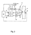
- Fig. 1 to 6 are respectively devices 1 and sections of devices 1 for measuring the fluorescence of a medium 2 with a radiation source 3, an emission receiving element 4 and an optical imaging element 5, wherein the radiation source 3 and the emission receiving element 4 are arranged on the sensor side of the optical imaging element 5 and wherein the radiation source 3, the imaging element 5 and the Emission receiving element 4 are aligned and configured such that the medium present on the medium side of the imaging element 5 with radiation 6 of the radiation source 3 and can be detected by the emission receiving element 4, the emission intensity of the media 2 emitted by fluorescence medium radiation 7.
- the illustrated devices 1 for measuring the fluorescence of a medium 2 are now generally characterized in that a scattering receiving element 8 is arranged and configured on the sensor side of the optical imaging element 5 such that the scattering intensity of the medium radiation 9 scattered by the medium 2 is with the scattering receiving element 8 in the region of the fluorescence of interest due absorption of the radiation 6 of the radiation source 3 can be detected.
- This additional detection of the scattering intensity of the medium radiation 9 scattered by the medium 2 is suitable as an additional quantity for determining the fluorescence of the medium 2, whereby the determination of the fluorescence of the medium 2 with increased accuracy and increased safety is possible.
- a first temperature sensor 30 which detects the temperature of the medium 2, wherein the measurement signal of the temperature sensor 30 is transmitted to the evaluation unit 13 and the measurement of the fluorescence is compensated for the temperature of the medium 2 in the evaluation unit 13.
- the relationship between the fluorescence of the medium 2 and the temperature of the medium 2 is deposited in the evaluation unit 13, so that a compensation of the temperature influence using the current temperature of the medium is possible.
- the temperatures of these receiving elements 4, 8 are also detected with temperature sensors 31, 32 and the evaluation unit 13 made available. In other embodiments, not shown here, the temperature compensation of the receiving elements 4, 8 takes place already in the receiving elements 4, 8 itself, so that already temperature-compensated measuring signals are transmitted to the evaluation unit 13.
- the embodiment according to Fig. 2 comprises a beam splitter 10 between the radiation source 3 and the imaging element 5, the beam splitter 10 directing a known part of the radiation 6 emitted by the radiation source 3, hereinafter referred to as reference radiation 11, to a reference reception element 12, the reference radiation 11 of FIG the reference receiving element 12 can be detected.
- reference radiation 11 the reference radiation 11 of FIG the reference receiving element 12
- the source intensity of the radiation source 3 can also be detected by the reference reception element 12.
- changes in the source intensity of the radiation source 3 -whatever caused- can be taken into account directly in the device 1, either by transferring the source intensity as a separate signal to an external evaluation unit, or be it as in FIGS Fig. 1 to 3 .
- 5 and 6 represented by a corresponding with the detected source intensity of the radiation source 3 signal is transmitted to an internal evaluation unit 13 for calculating the fluorescence of the medium 2.
- the evaluation unit 13 for calculating the fluorescence of the medium 2 in addition to the detected by the emission receiving element 4 emission intensity of the media 2 determined by fluorescence medium radiation 7 and the detected by the scattering receiving element 8 scattering intensity of the medium 2 scattered medium radiation 9 in the region of the fluorescence-related absorption of the radiation 6 of the radiation source 3 transmitted.
- the evaluation unit 13 also receives the source intensity of the radiation source 3 detected by the reference receiving element 12.
- the evaluation unit 13 receives further information, for example about process parameters, which may be significant for the measurement of the fluorescence or the evaluation of the measured fluorescence. However, this is irrelevant to the understanding of the device in question, which is why the provision of the "further information" in the present case is not shown in detail.
- All embodiments shown in the figures are characterized in that the evaluation unit 13, the detected emission intensity of the emitted by fluorescence medium radiation 7 in combination with the other way round in proportion to the emission intensity, the scattered intensity of the medium radiation 9 scattered by the medium 2 in the region of the absorption of the radiation 6 of the radiation source 3 due to the fluorescence of interest is converted into a concentration value of the fluorescent constituents of the medium, which in the exemplary embodiments according to FIGS Fig. 2 and 3 after calibration of the evaluation unit 13 with the source intensity of the radiation source 3 detected by the reference receiving element 12.
- the device 1 according to the Fig. 2 . 3 . 5 and 6 are therefore capable of self-calibration and do not need to be periodically calibrated, for example by evaluating samples.
- the evaluation unit 13 is of course also able to determine the concentration values of other constituents of the medium in which the fluorescent constituents are contained in known proportions.
- the measurement signal also, as previously explained with reference to the temperature sensors 30 to 32, the evaluation unit 13 is transmitted.
- a source-side optical filter 14 is arranged with bandpass characteristic, the source-side optical filter 14 for that frequency range of the radiation 6 of the radiation source 3 is maximally transparent, with the fluorescence of the medium of interest. 2 can be excited. This has the advantage that the medium 2 is excited only very selectively, and naturally there is only a very limited spectrum on the receiving side, which is less annoying and easier to evaluate,
- an optical emission filter 15 with bandpass characteristic wherein the optical emission filter 15 is maximally permeable to the frequency range of the medium radiation 7, in which the interesting, excited by fluorescence radiation 7 of the medium 2 is located.
- an optical scattering filter 16 with bandpass characteristic is arranged, wherein the optical scattering filter 16 is maximally permeable in the frequency range of the medium radiation, in which the medium has 2 due to the fluorescence of interest absorption maximum.
- the source-side optical filter 14 and the diffuse optical filter 16 are designed similarly, since the medium 2 is exposed to electromagnetic radiation of the frequency at which there is an absorption maximum, since the majority of the radiation energy is thereby emitted again due to fluorescence-based emission.
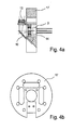
- Fig. 4a shows a first support member 17 in side view, on which the radiation source 3 of the beam splitter 10 and the reference receiving element 12 are arranged together;
- Fig. 4b shows only the first support member 17.
- the source-side optical filter 14 is arranged on the radiation side.
- the beam splitter 10 projects partially into the beam path of the radiation source 3 and directs a known part of the radiation emitted by the radiation source 3, the reference radiation 11, to the reference reception element 12.
- the beam splitter 10 and the reference reception element 12 are aligned such that the reference reception element 12 no return radiation of the medium 2 can be detected.
- the beam splitter 10 is fastened in a recess of the support element 17, wherein the beam splitter is arranged substantially at a 45 ° angle to the main radiation direction of the radiation source 3, so that the main reception direction of the reference reception element 12 and the main emission direction of the radiation source 3 are substantially 90 ° stand on each other.
- the support element 17 is presently formed in one piece and offers the advantage of the modular summary of all those source-side beam-forming elements, on the mutual arrangement of each other matters.
- the radiation source 3 is here formed by an LED (Light Emitting Diode), which emits narrow band, In other, not shown Ausitynmgsbeiari belongs to the radiation source 3, an optical waveguide or a bundle of optical fibers, in which case only the radiating end of the radiation source
- the first support element is arranged and fixed.
- the Fig. 5 and 6 show next to the first support member 17 and a second support member 18 on which the emission receiving element 4 is arranged, wherein on the second support member 18 in addition, the optical emission filter 15 is arranged. Furthermore, the device 1 also has a third support member 19 on which the scatter receiving element 8 is arranged, wherein on the third support member 19 in addition, the optical stray filter 16 is arranged. Further, a fourth support member 20 is provided, in which a recess 21 is provided for unimpeded passage of the radiation of the radiation source 3, wherein around the recess 21 a ring 22 of holding elements is held therein held optical waveguides 23, and the optical waveguides 23 receive the medium radiation and hand off. By forwarding the medium radiation via optical waveguide 23, the emission receiving element 4 and the scattering receiving element 8 can be arranged virtually arbitrarily.
- the four support members 17, 18, 19 and 20 are held in a holding device 24a, 24b and positioned to each other, it is particularly advantageous that the first support member 17 and the fourth support member 20 are fixed together in the holding device 24a, 24b, since the mutual alignment of these support elements 17, 20 is necessary for a suitable and stable alignment of the beam paths.
- the embodiment according to Fig. 6 are all four support members 17 to 20 aligned with each other in the holding device 24a, 24b, so that a total of a very compact design of the device 1 is achieved.
- the evaluation unit 13 can still be seen.
Landscapes
- Health & Medical Sciences (AREA)
- Life Sciences & Earth Sciences (AREA)
- Engineering & Computer Science (AREA)
- Biomedical Technology (AREA)
- Molecular Biology (AREA)
- Nuclear Medicine, Radiotherapy & Molecular Imaging (AREA)
- Physics & Mathematics (AREA)
- Chemical & Material Sciences (AREA)
- Analytical Chemistry (AREA)
- Biochemistry (AREA)
- General Health & Medical Sciences (AREA)
- General Physics & Mathematics (AREA)
- Immunology (AREA)
- Pathology (AREA)
- Investigating, Analyzing Materials By Fluorescence Or Luminescence (AREA)
Applications Claiming Priority (1)
| Application Number | Priority Date | Filing Date | Title |
|---|---|---|---|
| DE200910020252 DE102009020252B4 (de) | 2009-05-07 | 2009-05-07 | Vorrichtung zur Messung der Fluoreszenz eines Mediums |
Publications (2)
| Publication Number | Publication Date |
|---|---|
| EP2249145A2 true EP2249145A2 (fr) | 2010-11-10 |
| EP2249145A3 EP2249145A3 (fr) | 2013-01-09 |
Family
ID=42261844
Family Applications (1)
| Application Number | Title | Priority Date | Filing Date |
|---|---|---|---|
| EP10004738A Withdrawn EP2249145A3 (fr) | 2009-05-07 | 2010-05-05 | dispositif pour mesurer la fluorescence d'un médium |
Country Status (3)
| Country | Link |
|---|---|
| US (1) | US8872133B2 (fr) |
| EP (1) | EP2249145A3 (fr) |
| DE (1) | DE102009020252B4 (fr) |
Cited By (1)
| Publication number | Priority date | Publication date | Assignee | Title |
|---|---|---|---|---|
| WO2014162014A3 (fr) * | 2013-04-06 | 2014-12-04 | Optosphere Spectroscopy Gbr | Dispositif servant à mesurer la dispersion d'un échantillon |
Families Citing this family (12)
| Publication number | Priority date | Publication date | Assignee | Title |
|---|---|---|---|---|
| US8081304B2 (en) | 2006-07-31 | 2011-12-20 | Visualant, Inc. | Method, apparatus, and article to facilitate evaluation of objects using electromagnetic energy |
| MX2012012706A (es) | 2010-05-03 | 2013-04-29 | Goji Ltd | Analisis modal. |
| CN102565016B (zh) * | 2011-12-30 | 2014-05-07 | 北京农业智能装备技术研究中心 | 基于荧光淬灭传感器的检测的温度效应补偿装置及方法 |
| DE102012019433A1 (de) | 2012-10-04 | 2014-04-24 | Krohne Optosens Gmbh | Vorrichtung zur Bestimmung einer Kenngröße eines Mediums |
| US9316581B2 (en) * | 2013-02-04 | 2016-04-19 | Visualant, Inc. | Method, apparatus, and article to facilitate evaluation of substances using electromagnetic energy |
| AT513863B1 (de) * | 2013-02-15 | 2014-12-15 | Vwm Gmbh | Verfahren und Vorrichtung zur Bestimmung einer Konzentration einer fluoreszierenden Substanz in einem Medium |
| US9041920B2 (en) | 2013-02-21 | 2015-05-26 | Visualant, Inc. | Device for evaluation of fluids using electromagnetic energy |
| US9140648B2 (en) * | 2013-03-12 | 2015-09-22 | Ecolab Usa Inc. | Fluorometer with multiple detection channels |
| WO2014165003A1 (fr) | 2013-03-12 | 2014-10-09 | Visualant, Inc. | Systèmes et procédés permettant une analyse de fluide à l'aide de l'énergie électromagnétique |
| US9983184B2 (en) | 2013-09-20 | 2018-05-29 | Reflectonics, Inc. | Using fluorescence measurements for characterizing protein gel-firming processes |
| US9618450B2 (en) * | 2013-09-27 | 2017-04-11 | Ecolab USA, Inc. | Multi-channel fluorometric sensor and method of using same |
| EP3438624A1 (fr) | 2017-08-02 | 2019-02-06 | Senmark Invest Oü | Dispositif et procédé de spectroscopie de fluorescence spectralment réduite |
Family Cites Families (34)
| Publication number | Priority date | Publication date | Assignee | Title |
|---|---|---|---|---|
| US4558014A (en) * | 1983-06-13 | 1985-12-10 | Myron J. Block | Assay apparatus and methods |
| US4750837A (en) * | 1986-04-11 | 1988-06-14 | Sclavo Inc. | Fluorometer with reference light source |
| US20020115122A1 (en) * | 1998-09-10 | 2002-08-22 | Anderson Jeffrey E. | Method and apparatus for automated assessment of the immunoregulatory status of the mononuclear leukocyte immune system |
| US5094819A (en) * | 1989-06-16 | 1992-03-10 | Washington Research Foundation | Fluorescence-based optical sensor and method for detection of lipid-soluble analytes |
| US7328059B2 (en) * | 1996-08-23 | 2008-02-05 | The Texas A & M University System | Imaging of light scattering tissues with fluorescent contrast agents |
| DE19730826A1 (de) * | 1996-11-15 | 1999-01-21 | Optosens Optische Spektroskopi | Kombinierte Absorptions- und Reflektanzspektroskopie zur synchronen Ermittlung der Absorption, Fluoreszenz, Streuung und Brechung transmittierender Flüssigkeiten, Gase und Festkörper |
| US6124937A (en) | 1996-11-15 | 2000-09-26 | Optosens Optische Spektroskopie Und Sensortechnik Gmbh | Method and device for combined absorption and reflectance spectroscopy |
| US6505059B1 (en) * | 1998-04-06 | 2003-01-07 | The General Hospital Corporation | Non-invasive tissue glucose level monitoring |
| US8131053B2 (en) * | 1999-01-25 | 2012-03-06 | Amnis Corporation | Detection of circulating tumor cells using imaging flow cytometry |
| DE19934934C1 (de) * | 1999-05-03 | 2001-06-07 | Optosens Optische Spektroskopi | Verfahren für die gleichzeitige Erfassung von diffuser und specularer Reflexion von Proben, vorzugsweise transparenter Proben, sowie Reflektanz - Meßsonde zur Durchführung des Verfahrens |
| DE10002238A1 (de) * | 1999-05-03 | 2001-07-26 | Optosens Optische Spektroskopi | Reflektanz-Meßsonde |
| GB0125436D0 (en) * | 2001-10-23 | 2001-12-12 | Deltadot Ltd | Analysis of temperature-dependent molecular configurations |
| DE10301931A1 (de) * | 2003-01-19 | 2004-07-29 | Massen, Robert, Prof. Dr.-Ing. | Automatische optische Oberflächeninspektion von farbig gemusterten Oberflächen, welche mit einer transparenten Schutzschicht versehen sind |
| US7151604B2 (en) * | 2004-03-05 | 2006-12-19 | Honeywell International Inc. | Optical system and method for particle detection |
| US7697576B2 (en) * | 2004-05-05 | 2010-04-13 | Chem Image Corporation | Cytological analysis by raman spectroscopic imaging |
| US7319522B2 (en) * | 2004-05-27 | 2008-01-15 | Finesse Solutions Llc. | Systems and methods for in situ spectroscopic measurements |
| US7420679B2 (en) * | 2004-06-30 | 2008-09-02 | Chemimage Corporation | Method and apparatus for extended hyperspectral imaging |
| US7532320B2 (en) * | 2004-06-30 | 2009-05-12 | Chemimage Corporation | Multimodal method for identifying hazardous agents |
| US20060124443A1 (en) * | 2004-11-03 | 2006-06-15 | David Tuschel | Control and monitoring of non-resonant radiation-induced nucleation, crystallization, and polymorph formation |
| JP4954452B2 (ja) * | 2004-07-06 | 2012-06-13 | オリンパス株式会社 | 顕微鏡 |
| CA2575118C (fr) * | 2004-07-27 | 2012-01-03 | Boris Tartakovsky | Systeme fluorometrique a longueurs d'ondes multiples destine a la surveillance en ligne de procedes biologiques |
| JP2006296635A (ja) * | 2005-04-19 | 2006-11-02 | Olympus Corp | 内視鏡装置 |
| EP1918385B1 (fr) * | 2005-07-21 | 2011-06-29 | Morinaga Milk Industry Co., Ltd. | Procédé de détection de micro-organisme et kit de détection de micro-organisme |
| JP4756948B2 (ja) * | 2005-08-08 | 2011-08-24 | ベイバイオサイエンス株式会社 | フローサイトメータおよびフローサイトメトリ方法 |
| US7558619B2 (en) * | 2005-10-04 | 2009-07-07 | Nu Skin International, Inc. | Raman instrument for measuring weak signals in the presence of strong background fluorescence |
| US7596253B2 (en) * | 2005-10-31 | 2009-09-29 | Carestream Health, Inc. | Method and apparatus for detection of caries |
| WO2007056560A2 (fr) * | 2005-11-09 | 2007-05-18 | Chemimage Corporation | Systeme et procede d'analyse cytologique par imagerie spectroscopique raman |
| WO2007067999A2 (fr) * | 2005-12-09 | 2007-06-14 | Amnis Corporation | Systeme d'imagerie a profondeur de champ etendue pour analyse d'objets a grande vitesse |
| US8408269B2 (en) * | 2006-07-28 | 2013-04-02 | Novadaq Technologies, Inc. | System and method for deposition and removal of an optical element on an endoscope objective |
| US20080102473A1 (en) * | 2006-10-31 | 2008-05-01 | Fouquet Julie E | Method and system to improve contrast in lateral flow assay |
| US7923801B2 (en) * | 2007-04-18 | 2011-04-12 | Invisage Technologies, Inc. | Materials, systems and methods for optoelectronic devices |
| US8849380B2 (en) * | 2007-11-26 | 2014-09-30 | Canfield Scientific Inc. | Multi-spectral tissue imaging |
| EP2235736B1 (fr) * | 2007-12-13 | 2015-04-01 | Azbil Corporation | Détection de pathogènes par mesure de taille/fluorescence simultanée |
| US20090236541A1 (en) * | 2008-03-24 | 2009-09-24 | General Electric Company | System and Methods for Optical Imaging |
-
2009
- 2009-05-07 DE DE200910020252 patent/DE102009020252B4/de not_active Expired - Fee Related
-
2010
- 2010-05-05 EP EP10004738A patent/EP2249145A3/fr not_active Withdrawn
- 2010-05-07 US US12/775,855 patent/US8872133B2/en not_active Expired - Fee Related
Non-Patent Citations (1)
| Title |
|---|
| None |
Cited By (2)
| Publication number | Priority date | Publication date | Assignee | Title |
|---|---|---|---|---|
| WO2014162014A3 (fr) * | 2013-04-06 | 2014-12-04 | Optosphere Spectroscopy Gbr | Dispositif servant à mesurer la dispersion d'un échantillon |
| US9952150B2 (en) | 2013-04-06 | 2018-04-24 | L.U.M. Gmbh | Device for measuring the scattering of a sample |
Also Published As
| Publication number | Publication date |
|---|---|
| US20100282982A1 (en) | 2010-11-11 |
| EP2249145A3 (fr) | 2013-01-09 |
| DE102009020252B4 (de) | 2012-01-12 |
| DE102009020252A1 (de) | 2010-11-11 |
| US8872133B2 (en) | 2014-10-28 |
Similar Documents
| Publication | Publication Date | Title |
|---|---|---|
| DE102009020252B4 (de) | Vorrichtung zur Messung der Fluoreszenz eines Mediums | |
| EP2003441B1 (fr) | Capteur ATR | |
| DE69835142T2 (de) | VORRICHTUNG zur Bestimmung VON STÖRENDEN SUBSTANZEN im PLASMA | |
| DE69032442T2 (de) | Verfahren zur Kennzeichnung eines Materials biologischer Herkunft, unter Verwendung der Nah-Infrarotspektroskopie | |
| DE102004048103B4 (de) | Spektrometrischer Messkopf für Erntemaschinen und andere landwirtschaftlich genutzte Maschinen | |
| EP1965193A1 (fr) | Procédé de détermination de la teneur en alcool de liquides | |
| EP2246692B1 (fr) | Procédé de détection d'impuretés d'une cuvette de mesure optique | |
| AT510765B1 (de) | Vorrichtung zur photometrischen bzw. spektrometrischen untersuchung einer flüssigen probe | |
| DE69222287T2 (de) | Verfahren und Gerät zur Messung des Inhalts an in einer flüssigen organischen Phase aufgelöstem Wasser | |
| EP2726847A1 (fr) | Dispositif comprenant un système de mesure optique de gaz et de mélanges gazeux compensant les influences de l'environnement | |
| DE102017114317A1 (de) | Spektrometrisches Messgerät | |
| DE112020003132T5 (de) | Mehrkanalgassensor | |
| EP0472899B1 (fr) | Dispositif de mesure photométrique | |
| EP3270045B1 (fr) | Systeme de mesure de concentrations de gaz | |
| DE3938142C2 (fr) | ||
| DE102021100321B4 (de) | SPR-Sensoreinheit und Verfahren zur Bestimmung des Brechungsindex eines Proben-mediums sowie Messeinrichtung zur Erfassung der Dichte eines Messmediums | |
| DE19626203A1 (de) | Optischer Sensor | |
| DE60122332T2 (de) | Nicht-dispersive infrarot messung von gasen mit einem optischen filter | |
| DE202022000633U1 (de) | Vorrichtung zur spektroskopischen Bestimmung von Analyten mit variabler druckabhängiger Empfindlichkeit | |
| EP2981809B1 (fr) | Dispositif servant à mesurer la dispersion d'un échantillon | |
| WO2023036651A1 (fr) | Photomètre raman pour analyse simultanée de composants multiples ; système de mesure et produit programme d'ordinateur | |
| DE102022130055A1 (de) | Vorrichtung, Haushaltsgerät und Verfahren zur Partikelgrößenbestimmung | |
| DE19848120C2 (de) | Einrichtung zur Messung der Strahlungsabsorption von Gasen | |
| EP1929279B1 (fr) | Procede et dispositif pour determiner l'indice de refraction d'un fluide | |
| DE102019104556A1 (de) | Verfahren sowie eine Vorrichtung zur Bestimmung optischer Eigenschaften eines Probenmaterials |
Legal Events
| Date | Code | Title | Description |
|---|---|---|---|
| PUAI | Public reference made under article 153(3) epc to a published international application that has entered the european phase |
Free format text: ORIGINAL CODE: 0009012 |
|
| AK | Designated contracting states |
Kind code of ref document: A2 Designated state(s): AL AT BE BG CH CY CZ DE DK EE ES FI FR GB GR HR HU IE IS IT LI LT LU LV MC MK MT NL NO PL PT RO SE SI SK SM TR |
|
| AX | Request for extension of the european patent |
Extension state: BA ME RS |
|
| RIN1 | Information on inventor provided before grant (corrected) |
Inventor name: FRITSCH, THOMAS, DR. Inventor name: SCHREIBER, MARCO, DR. |
|
| PUAL | Search report despatched |
Free format text: ORIGINAL CODE: 0009013 |
|
| AK | Designated contracting states |
Kind code of ref document: A3 Designated state(s): AL AT BE BG CH CY CZ DE DK EE ES FI FR GB GR HR HU IE IS IT LI LT LU LV MC MK MT NL NO PL PT RO SE SI SK SM TR |
|
| AX | Request for extension of the european patent |
Extension state: BA ME RS |
|
| RIC1 | Information provided on ipc code assigned before grant |
Ipc: G01N 21/64 20060101AFI20121130BHEP Ipc: G01N 21/85 20060101ALI20121130BHEP |
|
| 17P | Request for examination filed |
Effective date: 20131018 |
|
| RBV | Designated contracting states (corrected) |
Designated state(s): AL AT BE BG CH CY CZ DE DK EE ES FI FR GB GR HR HU IE IS IT LI LT LU LV MC MK MT NL NO PL PT RO SE SI SK SM TR |
|
| STAA | Information on the status of an ep patent application or granted ep patent |
Free format text: STATUS: THE APPLICATION HAS BEEN WITHDRAWN |
|
| 18W | Application withdrawn |
Effective date: 20170307 |