EP2249016A1 - Vorrichtung und verfahren zur fahrzeugsteuerung - Google Patents
Vorrichtung und verfahren zur fahrzeugsteuerung Download PDFInfo
- Publication number
- EP2249016A1 EP2249016A1 EP09717444A EP09717444A EP2249016A1 EP 2249016 A1 EP2249016 A1 EP 2249016A1 EP 09717444 A EP09717444 A EP 09717444A EP 09717444 A EP09717444 A EP 09717444A EP 2249016 A1 EP2249016 A1 EP 2249016A1
- Authority
- EP
- European Patent Office
- Prior art keywords
- operation line
- internal combustion
- combustion engine
- amount
- reducing agent
- Prior art date
- Legal status (The legal status is an assumption and is not a legal conclusion. Google has not performed a legal analysis and makes no representation as to the accuracy of the status listed.)
- Granted
Links
Images



Classifications
-
- B—PERFORMING OPERATIONS; TRANSPORTING
- B60—VEHICLES IN GENERAL
- B60W—CONJOINT CONTROL OF VEHICLE SUB-UNITS OF DIFFERENT TYPE OR DIFFERENT FUNCTION; CONTROL SYSTEMS SPECIALLY ADAPTED FOR HYBRID VEHICLES; ROAD VEHICLE DRIVE CONTROL SYSTEMS FOR PURPOSES NOT RELATED TO THE CONTROL OF A PARTICULAR SUB-UNIT
- B60W20/00—Control systems specially adapted for hybrid vehicles
- B60W20/10—Controlling the power contribution of each of the prime movers to meet required power demand
- B60W20/15—Control strategies specially adapted for achieving a particular effect
-
- B—PERFORMING OPERATIONS; TRANSPORTING
- B60—VEHICLES IN GENERAL
- B60K—ARRANGEMENT OR MOUNTING OF PROPULSION UNITS OR OF TRANSMISSIONS IN VEHICLES; ARRANGEMENT OR MOUNTING OF PLURAL DIVERSE PRIME-MOVERS IN VEHICLES; AUXILIARY DRIVES FOR VEHICLES; INSTRUMENTATION OR DASHBOARDS FOR VEHICLES; ARRANGEMENTS IN CONNECTION WITH COOLING, AIR INTAKE, GAS EXHAUST OR FUEL SUPPLY OF PROPULSION UNITS IN VEHICLES
- B60K6/00—Arrangement or mounting of plural diverse prime-movers for mutual or common propulsion, e.g. hybrid propulsion systems comprising electric motors and internal combustion engines
- B60K6/20—Arrangement or mounting of plural diverse prime-movers for mutual or common propulsion, e.g. hybrid propulsion systems comprising electric motors and internal combustion engines the prime-movers consisting of electric motors and internal combustion engines, e.g. HEVs
- B60K6/22—Arrangement or mounting of plural diverse prime-movers for mutual or common propulsion, e.g. hybrid propulsion systems comprising electric motors and internal combustion engines the prime-movers consisting of electric motors and internal combustion engines, e.g. HEVs characterised by apparatus, components or means specially adapted for HEVs
- B60K6/36—Arrangement or mounting of plural diverse prime-movers for mutual or common propulsion, e.g. hybrid propulsion systems comprising electric motors and internal combustion engines the prime-movers consisting of electric motors and internal combustion engines, e.g. HEVs characterised by apparatus, components or means specially adapted for HEVs characterised by the transmission gearings
- B60K6/365—Arrangement or mounting of plural diverse prime-movers for mutual or common propulsion, e.g. hybrid propulsion systems comprising electric motors and internal combustion engines the prime-movers consisting of electric motors and internal combustion engines, e.g. HEVs characterised by apparatus, components or means specially adapted for HEVs characterised by the transmission gearings with the gears having orbital motion
-
- B—PERFORMING OPERATIONS; TRANSPORTING
- B60—VEHICLES IN GENERAL
- B60K—ARRANGEMENT OR MOUNTING OF PROPULSION UNITS OR OF TRANSMISSIONS IN VEHICLES; ARRANGEMENT OR MOUNTING OF PLURAL DIVERSE PRIME-MOVERS IN VEHICLES; AUXILIARY DRIVES FOR VEHICLES; INSTRUMENTATION OR DASHBOARDS FOR VEHICLES; ARRANGEMENTS IN CONNECTION WITH COOLING, AIR INTAKE, GAS EXHAUST OR FUEL SUPPLY OF PROPULSION UNITS IN VEHICLES
- B60K6/00—Arrangement or mounting of plural diverse prime-movers for mutual or common propulsion, e.g. hybrid propulsion systems comprising electric motors and internal combustion engines
- B60K6/20—Arrangement or mounting of plural diverse prime-movers for mutual or common propulsion, e.g. hybrid propulsion systems comprising electric motors and internal combustion engines the prime-movers consisting of electric motors and internal combustion engines, e.g. HEVs
- B60K6/42—Arrangement or mounting of plural diverse prime-movers for mutual or common propulsion, e.g. hybrid propulsion systems comprising electric motors and internal combustion engines the prime-movers consisting of electric motors and internal combustion engines, e.g. HEVs characterised by the architecture of the hybrid electric vehicle
- B60K6/44—Series-parallel type
- B60K6/445—Differential gearing distribution type
-
- B—PERFORMING OPERATIONS; TRANSPORTING
- B60—VEHICLES IN GENERAL
- B60W—CONJOINT CONTROL OF VEHICLE SUB-UNITS OF DIFFERENT TYPE OR DIFFERENT FUNCTION; CONTROL SYSTEMS SPECIALLY ADAPTED FOR HYBRID VEHICLES; ROAD VEHICLE DRIVE CONTROL SYSTEMS FOR PURPOSES NOT RELATED TO THE CONTROL OF A PARTICULAR SUB-UNIT
- B60W10/00—Conjoint control of vehicle sub-units of different type or different function
- B60W10/04—Conjoint control of vehicle sub-units of different type or different function including control of propulsion units
- B60W10/06—Conjoint control of vehicle sub-units of different type or different function including control of propulsion units including control of combustion engines
-
- F—MECHANICAL ENGINEERING; LIGHTING; HEATING; WEAPONS; BLASTING
- F01—MACHINES OR ENGINES IN GENERAL; ENGINE PLANTS IN GENERAL; STEAM ENGINES
- F01N—GAS-FLOW SILENCERS OR EXHAUST APPARATUS FOR MACHINES OR ENGINES IN GENERAL; GAS-FLOW SILENCERS OR EXHAUST APPARATUS FOR INTERNAL-COMBUSTION ENGINES
- F01N11/00—Monitoring or diagnostic devices for exhaust-gas treatment apparatus
-
- F—MECHANICAL ENGINEERING; LIGHTING; HEATING; WEAPONS; BLASTING
- F02—COMBUSTION ENGINES; HOT-GAS OR COMBUSTION-PRODUCT ENGINE PLANTS
- F02D—CONTROLLING COMBUSTION ENGINES
- F02D29/00—Controlling engines, such controlling being peculiar to the devices driven thereby, the devices being other than parts or accessories essential to engine operation, e.g. controlling of engines by signals external thereto
- F02D29/02—Controlling engines, such controlling being peculiar to the devices driven thereby, the devices being other than parts or accessories essential to engine operation, e.g. controlling of engines by signals external thereto peculiar to engines driving vehicles; peculiar to engines driving variable pitch propellers
-
- F—MECHANICAL ENGINEERING; LIGHTING; HEATING; WEAPONS; BLASTING
- F02—COMBUSTION ENGINES; HOT-GAS OR COMBUSTION-PRODUCT ENGINE PLANTS
- F02D—CONTROLLING COMBUSTION ENGINES
- F02D41/00—Electrical control of supply of combustible mixture or its constituents
- F02D41/02—Circuit arrangements for generating control signals
- F02D41/021—Introducing corrections for particular conditions exterior to the engine
- F02D41/0215—Introducing corrections for particular conditions exterior to the engine in relation with elements of the transmission
- F02D41/023—Introducing corrections for particular conditions exterior to the engine in relation with elements of the transmission in relation with the gear ratio shifting
-
- F—MECHANICAL ENGINEERING; LIGHTING; HEATING; WEAPONS; BLASTING
- F02—COMBUSTION ENGINES; HOT-GAS OR COMBUSTION-PRODUCT ENGINE PLANTS
- F02D—CONTROLLING COMBUSTION ENGINES
- F02D41/00—Electrical control of supply of combustible mixture or its constituents
- F02D41/02—Circuit arrangements for generating control signals
- F02D41/021—Introducing corrections for particular conditions exterior to the engine
- F02D41/0235—Introducing corrections for particular conditions exterior to the engine in relation with the state of the exhaust gas treating apparatus
-
- B—PERFORMING OPERATIONS; TRANSPORTING
- B60—VEHICLES IN GENERAL
- B60K—ARRANGEMENT OR MOUNTING OF PROPULSION UNITS OR OF TRANSMISSIONS IN VEHICLES; ARRANGEMENT OR MOUNTING OF PLURAL DIVERSE PRIME-MOVERS IN VEHICLES; AUXILIARY DRIVES FOR VEHICLES; INSTRUMENTATION OR DASHBOARDS FOR VEHICLES; ARRANGEMENTS IN CONNECTION WITH COOLING, AIR INTAKE, GAS EXHAUST OR FUEL SUPPLY OF PROPULSION UNITS IN VEHICLES
- B60K1/00—Arrangement or mounting of electrical propulsion units
- B60K1/02—Arrangement or mounting of electrical propulsion units comprising more than one electric motor
-
- B—PERFORMING OPERATIONS; TRANSPORTING
- B60—VEHICLES IN GENERAL
- B60L—PROPULSION OF ELECTRICALLY-PROPELLED VEHICLES; SUPPLYING ELECTRIC POWER FOR AUXILIARY EQUIPMENT OF ELECTRICALLY-PROPELLED VEHICLES; ELECTRODYNAMIC BRAKE SYSTEMS FOR VEHICLES IN GENERAL; MAGNETIC SUSPENSION OR LEVITATION FOR VEHICLES; MONITORING OPERATING VARIABLES OF ELECTRICALLY-PROPELLED VEHICLES; ELECTRIC SAFETY DEVICES FOR ELECTRICALLY-PROPELLED VEHICLES
- B60L2240/00—Control parameters of input or output; Target parameters
- B60L2240/40—Drive Train control parameters
- B60L2240/44—Drive Train control parameters related to combustion engines
- B60L2240/445—Temperature
-
- B—PERFORMING OPERATIONS; TRANSPORTING
- B60—VEHICLES IN GENERAL
- B60W—CONJOINT CONTROL OF VEHICLE SUB-UNITS OF DIFFERENT TYPE OR DIFFERENT FUNCTION; CONTROL SYSTEMS SPECIALLY ADAPTED FOR HYBRID VEHICLES; ROAD VEHICLE DRIVE CONTROL SYSTEMS FOR PURPOSES NOT RELATED TO THE CONTROL OF A PARTICULAR SUB-UNIT
- B60W20/00—Control systems specially adapted for hybrid vehicles
-
- B—PERFORMING OPERATIONS; TRANSPORTING
- B60—VEHICLES IN GENERAL
- B60W—CONJOINT CONTROL OF VEHICLE SUB-UNITS OF DIFFERENT TYPE OR DIFFERENT FUNCTION; CONTROL SYSTEMS SPECIALLY ADAPTED FOR HYBRID VEHICLES; ROAD VEHICLE DRIVE CONTROL SYSTEMS FOR PURPOSES NOT RELATED TO THE CONTROL OF A PARTICULAR SUB-UNIT
- B60W2510/00—Input parameters relating to a particular sub-units
- B60W2510/06—Combustion engines, Gas turbines
- B60W2510/0676—Engine temperature
-
- B—PERFORMING OPERATIONS; TRANSPORTING
- B60—VEHICLES IN GENERAL
- B60W—CONJOINT CONTROL OF VEHICLE SUB-UNITS OF DIFFERENT TYPE OR DIFFERENT FUNCTION; CONTROL SYSTEMS SPECIALLY ADAPTED FOR HYBRID VEHICLES; ROAD VEHICLE DRIVE CONTROL SYSTEMS FOR PURPOSES NOT RELATED TO THE CONTROL OF A PARTICULAR SUB-UNIT
- B60W2510/00—Input parameters relating to a particular sub-units
- B60W2510/06—Combustion engines, Gas turbines
- B60W2510/068—Engine exhaust temperature
-
- B—PERFORMING OPERATIONS; TRANSPORTING
- B60—VEHICLES IN GENERAL
- B60W—CONJOINT CONTROL OF VEHICLE SUB-UNITS OF DIFFERENT TYPE OR DIFFERENT FUNCTION; CONTROL SYSTEMS SPECIALLY ADAPTED FOR HYBRID VEHICLES; ROAD VEHICLE DRIVE CONTROL SYSTEMS FOR PURPOSES NOT RELATED TO THE CONTROL OF A PARTICULAR SUB-UNIT
- B60W2510/00—Input parameters relating to a particular sub-units
- B60W2510/06—Combustion engines, Gas turbines
- B60W2510/0685—Engine crank angle
-
- B—PERFORMING OPERATIONS; TRANSPORTING
- B60—VEHICLES IN GENERAL
- B60W—CONJOINT CONTROL OF VEHICLE SUB-UNITS OF DIFFERENT TYPE OR DIFFERENT FUNCTION; CONTROL SYSTEMS SPECIALLY ADAPTED FOR HYBRID VEHICLES; ROAD VEHICLE DRIVE CONTROL SYSTEMS FOR PURPOSES NOT RELATED TO THE CONTROL OF A PARTICULAR SUB-UNIT
- B60W2510/00—Input parameters relating to a particular sub-units
- B60W2510/24—Energy storage means
- B60W2510/242—Energy storage means for electrical energy
- B60W2510/244—Charge state
-
- B—PERFORMING OPERATIONS; TRANSPORTING
- B60—VEHICLES IN GENERAL
- B60W—CONJOINT CONTROL OF VEHICLE SUB-UNITS OF DIFFERENT TYPE OR DIFFERENT FUNCTION; CONTROL SYSTEMS SPECIALLY ADAPTED FOR HYBRID VEHICLES; ROAD VEHICLE DRIVE CONTROL SYSTEMS FOR PURPOSES NOT RELATED TO THE CONTROL OF A PARTICULAR SUB-UNIT
- B60W2520/00—Input parameters relating to overall vehicle dynamics
- B60W2520/10—Longitudinal speed
-
- B—PERFORMING OPERATIONS; TRANSPORTING
- B60—VEHICLES IN GENERAL
- B60W—CONJOINT CONTROL OF VEHICLE SUB-UNITS OF DIFFERENT TYPE OR DIFFERENT FUNCTION; CONTROL SYSTEMS SPECIALLY ADAPTED FOR HYBRID VEHICLES; ROAD VEHICLE DRIVE CONTROL SYSTEMS FOR PURPOSES NOT RELATED TO THE CONTROL OF A PARTICULAR SUB-UNIT
- B60W2540/00—Input parameters relating to occupants
- B60W2540/10—Accelerator pedal position
-
- B—PERFORMING OPERATIONS; TRANSPORTING
- B60—VEHICLES IN GENERAL
- B60W—CONJOINT CONTROL OF VEHICLE SUB-UNITS OF DIFFERENT TYPE OR DIFFERENT FUNCTION; CONTROL SYSTEMS SPECIALLY ADAPTED FOR HYBRID VEHICLES; ROAD VEHICLE DRIVE CONTROL SYSTEMS FOR PURPOSES NOT RELATED TO THE CONTROL OF A PARTICULAR SUB-UNIT
- B60W2710/00—Output or target parameters relating to a particular sub-units
- B60W2710/06—Combustion engines, Gas turbines
- B60W2710/0616—Position of fuel or air injector
-
- F—MECHANICAL ENGINEERING; LIGHTING; HEATING; WEAPONS; BLASTING
- F01—MACHINES OR ENGINES IN GENERAL; ENGINE PLANTS IN GENERAL; STEAM ENGINES
- F01N—GAS-FLOW SILENCERS OR EXHAUST APPARATUS FOR MACHINES OR ENGINES IN GENERAL; GAS-FLOW SILENCERS OR EXHAUST APPARATUS FOR INTERNAL-COMBUSTION ENGINES
- F01N2550/00—Monitoring or diagnosing the deterioration of exhaust systems
- F01N2550/05—Systems for adding substances into exhaust
-
- F—MECHANICAL ENGINEERING; LIGHTING; HEATING; WEAPONS; BLASTING
- F01—MACHINES OR ENGINES IN GENERAL; ENGINE PLANTS IN GENERAL; STEAM ENGINES
- F01N—GAS-FLOW SILENCERS OR EXHAUST APPARATUS FOR MACHINES OR ENGINES IN GENERAL; GAS-FLOW SILENCERS OR EXHAUST APPARATUS FOR INTERNAL-COMBUSTION ENGINES
- F01N2900/00—Details of electrical control or of the monitoring of the exhaust gas treating apparatus
- F01N2900/06—Parameters used for exhaust control or diagnosing
- F01N2900/18—Parameters used for exhaust control or diagnosing said parameters being related to the system for adding a substance into the exhaust
- F01N2900/1806—Properties of reducing agent or dosing system
- F01N2900/1814—Tank level
-
- F—MECHANICAL ENGINEERING; LIGHTING; HEATING; WEAPONS; BLASTING
- F01—MACHINES OR ENGINES IN GENERAL; ENGINE PLANTS IN GENERAL; STEAM ENGINES
- F01N—GAS-FLOW SILENCERS OR EXHAUST APPARATUS FOR MACHINES OR ENGINES IN GENERAL; GAS-FLOW SILENCERS OR EXHAUST APPARATUS FOR INTERNAL-COMBUSTION ENGINES
- F01N3/00—Exhaust or silencing apparatus having means for purifying, rendering innocuous, or otherwise treating exhaust
- F01N3/08—Exhaust or silencing apparatus having means for purifying, rendering innocuous, or otherwise treating exhaust for rendering innocuous
- F01N3/10—Exhaust or silencing apparatus having means for purifying, rendering innocuous, or otherwise treating exhaust for rendering innocuous by thermal or catalytic conversion of noxious components of exhaust
- F01N3/18—Exhaust or silencing apparatus having means for purifying, rendering innocuous, or otherwise treating exhaust for rendering innocuous by thermal or catalytic conversion of noxious components of exhaust characterised by methods of operation; Control
- F01N3/20—Exhaust or silencing apparatus having means for purifying, rendering innocuous, or otherwise treating exhaust for rendering innocuous by thermal or catalytic conversion of noxious components of exhaust characterised by methods of operation; Control specially adapted for catalytic conversion
- F01N3/206—Adding periodically or continuously substances to exhaust gases for promoting purification, e.g. catalytic material in liquid form, NOx reducing agents
- F01N3/2066—Selective catalytic reduction [SCR]
-
- F—MECHANICAL ENGINEERING; LIGHTING; HEATING; WEAPONS; BLASTING
- F02—COMBUSTION ENGINES; HOT-GAS OR COMBUSTION-PRODUCT ENGINE PLANTS
- F02D—CONTROLLING COMBUSTION ENGINES
- F02D2250/00—Engine control related to specific problems or objectives
- F02D2250/36—Control for minimising NOx emissions
-
- F—MECHANICAL ENGINEERING; LIGHTING; HEATING; WEAPONS; BLASTING
- F02—COMBUSTION ENGINES; HOT-GAS OR COMBUSTION-PRODUCT ENGINE PLANTS
- F02N—STARTING OF COMBUSTION ENGINES; STARTING AIDS FOR SUCH ENGINES, NOT OTHERWISE PROVIDED FOR
- F02N11/00—Starting of engines by means of electric motors
- F02N11/04—Starting of engines by means of electric motors the motors being associated with current generators
-
- Y—GENERAL TAGGING OF NEW TECHNOLOGICAL DEVELOPMENTS; GENERAL TAGGING OF CROSS-SECTIONAL TECHNOLOGIES SPANNING OVER SEVERAL SECTIONS OF THE IPC; TECHNICAL SUBJECTS COVERED BY FORMER USPC CROSS-REFERENCE ART COLLECTIONS [XRACs] AND DIGESTS
- Y02—TECHNOLOGIES OR APPLICATIONS FOR MITIGATION OR ADAPTATION AGAINST CLIMATE CHANGE
- Y02A—TECHNOLOGIES FOR ADAPTATION TO CLIMATE CHANGE
- Y02A50/00—TECHNOLOGIES FOR ADAPTATION TO CLIMATE CHANGE in human health protection, e.g. against extreme weather
- Y02A50/20—Air quality improvement or preservation, e.g. vehicle emission control or emission reduction by using catalytic converters
-
- Y—GENERAL TAGGING OF NEW TECHNOLOGICAL DEVELOPMENTS; GENERAL TAGGING OF CROSS-SECTIONAL TECHNOLOGIES SPANNING OVER SEVERAL SECTIONS OF THE IPC; TECHNICAL SUBJECTS COVERED BY FORMER USPC CROSS-REFERENCE ART COLLECTIONS [XRACs] AND DIGESTS
- Y02—TECHNOLOGIES OR APPLICATIONS FOR MITIGATION OR ADAPTATION AGAINST CLIMATE CHANGE
- Y02T—CLIMATE CHANGE MITIGATION TECHNOLOGIES RELATED TO TRANSPORTATION
- Y02T10/00—Road transport of goods or passengers
- Y02T10/10—Internal combustion engine [ICE] based vehicles
- Y02T10/40—Engine management systems
-
- Y—GENERAL TAGGING OF NEW TECHNOLOGICAL DEVELOPMENTS; GENERAL TAGGING OF CROSS-SECTIONAL TECHNOLOGIES SPANNING OVER SEVERAL SECTIONS OF THE IPC; TECHNICAL SUBJECTS COVERED BY FORMER USPC CROSS-REFERENCE ART COLLECTIONS [XRACs] AND DIGESTS
- Y02—TECHNOLOGIES OR APPLICATIONS FOR MITIGATION OR ADAPTATION AGAINST CLIMATE CHANGE
- Y02T—CLIMATE CHANGE MITIGATION TECHNOLOGIES RELATED TO TRANSPORTATION
- Y02T10/00—Road transport of goods or passengers
- Y02T10/60—Other road transportation technologies with climate change mitigation effect
- Y02T10/62—Hybrid vehicles
Definitions
- the present invention relates to a control device for a vehicle equipped with an internal combustion engine, and to a technique of changing an operation line of the internal combustion engine in accordance with a reserved amount of a reducing agent to be supplied to an exhaust path.
- an SCR (Selective Catalytic Reduction) device has been known as a device for purifying nitrogen oxide (hereinafter described as NOx) in exhaust gas emitted from an engine.
- NOx nitrogen oxide
- the SCR device injects a reducing agent (for example, ammonia or the like) to an exhaust path of the engine to make NOx in the exhaust gas and the reducing agent to react on a catalyst, thereby reducing and purifying NOx.
- a reducing agent for example, ammonia or the like
- Patent Document 1 discloses an exhaust gas purification device for an engine that urges a driver to have an SCR device repaired immediately when an abnormality occurs in the SCR device and provides appropriate management of the SCR device.
- the exhaust gas purification device for an engine includes reducing agent addition means adding a reducing agent for NOx to exhaust gas from the engine, abnormality detection means detecting occurrence of an abnormality in the reducing agent addition means, and engine control means providing control, when occurrence of an abnormality is detected by the abnormality detection means, to limit operation of the engine, or to set output characteristics of the engine with respect to accelerator operation by the driver to be different from those in normal operation other than operation at the time of occurrence of an abnormality.
- the exhaust gas purification device for an engine when an addition device has an abnormality and cannot add an appropriate amount of the reducing agent to the exhaust gas, operation of the engine is limited, for example, restart of the engine that has been once stopped is disabled. Thereby, traveling in a state where NOx is not sufficiently purified can be limited, and the driver can be urged to have the addition device repaired. Further, in addition to or instead of limiting operation of the engine, by changing the output characteristics of the engine with respect to the accelerator operation, for example, by decreasing a fuel injection amount set for the same amount of accelerator operation to be smaller than that in normal operation, traveling can be limited and the driver can be urged to have the addition device repaired.
- a control device for a vehicle in accordance with an aspect of the present invention is a control device for a vehicle equipped with an internal combustion engine.
- the internal combustion engine includes an exhaust path, an injection device injecting a reducing agent to the exhaust path, and a reserving unit reserving the reducing agent.
- the control device includes a reserved amount detection unit detecting a reserved amount of the reducing agent in the reserving unit, and a control unit receiving an output from the reserved amount detection unit.
- the control unit changes an operation line of the internal combustion engine to an operation line with a lower degree of generation of nitrogen oxide step by step in accordance with a decrease in the detected reserved amount, and controls an output of the internal combustion engine based on the changed operation line.
- an operation line of the internal combustion engine is changed to an operation line on a side with a lower NOx concentration step by step in accordance with a decrease in the reserved amount of the reducing agent.
- the operation line changed in accordance with the decrease in the reserved amount is an operation line with a lower degree of generation of torque with respect to a rotation speed of the internal combustion engine, when compared with the operation line before change.
- the operation line of the internal combustion engine is changed to an operation line with a lower degree of generation of torque with respect to a rotation speed of the internal combustion engine, among a plurality of predetermined operation lines.
- the operation line of the internal combustion engine is changed to an operation line with a lower degree of generation of NOx, an increase in the NOx concentration can be suppressed.
- the operation line of the internal combustion engine is set corresponding to a case where the reserved amount of the reducing agent in the reserving unit is equal to or more than a predetermined amount, and includes at least a first operation line as an optimum fuel efficiency operation line of the internal combustion engine, a second operation line set corresponding to a case where the reserved amount of the reducing agent in the reserving unit is zero, and a third operation line set between the first operation line and the second operation line.
- the control unit changes the operation line of the internal combustion engine to an operation line corresponding to the detected reserved amount among the first operation line, the second operation line, and the third operation line.
- the output of the internal combustion engine is controlled along the optimum fuel efficiency line of the internal combustion engine.
- the internal combustion engine can be operated with the NOx concentration in the exhaust gas being decreased by injecting the reducing agent and with deterioration of fuel efficiency of the internal combustion engine being suppressed.
- the output of the internal combustion engine is controlled along an operation line set corresponding to the case where the reserved amount is zero.
- the degree of generation of NOx can be decreased, and an increase in the NOx concentration in the exhaust gas can be suppressed.
- the operation line is changed step by step from the first operation line to the second operation line via the third operation line, in accordance with a decrease in the reserved amount. This suppresses the driver from feeling that the vehicle's behavior suddenly becomes not normal.
- control unit controls the output of the internal combustion engine by changing an operation point along an equal output line in accordance with change of the operation line.
- the output of the internal combustion engine is controlled by changing an operation point along an equal output line in accordance with change of the operation line.
- the internal combustion engine can be operated without limiting the output thereof.
- control device further includes a traveling distance detection unit detecting a physical quantity related to a traveling distance of the vehicle, an injection amount calculation unit calculating an injection amount of fuel injected to the internal combustion engine, a deterioration degree calculation unit calculating a degree of deterioration of fuel efficiency of the internal combustion engine based on the detected physical quantity and a supply amount of the fuel, and a fuel efficiency informing unit informing a driver of the calculated degree of deterioration of fuel efficiency.
- the present invention when the operation line is changed to an operation line with a lower degree of generation of the NOx concentration due to a decrease in the reserved amount of the reducing agent, fuel efficiency of the internal combustion engine is deteriorated. Therefore, by informing the driver of the degree of deterioration of fuel efficiency, the driver can recognize that the fuel efficiency is worse than usual. That is, the driver can be urged to replenish the reducing agent. Consequently, a control device and a control method for a vehicle appropriately informing a driver of presence or absence of a reducing agent can be provided.
- control device further includes a solution amount informing unit informing the driver of the detected reserved amount.
- the driver by informing the driver of a decrease in the reserved amount of the reducing agent, the driver can be urged to replenish the reducing agent. Consequently, the driver can be appropriately informed of presence or absence of the reducing agent.
- the internal combustion engine is a lean burn gasoline engine.
- an increase in the NOx concentration can be suppressed while avoiding the driver from feeling that the vehicle suddenly falls into a state that is not normal by changing the operation line step by step.
- the internal combustion engine is a diesel engine.
- an increase in the NOx concentration can be suppressed while avoiding the driver from feeling that the vehicle suddenly becomes not normal by changing the operation line step by step.
- the vehicle is a hybrid vehicle having the internal combustion engine and a rotating electric machine as drive sources.
- an increase in the NOx concentration can be suppressed while avoiding the driver from feeling that the vehicle suddenly becomes not normal by changing the operation line step by step without limiting the output of the internal combustion engine.
- the vehicle is a vehicle equipped with a continuously variable transmission continuously changing a gear ratio.
- an increase in the NOx concentration can be suppressed while avoiding the driver from feeling that the vehicle suddenly becomes not normal by changing the operation line step by step without limiting the output of the internal combustion engine.
- 120 engine, 122: intake path, 122A: air cleaner, 122B: air flow meter, 122C: electronic throttle valve, 122D: throttle position sensor, 124: exhaust path, 124A: air-fuel ratio sensor, 124B: three-way catalytic converter, 124C: catalyst temperature sensor, 124D: silencer, 130: fuel injection device, 140A, 140B: motor generator, 160: drive wheels, 180: reduction gear, 200: motive power split mechanism, 220: traveling battery, 240: inverter, 242: converter, 300: input I/F, 312: aqueous urea solution amount sensor, 314: aqueous urea solution injection device, 316: aqueous urea solution tank, 318: accelerator position sensor, 330: vehicle speed sensor, 340: display device, 342: solution amount indicator, 344: fuel efficiency indicator, 360: water temperature detection sensor, 380: crank position sensor, 400: computation processing unit, 402: solution amount determination unit, 404: operation line setting unit, 406
- FIG. 1 a control block diagram of a hybrid vehicle to which a control device in accordance with an embodiment of the present invention is applied will be described.
- the hybrid vehicle includes, as drive sources, an internal combustion engine (hereinafter simply referred to as an engine) 120 that requires NOx purification such as a lean burn gasoline engine or a diesel engine, and a motor generator (hereinafter simply referred to as an MG) (1) 140A and MG(2) 140B serving as rotating electric machines.
- an engine 120 that requires NOx purification
- a motor generator hereinafter simply referred to as an MG
- MG motor generator
- An intake path 122 of engine 120 is provided with an air cleaner 122A catching dust in intake air, an air flow meter 122B detecting an amount of air passing through air cleaner 122A to be taken into engine 120, and an electronic throttle valve 122C as a valve for adjusting the amount of air to be taken into engine 120.
- Electronic throttle valve 122C is provided with a throttle position sensor 122D. The amount of intake air detected by air flow meter 122B, an opening degree of electronic throttle valve 122C detected by throttle position sensor 122D, and the like are input to an ECU (Electronic Control Unit) 320.
- ECU Electronic Control Unit
- Engine 120 is provided with a plurality of cylinders and a fuel injection device 130 injecting fuel to each cylinder.
- Fuel injection device 130 injects an appropriate amount of fuel to each cylinder at an appropriate time based on a fuel injection control signal from ECU 320.
- an exhaust path 124 of engine 120 is provided with a three-way catalytic converter 124B, an air-fuel ratio sensor 124A detecting an air-fuel ratio (A/F) of exhaust gas to be introduced into three-way catalytic converter 124B, a catalyst temperature sensor 124C detecting a temperature of three-way catalytic converter 124B, and a silencer 124D.
- the air-fuel ratio of the exhaust gas to be introduced into three-way catalytic converter 124B detected by air-fuel ratio sensor 124A, the temperature of three-way catalytic converter 124B detected by catalyst temperature sensor 124C, and the like are input to ECU 320.
- Air-fuel ratio sensor 124A is an all-range air-fuel ratio sensor (linear air-fuel ratio sensor) that generates an output voltage proportional to an air-fuel ratio of an air-fuel mixture burned in engine 120.
- air-fuel ratio sensor 124A has a detection element, and outputs a signal corresponding to an air-fuel ratio of engine 120 by contact of the exhaust gas from engine 120 with the detection element.
- an 02 sensor detecting in an on-off manner whether the air-fuel ratio of the air-fuel mixture burned in engine 120 is rich or lean with respect to a theoretical air-fuel ratio may be used.
- a signal indicating a temperature of engine cooling water is input to ECU 320 from a water temperature detection sensor 360 detecting the temperature of cooling water for engine 120.
- An output shaft of engine 120 is provided with a crank position sensor 380, and a signal indicating a rotation speed of the output shaft is input to ECU 320 from crank position sensor 380.
- the hybrid vehicle further includes a reduction gear 180 transmitting motive power generated in engine 120 and MG(2) 140B to drive wheels 160 or transmitting drive of drive wheels 160 to engine 120 and MG(2) 140B, a motive power split mechanism (for example, a planetary gear mechanism) 200 distributing motive power generated by engine 120 to two routes, namely, to drive wheels 160 and to MG(1) 140A, a traveling battery 220 charged with electric power for driving MG(1) 140A and MG(2) 140B, an inverter 240 performing current control while converting between a direct current of traveling battery 220 and alternating currents of MG(1) 140A and MG(2) 140B, and the like.
- a motive power split mechanism for example, a planetary gear mechanism
- ECU 320 manages and controls a charge/discharge state of traveling battery 220, controls an operation state of engine 120, controls MG(1) 140A, MG(2) 140B, inverter 240, and the like in accordance with a state of the hybrid vehicle, and controls an aqueous urea solution injection device 314 described later.
- the present embodiment describes a case where integrated ECU 320 controls charging of traveling battery 220, controls engine 120, controls MG(1) 140A and MG(2) 140B, and controls aqueous urea solution injection device 314, the present invention is not particularly limited to such a case.
- the vehicle may be further provided with a battery ECU managing and controlling a charge/discharge state of traveling battery 220, an engine ECU controlling an operation state of engine 120, a catalyst ECU controlling an amount of an aqueous urea solution to be injected by aqueous urea solution injection device 314, and an MG_ECU controlling MG(1) 140A, MG(2) 140B, the battery ECU, inverter 240, and the like in accordance with a state of the hybrid vehicle, and ECU 320 may mutually manage and control the battery ECU, the engine ECU, the catalyst ECU, the MG_ECU, and the like to control an entire hybrid system such that the hybrid vehicle can travel most efficiently.
- the traveling battery may be replaced with a power storage device such as a capacitor or the like.
- a converter 242 is provided between traveling battery 220 and an inverter 240. Since the rated voltage of traveling battery 220 is lower than the rated voltages of MG(1) 140A and MG(2) 140B, when electric power is supplied from traveling battery 220 to MG(1) 140A and MG(2) 140B, the electric power is boosted in converter 242.
- Converter 242 has a built-in smoothing capacitor. When converter 242 performs boost operation, electric charge is stored in the smoothing capacitor.
- a driver's seat is provided with an accelerator pedal (not shown), and an accelerator position sensor 318 detects an amount of depression of the accelerator pedal. Accelerator position sensor 318 outputs a signal indicating the amount of depression of the accelerator pedal to ECU 320.
- ECU 320 controls an output or a power generation amount of MG(1) 140A, an output or a power generation amount of MG(2) 140B, and an output of engine 120 in accordance with a required drive force corresponding to the amount of depression.
- a vehicle speed sensor 330 is a sensor detecting a physical quantity related to a speed of the vehicle.
- the "physical quantity related to the speed of the vehicle” may be, for example, a rotation speed of an axle or a rotation speed of an output shaft of a transmission.
- Vehicle speed sensor 330 sends the detected physical quantity to ECU 320.
- motive power split mechanism 200 a planetary gear mechanism (planetary gear) is used to distribute the motive power of engine 120 to both drive wheels 160 and MG(1) 140A. By controlling a rotation speed of MG(1) 140A, motive power split mechanism 200 also functions as a continuously variable transmission.
- the hybrid vehicle when engine 120 is operated with low efficiency, for example, at startup or during low-speed traveling, the hybrid vehicle travels using MG(2) 140B only.
- the motive power of engine 120 is split to two routes by motive power split mechanism 200, and one of the split motive powers is used to drive drive wheels 160 directly, and the other is used to drive MG(1) 140A and generate electric power.
- the generated electric power is used to drive MG(2) 140B, thereby providing assistance in driving drive wheels 160.
- the electric power from traveling battery 220 is further supplied to MG(2) 140B to increase the output of MG(2) 140B, thereby adding a drive force to drive wheels 160.
- MG(2) 140B which is driven by drive wheels 160, functions as a generator to perform regenerative power generation, and collected electric power is stored in traveling battery 220.
- the output of engine 120 is increased to increase the power generation amount by MG(1) 140A and increase the amount of charge in traveling battery 220.
- control for increasing a drive force of engine 120 may be performed if necessary, even during low-speed traveling. This control is performed for example when traveling battery 220 needs to be charged as described above, when an auxiliary machine such as an air-conditioner is driven, or when the temperature of the cooling water for engine 120 is raised to a prescribed temperature.
- engine 120 is stopped to improve fuel efficiency, depending on the operation state of the vehicle and the state of traveling battery 220.
- the operation state of the vehicle and the state of traveling battery 220 are also detected thereafter, and engine 120 is restarted.
- engine 120 is intermittently operated. This is a difference from a conventional vehicle (i.e., a vehicle equipped with an engine only) in which, when an ignition switch is turned to a START position to start the engine, the engine is not stopped until the ignition switch is turned from an ON position to an ACC position or an OFF position.
- Aqueous urea solution injection device 314 injects the aqueous urea solution into exhaust path 124 upstream of three-way catalytic converter 124B.
- Aqueous urea solution injection device 314 includes, for example, an injection nozzle and a pump.
- An aqueous urea solution tank 316 serving as a reserving unit reserving the aqueous urea solution is connected to aqueous urea solution injection device 314.
- Aqueous urea solution injection device 314 injects the aqueous urea solution drawn from aqueous urea solution tank 316 by the pump, from the injection nozzle into exhaust path 124, in a predetermined amount or until a predetermined time has passed, for example in accordance with an injection control signal from ECU 320.
- Any reducing agent reducing NOx can be injected into exhaust path 124, and the reducing agent is not particularly limited to the aqueous urea solution.
- ECU 320 may be configured to control aqueous urea solution injection device 314 such that the aqueous urea solution is injected into exhaust path 124 based on an NOx concentration detected from an NOx concentration sensor (not shown), or may be configured to control aqueous urea solution injection device 314 such that the aqueous urea solution is injected into exhaust path 124 when an operation point of engine 120 is in a region with an increased NOx concentration.
- An aqueous urea solution amount sensor 312 detects an amount of the aqueous urea solution reserved in aqueous urea solution tank 316. Specifically, aqueous urea solution amount sensor 312 detects the reserved amount of the aqueous urea solution by detecting a position of a solution level of the aqueous urea solution. Aqueous urea solution amount sensor 312 sends a signal indicating the detected reserved amount to ECU 320.
- a display device 340 informs a driver of the reserved amount of the aqueous urea solution reserved in aqueous urea solution tank 316. Specifically, display device 340 is disposed around the driver's seat to provide display corresponding to a degree of the solution amount in aqueous urea solution tank 316.
- display device 340 includes a solution amount indicator 342 and a fuel efficiency indicator 344.
- Solution amount indicator 342 is configured, for example, such that four rectangular illumination regions are arranged to be adjacent to one another in a vertical direction in a paper plane of Fig. 2 .
- the four illumination regions correspond to "0%”, “10%”, “15%”, and "FULL", respectively, from the bottom of the paper plane of Fig. 2 .
- “0%” indicates that the amount of the aqueous urea solution is "equal to or more than 0%” with respect to a maximum reserved amount.
- “10%” indicates that the amount of the aqueous urea solution is “equal to or more than 10%” with respect to the maximum reserved amount.
- Solution amount indicator 342 displays the solution amount by illuminating an illumination region corresponding to the solution amount and not illuminating an illumination region not corresponding to the solution amount.
- Fig. 2 shows a state where the illumination region corresponding to "0%” and the illumination region corresponding to "10%” are illuminated.
- solution amount indicator 342 displays that the solution amount is "equal to or more than 0%", “equal to or more than 10%", and not “equal to or more than 15%”. That is, the manner of illumination of Fig. 2 informs the driver that the solution amount is equal to or more than 0% and less than 15%.
- the illumination regions of solution amount indicator 342 are not particularly limited to have a rectangular shape, and the number of the illumination regions is not limited to four.
- the illumination regions of solution amount indicator 342 may be, for example, illuminated by LEDs (Light Emitting Diodes), or displayed on an LCD (Liquid Crystal Display).
- LEDs Light Emitting Diodes
- LCD Liquid Crystal Display
- each illumination region is illuminated or unilluminated based on a solution amount display control signal from ECU 320.
- any display is sufficient as long as it can inform the driver of at least presence or absence of the solution amount, and indication is not limited to these values.
- Fuel efficiency indicator 344 is configured, for example, such that four rectangular illumination regions are arranged to be adjacent to one another in the vertical direction in the paper plane of Fig. 2 .
- an upper end portion in the vertical direction in the paper plane of Fig. 2 corresponds to "NORMAL”
- a lower end portion corresponds to "DETERIORATED”.
- Fuel efficiency indicator 344 displays a degree of deterioration of fuel efficiency in four levels by illuminating an illumination region corresponding to the state of fuel efficiency and not illuminating an illumination region not corresponding to the state of fuel efficiency.
- the illumination regions are configured such that they are all illuminated when the fuel efficiency is normal, and are unilluminated from the illumination region on the "NORMAL" side as the fuel efficiency is deteriorated, in accordance with the degree of deterioration.
- the illumination regions may be configured such that only one illumination region corresponding to the degree of deterioration of fuel efficiency is illuminated among the four illumination regions.
- Fig. 2 shows a state where lower two illumination regions in Fig. 2 are illuminated. In this case, the degree of deterioration of fuel efficiency lower than a normal level by two levels is displayed.
- the illumination regions of fuel efficiency indicator 344 are not limited to have a rectangular shape, and the number of the illumination regions is not limited to four.
- the illumination regions of fuel efficiency indicator 344 may be, for example, illuminated by LEDs, or displayed on an LCD. In fuel efficiency indicator 344, each illumination region is illuminated or unilluminated based on a fuel efficiency display control signal from ECU 320.
- the present invention is characterized in that ECU 320 changes an operation line of engine 120 to an operation line with a lower degree of generation of NOx step by step in accordance with a decrease in the detected reserved amount of the aqueous urea solution, and controls the output of engine 120 based on the changed operation line.
- the operation line changed in accordance with the decrease in the reserved amount is an operation line with a lower degree of generation of torque with respect to a rotation speed of engine 120, when compared with the operation line before change.
- Fig. 3 shows a functional block diagram of ECU 320 as the control device for the vehicle in accordance with the present embodiment.
- ECU 320 includes an input interface (hereinafter referred to as an input I/F) 300, a computation processing unit 400, a storage unit 500, and an output interface (hereinafter referred to as an output I/F) 600.
- an input I/F input interface
- a computation processing unit 400 computation processing unit 400
- a storage unit 500 storage unit
- an output I/F 600 output interface
- Input I/F 300 receives a throttle position signal from throttle position sensor 122D, a solution amount detection signal from aqueous urea solution amount sensor 312, an accelerator position signal from accelerator position sensor 318, and a vehicle speed signal from vehicle speed sensor 330, and sends the signals to computation processing unit 400.
- Computation processing unit 400 includes a solution amount determination unit 402, an operation line setting unit 404, an engine control unit 406, an MG control unit 408, an injection amount calculation unit 410, a fuel efficiency calculation unit 412, and a display control unit 414.
- Solution amount determination unit 402 determines whether or not the solution amount is equal to or more than 15% based on the solution amount detection signal. When the solution amount is less than 15%, solution amount determination unit 402 determines whether or not the solution amount is equal to or more than 10%.
- solution amount determination unit 402 determines whether or not the detected solution amount is equal to or more than a reserved amount corresponding to 15% of the maximum reserved amount in the reserving unit, and when the detected solution amount is less than the reserved amount corresponding to 15%, solution amount determination unit 402 determines whether or not the detected solution amount is equal to or more than a reserved amount corresponding to 10% of the maximum reserved amount.
- Solution amount determination unit 402 may, for example, turn on a FULL-15% determination flag when the detected solution amount is equal to or more than the reserved amount corresponding to 15%, turn on a 10% determination flag when the detected solution amount is equal to or more than the reserved amount corresponding to 10%, and turn on a 0% determination flag when the detected solution amount is less than the reserved amount corresponding to 10%.
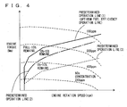
- Operation line setting unit 404 sets an operation line with a lower degree of generation of NOx in accordance with a decrease in the detected solution amount. For example, predetermined operation lines (1) to (3) shown in Fig. 4 are stored beforehand in storage unit 500. Operation line setting unit 404 reads an operation line corresponding to the detected solution amount from storage unit 500.
- the predetermined operation line (1) indicated by a solid line in Fig. 4 represents an optimum fuel efficiency operation line, and corresponds to an operation line of engine 120 when the solution amount is equal to or more than 15%.
- the predetermined operation line (2) indicated by a dash-dot line in Fig. 4 corresponds to an operation line of engine 120 when the solution amount is equal to or more than 10% and less than 15%.
- the predetermined operation line (3) indicated by a broken line in Fig. 4 corresponds to an operation line of engine 120 when the solution amount is equal to or more than 0% and less than 10%.
- the number of operation lines is not limited to three, and four or more operation lines may be used.
- the predetermined operation lines (1) to (3) are satisfactorily provided as long as they are adapted through experiments or the like, and in particular the predetermined operation line (3) is set such that appropriate exhaust gas purification performance is exhibited when the solution amount is 0%.
- the predetermined operation line (3) is set to have a lower degree of generation of torque with respect to the rotation speed of engine 120, when compared with the optimum fuel efficiency line. Thereby, an increase in the NOx concentration can be suppressed in an entire rotation range of engine 120, when compared with the predetermined operation line (1).
- the predetermined operation line (2) is set between the predetermined operation line (1) and the predetermined operation line (3).
- the predetermined operation line (2) is set to have a degree of generation of torque with respect to the rotation speed of engine 120 that is lower than that of the predetermined operation line (1) and higher than that of the predetermined operation line (3).
- operation line setting unit 404 reads one of the predetermined operation lines (1) to (3) from storage unit 500 and set the operation line.
- Operation line setting unit 404 may be configured, for example, to read and set the predetermined operation line (1) when the FULL-15% determination flag is on, may be configured to read and set the predetermined operation line (2) when the 10% determination flag is on, and may be configured to read and set the predetermined operation line (3) when the 0% determination flag is on.
- Engine control unit 406 controls engine 120 based on the set operation line. Specifically, a drive force required to the vehicle is specified based on an accelerator position and a vehicle speed. Based on the specified drive force and the set operation line, engine control unit 406 specifies an operation point on the operation line and controls engine 120 to be in an operation state corresponding to the specified operation point. For example, engine control unit 406 controls a throttle position, a fuel injection amount, ignition timing, and the like of engine 120, and controls engine 120 to be in an operation state corresponding to the specified operation point.
- engine control unit 406 controls engine 120 to be in an operation state corresponding to an operation point that has been moved from an operation point on the operation line before change onto a changed operation line, along an equal output line.
- MG control unit 408 controls MG(1) 140A and MG(2) 140B in parallel with the control of engine 120.
- MG control unit 408 sets a degree of power generation by engine 120 (i.e., a degree of a drive force to be transmitted from engine 120 to the wheels) based on the specified drive force, and controls MG(1) 140A to be in an operation state corresponding to the set degree.
- MG control unit 408 also sets a degree of a drive force to be transmitted from MG(2) 140B to the wheels based on the specified drive force, and controls MG(2) 140B to be in an operation state corresponding to the set degree.
- the required drive force is generated in the vehicle by the operation of engine 120, MG(1) 140A, and MG(2) 140B.
- Injection amount calculation unit 410 calculates a fuel injection amount for each time when engine 120 is rotated in a predetermined number of rotations. Injection amount calculation unit 410 may calculate the injection amount, for example, based on an integrated value of injection times in a period in which engine 120 is rotated in a predetermined number of rotations.
- Fuel efficiency calculation unit 412 calculates the degree of deterioration of fuel efficiency. For example, fuel efficiency calculation unit 412 calculates instantaneous fuel efficiency based on a traveling distance of the vehicle and the fuel injection amount for each time when engine 120 is rotated in a predetermined number of rotations. Fuel efficiency calculation unit 412 calculates the degree of deterioration of fuel efficiency in accordance with a deviation between an average value of instantaneous fuel efficiencies in a previous predetermined traveling period (distance or time) and an average value in the past. Alternatively, fuel efficiency calculation unit 412 may calculate the degree of deterioration of fuel efficiency in accordance with a deviation between average fuel efficiency in a previous predetermined traveling period and average fuel efficiency in the past.
- Display control unit 414 generates a display control signal corresponding to solution amount indicator 342 based on the determined solution amount, and sends the display control signal to display device 340 through output I/F 600.
- the display control signal corresponding to solution amount indicator 342 is, for example, a signal indicating which of the four illumination regions of solution amount indicator 342 is to be illuminated.
- display control unit 414 generates a display control signal corresponding to fuel efficiency indicator 344 based on the calculated degree of deterioration of fuel efficiency, and sends the display control signal to display device 340 through output I/F 600.
- the display control signal corresponding to fuel efficiency indicator 344 is, for example, a signal indicating which of the four illumination regions of fuel efficiency indicator 344 is to be illuminated.
- solution amount determination unit 402 operation line setting unit 404, engine control unit 406, MG control unit 408, injection amount calculation unit 410, fuel efficiency calculation unit 412, and display control unit 414 function as software implemented by an CPU (Central Processing Unit) as computation processing unit 400 executing a program stored in storage unit 500, they may be configured to be implemented by hardware. Such a program is recorded in a storage medium and mounted in the vehicle.
- CPU Central Processing Unit
- Storage unit 500 stores various types of information, programs, threshold values, maps, and the like, and data is read from computation processing unit 400 and stored therein, as necessary.
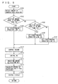
- step (hereinafter referred to as S) 100 ECU 320 detects the amount of the aqueous urea solution.
- ECU 320 determines whether or not the detected amount of the aqueous urea solution is equal to or more than 15%. If the detected amount of the aqueous urea solution is equal to or more than 15% (YES in S102), the process goes to S 104. Otherwise (NO in S 102), the process goes to S 106. In S104, ECU 320 sets the predetermined operation line (1) as an operation line of engine 120.
- ECU 320 determines whether or not the detected amount of the aqueous urea solution is equal to or more than 10%. If the amount of the aqueous urea solution is equal to or more than 10% (YES in S 106), the process goes to S 108. Otherwise (NO in S 106), the process goes to S110. In S 108, ECU 320 sets the predetermined operation line (2) as an operation line of engine 120.
- ECU 320 sets the predetermined operation line (3) as an operation line of engine 120.
- ECU 320 controls an output of engine 120 based on the traveling state of the vehicle (i.e., the accelerator position and the vehicle speed) and the set operation line.
- ECU 320 controls outputs of MG(1) 140A and MG(2) 140B based on the traveling state of the vehicle.
- ECU 320 calculates the fuel injection amount. In S118, ECU 320 calculates the degree of deterioration of fuel efficiency. In S120, ECU 320 controls display device 340 to display the amount of the aqueous urea solution and the degree of deterioration of fuel efficiency at solution amount indicator 342 and fuel efficiency indicator 344, respectively.
- ECU 320 as the control device for the vehicle in accordance with the present embodiment based on the structure and the flowchart described above will be described with reference to Fig. 6 .
- the predetermined operation line (1) indicated by the solid line in Fig. 6 is set as an operation line of engine 120 (S104). Accordingly, engine 120 is controlled to operate along the predetermined operation line (1) (S112). Along with the control of engine 120, MG(1) 140A and MG(2) 140B are controlled (S114).
- the fuel injection amount is calculated (S 116)
- the degree of deterioration of fuel efficiency is calculated (S 118)
- the solution amount and the degree of deterioration of fuel efficiency are displayed at solution amount indicator 342 and fuel efficiency indicator 344, respectively, of display device 340 (S120). Since engine 120 operates along the optimum fuel efficiency operation line, the four illumination regions are all illuminated in fuel efficiency indicator 344.
- the predetermined operation line (2) indicated by the dash-dot line in Fig. 6 is set as an operation line of engine 120 (S 108). Accordingly, engine 120 is controlled along the predetermined operation line (2) (S 112).
- the outputs of MG(1) 140A and MG(2) 140B are controlled (S114). Further, the fuel injection amount is calculated (S116), the degree of deterioration of fuel efficiency is calculated (S118), and the amount of the aqueous urea solution and the degree of deterioration of fuel efficiency are displayed at solution amount indicator 342 and fuel efficiency indicator 344, respectively, of display device 340 (S 120).
- the predetermined operation line (2) is an operation line set on a side with a lower NOx concentration when compared with the predetermined operation line (1), deterioration of the exhaust gas purification performance is suppressed. It is to be noted that, since the predetermined operation line (2) is an operation line deviated from the optimum fuel efficiency operation line, the fuel efficiency tends to be deteriorated when compared with a case where engine 120 is operated on the optimum fuel efficiency operation line. Therefore, in fuel efficiency indicator 344, only the illumination region on the deterioration side rather than the normal side is illuminated. Thereby, the driver is informed of a decrease in the solution amount and deterioration of the fuel efficiency.
- the predetermined operation line (3) indicated by the broken line in Fig. 6 is set as an operation line of engine 120 (S110). Accordingly, engine 120 is controlled along the predetermined operation line (3) (S 112).
- point A of Fig. 6 serves as the operation point when engine 120 is controlled along the predetermined operation line (1) and then the predetermined operation line (3) is set
- engine 120 is controlled using a point C of Fig. 6 as an operation point.
- point A and point C (and point B) have a relationship that they are operation points on the equal output line.
- the outputs of MG(1) 140A and MG(2) 140B are controlled (S114). Further, the fuel injection amount is calculated (S116), the degree of deterioration of fuel efficiency is calculated (S 118), and the amount of the aqueous urea solution and the degree of deterioration of fuel efficiency are displayed at solution amount indicator 342 and fuel efficiency indicator 344, respectively, of display device 340 (S 120).
- the predetermined operation line (3) is an operation line set on a side with a lower NOx concentration when compared with the predetermined operation lines (1) and (2), deterioration of the exhaust gas purification performance is further suppressed. It is to be noted that, since the predetermined operation line (3) is an operation line deviated from the optimum fuel efficiency operation line, the fuel efficiency tends to be deteriorated when compared with the case where engine 120 is operated on the optimum fuel efficiency line. Thereby, the driver is informed of a decrease in the solution amount and deterioration of the fuel efficiency.
- an operation line of the engine is changed to an operation line on a side with a lower NOx concentration step by step in accordance with a decrease in the amount of the aqueous urea solution, which suppresses the driver from feeling that the vehicle's behavior suddenly becomes not normal when no aqueous urea solution is left.
- the operation line of the engine is changed to an operation line with a lower degree of generation of NOx, an increase in the NOx concentration can be suppressed. Accordingly, an increase in the NOx concentration in exhaust gas can be suppressed.
- the driver can be urged to replenish the reducing agent. Consequently, the driver can be appropriately informed of presence or absence of the reducing agent.
- the present embodiment may employ a configuration controlling an output of the engine by detecting or calculating a residual amount of the aqueous urea solution in the aqueous urea solution tank reserving the aqueous urea solution as a reducing agent, and changing an operation point of the engine determined by the driver's request to an operation point on an equal output line with decreased emission of nitrogen oxide, in accordance with the detected or calculated residual amount of the aqueous urea solution.
- the configuration in accordance with the present invention described above may be applied to a hybrid vehicle, or a vehicle equipped with a CVT (Continuously Variable Transmission).
- CVT Continuous Variable Transmission
- the hybrid vehicle can be driven using electric power from a traveling battery, the hybrid vehicle has less restrictions in changing an operation point and has a higher degree of freedom, when compared with the vehicle equipped with a CVT.
Landscapes
- Engineering & Computer Science (AREA)
- Chemical & Material Sciences (AREA)
- Combustion & Propulsion (AREA)
- Mechanical Engineering (AREA)
- General Engineering & Computer Science (AREA)
- Transportation (AREA)
- Chemical Kinetics & Catalysis (AREA)
- Automation & Control Theory (AREA)
- Exhaust Gas After Treatment (AREA)
- Control Of Vehicle Engines Or Engines For Specific Uses (AREA)
- Hybrid Electric Vehicles (AREA)
- Electrical Control Of Air Or Fuel Supplied To Internal-Combustion Engine (AREA)
- Combined Controls Of Internal Combustion Engines (AREA)
- Exhaust Gas Treatment By Means Of Catalyst (AREA)
- Electric Propulsion And Braking For Vehicles (AREA)
Applications Claiming Priority (2)
| Application Number | Priority Date | Filing Date | Title |
|---|---|---|---|
| JP2008057687A JP4329866B1 (ja) | 2008-03-07 | 2008-03-07 | 車両の制御装置、制御方法およびその方法をコンピュータに実行させるプログラムならびにそのプログラムを記録した記録媒体 |
| PCT/JP2009/051547 WO2009110269A1 (ja) | 2008-03-07 | 2009-01-30 | 車両の制御装置および制御方法 |
Publications (3)
| Publication Number | Publication Date |
|---|---|
| EP2249016A1 true EP2249016A1 (de) | 2010-11-10 |
| EP2249016A4 EP2249016A4 (de) | 2017-10-11 |
| EP2249016B1 EP2249016B1 (de) | 2018-12-26 |
Family
ID=41055831
Family Applications (1)
| Application Number | Title | Priority Date | Filing Date |
|---|---|---|---|
| EP09717444.5A Not-in-force EP2249016B1 (de) | 2008-03-07 | 2009-01-30 | Vorrichtung und verfahren zur fahrzeugsteuerung |
Country Status (5)
| Country | Link |
|---|---|
| US (1) | US8473178B2 (de) |
| EP (1) | EP2249016B1 (de) |
| JP (1) | JP4329866B1 (de) |
| CN (1) | CN101960129B (de) |
| WO (1) | WO2009110269A1 (de) |
Cited By (2)
| Publication number | Priority date | Publication date | Assignee | Title |
|---|---|---|---|---|
| EP2565413A1 (de) * | 2011-09-01 | 2013-03-06 | Peugeot Citroën Automobiles Sa | Verfahren zum thermischen Schutz eines Abgasentgiftungsorgans einer Abgasleitung, und entsprechendes Fahrzeug |
| EP3199713A4 (de) * | 2014-09-24 | 2018-05-23 | Hitachi Construction Machinery Co., Ltd. | Anzeigevorrichtung für arbeitsmaschine |
Families Citing this family (20)
| Publication number | Priority date | Publication date | Assignee | Title |
|---|---|---|---|---|
| US9453753B2 (en) * | 2009-03-18 | 2016-09-27 | Crown Equipment Corporation | Fuel level meter for industrial vehicles |
| JP5617348B2 (ja) * | 2010-05-17 | 2014-11-05 | いすゞ自動車株式会社 | Scrシステム |
| JP5471831B2 (ja) | 2010-05-25 | 2014-04-16 | いすゞ自動車株式会社 | Scrシステム |
| US9030063B2 (en) | 2010-12-17 | 2015-05-12 | Tesla Motors, Inc. | Thermal management system for use with an integrated motor assembly |
| DE102010056399A1 (de) * | 2010-12-28 | 2012-06-28 | GM Global Technology Operations LLC | Kraftfahrzeug mit einem Abgasnachbehandlungssystem und Verfahren zum Betreiben des Kraftfahrzeuges |
| SE535932C2 (sv) * | 2011-04-19 | 2013-02-26 | Scania Cv Ab | Förfarande och anordning för bestämning av resterande volym reduktionsmedel i en behållare vid ett SCR-system |
| JP5862311B2 (ja) * | 2012-01-11 | 2016-02-16 | トヨタ自動車株式会社 | ハイブリッド車両 |
| JP5998506B2 (ja) * | 2012-02-13 | 2016-09-28 | 株式会社デンソー | ハイブリッド車両の制御装置 |
| DE102012204352B4 (de) * | 2012-03-01 | 2023-09-07 | Robert Bosch Gmbh | Verfahren zum Betreiben einer Antriebseinrichtung |
| JP5876571B2 (ja) * | 2014-02-18 | 2016-03-02 | 株式会社小松製作所 | 作業車両用表示装置及び作業車両 |
| KR101543162B1 (ko) * | 2014-05-09 | 2015-08-07 | 현대자동차주식회사 | 요소수 후처리 시스템, 촉감을 이용한 요소수 상태 경고방법 및 컨트롤러 |
| US20160082949A1 (en) * | 2014-09-22 | 2016-03-24 | Hyundai Motor Company | System for improving exhaust gas purifying performance of diesel hybrid electric vehicle |
| KR101673336B1 (ko) * | 2015-04-02 | 2016-11-07 | 현대자동차 주식회사 | 차량의 운전자 강제 유도 방법 및 장치 |
| JP6358179B2 (ja) * | 2015-07-16 | 2018-07-18 | トヨタ自動車株式会社 | 車両の自動運転システム |
| JP6319241B2 (ja) * | 2015-09-11 | 2018-05-09 | マツダ株式会社 | 発電機駆動用エンジン搭載の自動車 |
| US10059325B2 (en) * | 2016-07-21 | 2018-08-28 | Ford Global Technologies, Llc | Method and system for controlling water injection |
| JP6423026B2 (ja) | 2017-02-09 | 2018-11-14 | 本田技研工業株式会社 | ハイブリッド車 |
| JP6828705B2 (ja) * | 2018-03-12 | 2021-02-10 | トヨタ自動車株式会社 | 車両の制御装置 |
| US11377088B2 (en) | 2018-04-02 | 2022-07-05 | Cummins Inc. | Electric vehicles with engines and interaction with aftertreatment |
| JP7488228B2 (ja) * | 2021-07-28 | 2024-05-21 | 矢崎総業株式会社 | 車両用制御ユニット及び車両用制御システム |
Family Cites Families (17)
| Publication number | Priority date | Publication date | Assignee | Title |
|---|---|---|---|---|
| DE19629163C1 (de) * | 1996-07-19 | 1997-10-09 | Daimler Benz Ag | Verfahren und Vorrichtung zum stickoxidemissionsarmen Betrieb eines Verbrennungsmotors |
| US6063350A (en) | 1997-04-02 | 2000-05-16 | Clean Diesel Technologies, Inc. | Reducing nox emissions from an engine by temperature-controlled urea injection for selective catalytic reduction |
| JP3854013B2 (ja) * | 1999-06-10 | 2006-12-06 | 三菱電機株式会社 | 内燃機関の排出ガス浄化装置 |
| JP3613681B2 (ja) | 2001-04-23 | 2005-01-26 | トヨタ自動車株式会社 | 内燃機関の制御装置 |
| US6866610B2 (en) * | 2001-03-30 | 2005-03-15 | Toyota Jidosha Kabushiki Kaisha | Control apparatus and method for vehicle having internal combustion engine and continuously variable transmission, and control apparatus and method for internal combustion engine |
| JP2002371831A (ja) | 2001-06-13 | 2002-12-26 | Nissan Diesel Motor Co Ltd | 自動車の排ガス浄化装置 |
| US6421599B1 (en) * | 2001-08-09 | 2002-07-16 | Ford Global Technologies, Inc. | Control strategy for an internal combustion engine in a hybrid vehicle |
| JP3718209B2 (ja) | 2003-10-03 | 2005-11-24 | 日産ディーゼル工業株式会社 | エンジンの排気浄化装置 |
| JP4326976B2 (ja) | 2003-10-22 | 2009-09-09 | 日産ディーゼル工業株式会社 | エンジンの排気浄化装置 |
| JP4158733B2 (ja) * | 2004-03-29 | 2008-10-01 | 株式会社デンソー | 燃料噴射装置 |
| JP4308094B2 (ja) | 2004-06-23 | 2009-08-05 | 日野自動車株式会社 | 還元剤供給装置 |
| JP2006170057A (ja) | 2004-12-15 | 2006-06-29 | Toyota Motor Corp | ハイブリッド車両の内燃機関制御装置及び方法 |
| JP4375248B2 (ja) | 2005-02-17 | 2009-12-02 | 株式会社デンソー | 走行支援装置 |
| JP4444165B2 (ja) | 2005-06-10 | 2010-03-31 | 日産ディーゼル工業株式会社 | エンジンの排気浄化装置 |
| JP2006090334A (ja) * | 2005-12-21 | 2006-04-06 | Nissan Diesel Motor Co Ltd | エンジンの排ガス浄化装置 |
| US7861518B2 (en) * | 2006-01-19 | 2011-01-04 | Cummins Inc. | System and method for NOx reduction optimization |
| JP4937617B2 (ja) | 2006-03-24 | 2012-05-23 | 三菱ふそうトラック・バス株式会社 | 車両用内燃機関の排気浄化システム |
-
2008
- 2008-03-07 JP JP2008057687A patent/JP4329866B1/ja not_active Expired - Fee Related
-
2009
- 2009-01-30 EP EP09717444.5A patent/EP2249016B1/de not_active Not-in-force
- 2009-01-30 WO PCT/JP2009/051547 patent/WO2009110269A1/ja not_active Ceased
- 2009-01-30 CN CN200980108063.6A patent/CN101960129B/zh not_active Expired - Fee Related
- 2009-01-30 US US12/810,269 patent/US8473178B2/en not_active Expired - Fee Related
Non-Patent Citations (1)
| Title |
|---|
| See references of WO2009110269A1 * |
Cited By (3)
| Publication number | Priority date | Publication date | Assignee | Title |
|---|---|---|---|---|
| EP2565413A1 (de) * | 2011-09-01 | 2013-03-06 | Peugeot Citroën Automobiles Sa | Verfahren zum thermischen Schutz eines Abgasentgiftungsorgans einer Abgasleitung, und entsprechendes Fahrzeug |
| FR2979668A1 (fr) * | 2011-09-01 | 2013-03-08 | Peugeot Citroen Automobiles Sa | Procede de protection thermique d'un organe de depollution d'une ligne d'echappement et vehicule correspondant |
| EP3199713A4 (de) * | 2014-09-24 | 2018-05-23 | Hitachi Construction Machinery Co., Ltd. | Anzeigevorrichtung für arbeitsmaschine |
Also Published As
| Publication number | Publication date |
|---|---|
| US20100280740A1 (en) | 2010-11-04 |
| EP2249016A4 (de) | 2017-10-11 |
| EP2249016B1 (de) | 2018-12-26 |
| CN101960129B (zh) | 2014-01-08 |
| JP4329866B1 (ja) | 2009-09-09 |
| CN101960129A (zh) | 2011-01-26 |
| WO2009110269A1 (ja) | 2009-09-11 |
| US8473178B2 (en) | 2013-06-25 |
| JP2009215898A (ja) | 2009-09-24 |
Similar Documents
| Publication | Publication Date | Title |
|---|---|---|
| EP2249016B1 (de) | Vorrichtung und verfahren zur fahrzeugsteuerung | |
| US20110035136A1 (en) | Control device and control method for vehicle | |
| CN103249622B (zh) | 混合动力车辆的控制装置及控制方法 | |
| CN104071150B (zh) | 混合动力汽车 | |
| US20100063662A1 (en) | Control device and control method of hybrid vehicle | |
| EP2090486A1 (de) | Hybridfahrzeug- und fahrreichweiteanzeigeverfahren | |
| JP2011051395A (ja) | 車両の制御装置および制御方法 | |
| US10661812B2 (en) | Display device | |
| EP2386744A1 (de) | Steuervorrichtung für fahrzeuge | |
| JP2014080163A (ja) | ハイブリッド車両の制御装置 | |
| US20100058737A1 (en) | Control device and control method of hybrid vehicle | |
| JP2008105639A (ja) | ハイブリッド車両の制御装置 | |
| KR101113638B1 (ko) | 하이브리드 차량의 경제운전 안내 방법 | |
| JP2014051199A (ja) | プラグインハイブリッド車両の制御装置 | |
| JP2007245753A (ja) | ハイブリッド車両の制御装置 | |
| US8348804B2 (en) | Hybrid engine system with transient load assistance | |
| JP2009095143A (ja) | 車両の制御装置、制御方法およびその方法をコンピュータで実現されるプログラムならびにそのプログラムを記録した記録媒体 | |
| JP5239809B2 (ja) | 車両の制御装置および制御方法 | |
| JP2006170057A (ja) | ハイブリッド車両の内燃機関制御装置及び方法 | |
| JP2011235809A (ja) | 車両用制御装置および車両用制御方法 | |
| JP5018162B2 (ja) | 車両の制御装置、制御方法およびその方法をコンピュータに実現させるプログラムならびにそのプログラムを記録した記録媒体 | |
| US20240001906A1 (en) | Control device for hybrid vehicle | |
| US12539859B2 (en) | Control device for hybrid vehicle | |
| US12583436B2 (en) | Hybrid electric vehicle | |
| JP4737028B2 (ja) | デュアルフューエルエンジンの制御装置 |
Legal Events
| Date | Code | Title | Description |
|---|---|---|---|
| PUAI | Public reference made under article 153(3) epc to a published international application that has entered the european phase |
Free format text: ORIGINAL CODE: 0009012 |
|
| 17P | Request for examination filed |
Effective date: 20100617 |
|
| AK | Designated contracting states |
Kind code of ref document: A1 Designated state(s): AT BE BG CH CY CZ DE DK EE ES FI FR GB GR HR HU IE IS IT LI LT LU LV MC MK MT NL NO PL PT RO SE SI SK TR |
|
| AX | Request for extension of the european patent |
Extension state: AL BA RS |
|
| DAX | Request for extension of the european patent (deleted) | ||
| RAP1 | Party data changed (applicant data changed or rights of an application transferred) |
Owner name: TOYOTA JIDOSHA KABUSHIKI KAISHA |
|
| RA4 | Supplementary search report drawn up and despatched (corrected) |
Effective date: 20170907 |
|
| RIC1 | Information provided on ipc code assigned before grant |
Ipc: F02D 29/02 20060101ALI20170901BHEP Ipc: F01N 3/24 20060101ALI20170901BHEP Ipc: B60K 6/543 20071001ALI20170901BHEP Ipc: B60W 20/00 20160101ALI20170901BHEP Ipc: F02D 45/00 20060101AFI20170901BHEP Ipc: F01N 3/08 20060101ALI20170901BHEP Ipc: F02D 29/00 20060101ALI20170901BHEP Ipc: B60W 10/06 20060101ALI20170901BHEP Ipc: B60K 6/445 20071001ALI20170901BHEP Ipc: B60L 11/14 20060101ALI20170901BHEP Ipc: B01D 53/94 20060101ALI20170901BHEP Ipc: F02D 41/04 20060101ALI20170901BHEP Ipc: F02D 41/02 20060101ALI20170901BHEP |
|
| GRAP | Despatch of communication of intention to grant a patent |
Free format text: ORIGINAL CODE: EPIDOSNIGR1 |
|
| STAA | Information on the status of an ep patent application or granted ep patent |
Free format text: STATUS: GRANT OF PATENT IS INTENDED |
|
| INTG | Intention to grant announced |
Effective date: 20180703 |
|
| GRAS | Grant fee paid |
Free format text: ORIGINAL CODE: EPIDOSNIGR3 |
|
| GRAA | (expected) grant |
Free format text: ORIGINAL CODE: 0009210 |
|
| STAA | Information on the status of an ep patent application or granted ep patent |
Free format text: STATUS: THE PATENT HAS BEEN GRANTED |
|
| AK | Designated contracting states |
Kind code of ref document: B1 Designated state(s): AT BE BG CH CY CZ DE DK EE ES FI FR GB GR HR HU IE IS IT LI LT LU LV MC MK MT NL NO PL PT RO SE SI SK TR |
|
| REG | Reference to a national code |
Ref country code: GB Ref legal event code: FG4D |
|
| REG | Reference to a national code |
Ref country code: CH Ref legal event code: EP |
|
| REG | Reference to a national code |
Ref country code: DE Ref legal event code: R096 Ref document number: 602009056383 Country of ref document: DE |
|
| REG | Reference to a national code |
Ref country code: AT Ref legal event code: REF Ref document number: 1081756 Country of ref document: AT Kind code of ref document: T Effective date: 20190115 |
|
| REG | Reference to a national code |
Ref country code: IE Ref legal event code: FG4D |
|
| REG | Reference to a national code |
Ref country code: CH Ref legal event code: PK Free format text: BERICHTIGUNGEN |
|
| RIC2 | Information provided on ipc code assigned after grant |
Ipc: F02D 41/04 20060101ALI20170901BHEP Ipc: F02D 41/02 20060101ALI20170901BHEP Ipc: B60K 6/445 20071001ALI20170901BHEP Ipc: F01N 3/08 20060101ALI20170901BHEP Ipc: F02D 45/00 20060101AFI20170901BHEP Ipc: B60K 6/543 20071001ALI20170901BHEP Ipc: B60L 11/14 20060101ALI20170901BHEP Ipc: B60W 10/06 20060101ALI20170901BHEP Ipc: B01D 53/94 20060101ALI20170901BHEP Ipc: F02D 29/00 20060101ALI20170901BHEP Ipc: F02D 29/02 20060101ALI20170901BHEP Ipc: F01N 3/24 20060101ALI20170901BHEP Ipc: B60W 20/00 20160101ALI20170901BHEP |
|
| REG | Reference to a national code |
Ref country code: DE Ref legal event code: R084 Ref document number: 602009056383 Country of ref document: DE |
|
| PG25 | Lapsed in a contracting state [announced via postgrant information from national office to epo] |
Ref country code: LV Free format text: LAPSE BECAUSE OF FAILURE TO SUBMIT A TRANSLATION OF THE DESCRIPTION OR TO PAY THE FEE WITHIN THE PRESCRIBED TIME-LIMIT Effective date: 20181226 Ref country code: LT Free format text: LAPSE BECAUSE OF FAILURE TO SUBMIT A TRANSLATION OF THE DESCRIPTION OR TO PAY THE FEE WITHIN THE PRESCRIBED TIME-LIMIT Effective date: 20181226 Ref country code: BG Free format text: LAPSE BECAUSE OF FAILURE TO SUBMIT A TRANSLATION OF THE DESCRIPTION OR TO PAY THE FEE WITHIN THE PRESCRIBED TIME-LIMIT Effective date: 20190326 Ref country code: HR Free format text: LAPSE BECAUSE OF FAILURE TO SUBMIT A TRANSLATION OF THE DESCRIPTION OR TO PAY THE FEE WITHIN THE PRESCRIBED TIME-LIMIT Effective date: 20181226 Ref country code: FI Free format text: LAPSE BECAUSE OF FAILURE TO SUBMIT A TRANSLATION OF THE DESCRIPTION OR TO PAY THE FEE WITHIN THE PRESCRIBED TIME-LIMIT Effective date: 20181226 Ref country code: NO Free format text: LAPSE BECAUSE OF FAILURE TO SUBMIT A TRANSLATION OF THE DESCRIPTION OR TO PAY THE FEE WITHIN THE PRESCRIBED TIME-LIMIT Effective date: 20190326 |
|
| REG | Reference to a national code |
Ref country code: NL Ref legal event code: MP Effective date: 20181226 |
|
| REG | Reference to a national code |
Ref country code: LT Ref legal event code: MG4D |
|
| PG25 | Lapsed in a contracting state [announced via postgrant information from national office to epo] |
Ref country code: GR Free format text: LAPSE BECAUSE OF FAILURE TO SUBMIT A TRANSLATION OF THE DESCRIPTION OR TO PAY THE FEE WITHIN THE PRESCRIBED TIME-LIMIT Effective date: 20190327 Ref country code: SE Free format text: LAPSE BECAUSE OF FAILURE TO SUBMIT A TRANSLATION OF THE DESCRIPTION OR TO PAY THE FEE WITHIN THE PRESCRIBED TIME-LIMIT Effective date: 20181226 |
|
| REG | Reference to a national code |
Ref country code: AT Ref legal event code: MK05 Ref document number: 1081756 Country of ref document: AT Kind code of ref document: T Effective date: 20181226 |
|
| PG25 | Lapsed in a contracting state [announced via postgrant information from national office to epo] |
Ref country code: NL Free format text: LAPSE BECAUSE OF FAILURE TO SUBMIT A TRANSLATION OF THE DESCRIPTION OR TO PAY THE FEE WITHIN THE PRESCRIBED TIME-LIMIT Effective date: 20181226 |
|
| PG25 | Lapsed in a contracting state [announced via postgrant information from national office to epo] |
Ref country code: ES Free format text: LAPSE BECAUSE OF FAILURE TO SUBMIT A TRANSLATION OF THE DESCRIPTION OR TO PAY THE FEE WITHIN THE PRESCRIBED TIME-LIMIT Effective date: 20181226 Ref country code: PT Free format text: LAPSE BECAUSE OF FAILURE TO SUBMIT A TRANSLATION OF THE DESCRIPTION OR TO PAY THE FEE WITHIN THE PRESCRIBED TIME-LIMIT Effective date: 20190426 Ref country code: CZ Free format text: LAPSE BECAUSE OF FAILURE TO SUBMIT A TRANSLATION OF THE DESCRIPTION OR TO PAY THE FEE WITHIN THE PRESCRIBED TIME-LIMIT Effective date: 20181226 Ref country code: IT Free format text: LAPSE BECAUSE OF FAILURE TO SUBMIT A TRANSLATION OF THE DESCRIPTION OR TO PAY THE FEE WITHIN THE PRESCRIBED TIME-LIMIT Effective date: 20181226 Ref country code: PL Free format text: LAPSE BECAUSE OF FAILURE TO SUBMIT A TRANSLATION OF THE DESCRIPTION OR TO PAY THE FEE WITHIN THE PRESCRIBED TIME-LIMIT Effective date: 20181226 |
|
| PG25 | Lapsed in a contracting state [announced via postgrant information from national office to epo] |
Ref country code: SK Free format text: LAPSE BECAUSE OF FAILURE TO SUBMIT A TRANSLATION OF THE DESCRIPTION OR TO PAY THE FEE WITHIN THE PRESCRIBED TIME-LIMIT Effective date: 20181226 Ref country code: EE Free format text: LAPSE BECAUSE OF FAILURE TO SUBMIT A TRANSLATION OF THE DESCRIPTION OR TO PAY THE FEE WITHIN THE PRESCRIBED TIME-LIMIT Effective date: 20181226 Ref country code: IS Free format text: LAPSE BECAUSE OF FAILURE TO SUBMIT A TRANSLATION OF THE DESCRIPTION OR TO PAY THE FEE WITHIN THE PRESCRIBED TIME-LIMIT Effective date: 20190426 Ref country code: RO Free format text: LAPSE BECAUSE OF FAILURE TO SUBMIT A TRANSLATION OF THE DESCRIPTION OR TO PAY THE FEE WITHIN THE PRESCRIBED TIME-LIMIT Effective date: 20181226 |
|
| REG | Reference to a national code |
Ref country code: CH Ref legal event code: PL |
|
| REG | Reference to a national code |
Ref country code: DE Ref legal event code: R097 Ref document number: 602009056383 Country of ref document: DE |
|
| PG25 | Lapsed in a contracting state [announced via postgrant information from national office to epo] |
Ref country code: LU Free format text: LAPSE BECAUSE OF NON-PAYMENT OF DUE FEES Effective date: 20190130 |
|
| REG | Reference to a national code |
Ref country code: BE Ref legal event code: MM Effective date: 20190131 |
|
| REG | Reference to a national code |
Ref country code: IE Ref legal event code: MM4A |
|
| PG25 | Lapsed in a contracting state [announced via postgrant information from national office to epo] |
Ref country code: MC Free format text: LAPSE BECAUSE OF FAILURE TO SUBMIT A TRANSLATION OF THE DESCRIPTION OR TO PAY THE FEE WITHIN THE PRESCRIBED TIME-LIMIT Effective date: 20181226 Ref country code: AT Free format text: LAPSE BECAUSE OF FAILURE TO SUBMIT A TRANSLATION OF THE DESCRIPTION OR TO PAY THE FEE WITHIN THE PRESCRIBED TIME-LIMIT Effective date: 20181226 Ref country code: DK Free format text: LAPSE BECAUSE OF FAILURE TO SUBMIT A TRANSLATION OF THE DESCRIPTION OR TO PAY THE FEE WITHIN THE PRESCRIBED TIME-LIMIT Effective date: 20181226 |
|
| PLBE | No opposition filed within time limit |
Free format text: ORIGINAL CODE: 0009261 |
|
| STAA | Information on the status of an ep patent application or granted ep patent |
Free format text: STATUS: NO OPPOSITION FILED WITHIN TIME LIMIT |
|
| GBPC | Gb: european patent ceased through non-payment of renewal fee |
Effective date: 20190326 |
|
| PG25 | Lapsed in a contracting state [announced via postgrant information from national office to epo] |
Ref country code: BE Free format text: LAPSE BECAUSE OF NON-PAYMENT OF DUE FEES Effective date: 20190131 |
|
| 26N | No opposition filed |
Effective date: 20190927 |
|
| PG25 | Lapsed in a contracting state [announced via postgrant information from national office to epo] |
Ref country code: LI Free format text: LAPSE BECAUSE OF NON-PAYMENT OF DUE FEES Effective date: 20190131 Ref country code: CH Free format text: LAPSE BECAUSE OF NON-PAYMENT OF DUE FEES Effective date: 20190131 |
|
| PG25 | Lapsed in a contracting state [announced via postgrant information from national office to epo] |
Ref country code: IE Free format text: LAPSE BECAUSE OF NON-PAYMENT OF DUE FEES Effective date: 20190130 Ref country code: GB Free format text: LAPSE BECAUSE OF NON-PAYMENT OF DUE FEES Effective date: 20190326 |
|
| PG25 | Lapsed in a contracting state [announced via postgrant information from national office to epo] |
Ref country code: SI Free format text: LAPSE BECAUSE OF FAILURE TO SUBMIT A TRANSLATION OF THE DESCRIPTION OR TO PAY THE FEE WITHIN THE PRESCRIBED TIME-LIMIT Effective date: 20181226 Ref country code: FR Free format text: LAPSE BECAUSE OF NON-PAYMENT OF DUE FEES Effective date: 20190226 |
|
| PG25 | Lapsed in a contracting state [announced via postgrant information from national office to epo] |
Ref country code: TR Free format text: LAPSE BECAUSE OF FAILURE TO SUBMIT A TRANSLATION OF THE DESCRIPTION OR TO PAY THE FEE WITHIN THE PRESCRIBED TIME-LIMIT Effective date: 20181226 |
|
| PG25 | Lapsed in a contracting state [announced via postgrant information from national office to epo] |
Ref country code: MT Free format text: LAPSE BECAUSE OF NON-PAYMENT OF DUE FEES Effective date: 20190130 |
|
| PG25 | Lapsed in a contracting state [announced via postgrant information from national office to epo] |
Ref country code: CY Free format text: LAPSE BECAUSE OF FAILURE TO SUBMIT A TRANSLATION OF THE DESCRIPTION OR TO PAY THE FEE WITHIN THE PRESCRIBED TIME-LIMIT Effective date: 20181226 |
|
| PGFP | Annual fee paid to national office [announced via postgrant information from national office to epo] |
Ref country code: DE Payment date: 20210119 Year of fee payment: 13 |
|
| PG25 | Lapsed in a contracting state [announced via postgrant information from national office to epo] |
Ref country code: HU Free format text: LAPSE BECAUSE OF FAILURE TO SUBMIT A TRANSLATION OF THE DESCRIPTION OR TO PAY THE FEE WITHIN THE PRESCRIBED TIME-LIMIT; INVALID AB INITIO Effective date: 20090130 |
|
| PG25 | Lapsed in a contracting state [announced via postgrant information from national office to epo] |
Ref country code: MK Free format text: LAPSE BECAUSE OF FAILURE TO SUBMIT A TRANSLATION OF THE DESCRIPTION OR TO PAY THE FEE WITHIN THE PRESCRIBED TIME-LIMIT Effective date: 20181226 |
|
| REG | Reference to a national code |
Ref country code: DE Ref legal event code: R119 Ref document number: 602009056383 Country of ref document: DE |
|
| PG25 | Lapsed in a contracting state [announced via postgrant information from national office to epo] |
Ref country code: DE Free format text: LAPSE BECAUSE OF NON-PAYMENT OF DUE FEES Effective date: 20220802 |