EP2248770B1 - Kapillar-Wasserverteiler und dessen Verwendung in Kläranlagen für häusliches Abwasser - Google Patents
Kapillar-Wasserverteiler und dessen Verwendung in Kläranlagen für häusliches Abwasser Download PDFInfo
- Publication number
- EP2248770B1 EP2248770B1 EP10160124.3A EP10160124A EP2248770B1 EP 2248770 B1 EP2248770 B1 EP 2248770B1 EP 10160124 A EP10160124 A EP 10160124A EP 2248770 B1 EP2248770 B1 EP 2248770B1
- Authority
- EP
- European Patent Office
- Prior art keywords
- water
- trough
- capillary
- watertight
- plant
- Prior art date
- Legal status (The legal status is an assumption and is not a legal conclusion. Google has not performed a legal analysis and makes no representation as to the accuracy of the status listed.)
- Not-in-force
Links
Images

Classifications
-
- E—FIXED CONSTRUCTIONS
- E03—WATER SUPPLY; SEWERAGE
- E03F—SEWERS; CESSPOOLS
- E03F1/00—Methods, systems, or installations for draining-off sewage or storm water
- E03F1/002—Methods, systems, or installations for draining-off sewage or storm water with disposal into the ground, e.g. via dry wells
-
- C—CHEMISTRY; METALLURGY
- C02—TREATMENT OF WATER, WASTE WATER, SEWAGE, OR SLUDGE
- C02F—TREATMENT OF WATER, WASTE WATER, SEWAGE, OR SLUDGE
- C02F3/00—Biological treatment of water, waste water, or sewage
- C02F3/02—Aerobic processes
- C02F3/12—Activated sludge processes
- C02F3/1236—Particular type of activated sludge installations
- C02F3/1242—Small compact installations for use in homes, apartment blocks, hotels or the like
-
- C—CHEMISTRY; METALLURGY
- C02—TREATMENT OF WATER, WASTE WATER, SEWAGE, OR SLUDGE
- C02F—TREATMENT OF WATER, WASTE WATER, SEWAGE, OR SLUDGE
- C02F1/00—Treatment of water, waste water, or sewage
- C02F1/006—Water distributors either inside a treatment tank or directing the water to several treatment tanks; Water treatment plants incorporating these distributors, with or without chemical or biological tanks
-
- C—CHEMISTRY; METALLURGY
- C02—TREATMENT OF WATER, WASTE WATER, SEWAGE, OR SLUDGE
- C02F—TREATMENT OF WATER, WASTE WATER, SEWAGE, OR SLUDGE
- C02F2103/00—Nature of the water, waste water, sewage or sludge to be treated
- C02F2103/001—Runoff or storm water
-
- C—CHEMISTRY; METALLURGY
- C02—TREATMENT OF WATER, WASTE WATER, SEWAGE, OR SLUDGE
- C02F—TREATMENT OF WATER, WASTE WATER, SEWAGE, OR SLUDGE
- C02F2103/00—Nature of the water, waste water, sewage or sludge to be treated
- C02F2103/002—Grey water, e.g. from clothes washers, showers or dishwashers
-
- C—CHEMISTRY; METALLURGY
- C02—TREATMENT OF WATER, WASTE WATER, SEWAGE, OR SLUDGE
- C02F—TREATMENT OF WATER, WASTE WATER, SEWAGE, OR SLUDGE
- C02F3/00—Biological treatment of water, waste water, or sewage
- C02F3/02—Aerobic processes
- C02F3/12—Activated sludge processes
- C02F3/1236—Particular type of activated sludge installations
- C02F3/1263—Sequencing batch reactors [SBR]
-
- C—CHEMISTRY; METALLURGY
- C02—TREATMENT OF WATER, WASTE WATER, SEWAGE, OR SLUDGE
- C02F—TREATMENT OF WATER, WASTE WATER, SEWAGE, OR SLUDGE
- C02F3/00—Biological treatment of water, waste water, or sewage
- C02F3/32—Biological treatment of water, waste water, or sewage characterised by the animals or plants used, e.g. algae
- C02F3/327—Biological treatment of water, waste water, or sewage characterised by the animals or plants used, e.g. algae characterised by animals and plants
-
- Y—GENERAL TAGGING OF NEW TECHNOLOGICAL DEVELOPMENTS; GENERAL TAGGING OF CROSS-SECTIONAL TECHNOLOGIES SPANNING OVER SEVERAL SECTIONS OF THE IPC; TECHNICAL SUBJECTS COVERED BY FORMER USPC CROSS-REFERENCE ART COLLECTIONS [XRACs] AND DIGESTS
- Y02—TECHNOLOGIES OR APPLICATIONS FOR MITIGATION OR ADAPTATION AGAINST CLIMATE CHANGE
- Y02W—CLIMATE CHANGE MITIGATION TECHNOLOGIES RELATED TO WASTEWATER TREATMENT OR WASTE MANAGEMENT
- Y02W10/00—Technologies for wastewater treatment
- Y02W10/10—Biological treatment of water, waste water, or sewage
Definitions
- the invention relates to a capillary system and its use in sewage treatment plants for domestic wastewater. Furthermore, the invention relates to a method for sewage and / or rainwater treatment in which the wastewater is collected, optionally prepurified and then cleaned the prepurified water by means of a capillary system according to the invention, evaporated and / or released as moisture to the surrounding soil rich and / or Plant irrigation and hot water use is used. According to the invention, the receiving water and / or a device for infiltration of the clear water into macropores can thereby be eliminated, which is particularly necessary in regions with sensitive waters.
- the utilization of the purified waste water on site is particularly advantageous from an ecological as well as an economic point of view and corresponds to the Requirements of the international Agenda 21, to close water and raw material cycles as locally as possible.
- Purified wastewater and / or service water should therefore be reused for the formation of groundwater on site.
- the DE 103 30 369 A1 proposes, therefore, to increase the top surface of the terrain by means of local fillings so that the groundwater level is permanently lower than approximately 1.20 m below the ground level so that infiltration is possible again.
- landfills are always an intervention in landscaping and therefore can not be used nationwide.
- the increase in soil level is very material intensive and is only in question if surpluses, such as waste dumps or the like, are available.
- the font JP 55015608 A discloses a water treatment tank connected to a treatment tank 6 via a distribution chamber 1.
- the pretreated water is introduced via a perforated tube 11 into the lower third of the container 6, which is filled with water-permeable layers of gravel and sand.
- a further perforated tube is arranged, which opens above the water level WL in the distribution chamber 1.
- the invention accordingly relates to a capillary system which has at least one water reservoir, at least one water-impermeable well with a specific height, at least one water feed, the means for generating and / or maintaining a flow of water from the at least one water reservoir into the at least one water-impermeable well, at least one overflow protection that watertight connects the at least one water-impermeable tub with the at least one water reservoir, and at least one organic and / or inorganic substrate, which is arranged in the at least one water-impermeable tub and has a capillary action, wherein the capillary system so in Soil can be arranged that the tub bottom the ground surface of the ground opposite and the distance from the bottom of the tank to the ground level is equal to or greater than the height of the water-impermeable tub.
- any container can be used as a water reservoir according to the invention.
- Exemplary containers are made of stainless steel or plastic, e.g. Polyethylene (PE), polypropylene (PP) or polytetrafluoroethylene (PTFE) manufactured. Other suitable materials for water storage tanks are known in the art.
- the water reservoir according to the invention may be a single container or part of an upstream treatment plant. In a preferred embodiment of the invention, the water reservoir on rainwater and / or purified wastewater or clear water.
- the at least one water-impermeable trough comprises a trough bottom, a circumferential side wall or a plurality of side walls and an opening, which is a surface opposite the trough bottom and through the upper, i. the edge facing away from the tub bottom of the peripheral side wall is limited.
- the height of the water-impermeable tub extends from the bottom of the tub to the opening.
- the tank bottom can be configured in any desired shape, preferably round, elliptical or polygonal.
- the water-impermeable trough according to the invention has one circumferential or several adjoining side walls. If there are several side walls, they are preferably the same height.
- the angle between the tub bottom and the peripheral side wall is an obtuse angle. This means that water-impermeable troughs are preferred in which the opening of the trough is larger than the trough bottom.
- the water-impermeable tub according to the invention preferably consists of stainless steel or plastic, such as PE, PP or PTFE, particularly preferably PE.
- suitable materials are known to the person skilled in the art.
- the material thickness of the water-impermeable trough is preferably chosen such that, despite possibly in the soil befind Anlagen stones or similar pointed objects, there is no risk of leaks, cracks and / or holes. Material thicknesses of at least 1 mm, preferably at least 1.2 mm are sufficient according to the invention. To form the water-impermeable well, therefore, can also from the films suitable materials are used in the intended strength, with which a suitable depression in the ground is designed.
- the height of the water-impermeable trough 0.1 to 3 m, preferably 0.5 to 1.5 m.
- the diameter of the water-impermeable tub or its opening can be designed variably and is adapted to the amount of water to be cleaned and evaporated. Typical area sizes are in the range of 1 to 500 m 2 , preferably in the range of 5 to 100 m 2 , more preferably in the range of 10 to 20 m 2 .
- the at least one water supply is arranged according to the invention such that the distance of the water supply to the tank bottom is a maximum ofillon the height of the water-impermeable trough.
- the water supply is arranged as close as possible to the tank bottom and the water supply thus takes place from below.
- the water applied to the bottom of the tank then rises according to the invention as moisture mediated by the capillary forces of the inorganic and / or organic substrate in the water-impermeable tank.
- the water supply can be arranged in the at least one side wall or in the tank bottom.
- the water supply is a drainage pipe, which is preferably arranged parallel to the tub bottom.
- the drainage tube is thereby guided either through the side wall or through the opening of the water-impermeable trough in this.
- the drainage pipe according to the invention is guided as close as possible to the bottom of the tank and over the entire surface of the tank bottom.
- a long drainage pipe which is laid in loops, as well as a plurality of drainage pipes, which branch off from a central water supply, are provided. Suitable embodiments are known to the person skilled in the art.
- the drainage tube according to the invention is preferably made of stainless steel or plastic, e.g. PE, PP or PTFE, more preferably PE.
- the drainage pipe has at least one loading and / or deaerating.
- This is preferably a cylinder that connects the drainage pipe with the ambient air.
- the ventilator is arranged perpendicular to the drainage pipe. By means of the ventilator, gases still present in the treated wastewater can escape. moreover The wastewater comes into contact with oxygen and transfers it together with the wastewater into the substrate present in the water-impermeable tank.
- the ventilator is equipped with a filter, preferably a biofilter.
- a filter preferably a biofilter.
- the breather and / or deaerator has means for absorbing and / or decomposing organic and / or inorganic gases, preferably activated carbon, burl wood chips, wood chips and / or microorganisms.
- Further suitable filter materials are known to the person skilled in the art. If microorganisms are used to break down organic and / or inorganic gases, it is important that the filters do not dry out.
- the filter material is preferably a material with a large water storage capacity or it has wicks that moisten the filter from the drainage pipe with water.
- the capillary system further comprises an overflow protection, which connects the water-impermeable tank with the water reservoir.
- the overflow protection is arranged in the upper region of the water-impermeable trough.
- the distance of the overflow protection to the tank bottom is at least 2/3 of the height of the water-impermeable tank. More preferably, the distance of the overflow protection to the tank bottom is a maximum of 95%, more preferably a maximum of 90%, more preferably a maximum of 80% of the height of the water-impermeable tank.
- the overflow protection regulates the maximum level of the water-impermeable tub and prevents overflow.
- the water-impermeable tub is filled to about 50 to 60%, in burst mode or overloading excess water is transferred through the overflow protection in the water reservoir.
- overflow protection any tube or hose can be used.
- waterproof tub and water reservoir are arranged so that the overflow protection has a slight slope and the water automatically flows back into the water reservoir.
- means for actively transporting the water such as a pump, can also be provided in the overflow protection.
- the part of the overflow protection that reaches into the water-impermeable tub is closed with a filter or a sieve, so that solid components, such as the substrate, are retained, and only the water runs through the overflow protection.
- the water-impermeable tub according to the invention is filled with an organic and / or inorganic substrate, which according to the invention has a capillary action.
- an ascending capillary pressure is generated in the impermeable tub. This ensures that the liquid water present exclusively in the lower region of the water-impermeable trough rises as moisture in the substrate, that is to say in the soil matrix, and thus reaches the surface or near the roots of the plants to be watered.
- the rising damp can also be delivered to the soil surrounding the water-impermeable tank or the soil surrounding the tank.
- textile wicks preferably of natural fibers, synthetic fibers and / or glass fibers, may additionally or alternatively be provided in the organic and / or inorganic substrate, which additionally exert a capillary action or reinforce it.
- the organic and / or inorganic capillary substrate preferably comprises sand, gravel, gravel, clay, expanded clay, lava, textile fabric mats consisting of natural fibers, plastic fibers and / or glass fibers, a mixture thereof and / or a mixture with those above called wicks.
- the particle size or particle size of the organic and / or inorganic substrate is preferably in the range from 0.2 to 20 mm, more preferably in the range from 1 to 20 mm, more preferably in the range of 1 to 10 mm, most preferably in the range of 2 to 8 mm.
- the filling level of the organic and / or inorganic substrate in the water-impermeable trough is equal to or greater than the height of the water-impermeable trough.
- the water-impermeable trough is preferably completely filled with the organic and / or inorganic substrate or the substrate projects beyond the upper edge of the side walls.
- the water-impermeable trough can be arranged just deep enough in the topsoil or in the soil that the edges of the side walls terminate with the terrain upper edge.
- the water-impermeable pan is arranged deeper in the ground.
- the filling height is equal to or greater than the distance from the trough floor to the ground level. This means that the organic and / or inorganic substrate is piled up as a kind of bed above the ground level. Furthermore, the organic and / or inorganic substrate can extend laterally beyond the side walls of the water-impermeable trough, so that a transition from the organic and / or inorganic substrate to the surrounding soil is formed.
- an additional second or further water-impermeable trough is arranged below the water-impermeable trough, ie deeper in the ground.
- This second tub also has a tub bottom, at least one circumferential side wall and an opening, wherein the opening is a surface opposite the tub bottom and is limited by the tub bottom opposite edge of the at least one circumferential side wall.
- the volume of the additional water-impermeable trough is greater than the volume of the first water-impermeable trough.
- the second additional water-impermeable tub is placed in the ground such that the first water-impermeable tub is arranged in the second water-impermeable tub and the openings of the two tubs are positioned at the ground level.
- the additional water-impermeable pan represents a further delimitation of the surrounding soil from the environment, in particular with respect to the groundwater.
- the first water-impermeable pan is also against overflowing or secured against leaks in the floor or wall area.
- the rising in the soil matrix through the capillary forces moisture does not pass directly into the unsecured soil, but is collected again in an additional separated area of the soil. This is particularly advantageous if due to a high utilization of the system from the moisture after rising in the first water-impermeable tub and passage into the surrounding soil by saturation in the surrounding soil again water droplets should form, which could otherwise seep.
- the capillary system according to the invention is thus equipped with a double bottom and therefore advantageously satisfies the legal requirements.
- the further second water-impermeable trough is preferably made of the same materials as the first water-impermeable trough according to the invention.
- plastic films, more preferably PE films are used to form the additional water-impermeable pan, with which a suitable depression in the ground is designed.
- the additional water-impermeable tub has a larger volume than the first water-impermeable tub.
- the trough bottom of the second water-impermeable trough is clear, i. preferably increased by a factor of 1.2 to 5, particularly preferably by a factor of 1.2 to 2.
- the height of the second water-impermeable trough is preferably only slightly increased in order to be able to use the capillary system according to the invention even when the groundwater is high.
- the volume of the second water-impermeable well, which is not occupied by the first water-impermeable pan, is preferably filled with the sand surrounding the capillary system or the surrounding soil.
- the additional water-impermeable trough on a closable drain is preferably arranged in the region of the tank bottom and connects the additional water-impermeable tank waterproof with the water reservoir. If it comes to a formation of water droplets by saturation of the soil in the additional water-impermeable tub, this is discharged through the drain and directed back into the water reservoir. Thus, moisture, which precipitates again as water, are fed back into the capillary circulation.
- any tube or hose can be used.
- the additional water-impermeable tub and the water reservoir arranged such that the drain has a slight slope and the water automatically flows back into the water reservoir.
- the closable drain additionally has a filter or a sieve, so that solid components, such as the soil, are retained.
- the closable drain is connected watertight to a collection and / or inspection shaft.
- a collecting and / or inspection shaft according to the invention a container understood, which is also embedded in the ground and accessible from the top of the terrain. From the collection and / or inspection shaft water samples can be taken and fed to an analysis. Hygienically safe, collected in the collection and / or inspection shaft water can then be a normal receiving water or a process water recovery, for example, in the toilet flush, fed.
- the collection and / or inspection shaft is connected to the water reservoir, so that overflow is prevented and excess water is supplied to the capillary cycle again.
- the organic and / or inorganic substrate bank plants (littoral Helophyten) and / or marsh plants (Helophyten), preferably reed plants (Arundophyten), Sauergrasgewentese (Cyperaceae) and / or rushes (Juncaceae), even more preferably rushes ( Juncus), up.
- the soil arranged in the second water-impermeable tank is also overgrown with said bank plants and / or marsh plants.
- the capillary plant is arranged in the ground, that the bottom of the first water-impermeable tub and the additional second water-impermeable tub are arranged opposite to the ground surface of the soil and the distance from the bottom of the first water-impermeable tub to the ground level or equal greater than the height of the first water-impermeable tub.
- the first water-impermeable tank can be flush with the ground level or completely covered by soil.
- the water-impermeable trough can be arranged deeper in the ground, so that over the trough opening still a layer of soil is arranged.
- the preferred distance between the tub bottom and the ground level is a maximum of 30 cm, preferably a maximum of 20 cm, more preferably 5 to 10 cm greater than the height of the water-impermeable tub.
- this is preferably arranged so deep in the ground that the edges of their side surfaces and their opening complete with the ground level.
- the capillary system is in the soil, i. arranged in the topsoil of an outdoor area.
- the soil of a greenhouse or a comparable plant breeding building is in the soil, i. arranged in the topsoil of an outdoor area.
- the invention further relates to a sewage treatment plant having at least one capillary plant of the invention.
- the capillary system according to the invention can be used instead of a receiving water in municipal sewage treatment plants.
- the sewage treatment plant which has a capillary plant according to the invention, is a micro sewage treatment plant with a maximum wastewater volume of 8 m 3 / d or a small sewage treatment plant with a sewage volume of 8 to 800 m 3 / d.
- This corresponds to a population of approx. 50 inhabitants connected to the wastewater treatment plant at the micro sewage treatment plant or 50 - 5000 inhabitants at the small sewage treatment plant.
- the capillary system according to the invention replaced in this arrangement, the Verrieselungs vom.
- the invention is thus preferably used both on land of single-family homes and / or cottages as well as for incurred in larger buildings and / or housing complexes wastewater.
- the capillary system according to the invention can also be used in other collection or storage units and / or water treatment plants and / or retrofitted.
- collected rainwater such as rainwater collected from roof surfaces or water collected on other, at least partially water impermeable surfaces and treated as needed, may be used in the capillary system according to the invention.
- the treatment plant comprises a drainage-free collection pit for domestic wastewater and / or a system for sequential biological purification (SBR system), a means for composting the thick matter, preferably a thermal composter, and a capillary system according to the invention.
- SBR system sequential biological purification
- the drainage-free sump and / or the SBR basin of the SBR system is the water reservoir of the capillary system.
- a drainage-free collection pit is a container used to collect and store domestic wastewater. The disposal takes place depending on the amount of sewage once or twice a year. In the standing waste water, however, settle the solids, so that a pre-cleaning takes place and the supernatant water can be transferred to a capillary system according to the invention.
- a sewage treatment plant according to the invention preferably has an SBR system.
- This is a two-stage system.
- the first basin i. the mud reservoir fulfills similar functions as a drainage-free collection pit.
- the second basin the actual SBR basin takes place intermittently a biological purification of the supernatant water from the mud reservoir.
- the thus prepurified water can be used in the capillary system according to the invention.
- the solids are preferably pumped out regularly and utilized in a means for composting the thick matter, preferably a thermal composter, also on site. A rapid infiltration into the groundwater can thus be permanently eliminated by the use of the sewage treatment plant according to the invention.
- the capillary system according to the invention can furthermore be combined with all other sewage treatment plants known to the person skilled in the art and / or plants for the pre-purification of wastewater, such as, for example, sewage treatment plants, fixed bed sewage treatment plants, installations for the mechanical pre-purification of pond installations.
- the invention further relates to a process for the purification of wastewater, purified wastewater and / or rainwater, wherein the wastewater, purified wastewater and / or rainwater is collected and collected, optionally mechanically and / or biologically pre-cleaned, fed to the water reservoir of a capillary system according to the invention is transferred, and in the water-impermeable tub of the capillary system.
- the wastewater, purified wastewater and / or rainwater rises in the water-impermeable tub of the capillary system according to the invention by capillary forces and is discharged as purified water, purified water vapor and / or water vapor to the surrounding air and / or as purified moisture to the surrounding soil or used for irrigation of plants or as process water.
- the moisture escaping from the capillary system is hygienically harmless.
- the invention thus relates to a method for sanitizing water and / or wastewater.
- the wastewater, purified wastewater and / or rainwater in the first and / or second purification stage of a municipal sewage treatment plant is mechanically and / or biologically pre-cleaned.
- the pre-cleaning of the waste water corresponds to the cleaning in a small sewage treatment plant, the cleaning in a micro-wastewater treatment plant and / or the cleaning in a drainage-free collecting pit.
- the water-impermeable tub of the capillary system according to the invention is preferably fed continuously or at intervals with wastewater, purified wastewater and / or rainwater.
- the water purified according to the invention is used as ascending moisture for irrigating the plants growing on the organic and / or inorganic substrate or as process water.
- the substrate of the capillary system according to the invention into the topsoil of the surrounding soil, plants can also be supplied with moisture on surfaces adjacent to the capillary system.
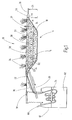
- FIG. 1 shows a capillary system 10 not according to the invention comprising a water storage reservoir 12 and a water-impermeable trough 14 with a height H.
- the water-impermeable trough 14 is formed by a trough bottom 16 and a circumferential side wall 18, which is formed from a 1.2 mm thick PE film become.
- the height H is 0.60 m.
- the tank bottom 16 is opposite an opening 20.
- the entire impermeable tank 14 is filled with an organic or inorganic substrate 28 with capillary action, such as gravel with a grain size of 2 to 8 mm.
- the filling height FH of the water-impermeable trough 14 with the gravel is 0.80 m.
- marsh plants 34 are planted. At mid-latitudes, rushes are particularly suitable as shore or marsh plants.
- the water reservoir 12 is connected via a water supply 22 having a means 24 for generating or maintaining a water supply, and connected via an overflow protection 26 with the water-impermeable trough 14.
- Waste water 64, purified wastewater and / or rainwater 62 are located in the water storage reservoir 12.
- Water 62, 64 is supplied continuously or at intervals through a water inlet 66.
- the water supply flow maintaining means 24 is a clear water pump with pressure hose.
- the water return through the overflow protection 26 takes place automatically due to a gradient.
- the water supply 22 is configured as a drainage pipe 30, which is laid with a distance D2 in the vicinity of the tub bottom 16. The distance D2 to the tub bottom 16 is here about 10 cm.
- the drainage pipe 30 is a PE pipe with a diameter of 100 mm and regularly arranged water outlet openings.
- the purified waste water 62 can thus pass into the gravel 28 and rise from there by means of the capillary forces as moisture in the soil matrix.
- a breather 32 is arranged, which is filled with wood chips. The breather 32 allows a bubble-free filling of the drainage pipe 30th By the wood chips odors are avoided.
- the overflow protection 26 is also a PE pipe with a diameter of 100 mm.
- the distance D3 from the tub bottom 16 to the overflow protection 26 is about 0.50 m.
- the water-impermeable trough 14 and the water reservoir 12 are disposed below the ground level edge 38, d. H. they are completely surrounded by soil 36.
- the distance D1 from the tub bottom 16 to the top edge 38 is 0.70 m.
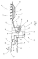
- FIG. 2 shows a capillary system 10 not according to the invention as part of a sewage treatment plant.
- Wastewater 64 is passed through a water inlet 66 into a mud pool 40 of an SBR system 42.
- Solids 52 settle at the bottom of the sludge tank 40 and are transferred by means of a solids pump 48 into a separator 46.
- a separator 46 At the bottom of the separator 46 thus creates a kind of solid filter, is seeped through the still contained in the solids 52 wastewater 64 and pre-cleaned.
- Outgassing gases from the waste water 64 are removed from the separator 46 via a biofluid filter 60.
- the solids 52 are removed as needed from the separator 46, transferred to a thermo-composter 50 and recycled there.
- Waste water 64 from separator 46 is returned to sludge basin 40.
- a level gauge 58 monitors the level in the mud pool 40 to prevent overflow of the mud pool 40.
- the aqueous supernatant in the sludge tank 40 is pumped by means of a clear water pump 24a into an SBR basin 44 in which a biological purification takes place, so that purified waste water 62 is formed.
- the clear water pump 24 b the purified waste water 62 is transferred into the water-impermeable trough 14 of the capillary system 10.
- the overflow protection 26 leads back into the mud basin 40.
- FIG. 3 shows the treatment plant in the supervision.
- the reference numbers apply analogously.
- the water-impermeable trough 14 is configured as a quadrangle and the drainage pipe 30 is also laid as a quadrangle.
- the breather 32 is located opposite the water supply 22.
- the capillary system 10 comprises an area of about 2 m 2 / person. The planting with rushes 34 took place beyond the area of the capillary system 10.
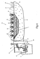
- FIG. 4 shows a capillary system 10 according to the invention with a double bottom, ie with an additional water-impermeable well 15. Reference numerals apply analogously as in FIG. 1 , Only the differences are described in detail.
- the additional water-impermeable tub 15 is formed by a tub bottom 17 and a circumferential side wall 19, wherein the bottom and side walls are formed from a 1.2 mm thick PE film.
- the height of the additional tray 15 is 0.9 m.
- the tub bottom 17 opposite is an opening 21.
- the water-impermeable tray 14 is arranged.
- the remaining volume of the additional tub 15 is filled with permeable soil 36 for horizontal or vertical insurance in the soil matrix.
- shore or marsh plants 34 are planted. At mid-latitudes, rushes are particularly suitable as shore or marsh plants.
- a closable drain 27 leads from the side wall 19 to a collection and inspection shaft 29 and from there back into the water reservoir 12.
- the closable drain 27 is a PE pipe with a diameter of 100 mm.
- the collection and inspection shaft 29 is a PE plastic container with a lid with a volume of 1 m 3 .
- the drain 27 is connected to the collection and inspection shaft 29 and the water reservoir 12 so that water automatically flows through a slope first into the collection and inspection shaft 29 and then into the water reservoir 12. Hygienically safe service water can also be taken from the collection and inspection shaft.
- a drainage-free ROTA collection pit (DIBT No. Z 40.24-286) with integrated technology for composting and sanitizing the high-solids was equipped with a capillary system for the evaporation of highly purified water Wastewater combined. This treatment plant was used to determine the operation in test mode and corresponds to that in the Figures 2 and 3 shown type of plant.
- the nitrate content in the course of the plant could be significantly reduced over time and is at the end of the test at less than 1 mg / l.
- the nitrite content is also less than 1 mg / l.
- the total nitrogen content in the effluent could be reduced over time from 110 mg / l to 85 mg / l, but is still increased due to an increased residual ammonium content. Since the biodegradation processes develop only in the course of time, experience has shown that the full power of biodegradation can only be achieved after approximately 6 months of operation. It is therefore to be expected that biodegradation in the sewage treatment plant will continue to improve over time and that it will be possible to lower the residual ammonium or total nitrogen content below the limit.
- the average water consumption in the plant was about 0.2 m 3 / d. Since the water level in the water-impermeable tub of the capillary system was generally far below the upper edge, no seepage into the subsoil could be detected. At the same time it was noted that since the last sampling no increase in the water level was recorded, but a tie. As a result, the consumption of the purified water was 100% by evaporation or by absorption into the plants or moistening of the surrounding soil.
Landscapes
- Life Sciences & Earth Sciences (AREA)
- Water Supply & Treatment (AREA)
- Engineering & Computer Science (AREA)
- Hydrology & Water Resources (AREA)
- Biodiversity & Conservation Biology (AREA)
- Public Health (AREA)
- Health & Medical Sciences (AREA)
- Microbiology (AREA)
- Environmental & Geological Engineering (AREA)
- Chemical & Material Sciences (AREA)
- Organic Chemistry (AREA)
- Treatment Of Biological Wastes In General (AREA)
- Hydroponics (AREA)
- Purification Treatments By Anaerobic Or Anaerobic And Aerobic Bacteria Or Animals (AREA)
- Heat Treatment Of Water, Waste Water Or Sewage (AREA)
Priority Applications (1)
| Application Number | Priority Date | Filing Date | Title |
|---|---|---|---|
| PL10160124T PL2248770T3 (pl) | 2009-04-16 | 2010-04-16 | Instalacja kapilarna i zastosowanie instalacji kapilarnej w oczyszczalniach ścieków domowych |
Applications Claiming Priority (1)
| Application Number | Priority Date | Filing Date | Title |
|---|---|---|---|
| DE200910017923 DE102009017923A1 (de) | 2009-04-16 | 2009-04-16 | Kapillar-Wasserverteiler und dessen Verwendung in Kläranlagen für häusliches Abwasser |
Publications (3)
| Publication Number | Publication Date |
|---|---|
| EP2248770A2 EP2248770A2 (de) | 2010-11-10 |
| EP2248770A3 EP2248770A3 (de) | 2010-12-15 |
| EP2248770B1 true EP2248770B1 (de) | 2015-09-23 |
Family
ID=42779593
Family Applications (1)
| Application Number | Title | Priority Date | Filing Date |
|---|---|---|---|
| EP10160124.3A Not-in-force EP2248770B1 (de) | 2009-04-16 | 2010-04-16 | Kapillar-Wasserverteiler und dessen Verwendung in Kläranlagen für häusliches Abwasser |
Country Status (5)
| Country | Link |
|---|---|
| EP (1) | EP2248770B1 (pl) |
| DE (1) | DE102009017923A1 (pl) |
| ES (1) | ES2557312T3 (pl) |
| PL (1) | PL2248770T3 (pl) |
| PT (1) | PT2248770E (pl) |
Cited By (2)
| Publication number | Priority date | Publication date | Assignee | Title |
|---|---|---|---|---|
| CN108915061A (zh) * | 2018-07-09 | 2018-11-30 | 高瓴环境科技有限公司 | 农村住宅雨水回收再利用装置 |
| CN110629862A (zh) * | 2019-08-28 | 2019-12-31 | 武汉中能华源设计咨询有限公司 | 一种适用于海绵城市的雨水处理系统 |
Families Citing this family (17)
| Publication number | Priority date | Publication date | Assignee | Title |
|---|---|---|---|---|
| CN102276110B (zh) * | 2011-06-08 | 2012-10-17 | 重庆大学 | 一种修复微污染水体的方法及潜流人工湿地系统 |
| CN103979736B (zh) * | 2014-05-21 | 2015-10-28 | 南京大学 | 低污染水脱氮的人工湿地装置及其处理方法 |
| CN105862967A (zh) * | 2016-05-11 | 2016-08-17 | 广州城建职业学院 | 适用于城市绿地的雨水蓄水回渗模块和系统 |
| CN106171616A (zh) * | 2016-08-30 | 2016-12-07 | 北京东方园林生态股份有限公司 | 一种净化回用的排水种植穴结构 |
| CN108739313A (zh) * | 2018-07-04 | 2018-11-06 | 甘肃中医药大学 | 一种旱地富集雨水系统 |
| CN108867810B (zh) * | 2018-08-07 | 2023-11-07 | 中国科学院南京地理与湖泊研究所 | 一种茶园坡地面源污染控制系统 |
| CN109944312B (zh) * | 2019-03-06 | 2020-07-31 | 南京工业大学 | 一种用于海绵城市建设的浮动滗水式生态雨水调蓄池 |
| NL2022757B1 (en) * | 2019-03-18 | 2020-09-25 | Drainblock B V | Water reservoir system, method of storing water and use thereof therein |
| CN109970214A (zh) * | 2019-04-10 | 2019-07-05 | 清华大学 | 一种具有渗、滞、蓄、净、用、排功能的生物滞留池 |
| CN110206094B (zh) * | 2019-06-04 | 2021-01-12 | 徐州工程学院 | 一种适用于季风性气候的雨水花园系统 |
| CN111656999A (zh) * | 2020-05-26 | 2020-09-15 | 重庆大学 | 一种具有雨水净化和浇灌系统的装配式生态挡墙 |
| CN112431280B (zh) * | 2020-12-23 | 2021-12-24 | 张秋吉 | 一种利用雨水重力排污的城市规划用植物集水设备及使用方法 |
| CN113508741B (zh) * | 2021-04-22 | 2022-08-23 | 赵德旺 | 一种有机废水培育种植植物的方法 |
| CN114651703B (zh) * | 2022-04-06 | 2023-03-24 | 西北农林科技大学 | 果园降水集蓄促渗保墒增碳方法、系统及其果园智能补灌系统 |
| CN115606491B (zh) * | 2022-12-06 | 2023-03-10 | 保定利道交通设施工程有限公司 | 一种园林绿化集水、供水循环净化系统 |
| CN116369159B (zh) * | 2023-05-23 | 2023-12-08 | 贵州师范大学 | 一种石漠化坡面石芽溶沟低碳降水收集灌溉方法 |
| EP4517012A1 (de) * | 2023-08-30 | 2025-03-05 | Lothar Lange GmbH | Unterirdischer retentionsteich und verfahren zur herstellung desselben |
Family Cites Families (11)
| Publication number | Priority date | Publication date | Assignee | Title |
|---|---|---|---|---|
| JPS5515608A (en) * | 1978-07-19 | 1980-02-02 | Doriko Kk | Desert afforesting method |
| US4415450A (en) * | 1981-12-28 | 1983-11-15 | The United States Of America As Represented By The Administrator Of The National Aeronautics And Space Administration | Method for treating wastewater using microorganisms and vascular aquatic plants |
| JPS58131195A (ja) * | 1982-01-30 | 1983-08-04 | Tadashi Niimi | 毛管浸潤トレンチ溝による高雨量高濃度汚水の処理装置 |
| US4824572A (en) * | 1988-04-01 | 1989-04-25 | Scott Richard E | Method and apparatus for treating household waste water |
| DE29618687U1 (de) * | 1996-10-26 | 1996-12-12 | Markgraf, Karl, 38459 Bahrdorf | Anlage zur Abwasserreinigung |
| US5921711A (en) * | 1997-01-23 | 1999-07-13 | Sipaila; Jonas Z. | Subsurface fluid distribution apparatus and method |
| US20030070971A1 (en) * | 2001-10-11 | 2003-04-17 | Kim Jung Yong | Capillary permeation driven pottery pipe trench waste water treatment system |
| FR2837196B1 (fr) * | 2002-03-13 | 2004-07-16 | Ceremher Ct De Rech S Meze Her | Procede et installation pour l'epuration d'effluents domestiques ou agro-industriels par digestion anaerobie |
| DE10330369A1 (de) | 2003-06-30 | 2005-01-20 | Markgraf, Hannelore | Verfahren und Anordnung zur Versickerung von Wasser bei hohem Grundwasserspiegel |
| US7407577B2 (en) * | 2004-09-17 | 2008-08-05 | Curt Kerns | Tertiary filter septic system and method |
| DE102005026644B4 (de) * | 2005-06-09 | 2013-06-06 | Reiner Götz | Verfahren zur Retention von Niederschlagswasser in einer Versickerungsfläche im Gebiet der Entstehung |
-
2009
- 2009-04-16 DE DE200910017923 patent/DE102009017923A1/de not_active Withdrawn
-
2010
- 2010-04-16 EP EP10160124.3A patent/EP2248770B1/de not_active Not-in-force
- 2010-04-16 ES ES10160124.3T patent/ES2557312T3/es active Active
- 2010-04-16 PT PT101601243T patent/PT2248770E/pt unknown
- 2010-04-16 PL PL10160124T patent/PL2248770T3/pl unknown
Cited By (3)
| Publication number | Priority date | Publication date | Assignee | Title |
|---|---|---|---|---|
| CN108915061A (zh) * | 2018-07-09 | 2018-11-30 | 高瓴环境科技有限公司 | 农村住宅雨水回收再利用装置 |
| CN108915061B (zh) * | 2018-07-09 | 2020-07-31 | 高瓴环境科技有限公司 | 农村住宅雨水回收再利用装置 |
| CN110629862A (zh) * | 2019-08-28 | 2019-12-31 | 武汉中能华源设计咨询有限公司 | 一种适用于海绵城市的雨水处理系统 |
Also Published As
| Publication number | Publication date |
|---|---|
| PT2248770E (pt) | 2016-01-20 |
| DE102009017923A1 (de) | 2010-10-28 |
| PL2248770T3 (pl) | 2016-03-31 |
| EP2248770A3 (de) | 2010-12-15 |
| ES2557312T3 (es) | 2016-01-25 |
| EP2248770A2 (de) | 2010-11-10 |
Similar Documents
| Publication | Publication Date | Title |
|---|---|---|
| EP2248770B1 (de) | Kapillar-Wasserverteiler und dessen Verwendung in Kläranlagen für häusliches Abwasser | |
| Brix et al. | The use of vertical flow constructed wetlands for on-site treatment of domestic wastewater: New Danish guidelines | |
| EP2102115B1 (de) | Vertikal-horizontal-filteranlage zur biologischen reinigung von schmutzwässern | |
| CH688623A5 (de) | Verfahren und Anlagen zur Reinigung von Fluessigkeiten in horizontal durchstroemten bepflanzten Filterbetten. | |
| EP0654015A1 (de) | Verfahren und vorrichtung zur biologischen behandlung von organisch belastetem abwasser und organischem abfall. | |
| EP0286582B1 (de) | Anlage zur biologischen Reinigung von Abwasser | |
| CN203440221U (zh) | 用于污泥干化和稳定化处理的人工湿地系统 | |
| DE3244787A1 (de) | Verfahren und vorrichtung zum reinigen von abwaessern | |
| Dodane et al. | Unplanted drying beds | |
| DE202011052232U1 (de) | Abwasserreinigungsanlage mit einem Wurzelraumklärbereich | |
| DE10010109A1 (de) | Kompakt-Bodenfilter-Reaktor | |
| DE102011051932A1 (de) | Abwasserreinigungsanlage mit einem Wurzelraumklärbereich | |
| AT391125B (de) | Anordnung zur reinigung von verunreinigtem wasser | |
| DE60316928T2 (de) | Ausgerüstete pflanzungen zu behandlung von organischen abwässern durch biologische sanierung | |
| DE102012011409A1 (de) | Verfahren zur Wasserbehandlung mit Pflanzenanlagen, sowie Pflanzenanlage (Photobioreaktor) selbst | |
| EP2100856B1 (de) | Verfahren zur mikrobiologischen Behandlung von Wasser aus Gewässern | |
| DE60009509T2 (de) | Verfahren zur reinigung von städtischen, landwirtschaftlichen und/oder industriellen abwässern | |
| EP1519901B1 (de) | Verfahren zur schlammführung aus einer schmutzwasserbehandlungsanlage in einen entwässerungs- und kompostierbehälter und entsprechende schmutzwasserbehandlungsanlage | |
| DE19737542C1 (de) | Bodenfilter zur biologischen Reinigung von vorgeklärtem Abwasser | |
| DE102022105352B4 (de) | System und verfahren zur behandlung und entsorgung von abwasser | |
| DE29707646U1 (de) | Kläranlage zum biologischen Reinigen von organisch belastetem Abwasser | |
| AT9760U1 (de) | Pflanzenkläranlage | |
| AT524488B1 (de) | System und Verfahren zum Entfernen von Nitrat und anderen Verunreinigungen | |
| DE102004048511B4 (de) | Vorrichtung zum Separieren eines Substrats | |
| DE4330422C1 (de) | Verfahren und Anlage zur Entsorgung der Inhalte von Mehrkammer- und Sammelgruben |
Legal Events
| Date | Code | Title | Description |
|---|---|---|---|
| PUAI | Public reference made under article 153(3) epc to a published international application that has entered the european phase |
Free format text: ORIGINAL CODE: 0009012 |
|
| AK | Designated contracting states |
Kind code of ref document: A2 Designated state(s): AT BE BG CH CY CZ DE DK EE ES FI FR GB GR HR HU IE IS IT LI LT LU LV MC MK MT NL NO PL PT RO SE SI SK SM TR |
|
| AX | Request for extension of the european patent |
Extension state: AL BA ME RS |
|
| PUAL | Search report despatched |
Free format text: ORIGINAL CODE: 0009013 |
|
| AK | Designated contracting states |
Kind code of ref document: A3 Designated state(s): AT BE BG CH CY CZ DE DK EE ES FI FR GB GR HR HU IE IS IT LI LT LU LV MC MK MT NL NO PL PT RO SE SI SK SM TR |
|
| AX | Request for extension of the european patent |
Extension state: AL BA ME RS |
|
| RIC1 | Information provided on ipc code assigned before grant |
Ipc: C02F 3/32 20060101ALN20101111BHEP Ipc: E03F 1/00 20060101ALI20101111BHEP Ipc: C02F 3/12 20060101AFI20101006BHEP Ipc: C02F 103/00 20060101ALN20101111BHEP Ipc: C02F 1/00 20060101ALN20101111BHEP |
|
| 17P | Request for examination filed |
Effective date: 20110610 |
|
| GRAP | Despatch of communication of intention to grant a patent |
Free format text: ORIGINAL CODE: EPIDOSNIGR1 |
|
| RIC1 | Information provided on ipc code assigned before grant |
Ipc: E03F 1/00 20060101ALI20150316BHEP Ipc: C02F 3/12 20060101AFI20150316BHEP Ipc: C02F 3/32 20060101ALN20150316BHEP Ipc: C02F 1/00 20060101ALN20150316BHEP Ipc: C02F 103/00 20060101ALN20150316BHEP |
|
| INTG | Intention to grant announced |
Effective date: 20150416 |
|
| GRAS | Grant fee paid |
Free format text: ORIGINAL CODE: EPIDOSNIGR3 |
|
| GRAA | (expected) grant |
Free format text: ORIGINAL CODE: 0009210 |
|
| AK | Designated contracting states |
Kind code of ref document: B1 Designated state(s): AT BE BG CH CY CZ DE DK EE ES FI FR GB GR HR HU IE IS IT LI LT LU LV MC MK MT NL NO PL PT RO SE SI SK SM TR |
|
| REG | Reference to a national code |
Ref country code: GB Ref legal event code: FG4D Free format text: NOT ENGLISH |
|
| REG | Reference to a national code |
Ref country code: CH Ref legal event code: EP |
|
| REG | Reference to a national code |
Ref country code: AT Ref legal event code: REF Ref document number: 751129 Country of ref document: AT Kind code of ref document: T Effective date: 20151015 |
|
| REG | Reference to a national code |
Ref country code: IE Ref legal event code: FG4D Free format text: LANGUAGE OF EP DOCUMENT: GERMAN |
|
| REG | Reference to a national code |
Ref country code: DE Ref legal event code: R096 Ref document number: 502010010345 Country of ref document: DE |
|
| REG | Reference to a national code |
Ref country code: PT Ref legal event code: SC4A Free format text: AVAILABILITY OF NATIONAL TRANSLATION Effective date: 20151207 |
|
| REG | Reference to a national code |
Ref country code: ES Ref legal event code: FG2A Ref document number: 2557312 Country of ref document: ES Kind code of ref document: T3 Effective date: 20160125 |
|
| REG | Reference to a national code |
Ref country code: SE Ref legal event code: TRGR |
|
| REG | Reference to a national code |
Ref country code: NL Ref legal event code: MP Effective date: 20150923 |
|
| PG25 | Lapsed in a contracting state [announced via postgrant information from national office to epo] |
Ref country code: FI Free format text: LAPSE BECAUSE OF FAILURE TO SUBMIT A TRANSLATION OF THE DESCRIPTION OR TO PAY THE FEE WITHIN THE PRESCRIBED TIME-LIMIT Effective date: 20150923 Ref country code: LT Free format text: LAPSE BECAUSE OF FAILURE TO SUBMIT A TRANSLATION OF THE DESCRIPTION OR TO PAY THE FEE WITHIN THE PRESCRIBED TIME-LIMIT Effective date: 20150923 Ref country code: LV Free format text: LAPSE BECAUSE OF FAILURE TO SUBMIT A TRANSLATION OF THE DESCRIPTION OR TO PAY THE FEE WITHIN THE PRESCRIBED TIME-LIMIT Effective date: 20150923 |
|
| REG | Reference to a national code |
Ref country code: LT Ref legal event code: MG4D |
|
| REG | Reference to a national code |
Ref country code: NO Ref legal event code: T2 Effective date: 20150923 |
|
| PG25 | Lapsed in a contracting state [announced via postgrant information from national office to epo] |
Ref country code: HR Free format text: LAPSE BECAUSE OF FAILURE TO SUBMIT A TRANSLATION OF THE DESCRIPTION OR TO PAY THE FEE WITHIN THE PRESCRIBED TIME-LIMIT Effective date: 20150923 |
|
| PG25 | Lapsed in a contracting state [announced via postgrant information from national office to epo] |
Ref country code: NL Free format text: LAPSE BECAUSE OF FAILURE TO SUBMIT A TRANSLATION OF THE DESCRIPTION OR TO PAY THE FEE WITHIN THE PRESCRIBED TIME-LIMIT Effective date: 20150923 |
|
| PG25 | Lapsed in a contracting state [announced via postgrant information from national office to epo] |
Ref country code: IS Free format text: LAPSE BECAUSE OF FAILURE TO SUBMIT A TRANSLATION OF THE DESCRIPTION OR TO PAY THE FEE WITHIN THE PRESCRIBED TIME-LIMIT Effective date: 20160123 Ref country code: EE Free format text: LAPSE BECAUSE OF FAILURE TO SUBMIT A TRANSLATION OF THE DESCRIPTION OR TO PAY THE FEE WITHIN THE PRESCRIBED TIME-LIMIT Effective date: 20150923 Ref country code: SK Free format text: LAPSE BECAUSE OF FAILURE TO SUBMIT A TRANSLATION OF THE DESCRIPTION OR TO PAY THE FEE WITHIN THE PRESCRIBED TIME-LIMIT Effective date: 20150923 Ref country code: CZ Free format text: LAPSE BECAUSE OF FAILURE TO SUBMIT A TRANSLATION OF THE DESCRIPTION OR TO PAY THE FEE WITHIN THE PRESCRIBED TIME-LIMIT Effective date: 20150923 |
|
| PG25 | Lapsed in a contracting state [announced via postgrant information from national office to epo] |
Ref country code: RO Free format text: LAPSE BECAUSE OF FAILURE TO SUBMIT A TRANSLATION OF THE DESCRIPTION OR TO PAY THE FEE WITHIN THE PRESCRIBED TIME-LIMIT Effective date: 20150923 |
|
| REG | Reference to a national code |
Ref country code: GR Ref legal event code: EP Ref document number: 20150402746 Country of ref document: GR Effective date: 20160414 |
|
| REG | Reference to a national code |
Ref country code: DE Ref legal event code: R097 Ref document number: 502010010345 Country of ref document: DE |
|
| PLBE | No opposition filed within time limit |
Free format text: ORIGINAL CODE: 0009261 |
|
| STAA | Information on the status of an ep patent application or granted ep patent |
Free format text: STATUS: NO OPPOSITION FILED WITHIN TIME LIMIT |
|
| 26N | No opposition filed |
Effective date: 20160624 |
|
| PG25 | Lapsed in a contracting state [announced via postgrant information from national office to epo] |
Ref country code: BE Free format text: LAPSE BECAUSE OF NON-PAYMENT OF DUE FEES Effective date: 20160430 Ref country code: DK Free format text: LAPSE BECAUSE OF FAILURE TO SUBMIT A TRANSLATION OF THE DESCRIPTION OR TO PAY THE FEE WITHIN THE PRESCRIBED TIME-LIMIT Effective date: 20150923 |
|
| REG | Reference to a national code |
Ref country code: FR Ref legal event code: PLFP Year of fee payment: 7 |
|
| PG25 | Lapsed in a contracting state [announced via postgrant information from national office to epo] |
Ref country code: SI Free format text: LAPSE BECAUSE OF FAILURE TO SUBMIT A TRANSLATION OF THE DESCRIPTION OR TO PAY THE FEE WITHIN THE PRESCRIBED TIME-LIMIT Effective date: 20150923 |
|
| REG | Reference to a national code |
Ref country code: CH Ref legal event code: PL |
|
| PG25 | Lapsed in a contracting state [announced via postgrant information from national office to epo] |
Ref country code: LU Free format text: LAPSE BECAUSE OF FAILURE TO SUBMIT A TRANSLATION OF THE DESCRIPTION OR TO PAY THE FEE WITHIN THE PRESCRIBED TIME-LIMIT Effective date: 20160416 |
|
| REG | Reference to a national code |
Ref country code: IE Ref legal event code: MM4A |
|
| PG25 | Lapsed in a contracting state [announced via postgrant information from national office to epo] |
Ref country code: CH Free format text: LAPSE BECAUSE OF NON-PAYMENT OF DUE FEES Effective date: 20160430 Ref country code: LI Free format text: LAPSE BECAUSE OF NON-PAYMENT OF DUE FEES Effective date: 20160430 |
|
| PGFP | Annual fee paid to national office [announced via postgrant information from national office to epo] |
Ref country code: TR Payment date: 20161011 Year of fee payment: 7 |
|
| PG25 | Lapsed in a contracting state [announced via postgrant information from national office to epo] |
Ref country code: IE Free format text: LAPSE BECAUSE OF NON-PAYMENT OF DUE FEES Effective date: 20160416 |
|
| REG | Reference to a national code |
Ref country code: FR Ref legal event code: PLFP Year of fee payment: 8 |
|
| PGFP | Annual fee paid to national office [announced via postgrant information from national office to epo] |
Ref country code: PL Payment date: 20171011 Year of fee payment: 8 Ref country code: PT Payment date: 20171016 Year of fee payment: 8 |
|
| PG25 | Lapsed in a contracting state [announced via postgrant information from national office to epo] |
Ref country code: SM Free format text: LAPSE BECAUSE OF FAILURE TO SUBMIT A TRANSLATION OF THE DESCRIPTION OR TO PAY THE FEE WITHIN THE PRESCRIBED TIME-LIMIT Effective date: 20150923 Ref country code: CY Free format text: LAPSE BECAUSE OF FAILURE TO SUBMIT A TRANSLATION OF THE DESCRIPTION OR TO PAY THE FEE WITHIN THE PRESCRIBED TIME-LIMIT Effective date: 20150923 Ref country code: HU Free format text: LAPSE BECAUSE OF FAILURE TO SUBMIT A TRANSLATION OF THE DESCRIPTION OR TO PAY THE FEE WITHIN THE PRESCRIBED TIME-LIMIT; INVALID AB INITIO Effective date: 20100416 |
|
| PG25 | Lapsed in a contracting state [announced via postgrant information from national office to epo] |
Ref country code: MK Free format text: LAPSE BECAUSE OF FAILURE TO SUBMIT A TRANSLATION OF THE DESCRIPTION OR TO PAY THE FEE WITHIN THE PRESCRIBED TIME-LIMIT Effective date: 20150923 Ref country code: MC Free format text: LAPSE BECAUSE OF FAILURE TO SUBMIT A TRANSLATION OF THE DESCRIPTION OR TO PAY THE FEE WITHIN THE PRESCRIBED TIME-LIMIT Effective date: 20150923 Ref country code: MT Free format text: LAPSE BECAUSE OF FAILURE TO SUBMIT A TRANSLATION OF THE DESCRIPTION OR TO PAY THE FEE WITHIN THE PRESCRIBED TIME-LIMIT Effective date: 20150923 |
|
| PG25 | Lapsed in a contracting state [announced via postgrant information from national office to epo] |
Ref country code: BG Free format text: LAPSE BECAUSE OF FAILURE TO SUBMIT A TRANSLATION OF THE DESCRIPTION OR TO PAY THE FEE WITHIN THE PRESCRIBED TIME-LIMIT Effective date: 20150923 |
|
| REG | Reference to a national code |
Ref country code: FR Ref legal event code: PLFP Year of fee payment: 9 |
|
| PG25 | Lapsed in a contracting state [announced via postgrant information from national office to epo] |
Ref country code: PT Free format text: LAPSE BECAUSE OF NON-PAYMENT OF DUE FEES Effective date: 20181016 |
|
| PG25 | Lapsed in a contracting state [announced via postgrant information from national office to epo] |
Ref country code: PL Free format text: LAPSE BECAUSE OF NON-PAYMENT OF DUE FEES Effective date: 20180416 |
|
| PG25 | Lapsed in a contracting state [announced via postgrant information from national office to epo] |
Ref country code: TR Free format text: LAPSE BECAUSE OF NON-PAYMENT OF DUE FEES Effective date: 20170416 |
|
| PGFP | Annual fee paid to national office [announced via postgrant information from national office to epo] |
Ref country code: NO Payment date: 20230519 Year of fee payment: 14 Ref country code: IT Payment date: 20230428 Year of fee payment: 14 Ref country code: FR Payment date: 20230428 Year of fee payment: 14 Ref country code: ES Payment date: 20230517 Year of fee payment: 14 Ref country code: DE Payment date: 20230621 Year of fee payment: 14 |
|
| PGFP | Annual fee paid to national office [announced via postgrant information from national office to epo] |
Ref country code: SE Payment date: 20230427 Year of fee payment: 14 Ref country code: GR Payment date: 20230516 Year of fee payment: 14 Ref country code: AT Payment date: 20230516 Year of fee payment: 14 |
|
| PGFP | Annual fee paid to national office [announced via postgrant information from national office to epo] |
Ref country code: GB Payment date: 20230522 Year of fee payment: 14 |
|
| REG | Reference to a national code |
Ref country code: DE Ref legal event code: R119 Ref document number: 502010010345 Country of ref document: DE |
|
| REG | Reference to a national code |
Ref country code: SE Ref legal event code: EUG |
|
| REG | Reference to a national code |
Ref country code: AT Ref legal event code: MM01 Ref document number: 751129 Country of ref document: AT Kind code of ref document: T Effective date: 20240416 |
|
| GBPC | Gb: european patent ceased through non-payment of renewal fee |
Effective date: 20240416 |
|
| PG25 | Lapsed in a contracting state [announced via postgrant information from national office to epo] |
Ref country code: DE Free format text: LAPSE BECAUSE OF NON-PAYMENT OF DUE FEES Effective date: 20241105 |
|
| PG25 | Lapsed in a contracting state [announced via postgrant information from national office to epo] |
Ref country code: NO Free format text: LAPSE BECAUSE OF NON-PAYMENT OF DUE FEES Effective date: 20240430 |
|
| PG25 | Lapsed in a contracting state [announced via postgrant information from national office to epo] |
Ref country code: GR Free format text: LAPSE BECAUSE OF NON-PAYMENT OF DUE FEES Effective date: 20241104 |
|
| PG25 | Lapsed in a contracting state [announced via postgrant information from national office to epo] |
Ref country code: GB Free format text: LAPSE BECAUSE OF NON-PAYMENT OF DUE FEES Effective date: 20240416 |
|
| PG25 | Lapsed in a contracting state [announced via postgrant information from national office to epo] |
Ref country code: FR Free format text: LAPSE BECAUSE OF NON-PAYMENT OF DUE FEES Effective date: 20240430 |
|
| PG25 | Lapsed in a contracting state [announced via postgrant information from national office to epo] |
Ref country code: AT Free format text: LAPSE BECAUSE OF NON-PAYMENT OF DUE FEES Effective date: 20240416 |
|
| PG25 | Lapsed in a contracting state [announced via postgrant information from national office to epo] |
Ref country code: NO Free format text: LAPSE BECAUSE OF NON-PAYMENT OF DUE FEES Effective date: 20240430 Ref country code: GR Free format text: LAPSE BECAUSE OF NON-PAYMENT OF DUE FEES Effective date: 20241104 Ref country code: GB Free format text: LAPSE BECAUSE OF NON-PAYMENT OF DUE FEES Effective date: 20240416 Ref country code: FR Free format text: LAPSE BECAUSE OF NON-PAYMENT OF DUE FEES Effective date: 20240430 Ref country code: DE Free format text: LAPSE BECAUSE OF NON-PAYMENT OF DUE FEES Effective date: 20241105 Ref country code: AT Free format text: LAPSE BECAUSE OF NON-PAYMENT OF DUE FEES Effective date: 20240416 |
|
| PG25 | Lapsed in a contracting state [announced via postgrant information from national office to epo] |
Ref country code: IT Free format text: LAPSE BECAUSE OF NON-PAYMENT OF DUE FEES Effective date: 20240416 |
|
| REG | Reference to a national code |
Ref country code: ES Ref legal event code: FD2A Effective date: 20250529 |
|
| PG25 | Lapsed in a contracting state [announced via postgrant information from national office to epo] |
Ref country code: ES Free format text: LAPSE BECAUSE OF NON-PAYMENT OF DUE FEES Effective date: 20240417 |
|
| PG25 | Lapsed in a contracting state [announced via postgrant information from national office to epo] |
Ref country code: SE Free format text: LAPSE BECAUSE OF NON-PAYMENT OF DUE FEES Effective date: 20240417 |