EP2248770B1 - Capillary water distributor and use of same in purification assemblies for domestic waste water - Google Patents
Capillary water distributor and use of same in purification assemblies for domestic waste water Download PDFInfo
- Publication number
- EP2248770B1 EP2248770B1 EP10160124.3A EP10160124A EP2248770B1 EP 2248770 B1 EP2248770 B1 EP 2248770B1 EP 10160124 A EP10160124 A EP 10160124A EP 2248770 B1 EP2248770 B1 EP 2248770B1
- Authority
- EP
- European Patent Office
- Prior art keywords
- water
- trough
- capillary
- watertight
- plant
- Prior art date
- Legal status (The legal status is an assumption and is not a legal conclusion. Google has not performed a legal analysis and makes no representation as to the accuracy of the status listed.)
- Not-in-force
Links
Images

Classifications
-
- E—FIXED CONSTRUCTIONS
- E03—WATER SUPPLY; SEWERAGE
- E03F—SEWERS; CESSPOOLS
- E03F1/00—Methods, systems, or installations for draining-off sewage or storm water
- E03F1/002—Methods, systems, or installations for draining-off sewage or storm water with disposal into the ground, e.g. via dry wells
-
- C—CHEMISTRY; METALLURGY
- C02—TREATMENT OF WATER, WASTE WATER, SEWAGE, OR SLUDGE
- C02F—TREATMENT OF WATER, WASTE WATER, SEWAGE, OR SLUDGE
- C02F3/00—Biological treatment of water, waste water, or sewage
- C02F3/02—Aerobic processes
- C02F3/12—Activated sludge processes
- C02F3/1236—Particular type of activated sludge installations
- C02F3/1242—Small compact installations for use in homes, apartment blocks, hotels or the like
-
- C—CHEMISTRY; METALLURGY
- C02—TREATMENT OF WATER, WASTE WATER, SEWAGE, OR SLUDGE
- C02F—TREATMENT OF WATER, WASTE WATER, SEWAGE, OR SLUDGE
- C02F1/00—Treatment of water, waste water, or sewage
- C02F1/006—Water distributors either inside a treatment tank or directing the water to several treatment tanks; Water treatment plants incorporating these distributors, with or without chemical or biological tanks
-
- C—CHEMISTRY; METALLURGY
- C02—TREATMENT OF WATER, WASTE WATER, SEWAGE, OR SLUDGE
- C02F—TREATMENT OF WATER, WASTE WATER, SEWAGE, OR SLUDGE
- C02F2103/00—Nature of the water, waste water, sewage or sludge to be treated
- C02F2103/001—Runoff or storm water
-
- C—CHEMISTRY; METALLURGY
- C02—TREATMENT OF WATER, WASTE WATER, SEWAGE, OR SLUDGE
- C02F—TREATMENT OF WATER, WASTE WATER, SEWAGE, OR SLUDGE
- C02F2103/00—Nature of the water, waste water, sewage or sludge to be treated
- C02F2103/002—Grey water, e.g. from clothes washers, showers or dishwashers
-
- C—CHEMISTRY; METALLURGY
- C02—TREATMENT OF WATER, WASTE WATER, SEWAGE, OR SLUDGE
- C02F—TREATMENT OF WATER, WASTE WATER, SEWAGE, OR SLUDGE
- C02F3/00—Biological treatment of water, waste water, or sewage
- C02F3/02—Aerobic processes
- C02F3/12—Activated sludge processes
- C02F3/1236—Particular type of activated sludge installations
- C02F3/1263—Sequencing batch reactors [SBR]
-
- C—CHEMISTRY; METALLURGY
- C02—TREATMENT OF WATER, WASTE WATER, SEWAGE, OR SLUDGE
- C02F—TREATMENT OF WATER, WASTE WATER, SEWAGE, OR SLUDGE
- C02F3/00—Biological treatment of water, waste water, or sewage
- C02F3/32—Biological treatment of water, waste water, or sewage characterised by the animals or plants used, e.g. algae
- C02F3/327—Biological treatment of water, waste water, or sewage characterised by the animals or plants used, e.g. algae characterised by animals and plants
-
- Y—GENERAL TAGGING OF NEW TECHNOLOGICAL DEVELOPMENTS; GENERAL TAGGING OF CROSS-SECTIONAL TECHNOLOGIES SPANNING OVER SEVERAL SECTIONS OF THE IPC; TECHNICAL SUBJECTS COVERED BY FORMER USPC CROSS-REFERENCE ART COLLECTIONS [XRACs] AND DIGESTS
- Y02—TECHNOLOGIES OR APPLICATIONS FOR MITIGATION OR ADAPTATION AGAINST CLIMATE CHANGE
- Y02W—CLIMATE CHANGE MITIGATION TECHNOLOGIES RELATED TO WASTEWATER TREATMENT OR WASTE MANAGEMENT
- Y02W10/00—Technologies for wastewater treatment
- Y02W10/10—Biological treatment of water, waste water, or sewage
Definitions
- the invention relates to a capillary system and its use in sewage treatment plants for domestic wastewater. Furthermore, the invention relates to a method for sewage and / or rainwater treatment in which the wastewater is collected, optionally prepurified and then cleaned the prepurified water by means of a capillary system according to the invention, evaporated and / or released as moisture to the surrounding soil rich and / or Plant irrigation and hot water use is used. According to the invention, the receiving water and / or a device for infiltration of the clear water into macropores can thereby be eliminated, which is particularly necessary in regions with sensitive waters.
- the utilization of the purified waste water on site is particularly advantageous from an ecological as well as an economic point of view and corresponds to the Requirements of the international Agenda 21, to close water and raw material cycles as locally as possible.
- Purified wastewater and / or service water should therefore be reused for the formation of groundwater on site.
- the DE 103 30 369 A1 proposes, therefore, to increase the top surface of the terrain by means of local fillings so that the groundwater level is permanently lower than approximately 1.20 m below the ground level so that infiltration is possible again.
- landfills are always an intervention in landscaping and therefore can not be used nationwide.
- the increase in soil level is very material intensive and is only in question if surpluses, such as waste dumps or the like, are available.
- the font JP 55015608 A discloses a water treatment tank connected to a treatment tank 6 via a distribution chamber 1.
- the pretreated water is introduced via a perforated tube 11 into the lower third of the container 6, which is filled with water-permeable layers of gravel and sand.
- a further perforated tube is arranged, which opens above the water level WL in the distribution chamber 1.
- the invention accordingly relates to a capillary system which has at least one water reservoir, at least one water-impermeable well with a specific height, at least one water feed, the means for generating and / or maintaining a flow of water from the at least one water reservoir into the at least one water-impermeable well, at least one overflow protection that watertight connects the at least one water-impermeable tub with the at least one water reservoir, and at least one organic and / or inorganic substrate, which is arranged in the at least one water-impermeable tub and has a capillary action, wherein the capillary system so in Soil can be arranged that the tub bottom the ground surface of the ground opposite and the distance from the bottom of the tank to the ground level is equal to or greater than the height of the water-impermeable tub.
- any container can be used as a water reservoir according to the invention.
- Exemplary containers are made of stainless steel or plastic, e.g. Polyethylene (PE), polypropylene (PP) or polytetrafluoroethylene (PTFE) manufactured. Other suitable materials for water storage tanks are known in the art.
- the water reservoir according to the invention may be a single container or part of an upstream treatment plant. In a preferred embodiment of the invention, the water reservoir on rainwater and / or purified wastewater or clear water.
- the at least one water-impermeable trough comprises a trough bottom, a circumferential side wall or a plurality of side walls and an opening, which is a surface opposite the trough bottom and through the upper, i. the edge facing away from the tub bottom of the peripheral side wall is limited.
- the height of the water-impermeable tub extends from the bottom of the tub to the opening.
- the tank bottom can be configured in any desired shape, preferably round, elliptical or polygonal.
- the water-impermeable trough according to the invention has one circumferential or several adjoining side walls. If there are several side walls, they are preferably the same height.
- the angle between the tub bottom and the peripheral side wall is an obtuse angle. This means that water-impermeable troughs are preferred in which the opening of the trough is larger than the trough bottom.
- the water-impermeable tub according to the invention preferably consists of stainless steel or plastic, such as PE, PP or PTFE, particularly preferably PE.
- suitable materials are known to the person skilled in the art.
- the material thickness of the water-impermeable trough is preferably chosen such that, despite possibly in the soil befind Anlagen stones or similar pointed objects, there is no risk of leaks, cracks and / or holes. Material thicknesses of at least 1 mm, preferably at least 1.2 mm are sufficient according to the invention. To form the water-impermeable well, therefore, can also from the films suitable materials are used in the intended strength, with which a suitable depression in the ground is designed.
- the height of the water-impermeable trough 0.1 to 3 m, preferably 0.5 to 1.5 m.
- the diameter of the water-impermeable tub or its opening can be designed variably and is adapted to the amount of water to be cleaned and evaporated. Typical area sizes are in the range of 1 to 500 m 2 , preferably in the range of 5 to 100 m 2 , more preferably in the range of 10 to 20 m 2 .
- the at least one water supply is arranged according to the invention such that the distance of the water supply to the tank bottom is a maximum ofillon the height of the water-impermeable trough.
- the water supply is arranged as close as possible to the tank bottom and the water supply thus takes place from below.
- the water applied to the bottom of the tank then rises according to the invention as moisture mediated by the capillary forces of the inorganic and / or organic substrate in the water-impermeable tank.
- the water supply can be arranged in the at least one side wall or in the tank bottom.
- the water supply is a drainage pipe, which is preferably arranged parallel to the tub bottom.
- the drainage tube is thereby guided either through the side wall or through the opening of the water-impermeable trough in this.
- the drainage pipe according to the invention is guided as close as possible to the bottom of the tank and over the entire surface of the tank bottom.
- a long drainage pipe which is laid in loops, as well as a plurality of drainage pipes, which branch off from a central water supply, are provided. Suitable embodiments are known to the person skilled in the art.
- the drainage tube according to the invention is preferably made of stainless steel or plastic, e.g. PE, PP or PTFE, more preferably PE.
- the drainage pipe has at least one loading and / or deaerating.
- This is preferably a cylinder that connects the drainage pipe with the ambient air.
- the ventilator is arranged perpendicular to the drainage pipe. By means of the ventilator, gases still present in the treated wastewater can escape. moreover The wastewater comes into contact with oxygen and transfers it together with the wastewater into the substrate present in the water-impermeable tank.
- the ventilator is equipped with a filter, preferably a biofilter.
- a filter preferably a biofilter.
- the breather and / or deaerator has means for absorbing and / or decomposing organic and / or inorganic gases, preferably activated carbon, burl wood chips, wood chips and / or microorganisms.
- Further suitable filter materials are known to the person skilled in the art. If microorganisms are used to break down organic and / or inorganic gases, it is important that the filters do not dry out.
- the filter material is preferably a material with a large water storage capacity or it has wicks that moisten the filter from the drainage pipe with water.
- the capillary system further comprises an overflow protection, which connects the water-impermeable tank with the water reservoir.
- the overflow protection is arranged in the upper region of the water-impermeable trough.
- the distance of the overflow protection to the tank bottom is at least 2/3 of the height of the water-impermeable tank. More preferably, the distance of the overflow protection to the tank bottom is a maximum of 95%, more preferably a maximum of 90%, more preferably a maximum of 80% of the height of the water-impermeable tank.
- the overflow protection regulates the maximum level of the water-impermeable tub and prevents overflow.
- the water-impermeable tub is filled to about 50 to 60%, in burst mode or overloading excess water is transferred through the overflow protection in the water reservoir.
- overflow protection any tube or hose can be used.
- waterproof tub and water reservoir are arranged so that the overflow protection has a slight slope and the water automatically flows back into the water reservoir.
- means for actively transporting the water such as a pump, can also be provided in the overflow protection.
- the part of the overflow protection that reaches into the water-impermeable tub is closed with a filter or a sieve, so that solid components, such as the substrate, are retained, and only the water runs through the overflow protection.
- the water-impermeable tub according to the invention is filled with an organic and / or inorganic substrate, which according to the invention has a capillary action.
- an ascending capillary pressure is generated in the impermeable tub. This ensures that the liquid water present exclusively in the lower region of the water-impermeable trough rises as moisture in the substrate, that is to say in the soil matrix, and thus reaches the surface or near the roots of the plants to be watered.
- the rising damp can also be delivered to the soil surrounding the water-impermeable tank or the soil surrounding the tank.
- textile wicks preferably of natural fibers, synthetic fibers and / or glass fibers, may additionally or alternatively be provided in the organic and / or inorganic substrate, which additionally exert a capillary action or reinforce it.
- the organic and / or inorganic capillary substrate preferably comprises sand, gravel, gravel, clay, expanded clay, lava, textile fabric mats consisting of natural fibers, plastic fibers and / or glass fibers, a mixture thereof and / or a mixture with those above called wicks.
- the particle size or particle size of the organic and / or inorganic substrate is preferably in the range from 0.2 to 20 mm, more preferably in the range from 1 to 20 mm, more preferably in the range of 1 to 10 mm, most preferably in the range of 2 to 8 mm.
- the filling level of the organic and / or inorganic substrate in the water-impermeable trough is equal to or greater than the height of the water-impermeable trough.
- the water-impermeable trough is preferably completely filled with the organic and / or inorganic substrate or the substrate projects beyond the upper edge of the side walls.
- the water-impermeable trough can be arranged just deep enough in the topsoil or in the soil that the edges of the side walls terminate with the terrain upper edge.
- the water-impermeable pan is arranged deeper in the ground.
- the filling height is equal to or greater than the distance from the trough floor to the ground level. This means that the organic and / or inorganic substrate is piled up as a kind of bed above the ground level. Furthermore, the organic and / or inorganic substrate can extend laterally beyond the side walls of the water-impermeable trough, so that a transition from the organic and / or inorganic substrate to the surrounding soil is formed.
- an additional second or further water-impermeable trough is arranged below the water-impermeable trough, ie deeper in the ground.
- This second tub also has a tub bottom, at least one circumferential side wall and an opening, wherein the opening is a surface opposite the tub bottom and is limited by the tub bottom opposite edge of the at least one circumferential side wall.
- the volume of the additional water-impermeable trough is greater than the volume of the first water-impermeable trough.
- the second additional water-impermeable tub is placed in the ground such that the first water-impermeable tub is arranged in the second water-impermeable tub and the openings of the two tubs are positioned at the ground level.
- the additional water-impermeable pan represents a further delimitation of the surrounding soil from the environment, in particular with respect to the groundwater.
- the first water-impermeable pan is also against overflowing or secured against leaks in the floor or wall area.
- the rising in the soil matrix through the capillary forces moisture does not pass directly into the unsecured soil, but is collected again in an additional separated area of the soil. This is particularly advantageous if due to a high utilization of the system from the moisture after rising in the first water-impermeable tub and passage into the surrounding soil by saturation in the surrounding soil again water droplets should form, which could otherwise seep.
- the capillary system according to the invention is thus equipped with a double bottom and therefore advantageously satisfies the legal requirements.
- the further second water-impermeable trough is preferably made of the same materials as the first water-impermeable trough according to the invention.
- plastic films, more preferably PE films are used to form the additional water-impermeable pan, with which a suitable depression in the ground is designed.
- the additional water-impermeable tub has a larger volume than the first water-impermeable tub.
- the trough bottom of the second water-impermeable trough is clear, i. preferably increased by a factor of 1.2 to 5, particularly preferably by a factor of 1.2 to 2.
- the height of the second water-impermeable trough is preferably only slightly increased in order to be able to use the capillary system according to the invention even when the groundwater is high.
- the volume of the second water-impermeable well, which is not occupied by the first water-impermeable pan, is preferably filled with the sand surrounding the capillary system or the surrounding soil.
- the additional water-impermeable trough on a closable drain is preferably arranged in the region of the tank bottom and connects the additional water-impermeable tank waterproof with the water reservoir. If it comes to a formation of water droplets by saturation of the soil in the additional water-impermeable tub, this is discharged through the drain and directed back into the water reservoir. Thus, moisture, which precipitates again as water, are fed back into the capillary circulation.
- any tube or hose can be used.
- the additional water-impermeable tub and the water reservoir arranged such that the drain has a slight slope and the water automatically flows back into the water reservoir.
- the closable drain additionally has a filter or a sieve, so that solid components, such as the soil, are retained.
- the closable drain is connected watertight to a collection and / or inspection shaft.
- a collecting and / or inspection shaft according to the invention a container understood, which is also embedded in the ground and accessible from the top of the terrain. From the collection and / or inspection shaft water samples can be taken and fed to an analysis. Hygienically safe, collected in the collection and / or inspection shaft water can then be a normal receiving water or a process water recovery, for example, in the toilet flush, fed.
- the collection and / or inspection shaft is connected to the water reservoir, so that overflow is prevented and excess water is supplied to the capillary cycle again.
- the organic and / or inorganic substrate bank plants (littoral Helophyten) and / or marsh plants (Helophyten), preferably reed plants (Arundophyten), Sauergrasgewentese (Cyperaceae) and / or rushes (Juncaceae), even more preferably rushes ( Juncus), up.
- the soil arranged in the second water-impermeable tank is also overgrown with said bank plants and / or marsh plants.
- the capillary plant is arranged in the ground, that the bottom of the first water-impermeable tub and the additional second water-impermeable tub are arranged opposite to the ground surface of the soil and the distance from the bottom of the first water-impermeable tub to the ground level or equal greater than the height of the first water-impermeable tub.
- the first water-impermeable tank can be flush with the ground level or completely covered by soil.
- the water-impermeable trough can be arranged deeper in the ground, so that over the trough opening still a layer of soil is arranged.
- the preferred distance between the tub bottom and the ground level is a maximum of 30 cm, preferably a maximum of 20 cm, more preferably 5 to 10 cm greater than the height of the water-impermeable tub.
- this is preferably arranged so deep in the ground that the edges of their side surfaces and their opening complete with the ground level.
- the capillary system is in the soil, i. arranged in the topsoil of an outdoor area.
- the soil of a greenhouse or a comparable plant breeding building is in the soil, i. arranged in the topsoil of an outdoor area.
- the invention further relates to a sewage treatment plant having at least one capillary plant of the invention.
- the capillary system according to the invention can be used instead of a receiving water in municipal sewage treatment plants.
- the sewage treatment plant which has a capillary plant according to the invention, is a micro sewage treatment plant with a maximum wastewater volume of 8 m 3 / d or a small sewage treatment plant with a sewage volume of 8 to 800 m 3 / d.
- This corresponds to a population of approx. 50 inhabitants connected to the wastewater treatment plant at the micro sewage treatment plant or 50 - 5000 inhabitants at the small sewage treatment plant.
- the capillary system according to the invention replaced in this arrangement, the Verrieselungs vom.
- the invention is thus preferably used both on land of single-family homes and / or cottages as well as for incurred in larger buildings and / or housing complexes wastewater.
- the capillary system according to the invention can also be used in other collection or storage units and / or water treatment plants and / or retrofitted.
- collected rainwater such as rainwater collected from roof surfaces or water collected on other, at least partially water impermeable surfaces and treated as needed, may be used in the capillary system according to the invention.
- the treatment plant comprises a drainage-free collection pit for domestic wastewater and / or a system for sequential biological purification (SBR system), a means for composting the thick matter, preferably a thermal composter, and a capillary system according to the invention.
- SBR system sequential biological purification
- the drainage-free sump and / or the SBR basin of the SBR system is the water reservoir of the capillary system.
- a drainage-free collection pit is a container used to collect and store domestic wastewater. The disposal takes place depending on the amount of sewage once or twice a year. In the standing waste water, however, settle the solids, so that a pre-cleaning takes place and the supernatant water can be transferred to a capillary system according to the invention.
- a sewage treatment plant according to the invention preferably has an SBR system.
- This is a two-stage system.
- the first basin i. the mud reservoir fulfills similar functions as a drainage-free collection pit.
- the second basin the actual SBR basin takes place intermittently a biological purification of the supernatant water from the mud reservoir.
- the thus prepurified water can be used in the capillary system according to the invention.
- the solids are preferably pumped out regularly and utilized in a means for composting the thick matter, preferably a thermal composter, also on site. A rapid infiltration into the groundwater can thus be permanently eliminated by the use of the sewage treatment plant according to the invention.
- the capillary system according to the invention can furthermore be combined with all other sewage treatment plants known to the person skilled in the art and / or plants for the pre-purification of wastewater, such as, for example, sewage treatment plants, fixed bed sewage treatment plants, installations for the mechanical pre-purification of pond installations.
- the invention further relates to a process for the purification of wastewater, purified wastewater and / or rainwater, wherein the wastewater, purified wastewater and / or rainwater is collected and collected, optionally mechanically and / or biologically pre-cleaned, fed to the water reservoir of a capillary system according to the invention is transferred, and in the water-impermeable tub of the capillary system.
- the wastewater, purified wastewater and / or rainwater rises in the water-impermeable tub of the capillary system according to the invention by capillary forces and is discharged as purified water, purified water vapor and / or water vapor to the surrounding air and / or as purified moisture to the surrounding soil or used for irrigation of plants or as process water.
- the moisture escaping from the capillary system is hygienically harmless.
- the invention thus relates to a method for sanitizing water and / or wastewater.
- the wastewater, purified wastewater and / or rainwater in the first and / or second purification stage of a municipal sewage treatment plant is mechanically and / or biologically pre-cleaned.
- the pre-cleaning of the waste water corresponds to the cleaning in a small sewage treatment plant, the cleaning in a micro-wastewater treatment plant and / or the cleaning in a drainage-free collecting pit.
- the water-impermeable tub of the capillary system according to the invention is preferably fed continuously or at intervals with wastewater, purified wastewater and / or rainwater.
- the water purified according to the invention is used as ascending moisture for irrigating the plants growing on the organic and / or inorganic substrate or as process water.
- the substrate of the capillary system according to the invention into the topsoil of the surrounding soil, plants can also be supplied with moisture on surfaces adjacent to the capillary system.
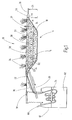
- FIG. 1 shows a capillary system 10 not according to the invention comprising a water storage reservoir 12 and a water-impermeable trough 14 with a height H.
- the water-impermeable trough 14 is formed by a trough bottom 16 and a circumferential side wall 18, which is formed from a 1.2 mm thick PE film become.
- the height H is 0.60 m.
- the tank bottom 16 is opposite an opening 20.
- the entire impermeable tank 14 is filled with an organic or inorganic substrate 28 with capillary action, such as gravel with a grain size of 2 to 8 mm.
- the filling height FH of the water-impermeable trough 14 with the gravel is 0.80 m.
- marsh plants 34 are planted. At mid-latitudes, rushes are particularly suitable as shore or marsh plants.
- the water reservoir 12 is connected via a water supply 22 having a means 24 for generating or maintaining a water supply, and connected via an overflow protection 26 with the water-impermeable trough 14.
- Waste water 64, purified wastewater and / or rainwater 62 are located in the water storage reservoir 12.
- Water 62, 64 is supplied continuously or at intervals through a water inlet 66.
- the water supply flow maintaining means 24 is a clear water pump with pressure hose.
- the water return through the overflow protection 26 takes place automatically due to a gradient.
- the water supply 22 is configured as a drainage pipe 30, which is laid with a distance D2 in the vicinity of the tub bottom 16. The distance D2 to the tub bottom 16 is here about 10 cm.
- the drainage pipe 30 is a PE pipe with a diameter of 100 mm and regularly arranged water outlet openings.
- the purified waste water 62 can thus pass into the gravel 28 and rise from there by means of the capillary forces as moisture in the soil matrix.
- a breather 32 is arranged, which is filled with wood chips. The breather 32 allows a bubble-free filling of the drainage pipe 30th By the wood chips odors are avoided.
- the overflow protection 26 is also a PE pipe with a diameter of 100 mm.
- the distance D3 from the tub bottom 16 to the overflow protection 26 is about 0.50 m.
- the water-impermeable trough 14 and the water reservoir 12 are disposed below the ground level edge 38, d. H. they are completely surrounded by soil 36.
- the distance D1 from the tub bottom 16 to the top edge 38 is 0.70 m.
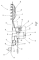
- FIG. 2 shows a capillary system 10 not according to the invention as part of a sewage treatment plant.
- Wastewater 64 is passed through a water inlet 66 into a mud pool 40 of an SBR system 42.
- Solids 52 settle at the bottom of the sludge tank 40 and are transferred by means of a solids pump 48 into a separator 46.
- a separator 46 At the bottom of the separator 46 thus creates a kind of solid filter, is seeped through the still contained in the solids 52 wastewater 64 and pre-cleaned.
- Outgassing gases from the waste water 64 are removed from the separator 46 via a biofluid filter 60.
- the solids 52 are removed as needed from the separator 46, transferred to a thermo-composter 50 and recycled there.
- Waste water 64 from separator 46 is returned to sludge basin 40.
- a level gauge 58 monitors the level in the mud pool 40 to prevent overflow of the mud pool 40.
- the aqueous supernatant in the sludge tank 40 is pumped by means of a clear water pump 24a into an SBR basin 44 in which a biological purification takes place, so that purified waste water 62 is formed.
- the clear water pump 24 b the purified waste water 62 is transferred into the water-impermeable trough 14 of the capillary system 10.
- the overflow protection 26 leads back into the mud basin 40.
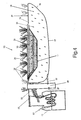
- FIG. 3 shows the treatment plant in the supervision.
- the reference numbers apply analogously.
- the water-impermeable trough 14 is configured as a quadrangle and the drainage pipe 30 is also laid as a quadrangle.
- the breather 32 is located opposite the water supply 22.
- the capillary system 10 comprises an area of about 2 m 2 / person. The planting with rushes 34 took place beyond the area of the capillary system 10.
- FIG. 4 shows a capillary system 10 according to the invention with a double bottom, ie with an additional water-impermeable well 15. Reference numerals apply analogously as in FIG. 1 , Only the differences are described in detail.
- the additional water-impermeable tub 15 is formed by a tub bottom 17 and a circumferential side wall 19, wherein the bottom and side walls are formed from a 1.2 mm thick PE film.
- the height of the additional tray 15 is 0.9 m.
- the tub bottom 17 opposite is an opening 21.
- the water-impermeable tray 14 is arranged.
- the remaining volume of the additional tub 15 is filled with permeable soil 36 for horizontal or vertical insurance in the soil matrix.
- shore or marsh plants 34 are planted. At mid-latitudes, rushes are particularly suitable as shore or marsh plants.
- a closable drain 27 leads from the side wall 19 to a collection and inspection shaft 29 and from there back into the water reservoir 12.
- the closable drain 27 is a PE pipe with a diameter of 100 mm.
- the collection and inspection shaft 29 is a PE plastic container with a lid with a volume of 1 m 3 .
- the drain 27 is connected to the collection and inspection shaft 29 and the water reservoir 12 so that water automatically flows through a slope first into the collection and inspection shaft 29 and then into the water reservoir 12. Hygienically safe service water can also be taken from the collection and inspection shaft.
- a drainage-free ROTA collection pit (DIBT No. Z 40.24-286) with integrated technology for composting and sanitizing the high-solids was equipped with a capillary system for the evaporation of highly purified water Wastewater combined. This treatment plant was used to determine the operation in test mode and corresponds to that in the Figures 2 and 3 shown type of plant.
- the nitrate content in the course of the plant could be significantly reduced over time and is at the end of the test at less than 1 mg / l.
- the nitrite content is also less than 1 mg / l.
- the total nitrogen content in the effluent could be reduced over time from 110 mg / l to 85 mg / l, but is still increased due to an increased residual ammonium content. Since the biodegradation processes develop only in the course of time, experience has shown that the full power of biodegradation can only be achieved after approximately 6 months of operation. It is therefore to be expected that biodegradation in the sewage treatment plant will continue to improve over time and that it will be possible to lower the residual ammonium or total nitrogen content below the limit.
- the average water consumption in the plant was about 0.2 m 3 / d. Since the water level in the water-impermeable tub of the capillary system was generally far below the upper edge, no seepage into the subsoil could be detected. At the same time it was noted that since the last sampling no increase in the water level was recorded, but a tie. As a result, the consumption of the purified water was 100% by evaporation or by absorption into the plants or moistening of the surrounding soil.
Landscapes
- Life Sciences & Earth Sciences (AREA)
- Water Supply & Treatment (AREA)
- Engineering & Computer Science (AREA)
- Hydrology & Water Resources (AREA)
- Organic Chemistry (AREA)
- Environmental & Geological Engineering (AREA)
- Biodiversity & Conservation Biology (AREA)
- Chemical & Material Sciences (AREA)
- Microbiology (AREA)
- Health & Medical Sciences (AREA)
- Public Health (AREA)
- Treatment Of Biological Wastes In General (AREA)
- Heat Treatment Of Water, Waste Water Or Sewage (AREA)
- Hydroponics (AREA)
- Purification Treatments By Anaerobic Or Anaerobic And Aerobic Bacteria Or Animals (AREA)
Description
Die Erfindung betrifft eine Kapillar-Anlage sowie dessen Verwendung in Kläranlagen für häusliches Abwasser. Des Weiteren betrifft die Erfindung ein Verfahren zur Abwasser- und/oder Regenwasseraufbereitung, bei dem das Abwasser gesammelt, optional vorgereinigt und dann das vorgereinigte Wasser mittels einer erfindungsgemäßen Kapillar-Anlage gereinigt, verdunstet und/oder als Feuchtigkeit an das Umgebungserdreich abgegeben und/oder zur Pflanzenbewässerung und Brauchwassernutzung eingesetzt wird. Erfindungsgemäß kann dadurch der Vorfluter und/oder eine Vorrichtung zur Versickerung des Klarwassers in Makroporen entfallen, was besonders in Regionen mit sensiblen Gewässern vonnöten ist.The invention relates to a capillary system and its use in sewage treatment plants for domestic wastewater. Furthermore, the invention relates to a method for sewage and / or rainwater treatment in which the wastewater is collected, optionally prepurified and then cleaned the prepurified water by means of a capillary system according to the invention, evaporated and / or released as moisture to the surrounding soil rich and / or Plant irrigation and hot water use is used. According to the invention, the receiving water and / or a device for infiltration of the clear water into macropores can thereby be eliminated, which is particularly necessary in regions with sensitive waters.
In vielen Regionen herrscht zumindest in der warmen trockenen Jahreszeit Wasserknappheit bei teilweise bedenklich sinkendem Grundwasserspiegel. Ursache hierfür ist oft, dass Wasser im ländlichen Raum dezentral, beispielsweise über Brunnen, entnommen wird, aber nach dessen Benutzung zentral, beispielsweise über Rohrleitungen und Kläranlagen in so genannte Vorfluter abgeführt wird. Eine Nutzung und/oder Versickerung des Wassers vor Ort würde ein unerwünschtes Absinken des Grundwasserspiegels reduzieren und zudem das Hochwasser-Aufkommen am Vorfluter verringern.In many regions, at least during the warm, dry seasons, water scarcity prevails, with a sometimes questionable sinking groundwater level. This is often due to the fact that water in rural areas is taken from a decentralized location, for example via wells, but is discharged centrally into the so-called receiving water after its use, for example via pipelines and sewage treatment plants. On-site use and / or infiltration of the water would reduce unwanted sinking of the groundwater table and also reduce flooding of the receiving waters.
Im Bereich der Wasser- bzw. Abwasser-Versickerung und Bodenfiltertechnik sind bisher die horizontalen und vertikalen Bodenfilter bekannt, wo das Wasser horizontal oder vertikal durch das Filtermaterial strömt. Im Bereich der Versickerung von Regenwasser oder gereinigtem Abwasser wird immer vertikal nach unten in Richtung Grundwasser versickert. In sensiblen Regionen, wie Wasserschutzgebieten, Karstgebieten oder in Gebieten mit extrem hohem Grundwasserstand oder bindigen Böden ist eine schnelle Versickerung von gereinigtem Abwasser in Makroporen zum Schutz des Grundwassers nicht sinnvoll.In the field of water or sewage infiltration and soil filtration technology hitherto, the horizontal and vertical soil filters are known where the water flows horizontally or vertically through the filter material. In the area of infiltration of rainwater or purified wastewater, it is always infiltrated vertically downwards in the direction of groundwater. In sensitive regions, such as water conservation areas, karst areas or in areas with extremely high groundwater levels or cohesive soils, rapid seepage of purified wastewater into macropores for the protection of groundwater does not make sense.
Die Verwertung des gereinigten Abwassers vor Ort ist allerdings sowohl aus ökologischer als auch aus ökonomischer Sicht besonders vorteilhaft und entspricht den Anforderungen der internationalen Agenda 21, Wasser- und Rohstoffkreisläufe möglichst lokal zu schließen. Gereinigtes Abwasser und/oder Brauchwasser sollte somit zur Neubildung von Grundwasser vor Ort wiederverwertet werden.However, the utilization of the purified waste water on site is particularly advantageous from an ecological as well as an economic point of view and corresponds to the Requirements of the
Die
Die Schrift
In der Schrift
Es ist die Aufgabe der Erfindung, eine Vorrichtung und ein Verfahren zur Verfügung zu stellen, mit dem gereinigtes, hygienisch unbedenkliches Abwasser und/oder Regenwasser ohne schnelle Versickerung in Makroporen dem lokalen Wasserkreislauf zugeführt wird.It is the object of the invention to provide an apparatus and a method are available, with the purified, hygienic wastewater and / or rainwater is supplied to the local water cycle without rapid seepage into macropores.
Diese Aufgabe wird erfindungsgemäß gelöst durch die Merkmale im kennzeichnenden Teil der Hauptansprüche 1, 12 und 14 im Zusammenwirken mit den Merkmalen im Oberbegriff. Zweckmäßige Ausgestaltungen der Erfindung sind in den Unteransprüchen enthalten.This object is achieved by the features in the characterizing part of the
Die Erfindung betrifft demnach eine Kapillar-Anlage, die mindestens einen Wasservorratsbehälter, mindestens eine wasserundurchlässige Wanne mit einer bestimmten Höhe, mindestens eine Wasserzuführung, die Mittel zur Erzeugung und/oder Aufrechterhaltung eines Wasserzuflusses aus dem mindestens einen Wasservorratsbehälter in die mindestens eine wasserundurchlässige Wanne aufweist, mindestens einen Überlaufschutz, der die mindestens eine wasserundurchlässige Wanne mit dem mindestens einen Wasservorratsbehälter wasserdicht verbindet, und mindestens ein organisches und/oder anorganisches Substrat umfasst, das in der mindestens einen wasserundurchlässigen Wanne angeordnet ist und eine Kapillarwirkung aufweist, wobei die Kapillar-Anlage derart im Erdreichangeordnet werden kann, dass der Wannenboden der Geländeoberkante des Erdreichs gegenüberliegt und der Abstand vom Wannenboden bis zur Geländeoberkante gleichgroß oder größer als die Höhe der wasserundurchlässigen Wanne ist.The invention accordingly relates to a capillary system which has at least one water reservoir, at least one water-impermeable well with a specific height, at least one water feed, the means for generating and / or maintaining a flow of water from the at least one water reservoir into the at least one water-impermeable well, at least one overflow protection that watertight connects the at least one water-impermeable tub with the at least one water reservoir, and at least one organic and / or inorganic substrate, which is arranged in the at least one water-impermeable tub and has a capillary action, wherein the capillary system so in Soil can be arranged that the tub bottom the ground surface of the ground opposite and the distance from the bottom of the tank to the ground level is equal to or greater than the height of the water-impermeable tub.
Erfindungsgemäß kann jeder beliebige Behälter als Wasservorratsbehälter im Sinne der Erfindung verwendet werden. Beispielhafte Behälter sind aus rostfreiem Stahl oder Kunststoff, wie z.B. Polyethylen (PE), Polypropylene (PP) oder Polytetrafluorethylen (PTFE) gefertigt. Weitere geeignete Materialien für Wasservorratsbehälter sind dem Fachmann bekannt. Der erfindungsgemäße Wasservorratsbehälter kann ein einzelner Behälter sein oder ein Teil einer vorgeschalteten Kläranlage. In einer bevorzugten Ausgestaltung der Erfindung weist der Wasservorratsbehälter Regenwasser und/oder gereinigtes Abwasser bzw. Klarwasser auf.According to the invention, any container can be used as a water reservoir according to the invention. Exemplary containers are made of stainless steel or plastic, e.g. Polyethylene (PE), polypropylene (PP) or polytetrafluoroethylene (PTFE) manufactured. Other suitable materials for water storage tanks are known in the art. The water reservoir according to the invention may be a single container or part of an upstream treatment plant. In a preferred embodiment of the invention, the water reservoir on rainwater and / or purified wastewater or clear water.
Erfindungsgemäß umfasst die mindestens eine wasserundurchlässige Wanne einen Wannenboden, eine umlaufende Seitenwand oder mehrere Seitenwände und eine Öffnung, die eine dem Wannenboden gegenüberliegende Fläche darstellt und durch den oberen, d.h. den dem Wannenboden abgewandten Rand der umlaufenden Seitenwand begrenzt ist. Die Höhe der wasserundurchlässigen Wanne erstreckt sich vom Wannenboden bis zur Öffnung. Der Wannenboden kann in jeder beliebigen Form, vorzugsweise rund, elliptisch oder vieleckig ausgestaltet sein. In Abhängigkeit von der Form des Wannenbodens weist die erfindungsgemäße wasserundurchlässige Wanne eine umlaufende oder mehrere aneinander anschließende Seitenwände auf. Sind mehrere Seitenwände vorhanden, so sind diese vorzugsweise gleich hoch. In einer bevorzugten Ausführungsform der Erfindung ist der Winkel zwischen dem Wannenboden und der umlaufenden Seitenwand ein stumpfer Winkel. Dies bedeutet, dass wasserundurchlässige Wannen bevorzugt werden, bei denen die Öffnung der Wanne größer als der Wannenboden ist.According to the invention, the at least one water-impermeable trough comprises a trough bottom, a circumferential side wall or a plurality of side walls and an opening, which is a surface opposite the trough bottom and through the upper, i. the edge facing away from the tub bottom of the peripheral side wall is limited. The height of the water-impermeable tub extends from the bottom of the tub to the opening. The tank bottom can be configured in any desired shape, preferably round, elliptical or polygonal. Depending on the shape of the trough bottom, the water-impermeable trough according to the invention has one circumferential or several adjoining side walls. If there are several side walls, they are preferably the same height. In a preferred embodiment of the invention, the angle between the tub bottom and the peripheral side wall is an obtuse angle. This means that water-impermeable troughs are preferred in which the opening of the trough is larger than the trough bottom.
Die erfindungsgemäße wasserundurchlässige Wanne besteht vorzugsweise aus rostfreiem Stahl oder Kunststoff, wie z.B. PE, PP oder PTFE, besonders bevorzugt PE. Weitere geeignete Materialien sind dem Fachmann bekannt. Die Materialdicke der wasserundurchlässigen Wanne wird vorzugsweise derart gewählt, dass trotz evtl. im Erdreich befindlicher Steine oder ähnlich spitzer Gegenstände, nicht die Gefahr von Undichtigkeiten, Rissen und/oder Löchern besteht. Materialdicken von mindestens 1 mm, vorzugsweise mindestens 1,2 mm sind erfindungsgemäß ausreichend. Zur Ausbildung der wasserundurchlässigen Wanne können daher auch Folien aus den geeigneten Materialien in der vorgesehenen Stärke zum Einsatz kommen, mit denen eine geeignete Mulde im Erdreich ausgelegt wird.The water-impermeable tub according to the invention preferably consists of stainless steel or plastic, such as PE, PP or PTFE, particularly preferably PE. Other suitable materials are known to the person skilled in the art. The material thickness of the water-impermeable trough is preferably chosen such that, despite possibly in the soil befindlicher stones or similar pointed objects, there is no risk of leaks, cracks and / or holes. Material thicknesses of at least 1 mm, preferably at least 1.2 mm are sufficient according to the invention. To form the water-impermeable well, therefore, can also from the films suitable materials are used in the intended strength, with which a suitable depression in the ground is designed.
In einer bevorzugten Ausgestaltung der Erfindung beträgt die Höhe der wasserundurchlässigen Wanne 0,1 bis 3 m, vorzugsweise 0,5 bis 1,5 m. Der Durchmesser der wasserundurchlässigen Wanne bzw. deren Öffnung ist variabel gestaltbar und wird an die Menge des zu reinigenden und zu verdampfenden Wassers angepasst. Übliche Flächengrößen liegen im Bereich von 1 bis 500 m2, vorzugsweise im Bereich von 5 bis 100 m2, noch bevorzugter im Bereich von 10 bis 20 m2.In a preferred embodiment of the invention, the height of the water-impermeable trough 0.1 to 3 m, preferably 0.5 to 1.5 m. The diameter of the water-impermeable tub or its opening can be designed variably and is adapted to the amount of water to be cleaned and evaporated. Typical area sizes are in the range of 1 to 500 m 2 , preferably in the range of 5 to 100 m 2 , more preferably in the range of 10 to 20 m 2 .
Die mindestens eine Wasserzuführung ist erfindungsgemäß derart angeordnet, dass der Abstand der Wasserzuführung zum Wannenboden maximal ⅓ der Höhe der wasserundurchlässigen Wanne beträgt. Das bedeutet, dass erfindungsgemäß die Wasserzuführung möglichst nahe am Wannenboden angeordnet ist und die Wasserzuführung somit von unten her erfolgt. Das am Wannenboden ausgebrachte Wasser steigt dann erfindungsgemäß als Feuchtigkeit durch die Kapillarkräfte des anorganischen und/oder organischen Substrats vermittelt in der wasserundurchlässigen Wanne auf. Die Wasserzuführung kann in der mindestens einen Seitenwand oder im Wannenboden angeordnet sein. In einer bevorzugten Ausgestaltung der Erfindung ist die Wasserzuführung ein Drainagerohr, das vorzugsweise parallel zum Wannenboden angeordnet ist. Das Drainagerohr wird dabei entweder durch die Seitenwand hindurch oder durch die Öffnung der wasserundurchlässigen Wanne in diese hineingeführt. Das erfindungsgemäße Drainagerohr wird möglichst nah am Wannenboden entlang und über die gesamte Fläche des Wannenbodens geführt. Erfindungsgemäß sind dabei ein langes Drainagerohr, das in Schlaufen verlegt wird, als auch mehrere Drainagerohre, die von einer zentralen Wasserzuführung abzweigen, vorgesehen. Geeignete Ausgestaltungen sind dem Fachmann bekannt. Das erfindungsgemäße Drainagerohr besteht vorzugsweise aus rostfreiem Stahl oder Kunststoff, wie z.B. PE, PP oder PTFE, besonders bevorzugt PE.The at least one water supply is arranged according to the invention such that the distance of the water supply to the tank bottom is a maximum of Höhe the height of the water-impermeable trough. This means that according to the invention the water supply is arranged as close as possible to the tank bottom and the water supply thus takes place from below. The water applied to the bottom of the tank then rises according to the invention as moisture mediated by the capillary forces of the inorganic and / or organic substrate in the water-impermeable tank. The water supply can be arranged in the at least one side wall or in the tank bottom. In a preferred embodiment of the invention, the water supply is a drainage pipe, which is preferably arranged parallel to the tub bottom. The drainage tube is thereby guided either through the side wall or through the opening of the water-impermeable trough in this. The drainage pipe according to the invention is guided as close as possible to the bottom of the tank and over the entire surface of the tank bottom. According to the invention, a long drainage pipe, which is laid in loops, as well as a plurality of drainage pipes, which branch off from a central water supply, are provided. Suitable embodiments are known to the person skilled in the art. The drainage tube according to the invention is preferably made of stainless steel or plastic, e.g. PE, PP or PTFE, more preferably PE.
In einer weiteren Ausgestaltung der Erfindung weist das Drainagerohr mindestens einen Be- und/oder Entlüfter auf. Dabei handelt es sich vorzugsweise um einen Zylinder, der das Drainagerohr mit der Umgebungsluft verbindet. Vorzugsweise ist der Be- bzw. Entlüfter senkrecht zum Drainagerohr angeordnet. Durch den Be- bzw. Entlüfter können noch im gereinigten Abwasser vorhandene Gase entweichen. Zudem kommt das Abwasser mit Sauerstoff in Kontakt und überträgt diesen zusammen mit dem Abwasser in das in der wasserundurchlässigen Wanne vorhandene Substrat.In a further embodiment of the invention, the drainage pipe has at least one loading and / or deaerating. This is preferably a cylinder that connects the drainage pipe with the ambient air. Preferably, the ventilator is arranged perpendicular to the drainage pipe. By means of the ventilator, gases still present in the treated wastewater can escape. moreover The wastewater comes into contact with oxygen and transfers it together with the wastewater into the substrate present in the water-impermeable tank.
Um eventuelle Geruchsbelästigungen durch die entweichenden Gase zu vermeiden, ist der Be- bzw. Entlüfter mit einem Filter, vorzugsweise einem Biofilter ausgerüstet. Dies bedeutet, dass der Be- und/oder Entlüfter Mittel zur Absorption und/oder zum Abbau von organischen und/oder anorganischen Gasen, vorzugsweise Aktivkohle, Wurzelholzschnitzel, Hackschnitzel und/oder Mikroorganismen, aufweist. Weitere geeignete Filtermaterialien sind dem Fachmann bekannt. Sind Mikroorganismen zum Abbau von organischen und/oder anorganischen Gasen vorgesehen, ist es wichtig, dass die Filter nicht austrocknen. In diesem Falle ist das Filtermaterial vorzugsweise ein Material mit einer großen Wasserspeicherkapazität oder es weist Dochte auf, die den Filter aus dem Drainagerohr mit Wasser befeuchten.In order to avoid any odors caused by the escaping gases, the ventilator is equipped with a filter, preferably a biofilter. This means that the breather and / or deaerator has means for absorbing and / or decomposing organic and / or inorganic gases, preferably activated carbon, burl wood chips, wood chips and / or microorganisms. Further suitable filter materials are known to the person skilled in the art. If microorganisms are used to break down organic and / or inorganic gases, it is important that the filters do not dry out. In this case, the filter material is preferably a material with a large water storage capacity or it has wicks that moisten the filter from the drainage pipe with water.
Erfindungsgemäß wird die Wasserzuführung für die Überführung des Wassers aus dem Wasservorratsbehälter in die wasserundurchlässige Wanne benötigt. Dazu weist die Wasserzuführung Mittel zur Erzeugung bzw. Aufrechterhaltung dieses Wasserflusses auf. In einer bevorzugten Ausgestaltung der Erfindung handelt es sich dabei um Pumpen, vorzugsweise um Klarwasserpumpen. Die Pumpen können bei verschiedenen Drücken und kontinuierlich oder intervallweise betrieben werden. Geeignete Parameter sind von der Größe der Behälter sowie der anfallenden Wassermenge und der Geschwindigkeit der Verdunstung und/oder der Aufnahme der Feuchtigkeit durch das umgebende Erdreich und/oder die Pflanzen abhängig. Die Einstellung geeigneter Pumpprofile ist dem Fachmann im Rahmen des Fachwissens und einfacher Routineversuche möglich.According to the invention, the water supply for the transfer of water from the water reservoir in the water-impermeable tub is needed. For this purpose, the water supply means for generating or maintaining this flow of water. In a preferred embodiment of the invention, these are pumps, preferably clarified water pumps. The pumps can be operated at different pressures and continuously or at intervals. Suitable parameters depend on the size of the containers and the amount of water produced and the rate of evaporation and / or the absorption of moisture by the surrounding soil and / or the plants. The setting of suitable pumping profiles is possible for a person skilled in the art within the scope of expert knowledge and simple routine tests.
Erfindungsgemäß weist die Kapillar-Anlage weiterhin einen Überlaufschutz auf, der die wasserundurchlässige Wanne mit dem Wasservorratsbehälter verbindet. Vorzugsweise ist der Überlaufschutz im oberen Bereich der wasserundurchlässigen Wanne angeordnet. Vorzugsweise beträgt der Abstand des Überlaufschutzes zum Wannenboden mindestens 2/3 der Höhe der wasserundurchlässigen Wanne. Weiter bevorzugt beträgt der Abstand des Überlaufschutzes zum Wannenboden maximal 95 %, besonders bevorzugt maximal 90 %, weiter bevorzugt maximal 80 % der Höhe der wasserundurchlässigen Wanne. Durch den Überlaufschutz wird der maximale Füllstand der wasserundurchlässigen Wanne reguliert und ein Überlaufen verhindert. Im Normalbetrieb ist die wasserundurchlässige Wanne zu ca. 50 bis 60 % gefüllt, bei Stoßbetrieb oder Überlastung wird überschüssiges Wasser durch den Überlaufschutz in den Wasservorratsbehälter überführt. Als Überlaufschutz kann jedes beliebige Rohr oder ein beliebiger Schlauch verwendet werden. Vorzugsweise sind wasserundurchlässige Wanne und Wasservorratsbehälter derart angeordnet, dass der Überlaufschutz ein leichtes Gefälle aufweist und das Wasser automatisch in den Wasservorratsbehälter zurückfließt. Alternativ können auch im Überlaufschutz Mittel zum aktiven Transport des Wassers, wie eine Pumpe, vorgesehen sein. In einer weiteren Ausgestaltung der Erfindung ist der Teil des Überlaufschutzes, der in die wasserundurchlässige Wanne reicht, mit einem Filter oder einem Sieb verschlossen, so dass feste Bestandteile, wie beispielsweise das Substrat, zurückgehalten werden, und nur das Wasser durch den Überlaufschutz abläuft.According to the invention, the capillary system further comprises an overflow protection, which connects the water-impermeable tank with the water reservoir. Preferably, the overflow protection is arranged in the upper region of the water-impermeable trough. Preferably, the distance of the overflow protection to the tank bottom is at least 2/3 of the height of the water-impermeable tank. More preferably, the distance of the overflow protection to the tank bottom is a maximum of 95%, more preferably a maximum of 90%, more preferably a maximum of 80% of the height of the water-impermeable tank. The overflow protection regulates the maximum level of the water-impermeable tub and prevents overflow. In normal operation, the water-impermeable tub is filled to about 50 to 60%, in burst mode or overloading excess water is transferred through the overflow protection in the water reservoir. As overflow protection, any tube or hose can be used. Preferably, waterproof tub and water reservoir are arranged so that the overflow protection has a slight slope and the water automatically flows back into the water reservoir. Alternatively, means for actively transporting the water, such as a pump, can also be provided in the overflow protection. In a further embodiment of the invention, the part of the overflow protection that reaches into the water-impermeable tub is closed with a filter or a sieve, so that solid components, such as the substrate, are retained, and only the water runs through the overflow protection.
Die erfindungsgemäße wasserundurchlässige Wanne ist mit einem organischen und/oder anorganischen Substrat gefüllt, das erfindungsgemäß eine Kapillarwirkung aufweist. Durch das organische und/oder anorganische Substrat wird also ein aufsteigender Kapillardruck in der undurchlässigen Wanne erzeugt. Dadurch wird gewährleistet, dass das ausschließlich im unteren Bereich der wasserundurchlässigen Wanne vorhandene flüssige Wasser als Feuchtigkeit in dem Substrat, also in der Bodenmatrix, aufsteigt und somit an die Oberfläche bzw. in die Wurzelnähe der zu bewässernden Pflanzen gelangt. Alternativ kann die aufsteigende Feuchtigkeit auch an das die wasserundurchlässige Wanne umgebende Erdreich bzw. das die Wanne umgebende Erdreich abgegeben werden. In einer weiteren Ausgestaltung der Erfindung können zusätzlich oder alternativ Textildochte, vorzugsweise aus Naturfasern, Kunststofffasern und/oder Glasfasern, in dem organischen und/oder anorganischen Substrat vorgesehen sein, welche zusätzlich eine Kapillarwirkung ausüben bzw. diese verstärken.The water-impermeable tub according to the invention is filled with an organic and / or inorganic substrate, which according to the invention has a capillary action. By the organic and / or inorganic substrate so an ascending capillary pressure is generated in the impermeable tub. This ensures that the liquid water present exclusively in the lower region of the water-impermeable trough rises as moisture in the substrate, that is to say in the soil matrix, and thus reaches the surface or near the roots of the plants to be watered. Alternatively, the rising damp can also be delivered to the soil surrounding the water-impermeable tank or the soil surrounding the tank. In a further embodiment of the invention, textile wicks, preferably of natural fibers, synthetic fibers and / or glass fibers, may additionally or alternatively be provided in the organic and / or inorganic substrate, which additionally exert a capillary action or reinforce it.
Bei dem organischen und/oder anorganischen Substrat mit der Kapillarwirkung handelt es sich vorzugsweise um Sand, Schotter, Kies, Ton, Blähton, Lava, Textilgewebematten bestehend aus Naturfasern, Kunststofffasern und/oder Glasfasern, einem Gemisch davon und/oder einem Gemisch mit den oben genannten Dochten. Die Korngröße bzw. Partikelgröße des organischen und/oder anorganischen Substrats liegt vorzugsweise im Bereich von 0,2 bis 20 mm, weiter bevorzugt im Bereich von 1 bis 20 mm, noch bevorzugter im Bereich von 1 bis 10 mm, am meisten bevorzugt im Bereich von 2 bis 8 mm.The organic and / or inorganic capillary substrate preferably comprises sand, gravel, gravel, clay, expanded clay, lava, textile fabric mats consisting of natural fibers, plastic fibers and / or glass fibers, a mixture thereof and / or a mixture with those above called wicks. The particle size or particle size of the organic and / or inorganic substrate is preferably in the range from 0.2 to 20 mm, more preferably in the range from 1 to 20 mm, more preferably in the range of 1 to 10 mm, most preferably in the range of 2 to 8 mm.
In einer bevorzugten Ausgestaltung der wasserundurchlässigen Wanne ist die Füllhöhe des organischen und/oder anorganischen Substrats in der wasserundurchlässigen Wanne gleichgroß oder größer als die Höhe der wasserundurchlässigen Wanne. Das bedeutet, dass die wasserundurchlässige Wanne bevorzugt vollständig mit dem organischen und/oder anorganischen Substrat gefüllt ist oder das Substrat über die Oberkante der Seitenwände vorsteht. Dabei kann die wasserundurchlässige Wanne gerade so tief im Mutterboden bzw. im Erdreich angeordnet sein, dass die Ränder der Seitenwände mit der Geländeoberkante abschließen. Alternativ ist die wasserundurchlässige Wanne tiefer im Erdreich angeordnet. In einer weiteren bevorzugten Ausgestaltung ist die Füllhöhe gleichgroß oder größer als der Abstand vom Wannenboden bis zur Geländeoberkante. Das bedeutet, dass das organische und/oder anorganische Substrat als eine Art Beet oberhalb der Geländeoberkante aufgehäuft ist. Weiterhin kann das organische und/oder anorganische Substrat auch seitlich über die Seitenwände der wasserundurchlässigen Wanne hinausreichen, so dass ein Übergang von dem organischen und/oder anorganischen Substrat zum umgebenden Erdreich entsteht.In a preferred embodiment of the water-impermeable trough, the filling level of the organic and / or inorganic substrate in the water-impermeable trough is equal to or greater than the height of the water-impermeable trough. This means that the water-impermeable trough is preferably completely filled with the organic and / or inorganic substrate or the substrate projects beyond the upper edge of the side walls. In this case, the water-impermeable trough can be arranged just deep enough in the topsoil or in the soil that the edges of the side walls terminate with the terrain upper edge. Alternatively, the water-impermeable pan is arranged deeper in the ground. In a further preferred embodiment, the filling height is equal to or greater than the distance from the trough floor to the ground level. This means that the organic and / or inorganic substrate is piled up as a kind of bed above the ground level. Furthermore, the organic and / or inorganic substrate can extend laterally beyond the side walls of the water-impermeable trough, so that a transition from the organic and / or inorganic substrate to the surrounding soil is formed.
Erfindungsgemäß ist unterhalb der wasserundurchlässigen Wanne, d.h. tiefer im Erdreich, eine zusätzliche zweite oder weitere wasserundurchlässige Wanne angeordnet. Diese zweite Wanne verfügt ebenfalls über einen Wannenboden, mindestens eine umlaufende Seitenwand und eine Öffnung, wobei die Öffnung eine dem Wannenboden gegenüberliegende Fläche darstellt und durch den dem Wannenboden entgegengesetzten Rand der mindestens einen umlaufenden Seitenwand begrenzt ist. Dabei ist das Volumen der zusätzlichen wasserundurchlässigen Wanne größer als das Volumen der ersten wasserundurchlässigen Wanne. Die zweite zusätzliche wasserundurchlässige Wanne wird derart im Erdreich angeordnet, dass die erste wasserundurchlässige Wanne in der zweiten wasserundurchlässigen Wanne angeordnet ist und die Öffnungen der beiden Wannen an der Geländeoberkante positioniert sind. Das bedeutet, die zusätzliche wasserundurchlässige Wanne stellt eine weitere Abgrenzung des umgebenden Erdreichs gegenüber der Umwelt, insbesondere gegenüber dem Grundwasser dar. Dadurch wird vorteilhafterweise die erste wasserundurchlässige Wanne zusätzlich gegen ein Überlaufen bzw. gegen Undichtigkeiten im Boden oder Wandbereich gesichert. Zudem tritt die durch die Kapillarkräfte aufsteigende Feuchtigkeit in der Bodenmatrix nicht direkt ins ungesicherte Erdreich über, sondern wird nochmals in einem zusätzlich abgetrennten Bereich des Erdreichs gesammelt. Dies ist insbesondere dann von Vorteil, wenn sich auf Grund einer hohen Auslastung der Anlage aus der Feuchtigkeit nach dem Aufsteigen in der ersten wasserundurchlässigen Wanne und Übertritt in das umgebende Erdreich durch Sättigung im umgebenden Erdreich wieder Wassertröpfchen bilden sollten, die sonst versickern könnten. Die erfindungsgemäße Kapillar-Anlage ist somit mit einem doppelten Boden ausgestattet und genügt daher vorteilhafterweise den gesetzlichen Auflagen. Die weitere zweite wasserundurchlässige Wanne besteht vorzugsweise aus denselben Materialien wie die erste erfindungsgemäße wasserundurchlässige Wanne. Vorzugsweise werden zur Ausbildung der zusätzlichen wasserundurchlässigen Wanne Kunststofffolien, besonders bevorzugt PE-Folien, verwendet, mit denen eine geeignete Mulde im Erdreich ausgelegt wird.According to the invention, an additional second or further water-impermeable trough is arranged below the water-impermeable trough, ie deeper in the ground. This second tub also has a tub bottom, at least one circumferential side wall and an opening, wherein the opening is a surface opposite the tub bottom and is limited by the tub bottom opposite edge of the at least one circumferential side wall. The volume of the additional water-impermeable trough is greater than the volume of the first water-impermeable trough. The second additional water-impermeable tub is placed in the ground such that the first water-impermeable tub is arranged in the second water-impermeable tub and the openings of the two tubs are positioned at the ground level. This means that the additional water-impermeable pan represents a further delimitation of the surrounding soil from the environment, in particular with respect to the groundwater. As a result, advantageously, the first water-impermeable pan is also against overflowing or secured against leaks in the floor or wall area. In addition, the rising in the soil matrix through the capillary forces moisture does not pass directly into the unsecured soil, but is collected again in an additional separated area of the soil. This is particularly advantageous if due to a high utilization of the system from the moisture after rising in the first water-impermeable tub and passage into the surrounding soil by saturation in the surrounding soil again water droplets should form, which could otherwise seep. The capillary system according to the invention is thus equipped with a double bottom and therefore advantageously satisfies the legal requirements. The further second water-impermeable trough is preferably made of the same materials as the first water-impermeable trough according to the invention. Preferably, plastic films, more preferably PE films are used to form the additional water-impermeable pan, with which a suitable depression in the ground is designed.
Die zusätzliche wasserundurchlässige Wanne weist ein größeres Volumen als die erste wasserundurchlässige Wanne auf. Dabei ist vorzugsweise der Wannenboden der zweiten wasserundurchlässigen Wanne deutlich, d.h. vorzugsweise um den Faktor 1,2 bis 5, besonders bevorzugt um den Faktor 1,2 bis 2 vergrößert. Die Höhe der zweiten wasserundurchlässigen Wanne ist vorzugsweise nur wenig vergrößert, um die erfindungsgemäße Kapillar-Anlage auch bei hochliegendem Grundwasser verwenden zu können. Das Volumen der zweiten wasserundurchlässigen Wanne, das nicht durch die erste wasserundurchlässige Wanne eingenommen wird, ist vorzugsweise mit dem die Kapillar-Anlage umgebenden Sand bzw. dem umgebenden Erdreich gefüllt.The additional water-impermeable tub has a larger volume than the first water-impermeable tub. In this case, preferably the trough bottom of the second water-impermeable trough is clear, i. preferably increased by a factor of 1.2 to 5, particularly preferably by a factor of 1.2 to 2. The height of the second water-impermeable trough is preferably only slightly increased in order to be able to use the capillary system according to the invention even when the groundwater is high. The volume of the second water-impermeable well, which is not occupied by the first water-impermeable pan, is preferably filled with the sand surrounding the capillary system or the surrounding soil.
Erfindungsgemäß weist die zusätzliche wasserundurchlässige Wanne einen verschließbaren Abfluss auf. Dieser Abfluss ist vorzugsweise im Bereich des Wannenbodens angeordnet und verbindet die zusätzliche wasserundurchlässige Wanne wasserdicht mit dem Wasservorratsbehälter. Sollte es durch eine Sättigung des Erdreichs in der zusätzlichen wasserundurchlässigen Wanne zu einer Bildung von Wassertropfen kommen, wird dieses durch den Abfluss abgeführt und zurück in den Wasservorratsbehälter geleitet. Somit kann Feuchtigkeit, die sich wieder als Wasser niederschlägt, zurück in den Kapillarkreislauf geführt werden. Als Abfluss kann jedes beliebige Rohr oder ein beliebiger Schlauch verwendet werden. Vorzugsweise sind die zusätzliche wasserundurchlässige Wanne und der Wasservorratsbehälter derart angeordnet, dass der Abfluss ein leichtes Gefälle aufweist und das Wasser automatisch in den Wasservorratsbehälter zurück fließt. Alternativ können auch im Abfluss Mittel zum aktiven Transport des Wassers, wie eine Pumpe vorgesehen sein. In einer weiteren Ausgestaltung der Erfindung weist der verschließbare Abfluss zusätzlich einen Filter oder ein Sieb auf, so dass feste Bestandteile, wie beispielsweise das Erdreich, zurückgehalten werden.According to the invention, the additional water-impermeable trough on a closable drain. This drain is preferably arranged in the region of the tank bottom and connects the additional water-impermeable tank waterproof with the water reservoir. If it comes to a formation of water droplets by saturation of the soil in the additional water-impermeable tub, this is discharged through the drain and directed back into the water reservoir. Thus, moisture, which precipitates again as water, are fed back into the capillary circulation. As drain any tube or hose can be used. Preferably, the additional water-impermeable tub and the water reservoir arranged such that the drain has a slight slope and the water automatically flows back into the water reservoir. Alternatively, means for actively transporting the water, such as a pump, can also be provided in the outflow. In a further embodiment of the invention, the closable drain additionally has a filter or a sieve, so that solid components, such as the soil, are retained.
Erfindungsgemäß ist der verschließbare Abfluss mit einem Sammel- und/oder Kontrollschacht wasserdicht verbunden. Unter einem Sammel- und/oder Kontrollschacht wird erfindungsgemäß ein Behälter verstanden, der ebenfalls im Erdreich eingelassen und von der Geländeoberkante aus zugänglich ist. Aus dem Sammel- und/oder Kontrollschacht können Wasserproben entnommen und einer Analytik zugeführt werden. Hygienisch unbedenkliches, im Sammel- und/oder Kontrollschacht gesammeltes Wasser kann dann einem normalen Vorfluter oder einer Brauchwasserverwertung, beispielsweise in der Toilettenspülung, zugeführt werden. Vorzugsweise ist der Sammel- und/oder Kontrollschacht mit dem Wasservorratsbehälter verbunden, so dass ein Überlaufen verhindert wird und überschüssiges Wasser dem Kapillarkreislauf wieder zugeführt wird.According to the invention, the closable drain is connected watertight to a collection and / or inspection shaft. Under a collecting and / or inspection shaft according to the invention a container understood, which is also embedded in the ground and accessible from the top of the terrain. From the collection and / or inspection shaft water samples can be taken and fed to an analysis. Hygienically safe, collected in the collection and / or inspection shaft water can then be a normal receiving water or a process water recovery, for example, in the toilet flush, fed. Preferably, the collection and / or inspection shaft is connected to the water reservoir, so that overflow is prevented and excess water is supplied to the capillary cycle again.
In einer besonders bevorzugten Ausgestaltung der Erfindung weist das organische und/oder anorganische Substrat Uferpflanzen (litorale Helophyten) und/oder Sumpfpflanzen (Helophyten), vorzugsweise Röhrichtpflanzen (Arundophyten), Sauergrasgewächse (Cyperaceae) und/oder Binsengewächse (Juncaceae), noch bevorzugter Binsen (Juncus), auf. Je nach Vegetationszone in der die Kapillar-Anlage verwendet werden soll, sind unterschiedliche Arten aus den genannten Familien besonders geeignet. Eine Auswahl geeigneter Pflanzen liegt im Rahmen des normalen Fachwissens. In einer weiteren bevorzugten Ausgestaltung der Erfindung ist auch das in der zweiten wasserundurchlässigen Wanne angeordnete Erdreich mit den genannten Uferpflanzen und/oder Sumpfpflanzen bewachsen.In a particularly preferred embodiment of the invention, the organic and / or inorganic substrate bank plants (littoral Helophyten) and / or marsh plants (Helophyten), preferably reed plants (Arundophyten), Sauergrasgewächse (Cyperaceae) and / or rushes (Juncaceae), even more preferably rushes ( Juncus), up. Depending on the vegetation zone in which the capillary system is to be used, different species from the families mentioned are particularly suitable. A selection of suitable plants is within the scope of normal expertise. In a further preferred embodiment of the invention, the soil arranged in the second water-impermeable tank is also overgrown with said bank plants and / or marsh plants.
Erfindungsgemäß ist die Kapillar-Anlage derart im Erdreich angeordnet, dass der Wannenboden der ersten wasserundurchlässigen Wanne und der zusätzlichen zweiten wasserundurchlässigen Wanne gegenüberliegend zur Geländeoberkante des Erdreichs angeordnet sind und der Abstand vom Wannenboden der ersten wasserundurchlässigen Wanne bis zur Geländeoberkante gleichgroß oder größer als die Höhe der ersten wasserundurchlässigen Wanne ist. Das bedeutet, dass die erste wasserundurchlässige Wanne mit der Geländeoberkante bündig abschließt oder vollständig von Erdreich überdeckt sein kann. In dieser Ausgestaltung der Erfindung kann die wasserundurchlässige Wanne tiefer im Erdreich angeordnet sein, so dass über der Wannenöffnung noch eine Schicht Erdreich angeordnet ist. Der bevorzugte Abstand zwischen dem Wannenboden und der Geländeoberkante ist maximal 30 cm, vorzugsweise maximal 20 cm, noch bevorzugter 5 bis 10 cm größer als die Höhe der wasserundurchlässigen Wanne. In der Ausgestaltung mit zweiter wasserundurchlässiger Wanne ist diese vorzugsweise derart tief im Erdreich angeordnet, dass die Ränder ihrer Seitenflächen und ihre Öffnung mit der Geländeoberkante abschließen.According to the capillary plant is arranged in the ground, that the bottom of the first water-impermeable tub and the additional second water-impermeable tub are arranged opposite to the ground surface of the soil and the distance from the bottom of the first water-impermeable tub to the ground level or equal greater than the height of the first water-impermeable tub. This means that the first water-impermeable tank can be flush with the ground level or completely covered by soil. In this embodiment of the invention, the water-impermeable trough can be arranged deeper in the ground, so that over the trough opening still a layer of soil is arranged. The preferred distance between the tub bottom and the ground level is a maximum of 30 cm, preferably a maximum of 20 cm, more preferably 5 to 10 cm greater than the height of the water-impermeable tub. In the embodiment with the second water-impermeable trough this is preferably arranged so deep in the ground that the edges of their side surfaces and their opening complete with the ground level.
In einer bevorzugten Ausgestaltung der Erfindung ist die Kapillar-Anlage im Erdreich, d.h. im Mutterboden einer Freilandfläche angeordnet. In einer alternativen Ausgestaltung der Erfindung ist das Erdreich eines Gewächshauses oder eines vergleichbaren Pflanzenzuchtgebäudes.In a preferred embodiment of the invention, the capillary system is in the soil, i. arranged in the topsoil of an outdoor area. In an alternative embodiment of the invention, the soil of a greenhouse or a comparable plant breeding building.
Die Erfindung betrifft weiterhin eine Kläranlage, die mindestens eine Kapillar-Anlage der Erfindung aufweist. Beispielsweise kann die erfindungsgemäße Kapillar-Anlage anstelle eines Vorfluters in kommunalen Kläranlagen eingesetzt werden.The invention further relates to a sewage treatment plant having at least one capillary plant of the invention. For example, the capillary system according to the invention can be used instead of a receiving water in municipal sewage treatment plants.
In einer bevorzugten Ausgestaltung der Erfindung handelt es sich bei der Kläranlage, die eine erfindungsgemäße Kapillar-Anlage aufweist, um eine Kleinstkläranlage mit einem maximalen Abwasservolumen von 8 m3/d oder eine kleine Kläranlage mit einem Abwasservolumen von 8 bis 800 m3/d. Dies entspricht einer an die Kläranlage angeschlossenen Einwohnerzahl von ca. 50 Einwohnern bei der Kleinstkläranlage bzw. 50 - 5000 Einwohnern bei der kleinen Kläranlage. Die erfindungsgemäße Kapillar-Anlage ersetzt bei dieser Anordnung die Verrieselungsflächen. Die Erfindung ist somit bevorzugt sowohl auf Grundstücken von Einfamilienhäusern und/oder Ferienhäuschen als auch für das in größeren Gebäude- und/oder Häuserkomplexen anfallende Abwasser einsetzbar.In a preferred embodiment of the invention, the sewage treatment plant, which has a capillary plant according to the invention, is a micro sewage treatment plant with a maximum wastewater volume of 8 m 3 / d or a small sewage treatment plant with a sewage volume of 8 to 800 m 3 / d. This corresponds to a population of approx. 50 inhabitants connected to the wastewater treatment plant at the micro sewage treatment plant or 50 - 5000 inhabitants at the small sewage treatment plant. The capillary system according to the invention replaced in this arrangement, the Verrieselungsflächen. The invention is thus preferably used both on land of single-family homes and / or cottages as well as for incurred in larger buildings and / or housing complexes wastewater.
Die erfindungsgemäße Kapillar-Anlage kann auch in sonstigen Sammel- oder Speichereinheiten und/oder Wasser-Aufbereitungsanlagen eingesetzt und/oder nachgerüstet werden. Beispielsweise gesammeltes Niederschlagswasser, wie von Dachflächen gesammeltes Regenwasser oder von auf anderen, zumindest teilweise wasserundurchlässigen Flächen gesammeltes und bei Bedarf aufbereitetes Wasser, können in der erfindungsgemäßen Kapillar-Anlage verwendet werden.The capillary system according to the invention can also be used in other collection or storage units and / or water treatment plants and / or retrofitted. For example, collected rainwater, such as rainwater collected from roof surfaces or water collected on other, at least partially water impermeable surfaces and treated as needed, may be used in the capillary system according to the invention.
In einer bevorzugten Ausgestaltung der Erfindung umfasst die Kläranlage eine abflusslose Sammelgrube für häusliches Abwasser und/oder ein System zur Sequentiellen Biologischen Reinigung (SBR-System), ein Mittel zur Kompostierung der Dickstoffe, vorzugsweise einen Thermokomposter, und eine erfindungsgemäße Kapillar-Anlage. Dabei ist die abflusslose Sammelgrube und/oder das SBR-Becken des SBR-Systems gleichzeitig der Wasservorratsbehälter der Kapillar-Anlage.In a preferred embodiment of the invention, the treatment plant comprises a drainage-free collection pit for domestic wastewater and / or a system for sequential biological purification (SBR system), a means for composting the thick matter, preferably a thermal composter, and a capillary system according to the invention. At the same time, the drainage-free sump and / or the SBR basin of the SBR system is the water reservoir of the capillary system.
Bei einer abflusslosen Sammelgrube handelt es sich um ein Gefäß, in dem häusliche Abwässer gesammelt und gelagert werden. Die Entsorgung erfolgt je nach Abwassermenge ein- bis zweimal jährlich. In den stehenden Abwässern setzen sich allerdings die Feststoffe ab, so dass eine Vorreinigung stattfindet und das überstehende Wasser in eine erfindungsgemäße Kapillar-Anlage überführt werden kann.A drainage-free collection pit is a container used to collect and store domestic wastewater. The disposal takes place depending on the amount of sewage once or twice a year. In the standing waste water, however, settle the solids, so that a pre-cleaning takes place and the supernatant water can be transferred to a capillary system according to the invention.
Vorzugsweise weist eine erfindungsgemäße Kläranlage ein SBR-System auf. Dabei handelt es sich um ein zweistufiges System. Das erste Becken, d.h. der Schlammspeicher erfüllt ähnliche Funktionen, wie eine abflusslose Sammelgrube. In dem zweiten Becken, dem eigentlichen SBR-Becken findet intervallweise eine biologische Reinigung des überstehenden Wassers aus dem Schlammspeicher statt. Das derart vorgereinigte Wasser kann in der erfindungsgemäßen Kapillar-Anlage verwendet werden.A sewage treatment plant according to the invention preferably has an SBR system. This is a two-stage system. The first basin, i. the mud reservoir fulfills similar functions as a drainage-free collection pit. In the second basin, the actual SBR basin takes place intermittently a biological purification of the supernatant water from the mud reservoir. The thus prepurified water can be used in the capillary system according to the invention.
Die Feststoffe werden vorzugsweise regelmäßig abgepumpt und in einem Mittel zur Kompostierung der Dickstoffe, vorzugsweise einen Thermokomposter, ebenfalls vor Ort verwertet. Eine schnelle Versickerung in das Grundwasser kann durch die Verwendung der erfindungsgemäßen Kläranlage somit dauerhaft entfallen.The solids are preferably pumped out regularly and utilized in a means for composting the thick matter, preferably a thermal composter, also on site. A rapid infiltration into the groundwater can thus be permanently eliminated by the use of the sewage treatment plant according to the invention.
Die erfindungsgemäße Kapillar-Anlage kann weiterhin mit allen weiteren, dem Fachmann bekannten Kläranlagen und/oder Anlagen zur Vorreinigung von Abwasser, wie beispielsweise Pflanzenkläranlagen, Festbettkläranlagen, Anlagen zur mechanischen Vorreinigung Teichanlagen kombiniert werden.The capillary system according to the invention can furthermore be combined with all other sewage treatment plants known to the person skilled in the art and / or plants for the pre-purification of wastewater, such as, for example, sewage treatment plants, fixed bed sewage treatment plants, installations for the mechanical pre-purification of pond installations.
Die Erfindung betrifft weiterhin ein Verfahren zur Reinigung von Abwasser, gereinigtem Abwasser und/oder Regenwasser, wobei das Abwasser, gereinigte Abwasser und/oder Regenwasser aufgefangen und gesammelt wird, optional mechanisch und/oder biologisch vorgereinigt wird, dem Wasservorratsbehälter einer erfindungsgemäßen Kapillar-Anlage zugeführt wird, und in die wasserundurchlässige Wanne der Kapillar-Anlage überführt wird. Erfindungsgemäß steigt das Abwasser, gereinigte Abwasser und/oder Regenwasser in der wasserundurchlässigen Wanne der erfindungsgemäßen Kapillar-Anlage mittels Kapillarkräften auf und wird als gereinigtes Wasser, gereinigter Wasserdampf und/oder Wasserdunst an die Umgebungsluft und/oder als gereinigte Feuchtigkeit an das umgebende Erdreich abgegeben oder zur Bewässerung von Pflanzen oder als Brauchwasser eingesetzt. Die aus der Kapillar-Anlage entweichende Feuchtigkeit ist hygienisch unbedenklich. Vorzugsweise betrifft die Erfindung somit ein Verfahren zur Hygienisierung von Wasser und/oder Abwasser.The invention further relates to a process for the purification of wastewater, purified wastewater and / or rainwater, wherein the wastewater, purified wastewater and / or rainwater is collected and collected, optionally mechanically and / or biologically pre-cleaned, fed to the water reservoir of a capillary system according to the invention is transferred, and in the water-impermeable tub of the capillary system. According to the invention, the wastewater, purified wastewater and / or rainwater rises in the water-impermeable tub of the capillary system according to the invention by capillary forces and is discharged as purified water, purified water vapor and / or water vapor to the surrounding air and / or as purified moisture to the surrounding soil or used for irrigation of plants or as process water. The moisture escaping from the capillary system is hygienically harmless. Preferably, the invention thus relates to a method for sanitizing water and / or wastewater.
In einer bevorzugten Ausgestaltung des erfindungsgemäßen Verfahrens wird das Abwasser, gereinigte Abwasser und/oder Regenwasser in der ersten und/oder zweiten Reinigungsstufe einer kommunalen Kläranlage mechanisch und/oder biologisch vorgereinigt. In einer weiteren Ausgestaltung entspricht die Vorreinigung des Abwassers der Reinigung in einer kleinen Kläranlage, der Reinigung in einer Kleinstkläranlage und/ oder der Reinigung in einer abflusslosen Sammelgrube.In a preferred embodiment of the method according to the invention, the wastewater, purified wastewater and / or rainwater in the first and / or second purification stage of a municipal sewage treatment plant is mechanically and / or biologically pre-cleaned. In a further embodiment, the pre-cleaning of the waste water corresponds to the cleaning in a small sewage treatment plant, the cleaning in a micro-wastewater treatment plant and / or the cleaning in a drainage-free collecting pit.
Die wasserundurchlässige Wanne der erfindungsgemäßen Kapillar-Anlage wird vorzugsweise kontinuierlich oder intervallweise mit Abwasser, gereinigtem Abwasser und/oder Regenwasser beschickt.The water-impermeable tub of the capillary system according to the invention is preferably fed continuously or at intervals with wastewater, purified wastewater and / or rainwater.
In einer bevorzugten Ausgestaltung der Erfindung wird das erfindungsgemäß gereinigte Wasser als aufsteigende Feuchtigkeit zur Bewässerung der auf dem organischen und/oder anorganischen Substrat wachsenden Pflanzen oder als Brauchwasser verwendet. Durch den Übergang des Substrats der erfindungsgemäßen Kapillar-Anlage in den Mutterboden des umgebenden Erdreichs, können auch Pflanzen auf an die Kapillar-Anlage angrenzenden Flächen so mit Feuchtigkeit versorgt werden.In a preferred embodiment of the invention, the water purified according to the invention is used as ascending moisture for irrigating the plants growing on the organic and / or inorganic substrate or as process water. As a result of the transition of the substrate of the capillary system according to the invention into the topsoil of the surrounding soil, plants can also be supplied with moisture on surfaces adjacent to the capillary system.
Die Erfindung soll nachstehend anhand von zumindest teilweise in den Figuren dargestellten Ausführungsbeispielen näher erläutert werden.The invention will be explained in more detail below with reference to embodiments shown at least partially in the figures.
Es zeigen:
- Figur 1
- eine Systemskizze einer nicht erfindungsgemäßen Kapillar-Anlage als vertikalen Querschnitt,
- Figur 2
- eine Systemskizze einer Kläranlage mit integrierter, nicht erfindungsgemäßen Kapillar-Anlage als vertikalen Querschnitt,
- Figur 3
- eine Systemskizze einer Kläranlage mit integrierter, nicht erfidnungsgemäßen Z Kapillar-Anlage als Aufsicht,
- Figur 4
- eine Systemskizze einer erfindungsgemäßen Kapillar-Anlage mit zusätzlicher wasserundurchlässiger Wanne als vertikalen Querschnitt.
- FIG. 1
- a system sketch of a non-inventive capillary system as a vertical cross section,
- FIG. 2
- a system sketch of a sewage treatment plant with integrated, not according to the invention capillary plant as a vertical cross section,
- FIG. 3
- a system sketch of a sewage treatment plant with integrated, not erfidnungsgemäßen Z capillary plant as a supervision,
- FIG. 4
- a system sketch of a capillary system according to the invention with additional water-impermeable tub as a vertical cross-section.
Der Wasservorratsspeicher 12 ist über eine Wasserzuführung 22 aufweisend ein Mittel 24 zur Erzeugung bzw. Aufrechterhaltung eines Wasserzuflusses, und über einen Überlaufschutz 26 mit der wasserundurchlässigen Wanne 14 verbunden. In dem Wasservorratsspeicher 12 befindet sich Abwasser 64, gereinigtes Abwasser und/oder Regenwasser 62. Die Zuführung des Wassers 62, 64 erfolgt kontinuierlich oder intervallweise durch einen Wassereinlass 66. Bei dem Mittel 24 zur Erzeugung bzw. Aufrechterhaltung eines Wasserzuflusses handelt es sich um eine Klarwasserpumpe mit Druckschlauch. Der Wasserrücklauf durch den Überlaufschutz 26 erfolgt auf Grund eines Gefälles automatisch. Die Wasserzuführung 22 ist als ein Drainagerohr 30 ausgestaltet, das mit einem Abstand D2 in der Nähe des Wannenbodens 16 verlegt ist. Der Abstand D2 zum Wannenboden 16 beträgt hier ca. 10 cm. Bei dem Drainagerohr 30 handelt es sich um ein PE-Rohr mit einem Durchmesser von 100 mm und regelmäßig angeordneten Wasseraustrittsöffnungen. Das gereinigte Abwasser 62 kann somit in den Kies 28 übertreten und von dort mittels der Kapillarkräfte als Feuchtigkeit in der Bodenmatrix aufsteigen. Am Ende des Drainagerohres 30 ist ein Entlüfter 32 angeordnet, der mit Holzschnitzeln gefüllt ist. Der Entlüfter 32 ermöglicht eine blasenfreie Befüllung des Drainagerohres 30. Durch die Holzschnitzel werden Geruchsbelästigungen vermieden.The
Der Überlaufschutz 26 ist ebenfalls ein PE-Rohr mit einem Durchmesser von 100 mm. Der Abstand D3 vom Wannenboden 16 bis zum Überlaufschutz 26 beträgt ca. 0,50 m. Die wasserundurchlässige Wanne 14 und der Wasservorratsbehälter 12 sind unterhalb der Geländeoberkante 38 angeordnet, d. h. sie sind vollständig vom Erdreich 36 umgeben. Der Abstand D1 vom Wannenboden 16 bis zur Geländeoberkante 38 beträgt 0,70 m.The
Abwasser 64 aus dem Separator 46 wird zurück in das Schlammbecken 40 geleitet. Ein Füllstandsmesser 58 überwacht den Füllstand im Schlammbecken 40, um ein Überlaufen des Schlammbeckens 40 zu verhindern. Der wässrige Überstand im Schlammbecken 40 wird mittels einer Klarwasserpumpe 24a in ein SBR-Becken 44 gepumpt, in dem eine biologische Reinigung stattfindet, so dass gereinigtes Abwasser 62 entsteht. Mittels der Klarwasserpumpe 24b wird das gereinigte Abwasser 62 in die wasserundurchlässige Wanne 14 der Kapillar-Anlage 10 überführt. Der Überlaufschutz 26 führt zurück in das Schlammbecken 40.
Ein verschließbarer Abfluss 27 führt von der Seitenwand 19 zu einem Sammel- und Kontrollschacht 29 und von dort zurück in den Wasservorratsbehälter 12. Bei dem verschließbaren Abfluss 27 handelt es sich um ein PE-Rohr mit einem Durchmesser von 100 mm. Der Sammel- und Kontrollschacht 29 ist ein PE-Kunststoffbehälter mit Deckel mit einem Volumen von 1 m3. Der Abfluss 27 ist derart mit dem Sammel- und Kontrollschacht 29 und dem Wasservorratsbehälter 12 verbunden, dass Wasser durch ein Gefälle automatisch zuerst in den Sammel- und Kontrollschacht 29 und dann in den Wasservorratsbehälter 12 fließt. Im Sammel- und Kontrollschacht kann auch hygienisch unbedenkliches Brauchwasser entnommen werden.A
Eine abflusslose Sammelgrube vom Typ ROTA (DIBT Nr. Z 40.24-286) mit integrierter Technik zur Kompostierung und Hygienisierung der Dickstoffe wurde mit einer Kapillar-Anlage zur Verdunstung von hochgradig gereinigtem Abwasser kombiniert. Diese Kläranlage wurde zur Feststellung der Arbeitsweise im Testbetrieb verwendet und entspricht dem in den
Nach 7, 10 und 14 Wochen wurden Beprobungen zur Bestimmung der anorganischen Stickstoffparameter durchgeführt. An allen Beprobungstagen wurde zudem der Zählerstand von der Brunnen- und Trinkwasseruhr abgelesen. Der Wasserstand in der wasserundurchlässigen Wanne der Kapillar-Anlage wurde unterhalb der Geländeoberkante bestimmt.After 7, 10 and 14 weeks, samples were taken to determine the inorganic nitrogen parameters. On all sampling days, the meter reading was also read from the well and drinking water clock. The water level in the water-impermeable tub of the capillary system was determined below the ground level.
Der Nitratgehalt im Ablauf der Anlage konnte mit der Zeit deutlich verringert werden und liegt zum Ende des Testlaufs bei unter 1 mg/l. Der Nitritgehalt liegt ebenfalls bei unter 1 mg/l. Der Gesamtstickstoffgehalt im Ablauf konnte mit der Zeit von 110 mg/l auf 85 mg/l gesenkt werden, ist aber auf Grund eines erhöhten Restammoniumgehalts noch erhöht. Da sich die biologischen Abbauprozesse erst im Laufe der Zeit entwickeln, ist erfahrungsgemäß die volle Leistung des biologischen Abbaus erst nach ca. 6 Monaten Betriebszeit zu erreichbar. Daher ist zu erwarten, dass sich der biologische Abbau in der Kläranlage im Laufe der Zeit weiter verbessert und eine Senkung des Restammonium- bzw. des Gesamtstickstoffsgehalts bis unter den Grenzwert möglich ist.The nitrate content in the course of the plant could be significantly reduced over time and is at the end of the test at less than 1 mg / l. The nitrite content is also less than 1 mg / l. The total nitrogen content in the effluent could be reduced over time from 110 mg / l to 85 mg / l, but is still increased due to an increased residual ammonium content. Since the biodegradation processes develop only in the course of time, experience has shown that the full power of biodegradation can only be achieved after approximately 6 months of operation. It is therefore to be expected that biodegradation in the sewage treatment plant will continue to improve over time and that it will be possible to lower the residual ammonium or total nitrogen content below the limit.
Der durchschnittliche Wasserverbrauch in der Anlage betrug ca. 0,2 m3/d. Da der Wasserstand in der wasserundurchlässigen Wanne der Kapillar-Anlage grundsätzlich weit unterhalb der Oberkante lag, konnte keine Versickerung in den Untergrund festgestellt werden. Gleichzeitig wurde festgestellt, dass seit der letzten Probennahme auch keine Erhöhung des Wasserstandes zu verzeichnen war, sondern ein Gleichstand. Daraus resultiert, dass der Verbrauch des gereinigten Wassers zu 100 % durch Verdunstung bzw. durch Aufnahme in die Pflanzen oder Befeuchtung des umgebenden Erdreichs erfolgte.The average water consumption in the plant was about 0.2 m 3 / d. Since the water level in the water-impermeable tub of the capillary system was generally far below the upper edge, no seepage into the subsoil could be detected. At the same time it was noted that since the last sampling no increase in the water level was recorded, but a tie. As a result, the consumption of the purified water was 100% by evaporation or by absorption into the plants or moistening of the surrounding soil.
- 1010
- Kapillar-AnlageCapillary system
- 1212
- WasservorratsbehälterWater reservoir
- 14,1514.15
- wasserundurchlässige Wanneimpermeable tub
- 16,1716.17
- WannenbodenWannenboden
- 18,1918.19
- SeitenwandSide wall
- 20,2120.21
- Öffnungopening
- 2222
- Wasserzuführungwater supply
- 24a, b24a, b
- Mittel zur Erzeugung/Aufrechterhaltung eines WasserzuflussesMeans for generating / maintaining a water supply
- 2626
- ÜberlaufschutzOverflow protection
- 2727
- Abflussoutflow
- 2828
- organisches/anorganisches Substratorganic / inorganic substrate
- 2929
- Sammel- und/oder KontrollschachtCollection and / or inspection shaft
- 3030
- Drainagerohrdrainage pipe
- 3232
- Belüfter/EntlüfterAerator / breather
- 3434
- Ufer-/SumpfpflanzeShore / marsh plant
- 3636
- Erdreichsoil
- 3838
- Geländeoberkanteground level
- 4040
- abflusslose Sammelgrube / Schlammbeckendrainage free collection basin / mud basin
- 4242
- Sequentielles Biologisches Reinigungs(SBR)-SystemSequential biological purification (SBR) system
- 4444
- SBR-BeckenSBR Basin
- 4646
- Separatorseparator
- 4848
- FeststoffpumpeSolids pump
- 5050
- ThermokomposterThermo composter
- 5252
- Feststoffsolid fuel
- 5656
- KlarwasserpumpeClear water pump
- 5858
- Füllstandsmesserlevel meter
- 6060
- BioluftfilterBioluftfilter
- 6262
- gereinigtes Abwasser / RegenwasserPurified waste water / rainwater
- 6464
- Abwassersewage
- 6666
- Wassereinlasswater inlet
- D1, D2, D3D1, D2, D3
- Abstanddistance
- HH
- Höheheight
- FHFH
- Füllhöhefilling height
Claims (11)
- A capillary plant (10) comprising:- at least one water reservoir (12),- at least one watertight trough (14) having a height (H) and comprising a trough bottom (16), a circumferential sidewall (18) and an opening (20), wherein the opening (20) represents a face arranged opposite the trough bottom (16) and is delimited by that edge of the circumferential sidewall (18) which is arranged opposite the trough bottom (16), and wherein the height (H) extends from the trough bottom (16) to the opening (20),- at least one water inflow device (22) having means (24) for generating and/or maintaining an inflow of water from the at least one water reservoir (12) into the at least one watertight trough (14), wherein a distance (D2) between the water inflow device (22) and the trough bottom (16) is not greater than one third of the height (H) of the watertight trough (14),- at least one overflow protection device (26), wherein the overflow protection device (26) connects the at least one watertight trough (14) to the at least one water reservoir (12) in such a manner that a watertight connection is established, and- at least one organic and/or inorganic substrate (28) that is arranged in the at least one watertight trough (14) and that exhibits capillary action, characterized in thatthe capillary plant (10) can be arranged in the soil (36) in such a manner that the trough bottom (16) is arranged opposite the upper terrain edge (38) of the soil (36) and the opening (20) is arranged between the trough bottom (16) and the upper terrain edge (38) and the distance (D1) between the trough bottom (16) and the upper terrain edge (38) is equal to or greater than the height (H) of the watertight trough (14), that the capillary plant (10) has a further watertight trough (15) with a trough bottom (17), at least one circumferential sidewall (19) and an opening (21), wherein the opening (21) represents a face arranged opposite the trough bottom (17) and is delimited by that edge of the at least one circumferential sidewall (19) which is arranged opposite the trough bottom (17), wherein the volume of the further watertight trough (15) is greater than the volume of the watertight trough (14) and wherein the further watertight trough (15) can be arranged in the soil (36) in such a manner that the watertight trough (14) is arranged in the further watertight trough (15) and the openings (20, 21) are positioned at the upper terrain edge (38), and
that the additional watertight trough (15) has a lockable drain (27), wherein the drain (27) connects the additional watertight trough (15) to the water reservoir (12) and/or to a collecting and/or control shaft (29) in such a manner that a watertight connection is established. - The capillary plant (10) according to Claim 1, characterized in that the water inflow device (22) is a drainage pipe (30) arranged parallel to the trough bottom (16).
- The capillary plant (10) according to Claim 2, characterized in that the drainage pipe (30) has at least one aerator and/or deaerator (32) preferably arranged perpendicular to the drainage pipe (30).
- The capillary plant according to any one of the preceding claims, characterized in that the height (H) of the trough (14) is from 0.1 to 3 m, preferably from 0.5 to 1.5 m.
- The capillary plant (10) according to Claim 1, characterized in that the organic and/or inorganic substrate (28) is sand, broken stone, gravel, clay, swelling clay, lava, textile fabric mats consisting of natural fibers, synthetic fibers and/or glass fibers, a mixture thereof, and/or a mixture with textile wicks consisting of natural fibers, synthetic fibers and/or glass fibers.
- The capillary plant (10) according to Claim 5, characterized in that the organic and/or inorganic substrate (28) has a particle size in a range from 0.2 to 20 mm, preferably in a range from 1 to 20 mm, more preferably in a range from 1 to 10 mm, most preferably in a range from 2 to 8 mm.
- The capillary plant (10) according to any one of the preceding claims, characterized in that the organic and/or inorganic substrate (28) has riparian plants and/or marsh plants, preferably cane brake plants, sedges and/or rush plants, more preferably rush.
- A sewage treatment plant, characterized in that the sewage treatment plant has at least one capillary plant (10) according to any one of Claims 1 to 7.
- The sewage treatment plant according to Claim 8, characterized in that the sewage treatment plant has a drainless collecting pit (40) for domestic sewage and/or a SBR system (42), a means (50) for composting the thick matter, preferably a thermo-composter, and a capillary plant (10) according to any one of Claims 1 to 7, wherein the drainless collecting pit (40) and/or the SBR basin (44) of the SBR system (42) is/are the water reservoir (12) of the capillary plant (10).
- A method for the purification and hygienization of water, sewage, purified sewage and/or rain water, characterized in that
the water, sewage, purified sewage and/or rain water is/are caught and collected, optionally prepurified mechanically and/or biologically,
fed into the water reservoir (12) of a capillary plant (10) according to any one of Claims 1 to 7,
and transferred into the watertight trough (14) of the capillary plant (10),
wherein the water, sewage, purified sewage and/or rain water rise/s in the watertight trough (14) in the ground matrix by means of capillary action and is/are discharged in the form of purified water vapor to the ambient air and/or in the form of moisture to the surrounding soil or to the further watertight trough (15), for the purpose of horizontal and vertical seepage in the ground matrix, or is/are used for the irrigation of plants or as industrial water. - The method according to Claim 10, characterized in that the watertight trough (14) of the capillary plant (10) is fed with sewage, purified sewage and/or rain water continuously or at intervals.
Priority Applications (1)
| Application Number | Priority Date | Filing Date | Title |
|---|---|---|---|
| PL10160124T PL2248770T3 (en) | 2009-04-16 | 2010-04-16 | Capillary water distributor and use of same in purification assemblies for domestic waste water |
Applications Claiming Priority (1)
| Application Number | Priority Date | Filing Date | Title |
|---|---|---|---|
| DE200910017923 DE102009017923A1 (en) | 2009-04-16 | 2009-04-16 | Capillary water distributors and their use in domestic sewage treatment plants |
Publications (3)
| Publication Number | Publication Date |
|---|---|
| EP2248770A2 EP2248770A2 (en) | 2010-11-10 |
| EP2248770A3 EP2248770A3 (en) | 2010-12-15 |
| EP2248770B1 true EP2248770B1 (en) | 2015-09-23 |
Family
ID=42779593
Family Applications (1)
| Application Number | Title | Priority Date | Filing Date |
|---|---|---|---|
| EP10160124.3A Not-in-force EP2248770B1 (en) | 2009-04-16 | 2010-04-16 | Capillary water distributor and use of same in purification assemblies for domestic waste water |
Country Status (5)
| Country | Link |
|---|---|
| EP (1) | EP2248770B1 (en) |
| DE (1) | DE102009017923A1 (en) |
| ES (1) | ES2557312T3 (en) |
| PL (1) | PL2248770T3 (en) |
| PT (1) | PT2248770E (en) |
Cited By (2)
| Publication number | Priority date | Publication date | Assignee | Title |
|---|---|---|---|---|
| CN108915061A (en) * | 2018-07-09 | 2018-11-30 | 高瓴环境科技有限公司 | Grange rainwater recycle reuse means |
| CN110629862A (en) * | 2019-08-28 | 2019-12-31 | 武汉中能华源设计咨询有限公司 | Rainwater treatment system suitable for sponge city |
Families Citing this family (17)
| Publication number | Priority date | Publication date | Assignee | Title |
|---|---|---|---|---|
| CN102276110B (en) * | 2011-06-08 | 2012-10-17 | 重庆大学 | A method for repairing micro-polluted water body and subsurface flow constructed wetland system |
| CN103979736B (en) * | 2014-05-21 | 2015-10-28 | 南京大学 | The constructed wetland device of low-pollution water denitrogenation and treatment process thereof |
| CN105862967A (en) * | 2016-05-11 | 2016-08-17 | 广州城建职业学院 | Rainwater storage recharging module and system which are suitable for urban green land |
| CN106171616A (en) * | 2016-08-30 | 2016-12-07 | 北京东方园林生态股份有限公司 | A kind of draining kind plant hole structure of cleansing and recycling |
| CN108739313A (en) * | 2018-07-04 | 2018-11-06 | 甘肃中医药大学 | A kind of nonirrigated farmland enrichment storm-water system |
| CN108867810B (en) * | 2018-08-07 | 2023-11-07 | 中国科学院南京地理与湖泊研究所 | A ground source pollution control system for tea garden slopes |
| CN109944312B (en) * | 2019-03-06 | 2020-07-31 | 南京工业大学 | Floating decanting type ecological rainwater storage tank for sponge city construction |
| NL2022757B1 (en) * | 2019-03-18 | 2020-09-25 | Drainblock B V | Water reservoir system, method of storing water and use thereof therein |
| CN109970214A (en) * | 2019-04-10 | 2019-07-05 | 清华大学 | A bioretention pond with functions of infiltration, retention, storage, purification, utilization and drainage |
| CN110206094B (en) * | 2019-06-04 | 2021-01-12 | 徐州工程学院 | A rain garden system for monsoon climates |
| CN111656999A (en) * | 2020-05-26 | 2020-09-15 | 重庆大学 | A prefabricated ecological retaining wall with rainwater purification and watering system |
| CN112431280B (en) * | 2020-12-23 | 2021-12-24 | 张秋吉 | Plant water collecting equipment for urban planning and using method thereof by utilizing rainwater gravity for pollution discharge |
| CN113508741B (en) * | 2021-04-22 | 2022-08-23 | 赵德旺 | Method for cultivating planting plants by using organic wastewater |
| CN114651703B (en) * | 2022-04-06 | 2023-03-24 | 西北农林科技大学 | Method and system for orchard precipitation collection and storage to promote infiltration, moisture conservation, and carbon increase, and its intelligent supplementary irrigation system for orchards |
| CN115606491B (en) * | 2022-12-06 | 2023-03-10 | 保定利道交通设施工程有限公司 | Afforestation catchments, water supply circulation clean system |
| CN116369159B (en) * | 2023-05-23 | 2023-12-08 | 贵州师范大学 | A low-carbon rainfall collection and irrigation method in Shiyalang ditch on rocky desertification slopes |
| EP4517012A1 (en) * | 2023-08-30 | 2025-03-05 | Lothar Lange GmbH | Subterranean retention pond and method for producing same |
Family Cites Families (11)
| Publication number | Priority date | Publication date | Assignee | Title |
|---|---|---|---|---|
| JPS5515608A (en) * | 1978-07-19 | 1980-02-02 | Doriko Kk | Desert afforesting method |
| US4415450A (en) * | 1981-12-28 | 1983-11-15 | The United States Of America As Represented By The Administrator Of The National Aeronautics And Space Administration | Method for treating wastewater using microorganisms and vascular aquatic plants |
| JPS58131195A (en) * | 1982-01-30 | 1983-08-04 | Tadashi Niimi | Apparatus for purifying conc. filthy water of heavy rainfall by capillary infiltrated trench |
| US4824572A (en) * | 1988-04-01 | 1989-04-25 | Scott Richard E | Method and apparatus for treating household waste water |
| DE29618687U1 (en) * | 1996-10-26 | 1996-12-12 | Markgraf, Karl, 38459 Bahrdorf | Waste water treatment plant |
| US5921711A (en) * | 1997-01-23 | 1999-07-13 | Sipaila; Jonas Z. | Subsurface fluid distribution apparatus and method |
| US20030070971A1 (en) * | 2001-10-11 | 2003-04-17 | Kim Jung Yong | Capillary permeation driven pottery pipe trench waste water treatment system |
| FR2837196B1 (en) * | 2002-03-13 | 2004-07-16 | Ceremher Ct De Rech S Meze Her | PROCESS AND PLANT FOR THE PURIFICATION OF DOMESTIC OR AGRO-INDUSTRIAL EFFLUENTS BY ANAEROBIC DIGESTION |
| DE10330369A1 (en) | 2003-06-30 | 2005-01-20 | Markgraf, Hannelore | Soakaway method for cleaned sewage etc. when groundwater table is high with raised ground structure containing soakaway and pump and with top planting |
| US7407577B2 (en) * | 2004-09-17 | 2008-08-05 | Curt Kerns | Tertiary filter septic system and method |
| DE102005026644B4 (en) * | 2005-06-09 | 2013-06-06 | Reiner Götz | Method for retention of precipitation water in a percolation area in the area of formation |
-
2009
- 2009-04-16 DE DE200910017923 patent/DE102009017923A1/en not_active Withdrawn
-
2010
- 2010-04-16 EP EP10160124.3A patent/EP2248770B1/en not_active Not-in-force
- 2010-04-16 ES ES10160124.3T patent/ES2557312T3/en active Active
- 2010-04-16 PL PL10160124T patent/PL2248770T3/en unknown
- 2010-04-16 PT PT101601243T patent/PT2248770E/en unknown
Cited By (3)
| Publication number | Priority date | Publication date | Assignee | Title |
|---|---|---|---|---|
| CN108915061A (en) * | 2018-07-09 | 2018-11-30 | 高瓴环境科技有限公司 | Grange rainwater recycle reuse means |
| CN108915061B (en) * | 2018-07-09 | 2020-07-31 | 高瓴环境科技有限公司 | Rural residence rainwater recycling device |
| CN110629862A (en) * | 2019-08-28 | 2019-12-31 | 武汉中能华源设计咨询有限公司 | Rainwater treatment system suitable for sponge city |
Also Published As
| Publication number | Publication date |
|---|---|
| ES2557312T3 (en) | 2016-01-25 |
| EP2248770A3 (en) | 2010-12-15 |
| PT2248770E (en) | 2016-01-20 |
| EP2248770A2 (en) | 2010-11-10 |
| PL2248770T3 (en) | 2016-03-31 |
| DE102009017923A1 (en) | 2010-10-28 |
Similar Documents
| Publication | Publication Date | Title |
|---|---|---|
| EP2248770B1 (en) | Capillary water distributor and use of same in purification assemblies for domestic waste water | |
| EP2102115B1 (en) | Vertical-horizontal filter unit for the biological purification of polluted water | |
| CH688623A5 (en) | Procedures and systems for the purification of liquids in horizontal durchstroemten planted filter beds. | |
| EP0654015A1 (en) | Process and device for the biological treatment of organically polluted waste water and organic waste. | |
| WO2012107470A1 (en) | Underground water-management system for mines | |
| EP0286582B1 (en) | Installation for biological waste water purification | |
| CN203440221U (en) | Artificial wetland system for sludge drying and stabilizing treatment | |
| DE3244787A1 (en) | Process and device for purification of waste waters | |
| Dodane et al. | Unplanted drying beds | |
| DE10010109A1 (en) | Compact base filter reactor for sedimentation and biological purification of waste waters | |
| DE102011051932A1 (en) | Wastewater treatment plant with root space-clarifying area, useful for treating household wastewater, comprises waste water collecting tank, root-space clarifying area, downstream clean water collecting device, and perforated drainage pipes | |
| AT391125B (en) | Arrangement for cleaning up polluted water | |
| DE60316928T2 (en) | EQUIPPED PLANTS FOR THE TREATMENT OF ORGANIC WASTE BY BIOLOGICAL REHABILITATION | |
| DD300015A7 (en) | Anlage zur biologischen nachbehandlung von vorgereinigtem hauslichen abwasser | |
| EP2100856B1 (en) | Method for microbiological treatment of water | |
| DE60009509T2 (en) | METHOD FOR THE CLEANING OF URBAN, AGRICULTURAL AND / OR INDUSTRIAL WASTE WATER | |
| DE102006056129A1 (en) | Vehicle washing plant comprises water recycling circuit with collecting basin in flow direction, filtering device having discharge line, reception container, aerating device connected with supply line, pump, non-return valve and blow valve | |
| EP1519901B1 (en) | Method for the transport of sludge from a sewage water treatment installation to a drainage and composting container and corresponding water treatment installation | |
| DE19737542C1 (en) | Biological filter or treatment plant for domestic waste water | |
| DE102022105352B4 (en) | SYSTEM AND METHOD FOR TREATMENT AND DISPOSAL OF WASTE WATER | |
| DE29707646U1 (en) | Sewage treatment plant for the biological purification of organically polluted wastewater | |
| AT9760U1 (en) | PLANT TREATMENT PLANT | |
| AT524488B1 (en) | System and method for removing nitrate and other contaminants | |
| DE102004048511B4 (en) | Device for separating a substrate | |
| DE4330422C1 (en) | Process and plant for disposing of the contents of multiple chamber ditches and sumps |
Legal Events
| Date | Code | Title | Description |
|---|---|---|---|
| PUAI | Public reference made under article 153(3) epc to a published international application that has entered the european phase |
Free format text: ORIGINAL CODE: 0009012 |
|
| AK | Designated contracting states |
Kind code of ref document: A2 Designated state(s): AT BE BG CH CY CZ DE DK EE ES FI FR GB GR HR HU IE IS IT LI LT LU LV MC MK MT NL NO PL PT RO SE SI SK SM TR |
|
| AX | Request for extension of the european patent |
Extension state: AL BA ME RS |
|
| PUAL | Search report despatched |
Free format text: ORIGINAL CODE: 0009013 |
|
| AK | Designated contracting states |
Kind code of ref document: A3 Designated state(s): AT BE BG CH CY CZ DE DK EE ES FI FR GB GR HR HU IE IS IT LI LT LU LV MC MK MT NL NO PL PT RO SE SI SK SM TR |
|
| AX | Request for extension of the european patent |
Extension state: AL BA ME RS |
|
| RIC1 | Information provided on ipc code assigned before grant |
Ipc: C02F 3/32 20060101ALN20101111BHEP Ipc: E03F 1/00 20060101ALI20101111BHEP Ipc: C02F 3/12 20060101AFI20101006BHEP Ipc: C02F 103/00 20060101ALN20101111BHEP Ipc: C02F 1/00 20060101ALN20101111BHEP |
|
| 17P | Request for examination filed |
Effective date: 20110610 |
|
| GRAP | Despatch of communication of intention to grant a patent |
Free format text: ORIGINAL CODE: EPIDOSNIGR1 |
|
| RIC1 | Information provided on ipc code assigned before grant |
Ipc: E03F 1/00 20060101ALI20150316BHEP Ipc: C02F 3/12 20060101AFI20150316BHEP Ipc: C02F 3/32 20060101ALN20150316BHEP Ipc: C02F 1/00 20060101ALN20150316BHEP Ipc: C02F 103/00 20060101ALN20150316BHEP |
|
| INTG | Intention to grant announced |
Effective date: 20150416 |
|
| GRAS | Grant fee paid |
Free format text: ORIGINAL CODE: EPIDOSNIGR3 |
|
| GRAA | (expected) grant |
Free format text: ORIGINAL CODE: 0009210 |
|
| AK | Designated contracting states |
Kind code of ref document: B1 Designated state(s): AT BE BG CH CY CZ DE DK EE ES FI FR GB GR HR HU IE IS IT LI LT LU LV MC MK MT NL NO PL PT RO SE SI SK SM TR |
|
| REG | Reference to a national code |
Ref country code: GB Ref legal event code: FG4D Free format text: NOT ENGLISH |
|
| REG | Reference to a national code |
Ref country code: CH Ref legal event code: EP |
|
| REG | Reference to a national code |
Ref country code: AT Ref legal event code: REF Ref document number: 751129 Country of ref document: AT Kind code of ref document: T Effective date: 20151015 |
|
| REG | Reference to a national code |
Ref country code: IE Ref legal event code: FG4D Free format text: LANGUAGE OF EP DOCUMENT: GERMAN |
|
| REG | Reference to a national code |
Ref country code: DE Ref legal event code: R096 Ref document number: 502010010345 Country of ref document: DE |
|
| REG | Reference to a national code |
Ref country code: PT Ref legal event code: SC4A Free format text: AVAILABILITY OF NATIONAL TRANSLATION Effective date: 20151207 |
|
| REG | Reference to a national code |
Ref country code: ES Ref legal event code: FG2A Ref document number: 2557312 Country of ref document: ES Kind code of ref document: T3 Effective date: 20160125 |
|
| REG | Reference to a national code |
Ref country code: SE Ref legal event code: TRGR |
|
| REG | Reference to a national code |
Ref country code: NL Ref legal event code: MP Effective date: 20150923 |
|
| PG25 | Lapsed in a contracting state [announced via postgrant information from national office to epo] |
Ref country code: FI Free format text: LAPSE BECAUSE OF FAILURE TO SUBMIT A TRANSLATION OF THE DESCRIPTION OR TO PAY THE FEE WITHIN THE PRESCRIBED TIME-LIMIT Effective date: 20150923 Ref country code: LT Free format text: LAPSE BECAUSE OF FAILURE TO SUBMIT A TRANSLATION OF THE DESCRIPTION OR TO PAY THE FEE WITHIN THE PRESCRIBED TIME-LIMIT Effective date: 20150923 Ref country code: LV Free format text: LAPSE BECAUSE OF FAILURE TO SUBMIT A TRANSLATION OF THE DESCRIPTION OR TO PAY THE FEE WITHIN THE PRESCRIBED TIME-LIMIT Effective date: 20150923 |
|
| REG | Reference to a national code |
Ref country code: LT Ref legal event code: MG4D |
|
| REG | Reference to a national code |
Ref country code: NO Ref legal event code: T2 Effective date: 20150923 |
|
| PG25 | Lapsed in a contracting state [announced via postgrant information from national office to epo] |
Ref country code: HR Free format text: LAPSE BECAUSE OF FAILURE TO SUBMIT A TRANSLATION OF THE DESCRIPTION OR TO PAY THE FEE WITHIN THE PRESCRIBED TIME-LIMIT Effective date: 20150923 |
|
| PG25 | Lapsed in a contracting state [announced via postgrant information from national office to epo] |
Ref country code: NL Free format text: LAPSE BECAUSE OF FAILURE TO SUBMIT A TRANSLATION OF THE DESCRIPTION OR TO PAY THE FEE WITHIN THE PRESCRIBED TIME-LIMIT Effective date: 20150923 |
|
| PG25 | Lapsed in a contracting state [announced via postgrant information from national office to epo] |
Ref country code: IS Free format text: LAPSE BECAUSE OF FAILURE TO SUBMIT A TRANSLATION OF THE DESCRIPTION OR TO PAY THE FEE WITHIN THE PRESCRIBED TIME-LIMIT Effective date: 20160123 Ref country code: EE Free format text: LAPSE BECAUSE OF FAILURE TO SUBMIT A TRANSLATION OF THE DESCRIPTION OR TO PAY THE FEE WITHIN THE PRESCRIBED TIME-LIMIT Effective date: 20150923 Ref country code: SK Free format text: LAPSE BECAUSE OF FAILURE TO SUBMIT A TRANSLATION OF THE DESCRIPTION OR TO PAY THE FEE WITHIN THE PRESCRIBED TIME-LIMIT Effective date: 20150923 Ref country code: CZ Free format text: LAPSE BECAUSE OF FAILURE TO SUBMIT A TRANSLATION OF THE DESCRIPTION OR TO PAY THE FEE WITHIN THE PRESCRIBED TIME-LIMIT Effective date: 20150923 |
|
| PG25 | Lapsed in a contracting state [announced via postgrant information from national office to epo] |
Ref country code: RO Free format text: LAPSE BECAUSE OF FAILURE TO SUBMIT A TRANSLATION OF THE DESCRIPTION OR TO PAY THE FEE WITHIN THE PRESCRIBED TIME-LIMIT Effective date: 20150923 |
|
| REG | Reference to a national code |
Ref country code: GR Ref legal event code: EP Ref document number: 20150402746 Country of ref document: GR Effective date: 20160414 |
|
| REG | Reference to a national code |
Ref country code: DE Ref legal event code: R097 Ref document number: 502010010345 Country of ref document: DE |
|
| PLBE | No opposition filed within time limit |
Free format text: ORIGINAL CODE: 0009261 |
|
| STAA | Information on the status of an ep patent application or granted ep patent |
Free format text: STATUS: NO OPPOSITION FILED WITHIN TIME LIMIT |
|
| 26N | No opposition filed |
Effective date: 20160624 |
|
| PG25 | Lapsed in a contracting state [announced via postgrant information from national office to epo] |
Ref country code: BE Free format text: LAPSE BECAUSE OF NON-PAYMENT OF DUE FEES Effective date: 20160430 Ref country code: DK Free format text: LAPSE BECAUSE OF FAILURE TO SUBMIT A TRANSLATION OF THE DESCRIPTION OR TO PAY THE FEE WITHIN THE PRESCRIBED TIME-LIMIT Effective date: 20150923 |
|
| REG | Reference to a national code |
Ref country code: FR Ref legal event code: PLFP Year of fee payment: 7 |
|
| PG25 | Lapsed in a contracting state [announced via postgrant information from national office to epo] |
Ref country code: SI Free format text: LAPSE BECAUSE OF FAILURE TO SUBMIT A TRANSLATION OF THE DESCRIPTION OR TO PAY THE FEE WITHIN THE PRESCRIBED TIME-LIMIT Effective date: 20150923 |
|
| REG | Reference to a national code |
Ref country code: CH Ref legal event code: PL |
|
| PG25 | Lapsed in a contracting state [announced via postgrant information from national office to epo] |
Ref country code: LU Free format text: LAPSE BECAUSE OF FAILURE TO SUBMIT A TRANSLATION OF THE DESCRIPTION OR TO PAY THE FEE WITHIN THE PRESCRIBED TIME-LIMIT Effective date: 20160416 |
|
| REG | Reference to a national code |
Ref country code: IE Ref legal event code: MM4A |
|
| PG25 | Lapsed in a contracting state [announced via postgrant information from national office to epo] |
Ref country code: CH Free format text: LAPSE BECAUSE OF NON-PAYMENT OF DUE FEES Effective date: 20160430 Ref country code: LI Free format text: LAPSE BECAUSE OF NON-PAYMENT OF DUE FEES Effective date: 20160430 |
|
| PGFP | Annual fee paid to national office [announced via postgrant information from national office to epo] |
Ref country code: TR Payment date: 20161011 Year of fee payment: 7 |
|
| PG25 | Lapsed in a contracting state [announced via postgrant information from national office to epo] |
Ref country code: IE Free format text: LAPSE BECAUSE OF NON-PAYMENT OF DUE FEES Effective date: 20160416 |
|
| REG | Reference to a national code |
Ref country code: FR Ref legal event code: PLFP Year of fee payment: 8 |
|
| PGFP | Annual fee paid to national office [announced via postgrant information from national office to epo] |
Ref country code: PL Payment date: 20171011 Year of fee payment: 8 Ref country code: PT Payment date: 20171016 Year of fee payment: 8 |
|
| PG25 | Lapsed in a contracting state [announced via postgrant information from national office to epo] |
Ref country code: SM Free format text: LAPSE BECAUSE OF FAILURE TO SUBMIT A TRANSLATION OF THE DESCRIPTION OR TO PAY THE FEE WITHIN THE PRESCRIBED TIME-LIMIT Effective date: 20150923 Ref country code: CY Free format text: LAPSE BECAUSE OF FAILURE TO SUBMIT A TRANSLATION OF THE DESCRIPTION OR TO PAY THE FEE WITHIN THE PRESCRIBED TIME-LIMIT Effective date: 20150923 Ref country code: HU Free format text: LAPSE BECAUSE OF FAILURE TO SUBMIT A TRANSLATION OF THE DESCRIPTION OR TO PAY THE FEE WITHIN THE PRESCRIBED TIME-LIMIT; INVALID AB INITIO Effective date: 20100416 |
|
| PG25 | Lapsed in a contracting state [announced via postgrant information from national office to epo] |
Ref country code: MK Free format text: LAPSE BECAUSE OF FAILURE TO SUBMIT A TRANSLATION OF THE DESCRIPTION OR TO PAY THE FEE WITHIN THE PRESCRIBED TIME-LIMIT Effective date: 20150923 Ref country code: MC Free format text: LAPSE BECAUSE OF FAILURE TO SUBMIT A TRANSLATION OF THE DESCRIPTION OR TO PAY THE FEE WITHIN THE PRESCRIBED TIME-LIMIT Effective date: 20150923 Ref country code: MT Free format text: LAPSE BECAUSE OF FAILURE TO SUBMIT A TRANSLATION OF THE DESCRIPTION OR TO PAY THE FEE WITHIN THE PRESCRIBED TIME-LIMIT Effective date: 20150923 |
|
| PG25 | Lapsed in a contracting state [announced via postgrant information from national office to epo] |
Ref country code: BG Free format text: LAPSE BECAUSE OF FAILURE TO SUBMIT A TRANSLATION OF THE DESCRIPTION OR TO PAY THE FEE WITHIN THE PRESCRIBED TIME-LIMIT Effective date: 20150923 |
|
| REG | Reference to a national code |
Ref country code: FR Ref legal event code: PLFP Year of fee payment: 9 |
|
| PG25 | Lapsed in a contracting state [announced via postgrant information from national office to epo] |
Ref country code: PT Free format text: LAPSE BECAUSE OF NON-PAYMENT OF DUE FEES Effective date: 20181016 |
|
| PG25 | Lapsed in a contracting state [announced via postgrant information from national office to epo] |
Ref country code: PL Free format text: LAPSE BECAUSE OF NON-PAYMENT OF DUE FEES Effective date: 20180416 |
|
| PG25 | Lapsed in a contracting state [announced via postgrant information from national office to epo] |
Ref country code: TR Free format text: LAPSE BECAUSE OF NON-PAYMENT OF DUE FEES Effective date: 20170416 |
|
| PGFP | Annual fee paid to national office [announced via postgrant information from national office to epo] |
Ref country code: NO Payment date: 20230519 Year of fee payment: 14 Ref country code: IT Payment date: 20230428 Year of fee payment: 14 Ref country code: FR Payment date: 20230428 Year of fee payment: 14 Ref country code: ES Payment date: 20230517 Year of fee payment: 14 Ref country code: DE Payment date: 20230621 Year of fee payment: 14 |
|
| PGFP | Annual fee paid to national office [announced via postgrant information from national office to epo] |
Ref country code: SE Payment date: 20230427 Year of fee payment: 14 Ref country code: GR Payment date: 20230516 Year of fee payment: 14 Ref country code: AT Payment date: 20230516 Year of fee payment: 14 |
|
| PGFP | Annual fee paid to national office [announced via postgrant information from national office to epo] |
Ref country code: GB Payment date: 20230522 Year of fee payment: 14 |
|
| REG | Reference to a national code |
Ref country code: DE Ref legal event code: R119 Ref document number: 502010010345 Country of ref document: DE |
|
| REG | Reference to a national code |
Ref country code: SE Ref legal event code: EUG |
|
| REG | Reference to a national code |
Ref country code: AT Ref legal event code: MM01 Ref document number: 751129 Country of ref document: AT Kind code of ref document: T Effective date: 20240416 |
|
| GBPC | Gb: european patent ceased through non-payment of renewal fee |
Effective date: 20240416 |
|
| PG25 | Lapsed in a contracting state [announced via postgrant information from national office to epo] |
Ref country code: DE Free format text: LAPSE BECAUSE OF NON-PAYMENT OF DUE FEES Effective date: 20241105 |
|
| PG25 | Lapsed in a contracting state [announced via postgrant information from national office to epo] |
Ref country code: NO Free format text: LAPSE BECAUSE OF NON-PAYMENT OF DUE FEES Effective date: 20240430 |
|
| PG25 | Lapsed in a contracting state [announced via postgrant information from national office to epo] |
Ref country code: GR Free format text: LAPSE BECAUSE OF NON-PAYMENT OF DUE FEES Effective date: 20241104 |
|
| PG25 | Lapsed in a contracting state [announced via postgrant information from national office to epo] |
Ref country code: GB Free format text: LAPSE BECAUSE OF NON-PAYMENT OF DUE FEES Effective date: 20240416 |
|
| PG25 | Lapsed in a contracting state [announced via postgrant information from national office to epo] |
Ref country code: FR Free format text: LAPSE BECAUSE OF NON-PAYMENT OF DUE FEES Effective date: 20240430 |
|
| PG25 | Lapsed in a contracting state [announced via postgrant information from national office to epo] |
Ref country code: AT Free format text: LAPSE BECAUSE OF NON-PAYMENT OF DUE FEES Effective date: 20240416 |
|
| PG25 | Lapsed in a contracting state [announced via postgrant information from national office to epo] |
Ref country code: NO Free format text: LAPSE BECAUSE OF NON-PAYMENT OF DUE FEES Effective date: 20240430 Ref country code: GR Free format text: LAPSE BECAUSE OF NON-PAYMENT OF DUE FEES Effective date: 20241104 Ref country code: GB Free format text: LAPSE BECAUSE OF NON-PAYMENT OF DUE FEES Effective date: 20240416 Ref country code: FR Free format text: LAPSE BECAUSE OF NON-PAYMENT OF DUE FEES Effective date: 20240430 Ref country code: DE Free format text: LAPSE BECAUSE OF NON-PAYMENT OF DUE FEES Effective date: 20241105 Ref country code: AT Free format text: LAPSE BECAUSE OF NON-PAYMENT OF DUE FEES Effective date: 20240416 |
|
| PG25 | Lapsed in a contracting state [announced via postgrant information from national office to epo] |
Ref country code: IT Free format text: LAPSE BECAUSE OF NON-PAYMENT OF DUE FEES Effective date: 20240416 |
|
| REG | Reference to a national code |
Ref country code: ES Ref legal event code: FD2A Effective date: 20250529 |
|
| PG25 | Lapsed in a contracting state [announced via postgrant information from national office to epo] |
Ref country code: ES Free format text: LAPSE BECAUSE OF NON-PAYMENT OF DUE FEES Effective date: 20240417 |
|
| PG25 | Lapsed in a contracting state [announced via postgrant information from national office to epo] |
Ref country code: SE Free format text: LAPSE BECAUSE OF NON-PAYMENT OF DUE FEES Effective date: 20240417 |