EP2248504B1 - Medizinische Versorgungseinheit mit Einbaumodulen - Google Patents
Medizinische Versorgungseinheit mit Einbaumodulen Download PDFInfo
- Publication number
- EP2248504B1 EP2248504B1 EP09159613.0A EP09159613A EP2248504B1 EP 2248504 B1 EP2248504 B1 EP 2248504B1 EP 09159613 A EP09159613 A EP 09159613A EP 2248504 B1 EP2248504 B1 EP 2248504B1
- Authority
- EP
- European Patent Office
- Prior art keywords
- supply unit
- built
- medical supply
- module
- carrier
- Prior art date
- Legal status (The legal status is an assumption and is not a legal conclusion. Google has not performed a legal analysis and makes no representation as to the accuracy of the status listed.)
- Active
Links
Images
Classifications
-
- H—ELECTRICITY
- H02—GENERATION; CONVERSION OR DISTRIBUTION OF ELECTRIC POWER
- H02G—INSTALLATION OF ELECTRIC CABLES OR LINES, OR OF COMBINED OPTICAL AND ELECTRIC CABLES OR LINES
- H02G3/00—Installations of electric cables or lines or protective tubing therefor in or on buildings, equivalent structures or vehicles
- H02G3/02—Details
- H02G3/04—Protective tubing or conduits, e.g. cable ladders or cable troughs
- H02G3/0493—Service poles
-
- A—HUMAN NECESSITIES
- A61—MEDICAL OR VETERINARY SCIENCE; HYGIENE
- A61G—TRANSPORT, PERSONAL CONVEYANCES, OR ACCOMMODATION SPECIALLY ADAPTED FOR PATIENTS OR DISABLED PERSONS; OPERATING TABLES OR CHAIRS; CHAIRS FOR DENTISTRY; FUNERAL DEVICES
- A61G12/00—Accommodation for nursing, e.g. in hospitals, not covered by groups A61G1/00 - A61G11/00, e.g. trolleys for transport of medicaments or food; Prescription lists
- A61G12/002—Supply appliances, e.g. columns for gas, fluid, electricity supply
- A61G12/004—Supply appliances, e.g. columns for gas, fluid, electricity supply mounted on the ceiling
-
- A—HUMAN NECESSITIES
- A61—MEDICAL OR VETERINARY SCIENCE; HYGIENE
- A61G—TRANSPORT, PERSONAL CONVEYANCES, OR ACCOMMODATION SPECIALLY ADAPTED FOR PATIENTS OR DISABLED PERSONS; OPERATING TABLES OR CHAIRS; CHAIRS FOR DENTISTRY; FUNERAL DEVICES
- A61G13/00—Operating tables; Auxiliary appliances therefor
- A61G13/10—Parts, details or accessories
- A61G13/107—Supply appliances
-
- Y—GENERAL TAGGING OF NEW TECHNOLOGICAL DEVELOPMENTS; GENERAL TAGGING OF CROSS-SECTIONAL TECHNOLOGIES SPANNING OVER SEVERAL SECTIONS OF THE IPC; TECHNICAL SUBJECTS COVERED BY FORMER USPC CROSS-REFERENCE ART COLLECTIONS [XRACs] AND DIGESTS
- Y10—TECHNICAL SUBJECTS COVERED BY FORMER USPC
- Y10T—TECHNICAL SUBJECTS COVERED BY FORMER US CLASSIFICATION
- Y10T403/00—Joints and connections
- Y10T403/45—Flexibly connected rigid members
Definitions
- the invention relates to a medical supply unit with built-in modules.
- the invention relates to a medical supply unit with built-in modules that can be mounted without tools and mounted in a predetermined grid at any point.
- the publication FR-A-2 614 736 further shows a medical supply unit having a carrier with an interior space, the carrier having more than three long edges and intermediate longitudinal surfaces.
- the carrier openings, and on the inside of the long surface next to the openings on two opposite sides profile webs are provided.
- profile webs subframe for sampling points are inserted form-fitting.
- the principle of this structure has the disadvantage that the configuration and the arrangement of the sampling points are fixed. A subsequent change in the position or addition or omission of sampling points always requires the preparation of a new cover plate, so that the cost of subsequent changes is large.
- the assembly is not optimal, since no prefabricated modules installed in the carrier of the medical supply unit can be, but each of the items must be successively installed in the respective carrier, which is done by consuming steps, since the modules and components must be screwed individually into the carrier.
- the medical supply unit has a carrier with at least three long edges, at least three longitudinal surfaces and an inner space. At least one of the longitudinal surfaces is provided with at least one opening, and at least two sides of the opening at least one resilient fastening element is provided, which projects in the direction of the opening.
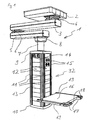
- Fig. 1 shows an isometric view of a medical supply unit 1.
- the medical supply unit 1 has a ceiling mount, which is covered by a ceiling panel 2.
- An upper tripod arm 3 is longitudinally connected at one end to the top via an upper pivot 4 with the ceiling mount.
- the middle pivot 6 is arranged in the longitudinal direction of the lower stand arm 5 at one end.
- a lower pivot 8 is arranged on the underside thereof, which in turn is connected to a spacer column 7.
- an upper end cover 9 is attached.
- the upper end cover 9, a lower end cover 10 and intervening elements form a support 32.
- the carrier 32 is cuboid shaped in this embodiment and has four long edges 11 and four intermediate longitudinal surfaces 12. In alternative embodiments, carriers with three, five or more long edges and long surfaces are possible. The basic shape is then not cuboid, but cylindrical with a suitable cross-section. Also, in other embodiments, medical care units may be provided with multiple carriers.
- a part of the long surfaces 12 is formed by built-in modules 13.
- the mounting modules 13 are arranged one above the other so that they form a continuous surface almost gap-free, which extends from the upper end cover 9 to the lower end cover 10.
- the built-in modules 13 are provided on the four sides of the carrier 32.
- the built-in modules 13 are designed as pure cover modules without internals, or as an electrical installation module 14 with built-in electrical sockets for powering medical devices, or as gas built-in modules 15 with gas taps or manometers, which serve to supply the medical apparatus with medical gases.
- a platform 16 is mounted for mounting or attaching medical apparatus or instruments.
- the platform 16 is equipped with operating handles 17, in which controls 18 are provided.
- the controls 18 are used to control actuators of the medical care unit, eg. B. controllable brakes in the hinges 4, 6 and 8.
- Laterally of the platform 16 extending rails 19.
- the rails 19 are used to hold other medical equipment or accessories.
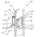
- Fig. 2 For example, one of the longitudinal surfaces 12 of the medical care unit carrier 32 is shown in an isometric view, with a mounting module 13 shown in a disassembled condition.
- the carrier 32 has an opening 20 in its longitudinal surface 12.
- resilient fastening elements 21 are provided, which are connectable to the carrier 32.
- two resilient fastening elements 21 are provided for each installation module 13. In other embodiments, however, only one resilient fastening element 21 may be provided laterally of the built-in module 13, respectively. Additionally or alternatively, fasteners may be provided on the top or bottom of the built-in module 13.
- the resilient fastening elements 21 are provided in this embodiment as separate components.
- the profiles of the carrier 32 may be formed so that the resilient fasteners 21 are already integrated therein.
- the resilient fasteners each have two resilient portions 25, one of which is shown on the upper fastener 21 and one on the lower fastener 21 within the opening 20, respectively. In order to increase the holding force, alternatively, however, a plurality of resilient portions 25 may be provided.
- the resilient fastening element 21 has a non-resilient portion 26.
- the non-resilient portion 26 serves as a vertical guide for the assembly of the mounting modules 13. It can also be provided a plurality of non-resilient portions 26.
- the resilient fastener 21 is made in this embodiment of spring steel, but it can also be used any other suitable materials.
- the installation module 13 has a front surface 23 which, when installed, forms a part of the longitudinal surface 12 together with the front surfaces 23 of the further installation modules 13.
- a cantilevered element 33 is provided on the opposite side of the front surface 23.
- the cantilevered elements 33 are formed on their sides 22 for attachment of the mounting modules 13 as described below.
- the front surface 23 is laterally formed in each case with a recessed shoulder, in which two openings 24 are provided on both sides.
- the openings 24 are suitable for allowing a special tool for releasing the built-in modules 13 to penetrate in the installed state to the resilient fastening elements 21. In other embodiments, only one breakthrough or multiple breakthroughs are possible.
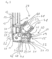
- FIG Fig. 3 A horizontal section through a portion of the carrier 32 is shown in FIG Fig. 3 shown.
- an interior space 27 is formed.
- the profile 28 has three hollow rails 39, each provided with insulating rails 40 with conductor rails 41.
- each additional mounting rails 42 are introduced.
- the hollow rails 39 are covered by the covering devices 31, in order to prevent the penetration of liquids into the hollow rails 39.
- the conductor rails 41 in the outwardly directed hollow rails 39 serve for the transmission of control signals for the operation of the medical supply unit 1, and possibly for the control of medical apparatus provided thereon.
- the Conductor rails, which are directed in the direction of the interior space 27, serve firstly for data transmission for operation of the medical supply unit, and secondly for the supply of electrical sockets or other electrical devices of the medical supply unit 1.
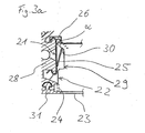
- Fig. 3a shows in detail how the profile 28 in each case in two areas, which face the built-in modules 13, has a configuration with two opposite ribs, which are suitable for the resilient fastening element 21 can be snapped.
- a positive connection and in the vertical direction generates a frictional connection, whereby the resilient fastening element 21 can be mounted at any height.
- the profile 28 can also be designed so that there is likewise a positive fit in the vertical direction.
- the installation module 13 has, as in Fig. 3 and Fig. 3a viewed from above, a certain contour.
- the sides 22 of the built-in module 13 are designed so that along their extension in the direction of the interior 27 in a region a recess 29 is arranged.
- the recess 29 has a locking surface 30 on the side which is farther from the front surface 23.
- the locking surface 30 is designed to include with the side 22 an angle ⁇ which is smaller than 90 °.
- an opening may be provided instead of the recess 29, which also has a locking surface 30 as described above.
- the non-resilient portion 26 of the resilient fastening element 21 protrudes, starting from the profile 28, in the direction of the opening 20, which is closed by the installation module 13. At a built-in module 13, the non-resilient portion 26 overlaps with the contour of the built-in module 13.
- the resilient portion 25 of the resilient fastener 21 When installing the mounting elements 13 of the resilient portion 25 of the resilient fastener 21 is pushed back by the contour of the mounting member 13, and upon further insertion of the mounting member 13 of the resilient fastener 21 of the resilient portion 25 enters into a positive engagement with the mounting member 13, since the resilient portion 25 during spring back during the installation process of the built-in module 13 engages with its end face in the recess 29 on the locking side 30 and the built-in module 13 is locked.
- the length of the resilient portion 25 is designed so that the point of contact between the resilient portion 25 and the locking surface 30 is approximately in the middle of the locking surface 30.
- the angle ⁇ and the distance of the locking surface 30 from the front surface 23 is selected so that even with maximum or minimum values in the tolerance chain, the resilient portion 25 is always in engagement with the locking surface 30.
- the apertures 24 are arranged so that after a removal or pushing away the cover 31, an access for a special tool is made possible, with which the resilient portion 25 can be pressed in the direction of the profile 28. It will the engagement between the resilient portion 25 and the locking side 30 is released and the installation module 13 is unlocked and can be pulled out of the carrier 32.
- the tool is designed so that it pushes back the resilient portion 25 when pressed in the direction of the inner space 27, and automatically pulls the built-in module 13 from the opening 20 upon retraction of the tool. Only the pushing back of the resilient portion 25 without the automatic extraction can also be done using a conventional tool, such as a screwdriver or a pen.
- the apertures 24 are covered by the cover devices 31 in order to improve the hygienic conditions.
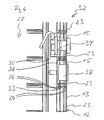
- FIG. 4 a vertical section through a portion of the carrier 32 is shown.
- the front surfaces 23 of the individual installation modules 13 are shown, which form part of the longitudinal surface 12.
- the built-in modules 13 have at the upper ends of the lateral contour of the front surface 23, starting from each a right-angled recessed heel.
- the lateral contour of the built-in modules 13 is provided in each case with a projection downwards, which is complementary to the paragraphs formed on the top thereof.
- This configuration results in a meshing of the shoulders and the projections, which avoids that liquids that run down along the front surface 23 can penetrate into the carrier 32.
- the overlapping lower portion of the front surface over the shoulder at the upper end of the front surface 23, the formation of an inwardly continuous gap between the mounting modules 13 is prevented, so that even with the occurrence of tolerances, the penetration of the liquids is prevented.
- the cheeks which form the cantilevered elements 33 on the front side 23 opposite side, are provided with a plurality of grooves 34 having different widths.
- the grooves 34 of the upper cheek 33 and the grooves 34 of the lower cheek 33 are respectively disposed opposite to each other. In alternative embodiments, the number of grooves 34 may vary and the widths of the grooves 34 may be different.
- the cheeks 33 with the grooves 34 serve as attachment means for attachments on the front surface 23 opposite side.
- each gas sockets 37 or 38 gauge are installed.
- the gas sockets 37 or pressure gauge 38 are attached to the gas installation module 15 by means of attachment parts in the form of fastening profiles 35, 36.
- the fastening profile 35, 36 has a substantially U-shaped contour, with the closed leg of the horizontal U pointing in the direction of the interior 27 of the carrier 32. At the two ends of the U-shaped contour lying opposite the closed region, the ends of the legs are bent by 180 °. They thus form engagement elements on the outside of the fastening profiles 35, 36.
- the dimensions of the fastening profile 35 are dependent on the type and mounting options of the gas sockets and pressure gauges.
- the fastening profiles can vary in depth, width, and contour.
- the mounting profile can be either in the orientation as in Fig. 4 be shown installed, or rotated through 180 °, so that the closed area of the profile in Fig. 4 located on the right side.
- the fastening profile is reduced to a mounting plate.
- the engaging elements formed on the fastening profiles 35, 36 and the mounting plate are respectively in the grooves 34, which serve as fastening means are provided at different distances from the front surface 23, inserted.
- the gas outlets and pressure gauges are connected to the central gas supply system via hoses or pipes (not shown).
- the electrical sockets are connected to the in Fig. 3 shown conductor rails 41 connected or alternatively wired directly to the power grid.
- the dimension of the built-in modules 13 in the vertical direction ie their height, is selected so that, starting from this, the further height dimensions each amount to an integer multiple thereof.
- individual modules can be easily replaced or a plurality of modules can be replaced by a module with a larger dimension, the front surface 23 is not interrupted.
- the resilient fasteners 21 are clipped by means of a device to the profile 28, that the resilient fasteners 21 a distance from each other and also from the upper end cover 9 and the lower end cover 10, so that the built-in modules 13 clipped according to their height dimensions can be.
- any small gaps that may arise due to tolerances are distributed over the entire front surface 23, so that not at one end of the front surface 23, a larger gap.
Landscapes
- Health & Medical Sciences (AREA)
- Nursing (AREA)
- Life Sciences & Earth Sciences (AREA)
- Animal Behavior & Ethology (AREA)
- General Health & Medical Sciences (AREA)
- Public Health (AREA)
- Veterinary Medicine (AREA)
- Engineering & Computer Science (AREA)
- Architecture (AREA)
- Civil Engineering (AREA)
- Structural Engineering (AREA)
- Accommodation For Nursing Or Treatment Tables (AREA)
- Infusion, Injection, And Reservoir Apparatuses (AREA)
Priority Applications (5)
| Application Number | Priority Date | Filing Date | Title |
|---|---|---|---|
| EP09159613.0A EP2248504B1 (de) | 2009-05-07 | 2009-05-07 | Medizinische Versorgungseinheit mit Einbaumodulen |
| PL09159613T PL2248504T3 (pl) | 2009-05-07 | 2009-05-07 | Medyczna jednostka zasilająca z wbudowywanymi modułami |
| US12/775,672 US8376302B2 (en) | 2009-05-07 | 2010-05-07 | Attaching modules to a medical supply unit |
| CN201010214396.1A CN101889899B (zh) | 2009-05-07 | 2010-05-07 | 具有内置式模块的医疗供给单元 |
| HK11104007.0A HK1146528B (en) | 2009-05-07 | 2011-04-20 | Medical supply unit with built-in modules |
Applications Claiming Priority (1)
| Application Number | Priority Date | Filing Date | Title |
|---|---|---|---|
| EP09159613.0A EP2248504B1 (de) | 2009-05-07 | 2009-05-07 | Medizinische Versorgungseinheit mit Einbaumodulen |
Publications (2)
| Publication Number | Publication Date |
|---|---|
| EP2248504A1 EP2248504A1 (de) | 2010-11-10 |
| EP2248504B1 true EP2248504B1 (de) | 2013-11-06 |
Family
ID=41119560
Family Applications (1)
| Application Number | Title | Priority Date | Filing Date |
|---|---|---|---|
| EP09159613.0A Active EP2248504B1 (de) | 2009-05-07 | 2009-05-07 | Medizinische Versorgungseinheit mit Einbaumodulen |
Country Status (4)
| Country | Link |
|---|---|
| US (1) | US8376302B2 (pl) |
| EP (1) | EP2248504B1 (pl) |
| CN (1) | CN101889899B (pl) |
| PL (1) | PL2248504T3 (pl) |
Families Citing this family (6)
| Publication number | Priority date | Publication date | Assignee | Title |
|---|---|---|---|---|
| AU2012364415A1 (en) * | 2012-01-04 | 2014-03-13 | Fresenius Vial Sas | Arrangement of a rack and a medical device |
| US9107792B2 (en) | 2012-09-07 | 2015-08-18 | Allen Medical Systems, Inc. | Carriage for a surgical boot of a hip distractor |
| US9730851B2 (en) | 2012-09-07 | 2017-08-15 | Allen Medical Systems, Inc. | Surgical support system |
| US8986039B2 (en) | 2013-02-19 | 2015-03-24 | Phoenix Contact Development and Manufacturing, Inc. | Shelf lighting connector assembly |
| CN103908350B (zh) | 2014-04-30 | 2016-08-17 | 迈柯唯医疗设备(苏州)有限公司 | 医用吊塔箱体 |
| CN103919615B (zh) * | 2014-04-30 | 2017-01-25 | 迈柯唯医疗设备(苏州)有限公司 | 医用吊塔箱体及用于该医用吊塔箱体的立柱 |
Family Cites Families (23)
| Publication number | Priority date | Publication date | Assignee | Title |
|---|---|---|---|---|
| US4048768A (en) * | 1976-09-30 | 1977-09-20 | Harter Corporation | Device for lockably securing appurtenances to a decorative wall |
| DE3714196C2 (de) * | 1987-04-29 | 1996-04-04 | Trilux Lenze Gmbh & Co Kg | Versorgungsbalken für die Intensivpflege |
| US5023396A (en) * | 1989-03-10 | 1991-06-11 | Square D Company | Pop-up service fitting |
| DE59004859D1 (de) * | 1989-05-24 | 1994-04-14 | Zumtobel Licht | Einbaudose für die Anbringung von Einbaugeräten, vorzugsweise von elektrischen Einbaugeräten. |
| US5165640A (en) * | 1991-10-04 | 1992-11-24 | Williams 3Rd James W | Spring clip for perforated board tool holders |
| DE4239625C1 (en) | 1992-11-26 | 1993-08-05 | Fresenius Ag, 6380 Bad Homburg, De | Medical transfusion equipment connecting column - forms connection with data exchange equipment and has two conductors secured by clamp with jaws and electrical contacts |
| US5348485A (en) * | 1993-04-12 | 1994-09-20 | Electronic Retailing Systems Int'l Inc. | Electronic price display system with vertical rail |
| DE29505072U1 (de) | 1995-03-25 | 1996-08-01 | Trilux-Lenze Gmbh + Co Kg, 59759 Arnsberg | Versorgungseinheit für eine medizinische Pflegestation |
| DE29617895U1 (de) * | 1996-10-15 | 1997-01-02 | Trilux-Lenze Gmbh + Co Kg, 59759 Arnsberg | Versorgungsbalken für die Intensivpflege |
| DE19715156C1 (de) | 1997-04-11 | 1998-08-20 | Bankamp Leuchten Gmbh | Stromschiene und Adapter für Stromschienen |
| US5907126A (en) * | 1997-09-04 | 1999-05-25 | The Wiremold Company | Metal electrical outlet box with push-in screws for mounting electrical device |
| US6196649B1 (en) * | 1998-01-15 | 2001-03-06 | Steris Corporation | Convertible surgical equipment and appliance support system |
| US5975318A (en) * | 1998-02-13 | 1999-11-02 | Display Technologies, Inc. | Display shelf assembly and bracket useful therein |
| US6070841A (en) * | 1998-03-13 | 2000-06-06 | Advertising Display Company | Universal sidekick mount bracket |
| US6230910B1 (en) * | 1998-03-31 | 2001-05-15 | Auto-Lok, Inc. | Self-locking beam clip |
| JP2002521628A (ja) * | 1998-07-22 | 2002-07-16 | ヴァンプラー アクチエンゲゼルシャフト | 圧縮空気ラインのそばにずらして配置されるユーザに給気するデバイス |
| US6056561A (en) * | 1999-02-08 | 2000-05-02 | Lin; Shan Chaing | Adapter and track arrangement for lighting fixtures |
| DE10057556A1 (de) * | 2000-11-21 | 2002-05-23 | Kreuzer Gmbh & Co Ohg | Stativkopf, insbesondere für eine medizinische Überwachungs- und Versorgungseinrichtung, Trägerprofil für einen solchen und Gerätewagen |
| US7410379B1 (en) * | 2005-04-27 | 2008-08-12 | Byrne Norman R | Multiple circuit receptacles |
| US8017865B1 (en) * | 2005-06-06 | 2011-09-13 | Taymac Corporation | Collapsible while-in-use electrical outlet cover assembly |
| CA2556124C (en) * | 2006-08-15 | 2014-04-22 | Inscape Corporation | Stacked cabinet structure with intermediate raceway |
| DE102007053327A1 (de) * | 2007-11-08 | 2009-05-14 | Trumpf Medizin Systeme Gmbh + Co.Kg | Medizinische Versorgungseinheit zur Stromversorgung und Datenübertragung bei medizinischen Apparaten |
| US8123185B2 (en) * | 2008-03-24 | 2012-02-28 | Ss3 Storage Systems, L.L.C. | Bracket release mechanism |
-
2009
- 2009-05-07 PL PL09159613T patent/PL2248504T3/pl unknown
- 2009-05-07 EP EP09159613.0A patent/EP2248504B1/de active Active
-
2010
- 2010-05-07 US US12/775,672 patent/US8376302B2/en not_active Expired - Fee Related
- 2010-05-07 CN CN201010214396.1A patent/CN101889899B/zh active Active
Also Published As
| Publication number | Publication date |
|---|---|
| CN101889899B (zh) | 2014-07-23 |
| PL2248504T3 (pl) | 2014-05-30 |
| US8376302B2 (en) | 2013-02-19 |
| HK1146528A1 (en) | 2011-06-17 |
| CN101889899A (zh) | 2010-11-24 |
| EP2248504A1 (de) | 2010-11-10 |
| US20100284731A1 (en) | 2010-11-11 |
Similar Documents
| Publication | Publication Date | Title |
|---|---|---|
| EP2248503B1 (de) | Medizinische Versorgungseinheit mit verriegelbaren Adaptern | |
| EP2058911B1 (de) | Medizinische Versorgungseinheit zur Stromversorgung und Datenübertragung bei medizinischen Apparaten | |
| EP2248504B1 (de) | Medizinische Versorgungseinheit mit Einbaumodulen | |
| DE69402525T2 (de) | Gerüst mit variabler grösse für elektrische und/oder elektronische anlage | |
| EP1336065B1 (de) | Stativkopf, insbesondere für eine medizinische überwachungs- und versorgungseinrichtung, trägerprofil für einen solchen und gerätewagen | |
| DE202015101776U1 (de) | Rangierwabe | |
| EP3607624B1 (de) | Anordnung aus einem schaltschranksockel und einem darauf montierten schaltschrankrahmengestell sowie eine entsprechende schaltschrankreihe | |
| EP3281253B1 (de) | Rangierwabe | |
| DE102006015317B4 (de) | Geräteeinbausatz zur Anordnung eines Gerätes in einer elektrischen Schaltanlage | |
| EP2523281B1 (de) | Kabelkanal | |
| EP1443617B1 (de) | Tragschienenanordnung für Schaltschränke | |
| EP2645501B1 (de) | Systemmodul für die Gebäude-Elektroinstallationstechnik und Türkommunikationstechnik | |
| DE19908350A1 (de) | Vorrichtung zum Befestigen bzw. Verdrahten von elektrischen und/oder elektronischen Bauteilen | |
| EP3419128A1 (de) | Steckdosenleiste für einen verteilerkasten | |
| DE2846948C2 (de) | Flächenkabelrost | |
| DE102019134828A1 (de) | Befestigungssystem und Schaltschrank | |
| DE10135662A1 (de) | Gerätebecherrahmen für Unterfluranwendungen | |
| DE102024132715B3 (de) | Anordnung zur montage eines elektrischen geräts an einem sammelschienensystem mit höhenverstellbarem montageelement | |
| DE4013985A1 (de) | Einschub mit montageplatte | |
| EP3931924B1 (de) | Schaltschrankanordnung mit einem schaltschrank und mindestens einer steckdosenleiste | |
| DE102009052997A1 (de) | Vorrichtung zum Anschluss elektrischer Installationsgeräte | |
| DE29713237U1 (de) | Vorrichtung zur Installation von rechteckigen mehrpoligen Verbindern für Industriezwecke auf Halteprofilen | |
| EP2653066A1 (de) | Stützbein für Arbeitsmöbel | |
| WO2012089191A1 (de) | Verbindungselement zur erstellung von medienzellen | |
| DE202010001480U1 (de) | Schutzvorrichtung für eine Steuereinrichtung sowie damit ausgestattete Steuereinheit |
Legal Events
| Date | Code | Title | Description |
|---|---|---|---|
| PUAI | Public reference made under article 153(3) epc to a published international application that has entered the european phase |
Free format text: ORIGINAL CODE: 0009012 |
|
| AK | Designated contracting states |
Kind code of ref document: A1 Designated state(s): AT BE BG CH CY CZ DE DK EE ES FI FR GB GR HR HU IE IS IT LI LT LU LV MC MK MT NL NO PL PT RO SE SI SK TR |
|
| 17P | Request for examination filed |
Effective date: 20110415 |
|
| RAP1 | Party data changed (applicant data changed or rights of an application transferred) |
Owner name: TRUMPF MEDIZIN SYSTEME GMBH + CO. KG |
|
| 17Q | First examination report despatched |
Effective date: 20120104 |
|
| GRAP | Despatch of communication of intention to grant a patent |
Free format text: ORIGINAL CODE: EPIDOSNIGR1 |
|
| INTG | Intention to grant announced |
Effective date: 20130523 |
|
| GRAS | Grant fee paid |
Free format text: ORIGINAL CODE: EPIDOSNIGR3 |
|
| GRAA | (expected) grant |
Free format text: ORIGINAL CODE: 0009210 |
|
| RIN1 | Information on inventor provided before grant (corrected) |
Inventor name: BRUNNER, JUERGEN Inventor name: HOLZ, EBERHARD Inventor name: WEISHEIT, THOMAS Inventor name: BAUER, GEORG |
|
| AK | Designated contracting states |
Kind code of ref document: B1 Designated state(s): AT BE BG CH CY CZ DE DK EE ES FI FR GB GR HR HU IE IS IT LI LT LU LV MC MK MT NL NO PL PT RO SE SI SK TR |
|
| REG | Reference to a national code |
Ref country code: GB Ref legal event code: FG4D Free format text: NOT ENGLISH |
|
| REG | Reference to a national code |
Ref country code: CH Ref legal event code: EP |
|
| REG | Reference to a national code |
Ref country code: SE Ref legal event code: TRGR |
|
| REG | Reference to a national code |
Ref country code: AT Ref legal event code: REF Ref document number: 638913 Country of ref document: AT Kind code of ref document: T Effective date: 20131215 |
|
| REG | Reference to a national code |
Ref country code: IE Ref legal event code: FG4D Free format text: LANGUAGE OF EP DOCUMENT: GERMAN |
|
| REG | Reference to a national code |
Ref country code: DE Ref legal event code: R096 Ref document number: 502009008278 Country of ref document: DE Effective date: 20140102 |
|
| REG | Reference to a national code |
Ref country code: NL Ref legal event code: VDEP Effective date: 20131106 |
|
| REG | Reference to a national code |
Ref country code: LT Ref legal event code: MG4D |
|
| PG25 | Lapsed in a contracting state [announced via postgrant information from national office to epo] |
Ref country code: NL Free format text: LAPSE BECAUSE OF FAILURE TO SUBMIT A TRANSLATION OF THE DESCRIPTION OR TO PAY THE FEE WITHIN THE PRESCRIBED TIME-LIMIT Effective date: 20131106 Ref country code: NO Free format text: LAPSE BECAUSE OF FAILURE TO SUBMIT A TRANSLATION OF THE DESCRIPTION OR TO PAY THE FEE WITHIN THE PRESCRIBED TIME-LIMIT Effective date: 20140206 Ref country code: FI Free format text: LAPSE BECAUSE OF FAILURE TO SUBMIT A TRANSLATION OF THE DESCRIPTION OR TO PAY THE FEE WITHIN THE PRESCRIBED TIME-LIMIT Effective date: 20131106 Ref country code: LT Free format text: LAPSE BECAUSE OF FAILURE TO SUBMIT A TRANSLATION OF THE DESCRIPTION OR TO PAY THE FEE WITHIN THE PRESCRIBED TIME-LIMIT Effective date: 20131106 Ref country code: IS Free format text: LAPSE BECAUSE OF FAILURE TO SUBMIT A TRANSLATION OF THE DESCRIPTION OR TO PAY THE FEE WITHIN THE PRESCRIBED TIME-LIMIT Effective date: 20140306 Ref country code: HR Free format text: LAPSE BECAUSE OF FAILURE TO SUBMIT A TRANSLATION OF THE DESCRIPTION OR TO PAY THE FEE WITHIN THE PRESCRIBED TIME-LIMIT Effective date: 20131106 |
|
| PG25 | Lapsed in a contracting state [announced via postgrant information from national office to epo] |
Ref country code: ES Free format text: LAPSE BECAUSE OF FAILURE TO SUBMIT A TRANSLATION OF THE DESCRIPTION OR TO PAY THE FEE WITHIN THE PRESCRIBED TIME-LIMIT Effective date: 20131106 Ref country code: LV Free format text: LAPSE BECAUSE OF FAILURE TO SUBMIT A TRANSLATION OF THE DESCRIPTION OR TO PAY THE FEE WITHIN THE PRESCRIBED TIME-LIMIT Effective date: 20131106 |
|
| REG | Reference to a national code |
Ref country code: PL Ref legal event code: T3 |
|
| PG25 | Lapsed in a contracting state [announced via postgrant information from national office to epo] |
Ref country code: PT Free format text: LAPSE BECAUSE OF FAILURE TO SUBMIT A TRANSLATION OF THE DESCRIPTION OR TO PAY THE FEE WITHIN THE PRESCRIBED TIME-LIMIT Effective date: 20140306 |
|
| PG25 | Lapsed in a contracting state [announced via postgrant information from national office to epo] |
Ref country code: EE Free format text: LAPSE BECAUSE OF FAILURE TO SUBMIT A TRANSLATION OF THE DESCRIPTION OR TO PAY THE FEE WITHIN THE PRESCRIBED TIME-LIMIT Effective date: 20131106 |
|
| REG | Reference to a national code |
Ref country code: DE Ref legal event code: R097 Ref document number: 502009008278 Country of ref document: DE |
|
| PG25 | Lapsed in a contracting state [announced via postgrant information from national office to epo] |
Ref country code: RO Free format text: LAPSE BECAUSE OF FAILURE TO SUBMIT A TRANSLATION OF THE DESCRIPTION OR TO PAY THE FEE WITHIN THE PRESCRIBED TIME-LIMIT Effective date: 20131106 Ref country code: SK Free format text: LAPSE BECAUSE OF FAILURE TO SUBMIT A TRANSLATION OF THE DESCRIPTION OR TO PAY THE FEE WITHIN THE PRESCRIBED TIME-LIMIT Effective date: 20131106 |
|
| PLBE | No opposition filed within time limit |
Free format text: ORIGINAL CODE: 0009261 |
|
| STAA | Information on the status of an ep patent application or granted ep patent |
Free format text: STATUS: NO OPPOSITION FILED WITHIN TIME LIMIT |
|
| PG25 | Lapsed in a contracting state [announced via postgrant information from national office to epo] |
Ref country code: DK Free format text: LAPSE BECAUSE OF FAILURE TO SUBMIT A TRANSLATION OF THE DESCRIPTION OR TO PAY THE FEE WITHIN THE PRESCRIBED TIME-LIMIT Effective date: 20131106 |
|
| 26N | No opposition filed |
Effective date: 20140807 |
|
| REG | Reference to a national code |
Ref country code: DE Ref legal event code: R097 Ref document number: 502009008278 Country of ref document: DE Effective date: 20140807 |
|
| PG25 | Lapsed in a contracting state [announced via postgrant information from national office to epo] |
Ref country code: LU Free format text: LAPSE BECAUSE OF FAILURE TO SUBMIT A TRANSLATION OF THE DESCRIPTION OR TO PAY THE FEE WITHIN THE PRESCRIBED TIME-LIMIT Effective date: 20140507 |
|
| REG | Reference to a national code |
Ref country code: CH Ref legal event code: PL |
|
| GBPC | Gb: european patent ceased through non-payment of renewal fee |
Effective date: 20140507 |
|
| PG25 | Lapsed in a contracting state [announced via postgrant information from national office to epo] |
Ref country code: LI Free format text: LAPSE BECAUSE OF NON-PAYMENT OF DUE FEES Effective date: 20140531 Ref country code: MC Free format text: LAPSE BECAUSE OF FAILURE TO SUBMIT A TRANSLATION OF THE DESCRIPTION OR TO PAY THE FEE WITHIN THE PRESCRIBED TIME-LIMIT Effective date: 20131106 Ref country code: CH Free format text: LAPSE BECAUSE OF NON-PAYMENT OF DUE FEES Effective date: 20140531 |
|
| REG | Reference to a national code |
Ref country code: IE Ref legal event code: MM4A |
|
| PG25 | Lapsed in a contracting state [announced via postgrant information from national office to epo] |
Ref country code: SI Free format text: LAPSE BECAUSE OF FAILURE TO SUBMIT A TRANSLATION OF THE DESCRIPTION OR TO PAY THE FEE WITHIN THE PRESCRIBED TIME-LIMIT Effective date: 20131106 |
|
| PG25 | Lapsed in a contracting state [announced via postgrant information from national office to epo] |
Ref country code: IE Free format text: LAPSE BECAUSE OF NON-PAYMENT OF DUE FEES Effective date: 20140507 |
|
| PG25 | Lapsed in a contracting state [announced via postgrant information from national office to epo] |
Ref country code: GB Free format text: LAPSE BECAUSE OF NON-PAYMENT OF DUE FEES Effective date: 20140507 |
|
| REG | Reference to a national code |
Ref country code: AT Ref legal event code: MM01 Ref document number: 638913 Country of ref document: AT Kind code of ref document: T Effective date: 20140507 |
|
| PG25 | Lapsed in a contracting state [announced via postgrant information from national office to epo] |
Ref country code: AT Free format text: LAPSE BECAUSE OF NON-PAYMENT OF DUE FEES Effective date: 20140507 |
|
| PG25 | Lapsed in a contracting state [announced via postgrant information from national office to epo] |
Ref country code: MT Free format text: LAPSE BECAUSE OF FAILURE TO SUBMIT A TRANSLATION OF THE DESCRIPTION OR TO PAY THE FEE WITHIN THE PRESCRIBED TIME-LIMIT Effective date: 20131106 |
|
| REG | Reference to a national code |
Ref country code: FR Ref legal event code: PLFP Year of fee payment: 8 |
|
| PGFP | Annual fee paid to national office [announced via postgrant information from national office to epo] |
Ref country code: PL Payment date: 20160314 Year of fee payment: 8 |
|
| PG25 | Lapsed in a contracting state [announced via postgrant information from national office to epo] |
Ref country code: CY Free format text: LAPSE BECAUSE OF FAILURE TO SUBMIT A TRANSLATION OF THE DESCRIPTION OR TO PAY THE FEE WITHIN THE PRESCRIBED TIME-LIMIT Effective date: 20131106 Ref country code: GR Free format text: LAPSE BECAUSE OF FAILURE TO SUBMIT A TRANSLATION OF THE DESCRIPTION OR TO PAY THE FEE WITHIN THE PRESCRIBED TIME-LIMIT Effective date: 20140207 Ref country code: BG Free format text: LAPSE BECAUSE OF FAILURE TO SUBMIT A TRANSLATION OF THE DESCRIPTION OR TO PAY THE FEE WITHIN THE PRESCRIBED TIME-LIMIT Effective date: 20131106 |
|
| PG25 | Lapsed in a contracting state [announced via postgrant information from national office to epo] |
Ref country code: BE Free format text: LAPSE BECAUSE OF FAILURE TO SUBMIT A TRANSLATION OF THE DESCRIPTION OR TO PAY THE FEE WITHIN THE PRESCRIBED TIME-LIMIT Effective date: 20140531 Ref country code: HU Free format text: LAPSE BECAUSE OF FAILURE TO SUBMIT A TRANSLATION OF THE DESCRIPTION OR TO PAY THE FEE WITHIN THE PRESCRIBED TIME-LIMIT; INVALID AB INITIO Effective date: 20090507 |
|
| PGFP | Annual fee paid to national office [announced via postgrant information from national office to epo] |
Ref country code: CZ Payment date: 20160412 Year of fee payment: 8 |
|
| PGFP | Annual fee paid to national office [announced via postgrant information from national office to epo] |
Ref country code: SE Payment date: 20160511 Year of fee payment: 8 Ref country code: IT Payment date: 20160524 Year of fee payment: 8 Ref country code: FR Payment date: 20160412 Year of fee payment: 8 |
|
| REG | Reference to a national code |
Ref country code: SE Ref legal event code: EUG |
|
| PG25 | Lapsed in a contracting state [announced via postgrant information from national office to epo] |
Ref country code: CZ Free format text: LAPSE BECAUSE OF NON-PAYMENT OF DUE FEES Effective date: 20170507 |
|
| PG25 | Lapsed in a contracting state [announced via postgrant information from national office to epo] |
Ref country code: SE Free format text: LAPSE BECAUSE OF NON-PAYMENT OF DUE FEES Effective date: 20170508 |
|
| REG | Reference to a national code |
Ref country code: FR Ref legal event code: ST Effective date: 20180131 |
|
| PG25 | Lapsed in a contracting state [announced via postgrant information from national office to epo] |
Ref country code: IT Free format text: LAPSE BECAUSE OF NON-PAYMENT OF DUE FEES Effective date: 20170507 Ref country code: FR Free format text: LAPSE BECAUSE OF NON-PAYMENT OF DUE FEES Effective date: 20170531 |
|
| PG25 | Lapsed in a contracting state [announced via postgrant information from national office to epo] |
Ref country code: MK Free format text: LAPSE BECAUSE OF FAILURE TO SUBMIT A TRANSLATION OF THE DESCRIPTION OR TO PAY THE FEE WITHIN THE PRESCRIBED TIME-LIMIT Effective date: 20131106 |
|
| PG25 | Lapsed in a contracting state [announced via postgrant information from national office to epo] |
Ref country code: PL Free format text: LAPSE BECAUSE OF NON-PAYMENT OF DUE FEES Effective date: 20170507 |
|
| PGFP | Annual fee paid to national office [announced via postgrant information from national office to epo] |
Ref country code: TR Payment date: 20220421 Year of fee payment: 14 |
|
| PGFP | Annual fee paid to national office [announced via postgrant information from national office to epo] |
Ref country code: DE Payment date: 20250423 Year of fee payment: 17 |