EP2248227B1 - Linsensteckverbinder - Google Patents
Linsensteckverbinder Download PDFInfo
- Publication number
- EP2248227B1 EP2248227B1 EP09709401.5A EP09709401A EP2248227B1 EP 2248227 B1 EP2248227 B1 EP 2248227B1 EP 09709401 A EP09709401 A EP 09709401A EP 2248227 B1 EP2248227 B1 EP 2248227B1
- Authority
- EP
- European Patent Office
- Prior art keywords
- array
- flexible beams
- flexible
- connector
- beams
- Prior art date
- Legal status (The legal status is an assumption and is not a legal conclusion. Google has not performed a legal analysis and makes no representation as to the accuracy of the status listed.)
- Active
Links
- 230000013011 mating Effects 0.000 claims description 75
- 238000003491 array Methods 0.000 claims description 44
- 238000000034 method Methods 0.000 claims description 33
- 239000000463 material Substances 0.000 claims description 26
- 238000005452 bending Methods 0.000 claims description 14
- 239000004020 conductor Substances 0.000 claims description 10
- 230000000694 effects Effects 0.000 claims description 2
- 238000003780 insertion Methods 0.000 description 31
- 230000037431 insertion Effects 0.000 description 31
- 230000008569 process Effects 0.000 description 14
- 230000033001 locomotion Effects 0.000 description 11
- 238000013459 approach Methods 0.000 description 8
- 238000004519 manufacturing process Methods 0.000 description 7
- 230000036316 preload Effects 0.000 description 6
- DMFGNRRURHSENX-UHFFFAOYSA-N beryllium copper Chemical compound [Be].[Cu] DMFGNRRURHSENX-UHFFFAOYSA-N 0.000 description 4
- 230000004048 modification Effects 0.000 description 3
- 238000012986 modification Methods 0.000 description 3
- 230000004075 alteration Effects 0.000 description 2
- 230000006872 improvement Effects 0.000 description 2
- 229910052751 metal Inorganic materials 0.000 description 2
- 239000002184 metal Substances 0.000 description 2
- 230000037361 pathway Effects 0.000 description 2
- 230000009467 reduction Effects 0.000 description 2
- 238000003466 welding Methods 0.000 description 2
- RYGMFSIKBFXOCR-UHFFFAOYSA-N Copper Chemical compound [Cu] RYGMFSIKBFXOCR-UHFFFAOYSA-N 0.000 description 1
- 230000009471 action Effects 0.000 description 1
- 230000005540 biological transmission Effects 0.000 description 1
- 238000005219 brazing Methods 0.000 description 1
- 238000000576 coating method Methods 0.000 description 1
- 229910052802 copper Inorganic materials 0.000 description 1
- 239000010949 copper Substances 0.000 description 1
- 238000013461 design Methods 0.000 description 1
- 238000006073 displacement reaction Methods 0.000 description 1
- 239000012535 impurity Substances 0.000 description 1
- 230000003993 interaction Effects 0.000 description 1
- 230000005226 mechanical processes and functions Effects 0.000 description 1
- 230000003647 oxidation Effects 0.000 description 1
- 238000007254 oxidation reaction Methods 0.000 description 1
- 239000012858 resilient material Substances 0.000 description 1
- 229910001220 stainless steel Inorganic materials 0.000 description 1
- 239000010935 stainless steel Substances 0.000 description 1
Images


Classifications
-
- H—ELECTRICITY
- H01—ELECTRIC ELEMENTS
- H01R—ELECTRICALLY-CONDUCTIVE CONNECTIONS; STRUCTURAL ASSOCIATIONS OF A PLURALITY OF MUTUALLY-INSULATED ELECTRICAL CONNECTING ELEMENTS; COUPLING DEVICES; CURRENT COLLECTORS
- H01R13/00—Details of coupling devices of the kinds covered by groups H01R12/70 or H01R24/00 - H01R33/00
- H01R13/02—Contact members
- H01R13/15—Pins, blades or sockets having separate spring member for producing or increasing contact pressure
- H01R13/187—Pins, blades or sockets having separate spring member for producing or increasing contact pressure with spring member in the socket
-
- H—ELECTRICITY
- H01—ELECTRIC ELEMENTS
- H01R—ELECTRICALLY-CONDUCTIVE CONNECTIONS; STRUCTURAL ASSOCIATIONS OF A PLURALITY OF MUTUALLY-INSULATED ELECTRICAL CONNECTING ELEMENTS; COUPLING DEVICES; CURRENT COLLECTORS
- H01R43/00—Apparatus or processes specially adapted for manufacturing, assembling, maintaining, or repairing of line connectors or current collectors or for joining electric conductors
- H01R43/16—Apparatus or processes specially adapted for manufacturing, assembling, maintaining, or repairing of line connectors or current collectors or for joining electric conductors for manufacturing contact members, e.g. by punching and by bending
-
- Y—GENERAL TAGGING OF NEW TECHNOLOGICAL DEVELOPMENTS; GENERAL TAGGING OF CROSS-SECTIONAL TECHNOLOGIES SPANNING OVER SEVERAL SECTIONS OF THE IPC; TECHNICAL SUBJECTS COVERED BY FORMER USPC CROSS-REFERENCE ART COLLECTIONS [XRACs] AND DIGESTS
- Y10—TECHNICAL SUBJECTS COVERED BY FORMER USPC
- Y10T—TECHNICAL SUBJECTS COVERED BY FORMER US CLASSIFICATION
- Y10T29/00—Metal working
- Y10T29/49—Method of mechanical manufacture
- Y10T29/49002—Electrical device making
- Y10T29/49117—Conductor or circuit manufacturing
- Y10T29/49204—Contact or terminal manufacturing
Definitions
- the invention relates to electrical connectors.
- an electrical connector for connecting to a mating connector.
- the electrical connector comprises a first array of flexible beams that extend from a base.
- the first array of flexible beams is arranged about a substantially cylindrical cavity that is configured to receive the mating connector.
- Distal portions of each flexible beam of the first array extend inwardly toward the cavity and have a contact area with a surface that defines two or more contact points to provide an electrical connection with the mating connector, when received in the cavity.
- the two or more contact points are spaced from one another along a radius that revolves about the substantially cylindrical cavity.
- a method of forming an electrical connector comprises providing a sheet of conductive material. Portions of the sheet are lanced to separate a first array of flexible beams from a second array of flexible beams. The first and second array of flexible beams remain connected to one another through a base portion of the sheet. Distal portions of the first array of flexible beams are bent to define a first set of contact areas. Distal portions of the second array of flexible beams are bent to define a second set of contact areas. The base and first and second arrays of flexible beams are bent to define a substantially cylindrical cavity configured to receive a mating connector.
- a method of forming an electrical connector comprises providing a first and second sheet portions of conductive material.
- the first sheet portion is blanked to define a first base portion and a first array of flexible beams extending therefrom.
- the second sheet portion is blanked to define a second base portion and a second array of flexible beams extending therefrom.
- Distal portions of the first array of flexible beams are bent to define a first set of contact areas and distal portions of the second array of flexible beams are bent to define a second set of contact areas.
- the first and second arrays of flexible beams are bent to define a substantially cylindrical cavity configured to receive a mating connector.
- the second array of flexible beams is nested in the first array of flexible beams.
- An aspect of the invention described herein relates to including a first and a second array of flexible beams in a connector.
- the flexible beams provide an electrical connection to a mating connector, when received in a cavity that lies between at least some of the beams.
- a distal portion of each flexible beam includes a contact point that makes electrical contact with the mating connector.
- the first and second arrays of flexible beams may be overlapped with one another. In this respect, an overall size of the electrical connector may be reduced, while providing an increased number of contacts and/or contact area for engagement with a mating connector.
- the flexible beams may have contact areas shaped to define multiple contact points that contact a mating connector.
- the total number of contact points may be increased, and correspondingly, the current carrying capacity of the connector may also be increased.
- the connector may be manufactured through a stamping process, such that the connector may be produced cost effectively.
- the first and second arrays of flexible beams may be lanced from a common sheet of material. This may be accomplished without removing any material that lies between flexible beams of the first and second arrays, which may reduce the amount of material used to manufacture the connector, and thus reduce production costs.
- contact points of the first and second arrays of flexible beams may be separated from one another along the direction in which the mating connector is received, which may allow additional contacts to be included within the connector.
- FIG. 1 shows a cut-away view of an electrical connector, according to one embodiment.
- the connector includes a hood 10, a first array 12, and a second array 14 of flexible beams 16 that each include one or more contact points 18. Together with the hood, the flexible beams and contact points define a substantially cylindrical cavity 20 in which a mating connector 22 may be received.
- Each array of flexible beams is connected to a base 24 at one end, and at the other end has a contact area 26 with one or more contact points 18 that extend inwardly of the cylindrical cavity such that they may make an electrical connection with a mating connector, when received.
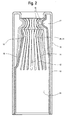
- Another illustrative embodiment, shown in FIG. 2 includes a first and second array of flexible beams that are formed from a common portion of material, and that have a common base 24.
- Embodiments of invention include various features to increase the amount of contact area with a mating connector without also necessarily increasing the size of the overall envelope occupied by the connector.
- One such feature includes the radius about which contacts of the first and second arrays lie.
- the flexible beams shown in FIGs. 1 and 2 are connected to a base that lies at a radius that is larger than that on which the contact areas lie.
- any gap 27 between each of the flexible beams at the contact areas may be smaller than the gap between the flexible beams near the base 24. This reduction in gap size at the contact areas may allow for additional beams to be included in a connector and/or for larger contact areas at each connector, either of which may increase the total area of contact with the mating connector and reduce the overall electrical resistance associated with the connector.
- the flexible beams may contact one another, thus eliminating any gaps therebetween, at least when a mating connector is not present in the cavity. It is, however, to be appreciated that not all embodiments include flexible beams configured to reduce gap size between contacts, as aspects of the invention are not limited in this respect.
- connectors may be configured such that the base and array(s) of flexible beams do not extend about a curved surface, such as in embodiments that include a slot-like cavity for receiving a mating connector.
- Arrays of flexible beams may be overlapped or nested with one another to increase the area available to make contact with a mating connector, without also necessarily increasing the overall size of the connector. Examples of such overlapped connectors are shown in the embodiments of FIGs. 1 and 2 . Configuring the beams in a nested manner, as shown, may help reduce the overall length of the connector, taken along the "insertion direction" - the direction in which the mating connector is inserted to the cavity of the connector. Overlapped configurations may allow the flexible beams to have lengths appropriate for the desired contact forces, displacement ranges, and/or other features that may be desirable for a particular connector, without also increasing the overall connector envelope. Although FIGs.
- FIG. 1 and 2 show a pair of nested flexible arrays, it is to be appreciated that a connector having a single array, or more arrays than two, are also possible. By way of example, some embodiments may have 3 arrays, 4 arrays, 5 arrays or even more than 5 nested arrays of flexible beams.
- the terms 'overlapped' or 'nested' refer to portions of a second array of flexible beams being positioned, at least partially, between the cavity and a first array of flexible beams. Individual beams do not have to be precisely aligned over gaps or beams of another array to be considered 'overlapped' or 'nested'. Neither do flexible beams of different arrays within a connector have extend the same length in the direction of insertion within a connector to be considered 'overlapped' or 'nested'.
- Overlapping arrays of flexible beams may, additionally or alternately, allow the insertion length of a connector to be reduced.
- insertion length refers to the length that a mating connector must travel, along the insertion direction, until the full electrical pathway between the electrical connector and mating connector is realized, after an initial electrical contact is made. In the embodiments of FIGs. 1 and 2 , the insertion length is the distance between the contact points 18 of the first 12 and second 14 arrays, taken along the direction of insertion.
- the flexible beams may be made of a resilient material, such as beryllium copper or other conductive material, so that flexing of the beams themselves may provide contact forces between the contact points of the connector and the mating connector.
- additional mechanical elements for providing a biasing force may be omitted from the connector altogether, which may also help maintain a high ratio contact area to connector envelope size. It is to be appreciated, however, that additional mechanical elements may be included to provide contact forces, as aspects of the invention are not limited in this respect.
- Embodiments of the connector may incorporate various features to promote a good electrical connection with the mating connector.
- a degree of wiping between contact points of the connector and the surface of a mating connector may be desirable during the connection process. This wiping action may remove undesirable oxidation, impurities, and/or debris that might exist on the contact points and/or the mating connector.
- too much wiping may remove coatings from the mating element and/or contact points or otherwise damage portions of a connector, and thus it may be desirable to limit the amount of wiping that occurs in any one area.
- the contact points associated with the first array and second array may be rotated about the cavity, relative to contacts of the second set (that is, rotated about an axis that lies parallel to the insertion direction, as represented schematically in FIG. 3 ).
- each contact point may wipe a different area of a mating connector, when inserted, to help prevent excess wiping from occurring at any one given spot.
- flexible beams of the second array may be aligned over the gaps of the first array with respect to one another, as shown in FIG. 3 and as occurs inherently in the embodiment shown in FIG. 2 . It is to be appreciated that not all embodiments may have contact points rotated about the cavity relative to one another, as aspects of the invention are not limited in this respect. Moreover, other approaches may be used, additionally or alternately, to control the amount of wiping between contact points and a mating connector.
- Surfaces 30 of the contact areas that face toward the cavity may be shaped to provide multiple contact points 18 separated from one another in a direction orthogonal to the insertion direction.
- the surface 30 may be shaped to have a concave curvature 32 as shown in FIG. 4 , to help accomplish this effect.
- the curvature, as shown, is greater than that of the mating connector 22 such that the contact area should touch the mating connector at two contact points, positioned at lateral portions of the surface that faces the cavity. Contact points of each flexible beam formed in this manner will make contact with a mating connector at substantially the same time during the insertion process.
- Providing two contact points for each flexible beam may ultimately provide a greater area for electrical connection with a mating connector that has a rounded surface, particularly since otherwise matching the curvature of a contact point to that of a mating connector may be difficult to accomplish.
- the curved surface of the contact area may be formed through various approaches, including a coining operation, or through various other techniques, as aspects of the invention are not limited in this respect.
- the surface may also include shapes other than a concave curvature, as aspects of the present invention are not limited in this respect.
- Embodiments of the invention may include features to promote proper insertion of a mating connector.
- One such feature includes the hood 34 at the opening of the connector, as shown in FIGs. 1 , 2 , and 5 .
- the hood has an aperture 36 that defines the maximum diameter of mating connector that may be inserted into the cavity.
- the aperture may prevent oversized mating connectors from inadvertently being inserted into cavity, which might otherwise damage the connector.
- the hood, or other features of the connector may engage the flexible beams to prevent stubbing.
- Stubbing occurs when a flexible beam moves across the cavity, instead of away from the cavity, upon insertion of a mating connector, and can result in an improper connection or damage.
- the hood embodiments of FIGs. 1 , 2 and 5 includes a lip 38 that engages the flexible beams of the first array to prevent inward movement beyond a particular point, and in this respect, may prevent stubbing. It is to be appreciated that other features may be incorporated into the connector to prevent stubbing.
- the flexible beams of the second array as shown in FIGs. 1 and 2 , include distal ends that are angled away from the cavity.
- the angled end help promote an outward movement of the beams upon engagement with a mating connector, which may help prevent stubbing.
- the distal ends of the flexible beams in the second array lie along a radius that is about equal to or larger than that of pins that may be received through the hood of the connector. This arrangement may prevent a mating connector from directly contacting the extreme distal end of the flexible beam, and thus may prevent stubbing.
- FIG. 5 shows, schematically, forces associated with inserting a radiused mating connector into the connector, according to one embodiment.
- the arrangement of the contact and mating connector causes an initial portion 40 of the insertion force 42 applied along the direction of insertion, to be directed outwardly, in a radial direction that is substantially perpendicular to the insertion direction of the connector.
- This outward radial force 40 may help push the flexible beams of the first array (or any other arrays) outwardly.
- the point of engagement 44 between the mating connector and the contact point may move about the radiused surface of the mating connector, such that less of the insertion force is directed radially outward and a greater proportion is directed along the direction of insertion.
- the flexible beams may be preloaded against the hood, as shown in FIG. 5 , which helps ensure that a contact force at least equal to the preload is applied to a mating connector if a corresponding flexible beam is moved at all away from the hood.
- the flexible beams, at least of the first array may be preloaded with a force of about 5 grams per contact point on the beam. That is, for beams with a single contact point, the preload may be about 5 grams, and for beams with a curved face having a contact point on either lateral side, as shown in FIG.
- the preload may be about 10 grams. It is, however, to be appreciated that preloads of greater or smaller magnitudes are also possible. Preloads may typically be expected to range between about 3 grams and about 75 grams per contact point for embodiments that are configured to mate with a 0.094" 0.238 cm diameter pin (size 12). Preloads for mating connectors of other sizes may lie within this range, or may even be greater, as aspects of the invention are not limited in this respect.
- the maximum insertion force required to insert a mating connector may also be controlled through various schemes, such as by having contact points arranged to make contact with the mating connector at different times during insertion. This is accomplished in the embodiments of FIGs. 1 and 2 by separating contacts associated with the first and second arrays of flexible beams along the direction of insertion. As is to be appreciated, initial contact between the mating connector and a contact point in the connector may be associated with a greater force, at least until the contact point is moved outwardly, through its range of motion, away from the cylindrical cavity of the connector. In the embodiments of FIGs.
- the contact points of the first array of flexible beams are moved at least partially through their range of motion prior to contact being made between the mating connector and contact points of the second array of flexible beams. Since the contact points associated with the second array are moved through their range of motion at a later time, the greater forces associated with initially moving these contact points outwardly is not present at the same time, during insertion, as the greater forces associated with moving the contact points of the first array. Consequently, the overall maximum insertion force may be reduced.
- flexible beams of the first array are configured such that the contact points are staggered, relative to one another, in the direction of insertion.
- contact points of the first array move through their range of motion at different times to further reduce the maximum insertion force for inserting a mating connector.
- arrays of flexible beams being overlapped in the connector may help reduce the insertion length of a connector.
- This aspect of the invention may prove particularly helpful in embodiments like that described above, where contact points of a common array are staggered relative to one another in the direction of insertion. It is to be appreciated, however, that embodiments may have flexible beams with corresponding contact points arranged to lie about a circle 28 (i.e., that are not staggered), like that of FIGs. 1 and 2 , as aspects of the invention are not limited in this respect.
- Illustrative embodiments of the connector allow flexible beams to be configured to provide desired contact forces and appropriate ranges of motions to accommodate mating connectors during insertion. It is to be appreciated that beam mechanics may determine, at least partially, the amount of force that is associated with moving each of the flexible beams through their range of motion, and thus the contact force that is applied to a mating connector. Overlapping flexible beams, such as those shown in FIGs. 1 and 2 , may provide space within the connector for each of the flexible beams to be configured to apply desired contact forces through a desired range of motion. Some of the variables that may be altered in the design of the beams include beam length, beam width in either the radial or circumferential direction, beam cross-sectional shape, material, and the like.
- FIGs. 1 and 2 are typically configured to provide about 5 grams to about 25 grams per contact point, against a mating connector, after the contact points move through a range of radial motion of about 0.008", 0.020 cm from an unbiased position, or about 0.005' 0.012 cm from a preloaded position. It is to be appreciated, however, that other ranges of motions and contact forces may be desirable for other embodiments, and that aspects of the invention are not limited to any one set of values.
- Embodiments of the invention may facilitate manufacture in a cost effective manner.
- One approach for manufacturing the embodiment of FIG. 1 includes stamping components of the connector from sheets of conductive material as is described in greater detail below, and is illustrated in a representative manner in FIGs. 6a - 6c .
- flat sheets of conductive material like beryllium copper, are blanked to define flexible beams extending from a base, as shown in FIG. 6a .
- Each of the flexible beams may be blanked at a common time with a single die, or portions of the flexible array may be blanked progressively, at different times, as aspects of the invention are not limited in this manner.
- the face of each flexible beam may be coined to define multiple contact points that will make contact with a mating connector.
- the flexible beams may be bent, either before or after blanking and/or coining, to define a contact area that extends into a plane other than that occupied by the base, and to shape the flexible beams as may be desired for a particular embodiment.
- FIG. 6b Examples of how flexible beams of the first array and second array are shown in FIG. 6b .
- the sheets of material are then bent, about an axis that lies substantially parallel to the flexible beams, into a cylindrical shape. During this bending process, the contact areas extend inwardly toward the cylindrical cavity such that they lie along a smaller radius than the base of the sheet, which, as described herein, may reduce gaps between the contact areas.
- the cylindrical sheets of material that includes the second array of flexible beams may then be nested in the cylindrical sheet of material that includes the first array of beams, as shown in FIG. 6c .
- the nested arrays of flexible beams may then be positioned in a hood to form a connector.
- steps for manufacturing the embodiment of FIG. 1 are merely exemplary, and that other approaches may also be taken, as aspects of the invention are not limited in this respect.
- the order of steps may be altered, steps may be omitted, and/or steps may be accomplished by alternate approaches.
- the entire manufacturing process may be automated, performed manually, or may include any combination of automated and manual operations.
- the shape of the flexible beams maybe be imparted to a sheet of material prior to the sheet being blanked to define the flexible beams.
- connectors may be formed by continuously stamping the first and second arrays of flexible beams from two separate strips of metal.
- Machines that process the separate strips of material may be configured such that the first array of flexible beams is formed adjacent to the second array of flexible beams. Once stamped, the first and second arrays may be assembled together by sliding the arrays relative to one another as a part of the continuous forming process. Similarly, the hood may be slid onto the nested arrays of flexible beams as a part of the continuous forming process. In other embodiments, each of the first and second arrays may be progressively formed from different portions of a common strip of material.
- the embodiment shown in FIG. 2 may be made through a procedure similar to that described above, except that the first and second arrays of flexible beams may be stamped from a common portion of a sheet of material such that they share a common base.
- material costs for a connector may be reduced by eliminating the need for a larger sheet of material or a second sheet of material, and by reducing wasted material, such as material that would otherwise be removed from between the flexible beams.
- a lancing process may be used to separate flexible beams of a first and second array from a common sheet of material. The flexible beams may be coined after the lancing process and shape may then be imparted to the flexible beams, either before or after the lancing process.
- the hood is formed of stainless steel and is shaped through a deep drawing process.
- the hood may perform primarily a mechanical function.
- the hood may also be stamped, like the flexible arrays of connectors, and may be made of a more conductive material, as aspects of the invention are not limited in this respect.
- the first array of nested connectors is first positioned inside of the hood, and then the second arrays then positioned inside of the first array.
- Each of the arrays of flexible beams and the hood may then be held together through a fastening process, like welding, brazing, staking, and the like.
- a fastening process like welding, brazing, staking, and the like.
- a portion of material in the base of an array or the hood is deformed until the portion of material interferes with the mating component, and thus prevents the components from separating.
- first and second arrays may first be assembled together and then held together through various fastening techniques, like welding, riveting, press fitting, and/or staking.
- the assembled first and second arrays may then be positioned in the hood. Similar fastening techniques may be used to hold the assembled arrays of flexible beams to the hood.
- Embodiments of the hood may be terminated to a mating component according to different approaches.
- a conductive plug of material such as copper
- the plug may compress the base of the sheet or sheets of material, in a press fit manner, against the hood to hold the connector in place.
- the plug may be cylindrical in shape to allow a mating connector to pass therethrough.
- the base portion of the connector may be extended if the connector is to provide mechanical support to a mating component, such as a cable. Such lengths may be reduced when less mechanical support may be involved, such as in board-to-board type connections.
- Applications that involve a hot plug may include a hood that is conductive or that incorporates conductive material that makes initial electrical contact with the mating connector, during insertion. In some embodiments, this conductive material may be positioned outside of the hood and may extend inwardly of the aperture in the hood, although other configurations are also possible.
- Embodiments of the invention may be configured to transmit power or data.
- each of the embodiments shown in FIGs. 1 and 2 are configured to transmit power.
- each of the contact points are typically provide an electrical pathway to a common point in the connector, like the base.
- the base may be terminated to a point outside of the connector to convey electrical power to a mating component.
- the high ratio of contact area to the size of the connector envelop may allow the connector to transmit electrical power with relative low losses, thus making embodiments suitable for power transmission.
- FIGs. 1 and 2 include a substantially cylindrical cavity that is to receive a round, pin-shaped mating connector. It is to be appreciated, however, that connectors may also be configured to define cavities for receiving mating connectors of other shapes. By way of example, embodiments may include arrays of flexible beams arranged to define a rectangular or square cavity for receiving a rectangular or square mating connector, a slot shaped cavity for receiving a card edge, or a metal blades of a bus bar. It is also to be appreciated that the connector described herein may be a subcomponent of a larger assembly, that in some cases, includes multiple connectors like those described herein.
- One example, constructed generally lie that shown in FIG. 1 has a first array of 23 flexible beams stamped from a 0.007", 0.017 cm thick sheet of beryllium copper and a second array of 21 flexible beams stamped from a 0.007", 0.017 cm thick sheet of beryllium copper.
- Each flexible beam of the first and second array is 0.010", 0.0254 cm wide.
- Flexible beams of the first array are preloaded against a hood, as shown in FIG. 5 , such that the corresponding contact points lie about the cavity on a 0.084", 0.213 cm diameter.
- Flexible beams of the second array are formed such that corresponding contact points lie about the cavity on a 0.076", 0.143 cm diameter.
- first and second arrays are separated from one another, in the direction of insertion, by about 0.055", 0.139 cm (i.e., the connector has a 0.055", 0.139 cm insertion length).
- Each of the first and second arrays of flexible beams are situated in a hood with a 0.186", 0.472 cm outer diameter.
- This example of one embodiment of the connector is configured to receive a 0.094", 0.238 cm diameter (size 12) pin-shaped mating connector.
Landscapes
- Engineering & Computer Science (AREA)
- Manufacturing & Machinery (AREA)
- Coupling Device And Connection With Printed Circuit (AREA)
- Manufacturing Of Electrical Connectors (AREA)
Claims (17)
- Elektrischer Steckverbinder für einen Eingriff mit einem Gegensteckverbinder, wobei der elektrische Steckverbinder aufweist:eine erste Anordnung von flexiblen Trägern (12), die sich von einer Basis (24) aus erstrecken, wobei die erste Anordnung der flexiblen Träger um einen im Wesentlichen zylindrischen Hohlraum (20) angeordnet ist, der ausgebildet ist, um den Gegensteckverbinder aufzunehmen, wobei sich die distalen Abschnitte eines jeden flexiblen Trägers der ersten Anordnung nach innen in Richtung des Hohlraumes erstrecken, dadurch gekennzeichnet, dass die distalen Abschnitte jeweils eine Kontaktfläche mit einer Oberfläche (30) aufweisen, die zwei oder mehr Kontaktpunkte (18) definiert, um eine elektrische Verbindung mit dem Gegensteckverbinder zu bewirken, wenn er im Hohlraum aufgenommen wird, wobei die zwei oder mehr Kontaktpunkte voneinander längs eines Radius beabstandet sind, der sich um den im Wesentlichen zylindrischen Hohlraum dreht.
- Elektrischer Steckverbinder nach Anspruch 1, der außerdem aufweist:eine zweite Anordnung von flexiblen Trägern (14), die sich von der Basis (24) aus erstrecken, wobei die zweite Anordnung der flexiblen Träger innerhalb der ersten Anordnung der flexiblen Träger (12) ineinander geschachtelt ist, wobei sich die distalen Abschnitte eines jeden flexiblen Trägers der zweiten Anordnung nach innen in Richtung des Hohlraumes (20) erstrecken und eine Kontaktfläche mit einer Oberfläche (30) aufweisen, die zwei oder mehr Kontaktpunkte (18) definiert, um eine elektrische Verbindung mit dem Gegensteckverbinder zu bewirken, wenn er im Hohlraum aufgenommen wird, wobei die zwei oder mehr Kontaktpunkte eines jeden flexiblen Trägers der zweiten Anordnung voneinander längs eines Radius beabstandet sind, der sich um den im Wesentlichen zylindrischen Hohlraum dreht.
- Elektrischer Steckverbinder nach Anspruch 2, bei dem die Basis (24), aus der sich die erste und die zweite Anordnung von flexiblen Trägern erstrecken, eine gemeinsame Materialschicht ist.
- Elektrischer Steckverbinder nach Anspruch 3, bei dem die flexiblen Träger der ersten und der zweiten Anordnung aus der gemeinsamen Materialschicht gebildet werden, die wahlweise ausgebildet werden können, ohne dass Material zwischen den Trägern der ersten und der zweiten Anordnung entfernt wird.
- Elektrischer Steckverbinder nach Anspruch 2, bei dem die Kontaktflächen der ersten Anordnung von flexiblen Trägern: a) um den Hohlraum mit Bezugnahme auf die Kontaktflächen der zweiten Anordnung von flexiblen Trägern versetzt angeordnet sind; oder b) im Wesentlichen entlang eines Kreises positioniert sind, der um den Hohlraum herum liegt.
- Elektrischer Steckverbinder nach Anspruch 5, der außerdem aufweist:eine Kappe (10), in der die erste und die zweite Anordnung von flexiblen Trägern positioniert sind, wobei die Kappe eine im Wesentlichen kreisförmige Öffnung (36) umfasst, durch die der Gegensteckverbinder aufgenommen wird.
- Elektrischer Steckverbinder nach Anspruch 6, bei dem die Kappe mit den flexiblen Trägem der ersten Anordnung in Eingriff kommt, um zu verhindern, dass sich die flexiblen Träger der ersten Anordnung nach innen in den Hohlraum hinein über einen Sollwert hinaus erstrecken.
- Elektrischer Steckverbinder nach Anspruch 6, bei dem die flexiblen Träger der ersten Anordnung gegen die Kappe vorbelastet sind.
- Elektrischer Steckverbinder nach Anspruch 1 in Verbindung mit dem Gegensteckverbinder.
- Verfahren zur Herstellung eines elektrischen Steckverbinders, wobei das Verfahren die folgenden Schritte aufweist:Bereitstellen einer Schicht aus leitfähigem Material;Einschneiden von Abschnitten der Schicht, um eine erste Anordnung von flexiblen Trägern (12) von einer zweiten Anordnung von flexiblen Trägern (14) zu trennen, wobei die erste und die zweite Anordnung von flexiblen Trägern durch einen Basisabschnitt (24) der Schicht miteinander verbunden bleiben;Biegen der distalen Abschnitte der ersten Anordnung von flexiblen Trägern, um einen ersten Satz von Kontaktflächen (18) zu definieren;Biegen der distalen Abschnitte der zweiten Anordnung von flexiblen Trägern, um einen zweiten Satz von Kontaktflächen (18) zu definieren; undBiegen der Basis und der ersten und der zweiten Anordnung von flexiblen Trägern, um einen im Wesentlichen zylindrischen Hohlraum (20) zu definieren, der ausgebildet wird, um einen Gegensteckverbinder aufzunehmen.
- Verfahren nach Anspruch 10, bei dem die Schritte des Biegens der distalen Abschnitte der ersten Anordnung von flexiblen Trägern und des Biegens der distalen Abschnitte des zweiten Satzes von flexiblen Trägern vor dem Einschneiden erfolgen.
- Verfahren nach Anspruch 10, bei dem der Schritt des Biegens der distalen Abschnitte der ersten Anordnung von flexiblen Trägern das Biegen der distalen Abschnitte aufweist, um einen ersten Satz von Kontaktflächen zu definieren, die im Wesentlichen in einem Kreis um den zylindrischen Hohlraum liegen werden; und der Schritt des wahlweisen Biegens der distalen Abschnitte der zweiten Anordnung von flexiblen Trägern das Biegen der distalen Abschnitte aufweist, um einen zweiten Satz von Kontaktflächen zu definieren, die im Wesentlichen in einem Kreis um den zylindrischen Hohlraum liegen werden.
- Verfahren zur Herstellung eines elektrischen Steckverbinders, wobei das Verfahren die folgenden Schritte aufweist:Bereitstellen eines ersten und zweiten Schichtabschnittes aus leitfähigem Material;Ausschneiden des ersten Schichtabschnittes, um einen ersten Basisabschnitt (24) und eine sich von dort aus erstreckende erste Anordnung von flexiblen Trägern (12) zu definieren;Ausschneiden des zweiten Schichtabschnittes, um einen zweiten Basisabschnitt (24) und eine sich von dort aus erstreckende zweite Anordnung von flexiblen Trägern (14) zu definieren;Biegen der distalen Abschnitte der ersten Anordnung von flexiblen Trägern, um einen ersten Satz von Kontaktflächen (18) zu definieren;Biegen der distalen Abschnitte der zweiten Anordnung von flexiblen Trägern, um einen zweiten Satz von Kontaktflächen (18) zu definieren;Biegen der ersten und der zweiten Anordnung von flexiblen Trägern, um einen im Wesentlichen zylindrischen Hohlraum (20) zu definieren, der ausgebildet wird, um einen Gegensteckverbinder aufzunehmen; undIneinanderschachteln der zweiten Anordnung von flexiblen Trägern in die erste Anordnung von flexiblen Trägern.
- Verfahren nach Anspruch 13, bei dem der Schritt des Biegens der ersten und der zweiten Anordnung von flexiblen Trägern, um den im Wesentlichen zylindrischen Hohlraum zu definieren, vor dem Ineinanderschachteln der zweiten Anordnung von flexiblen Trägern in der ersten Anordnung von flexiblen Trägern erfolgt.
- Verfahren nach Anspruch 11 oder 13, das außerdem die folgenden Schritte aufweist:Prägen der distalen Abschnitte der ersten Anordnung von flexiblen Trägern, um eine Vielzahl oder ein Paar von Kontaktpunkten (18) in Verbindung mit oder an einem jeden flexiblen Träger der ersten Anordnung zu definieren; und wahlweises Prägen der distalen Abschnitte der zweiten Anordnung von flexiblen Trägern, um eine Vielzahl oder ein Paar von Kontaktpunkten in Verbindung mit oder an einem jeden flexiblen Träger der zweiten Anordnung zu definieren.
- Verfahren nach Anspruch 10 oder 13, das außerdem den folgenden Schritt aufweist:Montieren der Basis, wenn vorhanden, und der ersten und der zweiten Anordnung von flexiblen Trägern in einer Kappe (10).
- Verfahren nach Anspruch 16, das außerdem den folgenden Schritt aufweist:Vorbelasten der ersten Anordnung von flexiblen Trägern gegen die Kappe.
Applications Claiming Priority (2)
| Application Number | Priority Date | Filing Date | Title |
|---|---|---|---|
| US12/025,734 US7806737B2 (en) | 2008-02-04 | 2008-02-04 | Stamped beam connector |
| PCT/US2009/032036 WO2009099789A1 (en) | 2008-02-04 | 2009-01-26 | Stamped beam connector |
Publications (2)
| Publication Number | Publication Date |
|---|---|
| EP2248227A1 EP2248227A1 (de) | 2010-11-10 |
| EP2248227B1 true EP2248227B1 (de) | 2014-07-16 |
Family
ID=40366870
Family Applications (1)
| Application Number | Title | Priority Date | Filing Date |
|---|---|---|---|
| EP09709401.5A Active EP2248227B1 (de) | 2008-02-04 | 2009-01-26 | Linsensteckverbinder |
Country Status (5)
| Country | Link |
|---|---|
| US (1) | US7806737B2 (de) |
| EP (1) | EP2248227B1 (de) |
| JP (1) | JP5469094B2 (de) |
| KR (1) | KR101578568B1 (de) |
| WO (1) | WO2009099789A1 (de) |
Families Citing this family (38)
| Publication number | Priority date | Publication date | Assignee | Title |
|---|---|---|---|---|
| US20080293308A1 (en) * | 2007-05-24 | 2008-11-27 | Tribotek, Inc. | Pivoting wafer connector |
| US7794235B2 (en) | 2008-01-31 | 2010-09-14 | Methode Electronics, Inc. | Continuous wireform connector |
| US7806699B2 (en) * | 2008-01-31 | 2010-10-05 | Methode Electornics, Inc. | Wound coil compression connector |
| US7806737B2 (en) | 2008-02-04 | 2010-10-05 | Methode Electronics, Inc. | Stamped beam connector |
| FR2960103B1 (fr) * | 2010-05-11 | 2013-05-31 | Souriau | Ensemble connecteur pour connexion sous tension |
| FR2970605B1 (fr) | 2011-01-14 | 2013-02-08 | Radiall Sa | Manchon pour connecteur electrique et son procede d'assemblage. |
| DE102011110567B4 (de) * | 2011-08-13 | 2023-05-25 | Kostal Kontakt Systeme Gmbh | Lamellenkontaktelement für ein elektrischesSteckverbinderteil |
| DE102011111581B4 (de) * | 2011-08-20 | 2023-06-07 | Volkswagen Aktiengesellschaft | Verfahren zum Herstellen einer elektrischen Steckkontaktverbindung, Steckverbindervorrichtung sowie Steckverbinderpaar |
| US8414339B1 (en) * | 2011-10-31 | 2013-04-09 | Lear Corporation | Electrical terminal and receptacle assembly |
| JP2013114911A (ja) * | 2011-11-29 | 2013-06-10 | Auto Network Gijutsu Kenkyusho:Kk | ソケット端子 |
| DE102012201124B4 (de) * | 2012-01-26 | 2020-03-26 | Lisa Dräxlmaier GmbH | Kontaktelement |
| JP5649010B2 (ja) * | 2012-03-12 | 2015-01-07 | 古河電気工業株式会社 | コネクタ端子用接触ばね |
| DE202012008961U1 (de) * | 2012-09-17 | 2012-10-12 | Rosenberger Hochfrequenztechnik Gmbh & Co. Kg | Kontaktelement |
| US9379468B2 (en) * | 2012-10-26 | 2016-06-28 | Cisco Technology, Inc. | Apparatus and method for allowing alignment mismatch in electrical connections |
| WO2014111132A1 (en) * | 2013-01-15 | 2014-07-24 | Delphi International Operations Luxembourg S.À.R.L. | Female electrical terminal |
| JP6086244B2 (ja) * | 2013-11-19 | 2017-03-01 | 住友電装株式会社 | 多接点型端子 |
| DE102014221671A1 (de) * | 2014-10-24 | 2016-04-28 | Zf Friedrichshafen Ag | Steckkontaktelement |
| US10312647B2 (en) * | 2014-10-27 | 2019-06-04 | Fci Usa Llc | Circular power connectors |
| EP3386561B1 (de) | 2015-12-11 | 2023-05-03 | NxStage Medical, Inc. | Fluidleitungsanschlussvorrichtungen, -verfahren und -systeme |
| DE102016112434A1 (de) * | 2016-07-06 | 2018-01-11 | Leukert Gmbh | Elektrischer Hochleistungskontakt |
| CN109923737B (zh) * | 2016-11-17 | 2022-05-17 | 莫列斯有限公司 | 浮动插座连接器 |
| CN109256637B (zh) * | 2017-07-13 | 2024-07-05 | 泰科电子(上海)有限公司 | 插座连接器和插拔插头连接器的方法 |
| USD878304S1 (en) | 2018-06-29 | 2020-03-17 | Molex, Llc | Contact for a connector |
| KR102608751B1 (ko) * | 2017-12-18 | 2023-12-04 | 타이코에이엠피 주식회사 | 커넥터 어셈블리 및 커넥터 어셈블리용 소켓 제조 방법 |
| CN108110470B (zh) * | 2018-01-26 | 2024-05-24 | 深圳市特拉利线簧端子技术有限公司 | 金属簧片结构、端子结构及电连接器 |
| USD867298S1 (en) | 2018-06-29 | 2019-11-19 | Molex, Llc | Socket connector |
| USD877702S1 (en) | 2018-06-29 | 2020-03-10 | Molex, Llc | Socket connector |
| USD868000S1 (en) | 2018-06-30 | 2019-11-26 | Molex, Llc | Socket connector |
| USD868001S1 (en) | 2018-06-30 | 2019-11-26 | Molex, Llc | Socket connector |
| USD868002S1 (en) | 2018-07-06 | 2019-11-26 | Molex, Llc | Socket connector |
| USD867299S1 (en) | 2018-07-06 | 2019-11-19 | Molex, Llc | Socket connector |
| CN112054316B (zh) * | 2019-06-06 | 2022-03-22 | 北京北方华创微电子装备有限公司 | 弹性等电位环、上电极齿轮箱及组件、半导体处理设备 |
| GB2585669B (en) * | 2019-07-10 | 2023-07-05 | Hypertac Sa | Female contact with stamped beams and method of manufacture |
| EP4027769A4 (de) | 2019-10-15 | 2023-10-18 | Briggs & Stratton, LLC | Elektrisches fahrzeug mit mehreren anschlüssen |
| JP7292190B2 (ja) * | 2019-11-29 | 2023-06-16 | ホシデン株式会社 | グランド端子及びこれを備えたコネクタ |
| US10978832B1 (en) * | 2020-02-07 | 2021-04-13 | TE Connectivity Services Gmbh | Protection member to protect resilient arms of a contact assembly from stubbing |
| JP7743603B2 (ja) * | 2021-07-15 | 2025-09-24 | 長春捷翼汽車科技股▲フン▼有限公司 | プレス弾性片構造付き端子 |
| US12525755B2 (en) | 2021-07-19 | 2026-01-13 | Fci Usa Llc | Power connector for compact electronic systems |
Citations (1)
| Publication number | Priority date | Publication date | Assignee | Title |
|---|---|---|---|---|
| BE465535A (de) * |
Family Cites Families (62)
| Publication number | Priority date | Publication date | Assignee | Title |
|---|---|---|---|---|
| FR19359E (fr) | 1915-01-20 | Eugene Troquet | Procédé et dispositif pour la stérilisation et la conservation de tous produits alimentaires, pharmaceutiques, chirurgicaux, etc. | |
| US2394020A (en) | 1943-09-03 | 1946-02-05 | Standard Telephones Cables Ltd | Connecting device and method of making the same |
| US3530422A (en) | 1968-03-25 | 1970-09-22 | Elco Corp | Connector and method for attaching same to printed circuit board |
| US3665370A (en) | 1971-02-08 | 1972-05-23 | Amp Inc | Zero-insertion force connector |
| US3927926A (en) | 1974-06-26 | 1975-12-23 | Ibm | Spiral braid connector |
| US4810213A (en) | 1975-01-30 | 1989-03-07 | Square D Company | Low resistance electrical connecting assembly |
| NL173804C (nl) | 1977-06-30 | 1984-03-01 | Du Pont | Contactinrichting voor een ketenplaat. |
| JPS5848620Y2 (ja) * | 1978-12-07 | 1983-11-07 | 三菱電機株式会社 | 試験端子 |
| US4462657A (en) | 1980-04-18 | 1984-07-31 | Eaton Corporation | Compliant electrical connector for flat conductors |
| US4927369A (en) | 1989-02-22 | 1990-05-22 | Amp Incorporated | Electrical connector for high density usage |
| DE8914951U1 (de) * | 1989-12-18 | 1991-04-18 | Grote & Hartmann Gmbh & Co Kg, 5600 Wuppertal | Elektrisches Kontaktelement mit einer Überfeder |
| US5030109A (en) | 1990-08-24 | 1991-07-09 | Amp Incorporated | Area array connector for substrates |
| US5088942A (en) | 1990-09-07 | 1992-02-18 | Itt Corporation | Closed entry socket contact assembly |
| US5092781A (en) | 1990-11-08 | 1992-03-03 | Amp Incorporated | Electrical connector using shape memory alloy coil springs |
| US5061191A (en) | 1990-12-21 | 1991-10-29 | Amp Incorporated | Canted coil spring interposing connector |
| US5634801A (en) | 1991-01-09 | 1997-06-03 | Johnstech International Corporation | Electrical interconnect contact system |
| US5154626A (en) | 1992-01-02 | 1992-10-13 | Watson Troy M | Double-helix zero insertion force connector system |
| US5232372A (en) | 1992-05-11 | 1993-08-03 | Amp Incorporated | Land grid array connector and method of manufacture |
| US5273438A (en) | 1992-08-19 | 1993-12-28 | The Whitaker Corporation | Canted coil spring array and method for producing the same |
| US5297968A (en) | 1993-01-12 | 1994-03-29 | The Whitaker Corporation | Pluggable connector systems for flexible etched circuits |
| US5667413A (en) * | 1995-11-13 | 1997-09-16 | Alcoa Fujikura Ltd. | Socket-type electrical connector |
| JP2860536B2 (ja) | 1996-06-24 | 1999-02-24 | 日本航空電子工業株式会社 | コイルスプリングコンタクト多芯コネクタ |
| US5730628A (en) | 1996-09-25 | 1998-03-24 | Pacesetter, Inc. | Multi-contact connector for an implantable medical device |
| US5913687A (en) | 1997-05-06 | 1999-06-22 | Gryphics, Inc. | Replacement chip module |
| DE19730484C1 (de) | 1997-07-16 | 1998-10-22 | Siemens Ag | Leiterplatten-Nullkraftsteckverbinder |
| US6062919A (en) | 1997-08-29 | 2000-05-16 | Thomas & Betts International, Inc. | Electrical connector assembly having high current-carrying capability and low insertion force |
| CA2272458C (en) * | 1998-06-25 | 2008-03-18 | Leslie Laszlo Kerek | Hoodless electrical socket connector |
| US6102746A (en) | 1999-04-30 | 2000-08-15 | Hypertronics Corporation | Coaxial electrical connector with resilient conductive wires |
| US6313523B1 (en) | 1999-10-28 | 2001-11-06 | Hewlett-Packard Company | IC die power connection using canted coil spring |
| EP1107378B1 (de) * | 1999-11-30 | 2003-06-18 | Preci-Dip Durtal SA | Kontaktorgan für einen elektrischen Steckverbinder |
| JP4624631B2 (ja) | 2000-02-11 | 2011-02-02 | タイコ・エレクトロニクス・ベルギー・イーシー・ビーブイビーエー | プリント回路基板とコネクタの組立体 |
| JP3977009B2 (ja) | 2000-03-24 | 2007-09-19 | 株式会社ヨコオ | コイルばねコンタクト式コネクタ |
| FR2809238B1 (fr) | 2000-05-22 | 2003-11-28 | Frb Connectron | Element femelle de connecteur electrique |
| GB0023290D0 (en) | 2000-09-22 | 2000-11-08 | Smiths Industries Plc | Electrical contacts and methods of manufacture |
| US6439894B1 (en) | 2001-01-31 | 2002-08-27 | High Connection Density, Inc. | Contact assembly for land grid array interposer or electrical connector |
| US7077573B2 (en) | 2001-06-11 | 2006-07-18 | Tribotek, Inc. | Contact bearing |
| US6730134B2 (en) | 2001-07-02 | 2004-05-04 | Intercon Systems, Inc. | Interposer assembly |
| US6447317B1 (en) | 2001-07-11 | 2002-09-10 | Hon Hai Precision Ind. Co., Ltd. | Backplane connector |
| US7077662B2 (en) | 2002-01-15 | 2006-07-18 | Tribotek, Inc. | Contact woven connectors |
| US6945790B2 (en) | 2002-01-15 | 2005-09-20 | Tribotek, Inc. | Multiple-contact cable connector assemblies |
| WO2003061073A2 (en) | 2002-01-15 | 2003-07-24 | Tribotek, Inc. | Woven multiple-contact connector |
| US20040214454A1 (en) | 2002-01-15 | 2004-10-28 | Tribotek, Inc. | Method and apparatus for manufacturing woven connectors |
| US7056139B2 (en) | 2002-01-15 | 2006-06-06 | Tribotek, Inc. | Electrical connector |
| US7083427B2 (en) | 2002-01-15 | 2006-08-01 | Tribotek, Inc. | Woven multiple-contact connectors |
| US6951465B2 (en) | 2002-01-15 | 2005-10-04 | Tribotek, Inc. | Multiple-contact woven power connectors |
| US6963684B2 (en) | 2002-03-15 | 2005-11-08 | Jds Uniphase Corporation | Multi-band arrayed waveguide grating with improved insertion loss and wavelength accuracy |
| CN1653650B (zh) * | 2002-05-17 | 2010-11-03 | 三菱电线工业株式会社 | 连接端子 |
| TW551630U (en) | 2002-06-28 | 2003-09-01 | Hon Hai Prec Ind Co Ltd | Contact |
| US7029288B2 (en) | 2003-03-24 | 2006-04-18 | Che-Yu Li | Electrical contact and connector and method of manufacture |
| US7070419B2 (en) | 2003-06-11 | 2006-07-04 | Neoconix Inc. | Land grid array connector including heterogeneous contact elements |
| DE112004001236T5 (de) | 2003-07-11 | 2006-06-08 | Tribotek, Inc., Burlington | Elektrische Mehrkontakt-Gewebeschalter |
| US7097495B2 (en) | 2003-07-14 | 2006-08-29 | Tribotek, Inc. | System and methods for connecting electrical components |
| US6958616B1 (en) | 2003-11-07 | 2005-10-25 | Xilinx, Inc. | Hybrid interface apparatus for testing integrated circuits having both low-speed and high-speed input/output pins |
| GB0420666D0 (en) | 2004-09-17 | 2004-10-20 | Smiths Group Plc | Electrical connectors |
| US7140916B2 (en) | 2005-03-15 | 2006-11-28 | Tribotek, Inc. | Electrical connector having one or more electrical contact points |
| JP4634238B2 (ja) * | 2005-06-29 | 2011-02-16 | 株式会社オートネットワーク技術研究所 | 雌端子金具 |
| US7214106B2 (en) | 2005-07-18 | 2007-05-08 | Tribotek, Inc. | Electrical connector |
| US20080293308A1 (en) | 2007-05-24 | 2008-11-27 | Tribotek, Inc. | Pivoting wafer connector |
| US7806699B2 (en) | 2008-01-31 | 2010-10-05 | Methode Electornics, Inc. | Wound coil compression connector |
| US7794235B2 (en) | 2008-01-31 | 2010-09-14 | Methode Electronics, Inc. | Continuous wireform connector |
| US7547215B1 (en) | 2008-01-31 | 2009-06-16 | Methode Electronics, Inc. | Round connector with spring helix |
| US7806737B2 (en) | 2008-02-04 | 2010-10-05 | Methode Electronics, Inc. | Stamped beam connector |
-
2008
- 2008-02-04 US US12/025,734 patent/US7806737B2/en active Active
-
2009
- 2009-01-26 EP EP09709401.5A patent/EP2248227B1/de active Active
- 2009-01-26 KR KR1020107019641A patent/KR101578568B1/ko not_active Expired - Fee Related
- 2009-01-26 JP JP2010545072A patent/JP5469094B2/ja active Active
- 2009-01-26 WO PCT/US2009/032036 patent/WO2009099789A1/en not_active Ceased
Patent Citations (1)
| Publication number | Priority date | Publication date | Assignee | Title |
|---|---|---|---|---|
| BE465535A (de) * |
Also Published As
| Publication number | Publication date |
|---|---|
| JP5469094B2 (ja) | 2014-04-09 |
| US7806737B2 (en) | 2010-10-05 |
| EP2248227A1 (de) | 2010-11-10 |
| WO2009099789A1 (en) | 2009-08-13 |
| JP2011511418A (ja) | 2011-04-07 |
| US20090197482A1 (en) | 2009-08-06 |
| KR101578568B1 (ko) | 2015-12-17 |
| KR20110013349A (ko) | 2011-02-09 |
Similar Documents
| Publication | Publication Date | Title |
|---|---|---|
| EP2248227B1 (de) | Linsensteckverbinder | |
| EP2652841B1 (de) | Anschlussbuchse | |
| EP3776747B1 (de) | Elektrische steckdose | |
| US9601854B2 (en) | Female terminal | |
| US9257769B2 (en) | Contact element and connector | |
| WO2012151484A1 (en) | Female type contact for an electrical connector | |
| US20090311898A1 (en) | Hermaphroditic electrical contact | |
| CN104919659A (zh) | 插座接触件 | |
| EP1947740B1 (de) | Elektrischer Buchsenkontakt mit Kontaktstabilisierern | |
| US20240283208A1 (en) | Connector, Connector Assembly, and a Tool and Method for Assembling the Connector Assembly | |
| JP6845438B2 (ja) | コネクタ端子、コネクタ端子を備えるコネクタ、及びコネクタ端子の製造方法 | |
| JP5639100B2 (ja) | コネクタ端子用接触ばね及び雌端子、雄端子、コネクタ | |
| EP3748780B1 (de) | Kontaktklemme | |
| EP4084227A1 (de) | Abschirmen einer elektrischen klemme mit einer rändelung an den inneren kontaktwänden | |
| KR20200020945A (ko) | 동축 커넥터 및 동축 케이블을 구비한 동축 커넥터 | |
| JP7524380B2 (ja) | コンタクト要素、電気コネクタおよび電気コネクタアセンブリ | |
| US11381009B2 (en) | Contact and connector | |
| EP4708581A1 (de) | Anschlussklemme und verfahren zur herstellung einer anschlussklemme | |
| EP3783744B1 (de) | Elektrische verbinderanordnung | |
| US11316293B2 (en) | Electrical contact element comprising a carrier strip and a plurality of contact parts | |
| CN120453759A (zh) | 端子 | |
| CN120545719A (zh) | 屏蔽件接触系统 | |
| JP2018022644A (ja) | 端子接続構造 | |
| HK40047567B (en) | Electrical socket | |
| HK40047567A (en) | Electrical socket |
Legal Events
| Date | Code | Title | Description |
|---|---|---|---|
| PUAI | Public reference made under article 153(3) epc to a published international application that has entered the european phase |
Free format text: ORIGINAL CODE: 0009012 |
|
| 17P | Request for examination filed |
Effective date: 20100902 |
|
| AK | Designated contracting states |
Kind code of ref document: A1 Designated state(s): AT BE BG CH CY CZ DE DK EE ES FI FR GB GR HR HU IE IS IT LI LT LU LV MC MK MT NL NO PL PT RO SE SI SK TR |
|
| AX | Request for extension of the european patent |
Extension state: AL BA RS |
|
| DAX | Request for extension of the european patent (deleted) | ||
| 17Q | First examination report despatched |
Effective date: 20130213 |
|
| RIC1 | Information provided on ipc code assigned before grant |
Ipc: H01R 43/16 20060101ALI20131009BHEP Ipc: H01R 13/187 20060101AFI20131009BHEP |
|
| GRAP | Despatch of communication of intention to grant a patent |
Free format text: ORIGINAL CODE: EPIDOSNIGR1 |
|
| INTG | Intention to grant announced |
Effective date: 20140218 |
|
| GRAS | Grant fee paid |
Free format text: ORIGINAL CODE: EPIDOSNIGR3 |
|
| GRAA | (expected) grant |
Free format text: ORIGINAL CODE: 0009210 |
|
| AK | Designated contracting states |
Kind code of ref document: B1 Designated state(s): AT BE BG CH CY CZ DE DK EE ES FI FR GB GR HR HU IE IS IT LI LT LU LV MC MK MT NL NO PL PT RO SE SI SK TR |
|
| REG | Reference to a national code |
Ref country code: GB Ref legal event code: FG4D |
|
| REG | Reference to a national code |
Ref country code: CH Ref legal event code: EP |
|
| REG | Reference to a national code |
Ref country code: IE Ref legal event code: FG4D |
|
| REG | Reference to a national code |
Ref country code: AT Ref legal event code: REF Ref document number: 678132 Country of ref document: AT Kind code of ref document: T Effective date: 20140815 |
|
| REG | Reference to a national code |
Ref country code: DE Ref legal event code: R096 Ref document number: 602009025305 Country of ref document: DE Effective date: 20140828 |
|
| REG | Reference to a national code |
Ref country code: NL Ref legal event code: VDEP Effective date: 20140716 |
|
| REG | Reference to a national code |
Ref country code: AT Ref legal event code: MK05 Ref document number: 678132 Country of ref document: AT Kind code of ref document: T Effective date: 20140716 |
|
| REG | Reference to a national code |
Ref country code: LT Ref legal event code: MG4D |
|
| PG25 | Lapsed in a contracting state [announced via postgrant information from national office to epo] |
Ref country code: NO Free format text: LAPSE BECAUSE OF FAILURE TO SUBMIT A TRANSLATION OF THE DESCRIPTION OR TO PAY THE FEE WITHIN THE PRESCRIBED TIME-LIMIT Effective date: 20141016 Ref country code: ES Free format text: LAPSE BECAUSE OF FAILURE TO SUBMIT A TRANSLATION OF THE DESCRIPTION OR TO PAY THE FEE WITHIN THE PRESCRIBED TIME-LIMIT Effective date: 20140716 Ref country code: LT Free format text: LAPSE BECAUSE OF FAILURE TO SUBMIT A TRANSLATION OF THE DESCRIPTION OR TO PAY THE FEE WITHIN THE PRESCRIBED TIME-LIMIT Effective date: 20140716 Ref country code: GR Free format text: LAPSE BECAUSE OF FAILURE TO SUBMIT A TRANSLATION OF THE DESCRIPTION OR TO PAY THE FEE WITHIN THE PRESCRIBED TIME-LIMIT Effective date: 20141017 Ref country code: SE Free format text: LAPSE BECAUSE OF FAILURE TO SUBMIT A TRANSLATION OF THE DESCRIPTION OR TO PAY THE FEE WITHIN THE PRESCRIBED TIME-LIMIT Effective date: 20140716 Ref country code: PT Free format text: LAPSE BECAUSE OF FAILURE TO SUBMIT A TRANSLATION OF THE DESCRIPTION OR TO PAY THE FEE WITHIN THE PRESCRIBED TIME-LIMIT Effective date: 20141117 Ref country code: FI Free format text: LAPSE BECAUSE OF FAILURE TO SUBMIT A TRANSLATION OF THE DESCRIPTION OR TO PAY THE FEE WITHIN THE PRESCRIBED TIME-LIMIT Effective date: 20140716 Ref country code: BG Free format text: LAPSE BECAUSE OF FAILURE TO SUBMIT A TRANSLATION OF THE DESCRIPTION OR TO PAY THE FEE WITHIN THE PRESCRIBED TIME-LIMIT Effective date: 20141016 |
|
| PG25 | Lapsed in a contracting state [announced via postgrant information from national office to epo] |
Ref country code: CY Free format text: LAPSE BECAUSE OF FAILURE TO SUBMIT A TRANSLATION OF THE DESCRIPTION OR TO PAY THE FEE WITHIN THE PRESCRIBED TIME-LIMIT Effective date: 20140716 Ref country code: LV Free format text: LAPSE BECAUSE OF FAILURE TO SUBMIT A TRANSLATION OF THE DESCRIPTION OR TO PAY THE FEE WITHIN THE PRESCRIBED TIME-LIMIT Effective date: 20140716 Ref country code: NL Free format text: LAPSE BECAUSE OF FAILURE TO SUBMIT A TRANSLATION OF THE DESCRIPTION OR TO PAY THE FEE WITHIN THE PRESCRIBED TIME-LIMIT Effective date: 20140716 Ref country code: AT Free format text: LAPSE BECAUSE OF FAILURE TO SUBMIT A TRANSLATION OF THE DESCRIPTION OR TO PAY THE FEE WITHIN THE PRESCRIBED TIME-LIMIT Effective date: 20140716 Ref country code: IS Free format text: LAPSE BECAUSE OF FAILURE TO SUBMIT A TRANSLATION OF THE DESCRIPTION OR TO PAY THE FEE WITHIN THE PRESCRIBED TIME-LIMIT Effective date: 20141116 Ref country code: PL Free format text: LAPSE BECAUSE OF FAILURE TO SUBMIT A TRANSLATION OF THE DESCRIPTION OR TO PAY THE FEE WITHIN THE PRESCRIBED TIME-LIMIT Effective date: 20140716 |
|
| REG | Reference to a national code |
Ref country code: DE Ref legal event code: R097 Ref document number: 602009025305 Country of ref document: DE |
|
| PG25 | Lapsed in a contracting state [announced via postgrant information from national office to epo] |
Ref country code: RO Free format text: LAPSE BECAUSE OF FAILURE TO SUBMIT A TRANSLATION OF THE DESCRIPTION OR TO PAY THE FEE WITHIN THE PRESCRIBED TIME-LIMIT Effective date: 20140716 Ref country code: CZ Free format text: LAPSE BECAUSE OF FAILURE TO SUBMIT A TRANSLATION OF THE DESCRIPTION OR TO PAY THE FEE WITHIN THE PRESCRIBED TIME-LIMIT Effective date: 20140716 Ref country code: DK Free format text: LAPSE BECAUSE OF FAILURE TO SUBMIT A TRANSLATION OF THE DESCRIPTION OR TO PAY THE FEE WITHIN THE PRESCRIBED TIME-LIMIT Effective date: 20140716 Ref country code: SK Free format text: LAPSE BECAUSE OF FAILURE TO SUBMIT A TRANSLATION OF THE DESCRIPTION OR TO PAY THE FEE WITHIN THE PRESCRIBED TIME-LIMIT Effective date: 20140716 Ref country code: IT Free format text: LAPSE BECAUSE OF FAILURE TO SUBMIT A TRANSLATION OF THE DESCRIPTION OR TO PAY THE FEE WITHIN THE PRESCRIBED TIME-LIMIT Effective date: 20140716 Ref country code: EE Free format text: LAPSE BECAUSE OF FAILURE TO SUBMIT A TRANSLATION OF THE DESCRIPTION OR TO PAY THE FEE WITHIN THE PRESCRIBED TIME-LIMIT Effective date: 20140716 |
|
| PLBE | No opposition filed within time limit |
Free format text: ORIGINAL CODE: 0009261 |
|
| STAA | Information on the status of an ep patent application or granted ep patent |
Free format text: STATUS: NO OPPOSITION FILED WITHIN TIME LIMIT |
|
| 26N | No opposition filed |
Effective date: 20150417 |
|
| PG25 | Lapsed in a contracting state [announced via postgrant information from national office to epo] |
Ref country code: BE Free format text: LAPSE BECAUSE OF NON-PAYMENT OF DUE FEES Effective date: 20150131 |
|
| REG | Reference to a national code |
Ref country code: CH Ref legal event code: PL |
|
| PG25 | Lapsed in a contracting state [announced via postgrant information from national office to epo] |
Ref country code: LU Free format text: LAPSE BECAUSE OF FAILURE TO SUBMIT A TRANSLATION OF THE DESCRIPTION OR TO PAY THE FEE WITHIN THE PRESCRIBED TIME-LIMIT Effective date: 20150126 |
|
| PG25 | Lapsed in a contracting state [announced via postgrant information from national office to epo] |
Ref country code: MC Free format text: LAPSE BECAUSE OF FAILURE TO SUBMIT A TRANSLATION OF THE DESCRIPTION OR TO PAY THE FEE WITHIN THE PRESCRIBED TIME-LIMIT Effective date: 20140716 |
|
| PG25 | Lapsed in a contracting state [announced via postgrant information from national office to epo] |
Ref country code: LI Free format text: LAPSE BECAUSE OF NON-PAYMENT OF DUE FEES Effective date: 20150131 Ref country code: CH Free format text: LAPSE BECAUSE OF NON-PAYMENT OF DUE FEES Effective date: 20150131 |
|
| REG | Reference to a national code |
Ref country code: IE Ref legal event code: MM4A |
|
| PG25 | Lapsed in a contracting state [announced via postgrant information from national office to epo] |
Ref country code: SI Free format text: LAPSE BECAUSE OF FAILURE TO SUBMIT A TRANSLATION OF THE DESCRIPTION OR TO PAY THE FEE WITHIN THE PRESCRIBED TIME-LIMIT Effective date: 20140716 |
|
| REG | Reference to a national code |
Ref country code: FR Ref legal event code: PLFP Year of fee payment: 8 |
|
| PG25 | Lapsed in a contracting state [announced via postgrant information from national office to epo] |
Ref country code: IE Free format text: LAPSE BECAUSE OF NON-PAYMENT OF DUE FEES Effective date: 20150126 |
|
| PG25 | Lapsed in a contracting state [announced via postgrant information from national office to epo] |
Ref country code: BE Free format text: LAPSE BECAUSE OF FAILURE TO SUBMIT A TRANSLATION OF THE DESCRIPTION OR TO PAY THE FEE WITHIN THE PRESCRIBED TIME-LIMIT Effective date: 20140716 |
|
| REG | Reference to a national code |
Ref country code: FR Ref legal event code: PLFP Year of fee payment: 9 |
|
| PG25 | Lapsed in a contracting state [announced via postgrant information from national office to epo] |
Ref country code: MT Free format text: LAPSE BECAUSE OF FAILURE TO SUBMIT A TRANSLATION OF THE DESCRIPTION OR TO PAY THE FEE WITHIN THE PRESCRIBED TIME-LIMIT Effective date: 20140716 |
|
| PG25 | Lapsed in a contracting state [announced via postgrant information from national office to epo] |
Ref country code: HU Free format text: LAPSE BECAUSE OF FAILURE TO SUBMIT A TRANSLATION OF THE DESCRIPTION OR TO PAY THE FEE WITHIN THE PRESCRIBED TIME-LIMIT; INVALID AB INITIO Effective date: 20090126 |
|
| PG25 | Lapsed in a contracting state [announced via postgrant information from national office to epo] |
Ref country code: HR Free format text: LAPSE BECAUSE OF FAILURE TO SUBMIT A TRANSLATION OF THE DESCRIPTION OR TO PAY THE FEE WITHIN THE PRESCRIBED TIME-LIMIT Effective date: 20140716 |
|
| PG25 | Lapsed in a contracting state [announced via postgrant information from national office to epo] |
Ref country code: TR Free format text: LAPSE BECAUSE OF FAILURE TO SUBMIT A TRANSLATION OF THE DESCRIPTION OR TO PAY THE FEE WITHIN THE PRESCRIBED TIME-LIMIT Effective date: 20140716 |
|
| REG | Reference to a national code |
Ref country code: FR Ref legal event code: PLFP Year of fee payment: 10 |
|
| PG25 | Lapsed in a contracting state [announced via postgrant information from national office to epo] |
Ref country code: MK Free format text: LAPSE BECAUSE OF FAILURE TO SUBMIT A TRANSLATION OF THE DESCRIPTION OR TO PAY THE FEE WITHIN THE PRESCRIBED TIME-LIMIT Effective date: 20140716 |
|
| P01 | Opt-out of the competence of the unified patent court (upc) registered |
Effective date: 20230529 |
|
| PGFP | Annual fee paid to national office [announced via postgrant information from national office to epo] |
Ref country code: DE Payment date: 20250129 Year of fee payment: 17 |
|
| PGFP | Annual fee paid to national office [announced via postgrant information from national office to epo] |
Ref country code: FR Payment date: 20250127 Year of fee payment: 17 |
|
| PGFP | Annual fee paid to national office [announced via postgrant information from national office to epo] |
Ref country code: GB Payment date: 20250121 Year of fee payment: 17 |