EP2246941B1 - Connector and socket coupling arrangements - Google Patents
Connector and socket coupling arrangements Download PDFInfo
- Publication number
- EP2246941B1 EP2246941B1 EP10171284A EP10171284A EP2246941B1 EP 2246941 B1 EP2246941 B1 EP 2246941B1 EP 10171284 A EP10171284 A EP 10171284A EP 10171284 A EP10171284 A EP 10171284A EP 2246941 B1 EP2246941 B1 EP 2246941B1
- Authority
- EP
- European Patent Office
- Prior art keywords
- plug
- usb
- spring
- sea
- receiving cavity
- Prior art date
- Legal status (The legal status is an assumption and is not a legal conclusion. Google has not performed a legal analysis and makes no representation as to the accuracy of the status listed.)
- Expired - Lifetime
Links
Images

Classifications
-
- H—ELECTRICITY
- H01—ELECTRIC ELEMENTS
- H01R—ELECTRICALLY-CONDUCTIVE CONNECTIONS; STRUCTURAL ASSOCIATIONS OF A PLURALITY OF MUTUALLY-INSULATED ELECTRICAL CONNECTING ELEMENTS; COUPLING DEVICES; CURRENT COLLECTORS
- H01R13/00—Details of coupling devices of the kinds covered by groups H01R12/70 or H01R24/00 - H01R33/00
- H01R13/62—Means for facilitating engagement or disengagement of coupling parts or for holding them in engagement
- H01R13/627—Snap or like fastening
- H01R13/6276—Snap or like fastening comprising one or more balls engaging in a hole or a groove
-
- H—ELECTRICITY
- H01—ELECTRIC ELEMENTS
- H01R—ELECTRICALLY-CONDUCTIVE CONNECTIONS; STRUCTURAL ASSOCIATIONS OF A PLURALITY OF MUTUALLY-INSULATED ELECTRICAL CONNECTING ELEMENTS; COUPLING DEVICES; CURRENT COLLECTORS
- H01R13/00—Details of coupling devices of the kinds covered by groups H01R12/70 or H01R24/00 - H01R33/00
- H01R13/44—Means for preventing access to live contacts
- H01R13/447—Shutter or cover plate
- H01R13/453—Shutter or cover plate opened by engagement of counterpart
- H01R13/4538—Covers sliding or withdrawing in the direction of engagement
-
- H—ELECTRICITY
- H01—ELECTRIC ELEMENTS
- H01R—ELECTRICALLY-CONDUCTIVE CONNECTIONS; STRUCTURAL ASSOCIATIONS OF A PLURALITY OF MUTUALLY-INSULATED ELECTRICAL CONNECTING ELEMENTS; COUPLING DEVICES; CURRENT COLLECTORS
- H01R13/00—Details of coupling devices of the kinds covered by groups H01R12/70 or H01R24/00 - H01R33/00
- H01R13/648—Protective earth or shield arrangements on coupling devices, e.g. anti-static shielding
- H01R13/658—High frequency shielding arrangements, e.g. against EMI [Electro-Magnetic Interference] or EMP [Electro-Magnetic Pulse]
- H01R13/6581—Shield structure
- H01R13/6582—Shield structure with resilient means for engaging mating connector
-
- Y—GENERAL TAGGING OF NEW TECHNOLOGICAL DEVELOPMENTS; GENERAL TAGGING OF CROSS-SECTIONAL TECHNOLOGIES SPANNING OVER SEVERAL SECTIONS OF THE IPC; TECHNICAL SUBJECTS COVERED BY FORMER USPC CROSS-REFERENCE ART COLLECTIONS [XRACs] AND DIGESTS
- Y10—TECHNICAL SUBJECTS COVERED BY FORMER USPC
- Y10S—TECHNICAL SUBJECTS COVERED BY FORMER USPC CROSS-REFERENCE ART COLLECTIONS [XRACs] AND DIGESTS
- Y10S439/00—Electrical connectors
- Y10S439/953—Electrical connectors with latch rod to be retainingly received by opening of mating connector
Definitions
- USB Universal Serial Bus
- USB has enjoyed success in the marketplace due to the relatively small form factor of its connectors and its relatively high data throughput rates (particularly for USB v.2.0). Further, USB is highly user-friendly, allowing for plug-and-play connections and hot-swapping capability-(i.e., allowing the USB device to be plugged into and removed from a host without requiring the host to be rebooted).
- a USB host typically has a USB socket for coupling with an electronic device (i.e., a USB device) having a corresponding USB plug.
- Hosts may include, but are not limited to desktop units, laptop units, personal digital assistants (PDAs), game consoles, electronic entertainment devices, and hubs.
- USB devices may include, but are not limited to keyboards, mice, displays, printers, scanners, camera, electronic entertainment devices such as digital audio devices, removable drives, etc.
- An external device with USB capability has at least one USB plug.
- the USB plug is configured to mate with the host via a host-side USB socket (i.e., receptacle) using friction force.
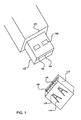
- Fig. 1 shows an example of a USB plug and socket.
- a USB plug 100 a rectangular metal housing 102 has holes 104 located on the wide side of metal housing 102.
- plug pins 106 Located inside metal housing 102 are plug pins 106, which reside a surface of substrate 108 (i.e., the downward-facing surface due to the orientation of the USB plug in Fig. 1 ).
- receptacle shell 112 On a USB socket 110, receptacle shell 112 has leaf springs 114 located on the wide side of a rectangular receptacle shell 112. At the end of each leaf spring 104 is a tip 116, which is designed to engage with a hole 104 when plug 100 is fully inserted into socket 110. The contact point may also be elsewhere, such as on a bend on the leaf spring.
- socket pins 118 Inside receptacle shell 112 are socket pins 118 residing on a substrate 120. Socket pins 118 are configured to mate with plug pins 106 when USB plug 100 is inserted into USB socket 110.
- Friction force allows USB plug 100 to stay mated with USB socket 110. Friction force is created when socket pins 118 make contact with plug pins 106. Friction force is also produced when leaf springs 114 slides along metal housing 102. Yet another source of friction force occurs when tips 116 are lodged inside holes 104.
- a USB plug may be protected from environmental damage by capping it with a USB cap.
- a USB cap may be made of plastic or rubber or a similarly suitable material, typically without a metallic receptacle shell. The USB cap generally relies on friction to keep the cap engaged with the USB plug tip.
- USB device it has been found that friction force alone is insufficient in keeping some USB devices connected to their USB hosts or USB caps. If the USB device is not securely connected to the USB host, the USB device may be easily disconnected unintentionally, e.g., when the USB host and USB device combination is accidentally bumped. If the USB device is intended to be a portable device, the USB device may be inadvertently separated from its USB cap or from its USB host when subjected to movement, for example. In either of the above examples, the result is an unintended and undesirable separation and/or possible loss and/or damage to the USB host, the USB device, or both.
- US 6,056,578 discloses a universal serial bus connector including a male and a female connector.
- the male connector has elastic hooking means fixed to two sides of its casing.
- the hooking means each has a front hook and an outward projected elastic rear push portion.
- Thefemale connector has outward extended retaining tabs provided at two edges of its each insertion hole corresponding to the hooks of the hooking means on the male connector.
- US 4,610,496 discloses a mechanical interlock system using ball detents for interlocking the first and second connector halves of an electrical connector assembly. In the preferred embodiment, two ball detents are utilized.
- the invention relates to a Universal Serial Bus socket-equipped arrangement (USB-SEA) configured for mating with a Universal Serial Bus (USB) plug having a plug metal housing and an aperture disposed in the plug metal housing.
- the arrangement includes a plug-receiving cavity configured to receive the USB plug.
- the arrangement further includes a spring-loaded mechanism disposed within the plug-receiving cavity.
- the spring-loaded mechanism is biased toward an interior region of the plug-receiving cavity.
- the spring-loaded mechanism is also configured to slide along the connector metal housing of the USB plug when the USB plug is inserted into the plug-receiving cavity and to movably mate with the aperture disposed in the plug metal housing when the USB plug is in a terminal mating position with the USB socket assembly.
- the spring-loaded mechanism represents one of a spring-loaded ball and a spring-loaded pin.
- the invention also relates to a Universal Serial Bus (USB) coupling arrangement.
- the arrangement includes a portable USB device having a USB plug.
- the USB plug has therein a plurality of plug pins.
- the USB plug also includes a plug metal housing surrounding the plurality of plug pins, at least one surface of the plug metal housing having therein an aperture.
- the arrangements further includes a USB socket-equipped arrangement (USB-SEA) having therein a plug-receiving-cavity.
- the plug-receiving cavity includes a spring-loaded mechanism configured to bias against the plug metal housing.
- the spring-loaded mechanism represents one of a spring-loaded ball and a spring-loaded pin.
- the spring-loaded mechanism is configured to slide along the plug metal housing when the USB plug is inserted into the plug-receiving cavity and to movably mate with the aperture disposed in the plug metal housing when the USB plug is in a terminal mating position with the plug-receiving cavity.
- the invention also relates to a Universal Serial Bus (USB) coupling arrangement.
- the arrangement includes a USB plug having therein a plurality of plug pins.
- the USB plug includes a plug metal housing surrounding the plurality of plug pins.
- the plug metal housing includes a pair of first parallel surfaces and a pair of second parallel surfaces disposed perpendicular to the first parallel surfaces.
- the surface of the pair of second parallel surfaces is smaller than a surface of the pair of first parallel surfaces.
- At least one surface of the pair of second parallel surfaces has therein an aperture.
- the arrangement further includes a USB socket-equipped arrangement (USB-SEA) having therein a plug-receiving cavity.
- the plug-receiving cavity includes at least a first generally curved protrusion that is spring-loaded to bias against the plug metal housing.
- the first generally curved protrusion is configured to slide along the plug metal housing when the USB plug is inserted into the plug-receiving cavity and to movably mate with the aperture disposed in the plug metal housing when the USB plug is in a terminal mating position with the plug-receiving cavity.
- the invention also relates to a portable electronic system.
- a portable electronic device having a first plug, the first plug having therein a plurality of plug pins.
- the first plug includes plug housing surrounding the plurality of plug pins, at least one surface of the plug housing having therein an aperture.
- SEA first socket-equipped arrangement
- the plug-receiving cavity includes a spring-loaded mechanism configured to bias against the plug housing.
- the spring-loaded mechanism is one of a spring-loaded ball and a spring-loaded pin.
- the spring-loaded mechanism is configured to slide along the plug housing when the first plug is inserted into the plug-receiving cavity and to movably mate with the aperture disposed in the plug housing when the first plug is in a terminal mating position with the plug-receiving cavity.
- Fig. 1 shows an example of a prior art Universal Serial Bus (USB) plug and socket
- Fig. 2 shows, in accordance with an embodiment of the present invention, a USB cap, representing one type of USB socket-equipped arrangement (USB-SBA), along with a modified USB plug configured to movably mate with a coupling mechanism in the cap.
- USB-SBA USB socket-equipped arrangement
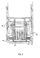
- Fig. 3 shows, in accordance with an embodiment of the invention, how the steel balls of the detent assemblies of the USB-SEA engage apertures in the USB plug housing.
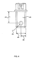
- Fig. 4 shows, in accordance with an embodiment of the invention, example dimensions of the USB plug, including the ball-receiving aperture.
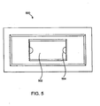
- Fig. 5 shows, in accordance with an embodiment of the invention, a view of the plug-receiving cavity of a cap 500, representing an example a USB-SEA.
- Fig. 6 shows, in accordance with an embodiment of the invention, an inventive electronic system that includes a host having a socket and a device having a plug, the host having a socket being coupled with the device having a plug using the generally curved detent mechanism and the plug aperture disclosed herein.
- the invention might also cover articles of manufacture that includes a computer readable medium on which computer-readable instructions for carrying out embodiments of the inventive technique are stored.
- the computer readable medium may include, for example, semiconductor, magnetic, optomagnetic, optical, or other forms of computer readable medium for storing computer readable code.
- the invention may also cover apparatuses for practicing embodiments of the invention. Such apparatus may include circuits, dedicated and/or programmable, to carry out tasks pertaining to embodiments of the invention. Examples of such apparatus include a general purpose computer and/or a dedicated computing device when appropriately programmed and may include a combination of a computer/computing devioe and dedicated/programmable circuits adapted for the various tasks pertaining to embodiments of the invention.
- USB-SEA Universal Serial Bus
- USB-SEA USB socket-equipped arrangement
- the USB plug is provided with at least one aperture, which is configured to mate with a generally curved protrusion located in the plug-receiving cavity of the USB-SEA.
- USB socket-equipped arrangement may include any USB host that can save, recall, transfer, and/or process data.
- a USB device may be plugged into other USB socket-equipped arrangements (USB-SEAs).
- USB-SEAs USB socket-equipped arrangements
- a battery park while not typically thought of as a USB host, may nevertheless have a USB socket to allow a USB device to obtain battery energy therefrom.
- a USB battery charger while not typically thought of as a USB host, may nevertheless have a USB socket to supply electrical charge to a rechargeable battery within the USB device.
- a display such as a portable or stationary display employing liquid crystal display technology or other display technologies
- a storage device such as a portable or stationary storage device employing hard disks or other storage technologies
- a remote control arrangement may include a first portion having a USB socket for mating with the USB plug of the USB device. The remote itself may communicate with this first portion using a signal-carrying wire or via a wireless approach. In these cases, power and/or signals (e.g., control, audio, video, data, etc.) are communicated between the USB-SEA and the USB device via one or more of the socket pins and one or more of the plug pins.
- a cap having a USB-like socket may be employed to protect the plug and the plug pins from environmental damage.
- a USB-SEA may include all the above examples and other arrangements having a plug-receiving cavity configured to mechanically and/or electronically mate with a USB plug.
- a USB-SEA may be either stationary or portable (e.g., capable of being carried or worn by the human user).
- portable USB entertainment and/or communication devices such as the popular iPODTM devices, available from Apple Computer, Inc. of Cupertino, CA
- a USB-SEA such as a USB cap, oftentimes includes a lanyard to allow the user to wear the USB device when the USB device is plugged into the USB-SEA.
- the plug-receiving cavity of the USB-SEA may represent a USB socket having a rectangular metallic housing and a socket pin-bearing substrate.
- the plug-receiving cavity of the USB-SEA may also represent, for example, the recess in a USB cap into which the USB plug may be inserted.
- the generally curved protrusion is designed to easily accommodate the initial insertion of the USB plug tip and to slide along the metal housing of the USB plug prior to positively engaging with the aperture. Further, the generally curved protrusion is biased against the metal housing of the USB socket by a biasing means, such as a coil spring. Since different coil springs can be manufactured with different biasing forces, it is possible for a USB socket to accommodate different USB devices simply by replacing one coil spring with another coil spring to achieve a higher or lower engaging/disengaging force.
- a positive tactile feedback is provided.
- the positive tactile feedback provides the user with a secure feeling that the USB plug and USB-SEA is fully engaged and the generally curved protrusion of the USB-SEA has positively engaged with the aperture in the metal housing of the USB plug.
- the distance between the USB plug aperture that accepts the generally curved protrusion of the USB-SEA and the start of the plug overmold portion is matched with the distance between the generally curved protrusion of the USB-SEA and opening of the plug-receiving cavity of the USB-SEA so that when the USB plug is fully inserted into the USB-SEA and the aperture in the USB plug engages the generally curved protrusion in the USB-SEA, there is visually substantially no gap between the start of the plug overmold portion of the USB plug and the opening of the plug-receiving cavity of the USB-SEA. The closing of this gap provides a visual confirmation that the USB plug is securely mated with the USB-SEA.
- no external collar arrangement is required on or near the socket to retract the generally curved protrusion in order to facilitate insertion and full engagement of the USB plug and the USB-SEA.
- This feature enhances user-friendliness since there may be no space on or around the USB-SEA to accommodate an external collar. Even if there is space, such a collar may be too small and uncomfortable for users with large fingers.
- the retraction of the generally curved protrusion e.g., steel ball
- the retraction of the generally curved protrusion is automatic upon insertion of the USB plug into the USB-SEA and such automatic retraction is sufficient to allow the full engagement of the USB plug and the USB-SEA when the USB plug is in its terminal coupling position.
- the retraction of the generally curved protrusion e.g., steel ball
- the generally curved protrusion may slide along the plug housing until the USB plug and the socket are apart.
- Fig. 2 shows, in accordance with an embodiment of the present invention, a USB plug and a USB cap, with the USB cap representing one type of USB-SEA.
- a metal housing 202 comprises of two pairs of parallel surfaces.
- a first pair of parallel surfaces 204 is perpendicular to a second pair of parallel surfaces 206.
- an aperture (i.e., retention hole) 208 Located on at least one side of the second pair of parallel surfaces 206 is an aperture (i.e., retention hole) 208.
- plug pins 210 Located inside metal housing 202 are plug pins 210, which reside on top of a substrate 212.
- a ball detent assembly 224 houses a coil spring and a steel ball, with the coil spring biasing the steel ball in the direction into the plug-receiving cavity of the USB-SEA.
- Ball detent assembly 224 is essentially a tube with one closed end and a constricted open end that is designed to snugly capture the steel ball in a position such that at least a portion of the steel ball protrudes from the open end of the ball detent assembly. This arrangement is shown in greater detail in Fig. 3 herein.
- Ball detent assembly 224 may be ultrasonically welded into cavity 226 in inner cap 222. There are other ways that ball detent assembly 224 may be coupled with cavity 226. These methods may include, but are not limited to, glued in, pressed in, heat-processed, heat-sinked, etc. In a preferred embodiment, there are two ball detent assemblies 224, one on each side of inner cap 222.
- Fig. 3 shows, in an embodiment of the invention, how the steel balls of the detent assemblies engage apertures in the USB plug housing. In Fig.
- a steel ball 306 is disposed inside a detent assembly 302.
- Detent assembly 302 includes a coil spring 304 that pushes against a ball 306.
- steel ball 306 represents a generally curved protrusion for engaging with a corresponding aperture in the USB plug housing
- coil spring 304 represents a biasing mechanism for biasing the generally curved protrusion against the USB plug housing when the USB plug is inserted into the plug-receiving cavity in the USB-SEA.
- spring-loaded ball 306 is configured to bias toward the interior region of the plug receiving cavity and against a plug metal housing 308 when the USB plug is inserted into the plug-receiving cavity of the USB-SEA.
- plug metal housing 308 causes ball 306 to travel outward (e.g., retracts) and compress against coil springs 304.
- the amount of pressure that ball 306 exerts against coil spring 304 lessens when ball 306 mates with aperture 314 in metal housing 308 of the USB plug.
- the amount of disengagement force is configurable by simply selecting the appropriate biasing device (e.g., the coil spring) that provides the desired biasing force.
- Fig. 3 also shows that once the USB plug is in the terminal mating position with the plug-receiving cavity of the USB-SEA, there is substantially no gap between the overmold portion of the USB plug and the opening of the plug-receiving cavity of the USB-SEA.
- the closure of the gap (shown in Fig. 3 by reference number 322) is achieved by designing the USB plug tip, the USB plug overmold, the aperture in the USB plug metal housing, the depth of the plug-receiving cavity of the USB-SEA, and location of the biasing ball with the appropriate dimensions. This closure advantageously provides a positive visual feedback to the user that positive engagement has taken place.
- ball 306 may be located on each side of plug-receiving cavity of the USB-SEA. Further, aperture 314 may be located on each side of plug metal housing 308. Thus, when the USB plug is inserted into the plug-receiving cavity of the USB-SEA, the ball on each of the plug-receiving cavity of the USB-SEA mates with the aperture located on each side of the plug metal housing.
- the balls in the plug-receiving cavity of the USB-SEA and their corresponding apertures in the USB plug housing are alternatives to, or preferably additions to, the prior art leaf springs/tips and corresponding holes (e.g., leaf springs 104/tips 106 and corresponding holes 104 of Fig. 1 ). Accordingly, the combination of ball 306/aperture 314 increases the force requires to disengage the USB from its USB-SEA.
- the biasing ball/corresponding aperture combination not only replaces the prior art leaf spring/tip and corresponding hole but further allows the plug-receiving cavity of USB-SEA to be formed of any material, even resilient materials such as soft plastic or hard rubber since the function of positively engaging the apertures in the plug metal housing is provided by the biasing ball and not by leaf spring/tip molded from the same material that forms the plug-receiving cavity of the USB-SEA.
- a removable (i.e., not integrally molded) biasing arrangement such as coil spring 3 04 allows the manufacturer to employ different coil springs to achieve different biasing force.
- Fig. 4 shows, in an embodiment of the invention, example dimensions of the USB plug, including the ball-receiving aperture.
- Distance 402 which is the distance from start of the overmold portion of the USB plug to the center of the aperture, is about 9.96 millimeter with a tolerance of about 0.05 millimeter.
- Distance 404 which is the diameter of the aperture, is about 1.60 millimeter with a tolerance of about 0.10 millimeter.
- Distance 406 which is the thickness of the USB plug (i.e., the distance between the two wider parallel surfaces of the plug metal housing), is about 4:50 millimeter with a tolerance of about 0.05 millimeter.
- Fig. 5 shows, in an embodiment of the invention, a view of the plug-receiving cavity of a cap 500, representing an example USB-SEA.
- the view of Fig. 5 is directly into the plug-receiving cavity, from the direction of USB plug insertion.
- Plug-receiving cavity 502 may be formed of any suitable material and is dimensioned to snugly fit the USB plug metal housing.
- Ball 504 is about 2 millimeter in diameter with a 0.5 millimeter protrusion inside the plug-receiving cavity.
- the ball 504 may be made of highly polished stainless steel and/or may have a different dimension depending on applications.
- the USB plug may be part of an electronic entertainment device, which is configured to play electronically stored music (i.e., MP3 player).
- the USB plug may mate with a USB cap that may be coupled to a lanyard. This coupling arrangement allows the user to wear the USB electronic entertainment device around his neck, via the lanyard cap, without fear of unexpected disengagement.
- the electronic entertainment device may mate with a plug-receiving cavity that is coupled to a human attachment arrangement.
- the human attachment arrangement i.e., armband
- the human attachment arrangement is configured to be worn by the user.
- the user may insert the electronic entertainment device into the armband and proceed to enjoy the electronic entertainment device without fearing that the electronic entertainment device might inadvertently become disengaged from the armband through normal activities. For example, a runner can enjoy listening to his favorite songs playing on an MP3 player, which is attached to an armband, without worrying that the MP3 player may accidentally become disengaged.
- the USB plug may be part of an electronic image-capturing device (i.e., pen scanner). Similar to the electronic entertainment device, the electronic image-capturing device may be connected to a USB socket, which may be part of a lanyard cap or a human attachment arrangement (i.e., armband). In either case, the user may insert the electronic image-capturing device into the USB socket without fearing that the electronic image-capturing device may unintentionally disengage from the USB socket.
- a USB socket which may be part of a lanyard cap or a human attachment arrangement (i.e., armband).
- the user may insert the electronic image-capturing device into the USB socket without fearing that the electronic image-capturing device may unintentionally disengage from the USB socket.
- Fig. 6 shows, in accordance with an embodiment of the invention, an inventive electronic system that includes a host having a socket and a device having a plug, the host having a socket being coupled with the device having a plug using the generally curved detent mechanism and the plug aperture disclosed herein.
- the host having a socket may represent any electronic or electrical sub-system (e.g., a display, an external hard disk, an external storage device, a battery pack, a charger, etc.)
- the device having a plug may represent any electronic or electrical sub-system (e.g., a portable audio player, a portable video player, a portable memory device, etc.) that is configured to be coupled to the host via the plug and the socket.
- the plug and the socket are endowed with apertures and detent mechanisms in the manner discussed herein. Note that although the preferred or disclosed embodiment refers to the USB plug and the USB socket, it is possible that the plug and socket may be configured for use with other protocols.
- embodiments of the invention offer more secure mating arrangements and requires a greater disengagement force to disengage the USB plug from the plug-receiving cavity of the USB-SEA. Since the biasing mechanism (e.g., the coil spring) may be selected to suit the biasing and disengagement force requirements of a particular application, embodiments of the present invention allows the manufacturer to efficiently customize a USB-SEA to a variety of USB devices.
- the biasing mechanism e.g., the coil spring
- the positive "snapping" action of the ball into its corresponding aperture as the USB plug is fully inserted into the plug-receiving aperture offers a positive tactile and/or audible feedback to the user, giving the user a heightened sense of confidence that positive engagement has taken place.
- the closure of the gap between the plug overmold and the opening of the plug-receiving cavity of the USB-SEA provides a positive visual feedback to the user that positive engagement has taken place.
- the generally curved protrusion is disclosed in the specific example as a steel ball, such generally curved protrusion may be formed of any suitably hard material, including various metals and plastics. Further, the generally curved protrusion may not be balls at all. As long as the mechanism that engages the aperture has a sloped surface (which may be concave or convex) to allow a force pulling the USB plug and the USB-SEA apart to "slide" the mechanism out of the aperture, positive engagement and disengagement in accordance with principles of the present invention are achieved. For example, a pin with a rounded end may be employed in place of the ball.
- the biasing mechanism can be any alternative to a coil spring, such as a removable leaf spring, that provides a biasing force to the generally curved protrusion.
- the biasing mechanism does not need to be disposed in the detent mechanism of Fig. 3 . As long as the biasing mechanism and the generally curved protrusion are attached to the USB-SEA in some way to allow the generally curved protrusion to engage with the aperture in the USB plug housing, positive engagement and disengagement in accordance with principles of the present invention are achieved.
- the generally curved protrusion may be made of a suitable non-metallic material if desired.
- the metal housing surrounding the plug pins may be replaced by another suitable non-metallic housing.
- the mechanism for positively coupling the plug to the socket (and by extension, the plug-including sub-system to the socket-including sub-system) may be applied to plugs and sockets adapted for use with protocols other than the USB protocol.
Landscapes
- Details Of Connecting Devices For Male And Female Coupling (AREA)
- Connector Housings Or Holding Contact Members (AREA)
- Coupling Device And Connection With Printed Circuit (AREA)
- Communication Cables (AREA)
- Information Transfer Systems (AREA)
Applications Claiming Priority (2)
| Application Number | Priority Date | Filing Date | Title |
|---|---|---|---|
| US64379205P | 2005-01-07 | 2005-01-07 | |
| EP06717602A EP1834384B1 (en) | 2005-01-07 | 2006-01-06 | Universal serial bus connector and socket coupling arrangements |
Related Parent Applications (1)
| Application Number | Title | Priority Date | Filing Date |
|---|---|---|---|
| EP06717602.4 Division | 2006-01-06 |
Publications (2)
| Publication Number | Publication Date |
|---|---|
| EP2246941A1 EP2246941A1 (en) | 2010-11-03 |
| EP2246941B1 true EP2246941B1 (en) | 2012-03-14 |
Family
ID=36143284
Family Applications (2)
| Application Number | Title | Priority Date | Filing Date |
|---|---|---|---|
| EP10171284A Expired - Lifetime EP2246941B1 (en) | 2005-01-07 | 2006-01-06 | Connector and socket coupling arrangements |
| EP06717602A Expired - Lifetime EP1834384B1 (en) | 2005-01-07 | 2006-01-06 | Universal serial bus connector and socket coupling arrangements |
Family Applications After (1)
| Application Number | Title | Priority Date | Filing Date |
|---|---|---|---|
| EP06717602A Expired - Lifetime EP1834384B1 (en) | 2005-01-07 | 2006-01-06 | Universal serial bus connector and socket coupling arrangements |
Country Status (7)
| Country | Link |
|---|---|
| US (1) | US7384295B2 (enExample) |
| EP (2) | EP2246941B1 (enExample) |
| JP (1) | JP4555349B2 (enExample) |
| CN (2) | CN102324651A (enExample) |
| AT (2) | ATE499727T1 (enExample) |
| DE (1) | DE602006020241D1 (enExample) |
| WO (1) | WO2006074348A1 (enExample) |
Cited By (1)
| Publication number | Priority date | Publication date | Assignee | Title |
|---|---|---|---|---|
| DE102012217465A1 (de) * | 2012-09-26 | 2014-03-27 | Tyco Electronics Amp Gmbh | Elektromagnetische Schirmung sowie elektrischer, elektronischer oder elektrooptischer Verbinder |
Families Citing this family (53)
| Publication number | Priority date | Publication date | Assignee | Title |
|---|---|---|---|---|
| US7540754B2 (en) | 2006-01-06 | 2009-06-02 | Apple Inc. | Universal Serial Bus plug and socket coupling arrangements |
| US20070016957A1 (en) * | 2005-07-18 | 2007-01-18 | Seaward Karen L | Secure portable memory mouse device |
| US8628345B2 (en) * | 2007-04-04 | 2014-01-14 | Ppc Broadband, Inc. | Releasably engaging high definition multimedia interface plug |
| US7857652B2 (en) * | 2007-04-04 | 2010-12-28 | John Mezzalingua Associates, Inc. | Releasably engaging high definition multimedia interface plug |
| US7892014B2 (en) * | 2007-04-04 | 2011-02-22 | John Mezzalingua Associates, Inc. | Releasably engaging high definition multimedia interface plug |
| US7476118B2 (en) * | 2007-04-04 | 2009-01-13 | John Mezzalingua Assoc., Inc. | Releasably engaging high definition multimedia interface plug |
| US7862367B2 (en) * | 2007-04-04 | 2011-01-04 | John Mezzalingua Associates, Inc. | Releasably engaging high definition multimedia interface plug |
| US20080291787A1 (en) * | 2007-05-22 | 2008-11-27 | Summer Lane Bruns | Audio cassette adapter with cable and connector storage in the body of cassette |
| JP2008299532A (ja) * | 2007-05-30 | 2008-12-11 | Toshiba Corp | 電子機器 |
| US20090210609A1 (en) * | 2008-02-04 | 2009-08-20 | Iain Thomas Learmonth | Wireless USB hub |
| KR100946777B1 (ko) | 2008-02-04 | 2010-03-11 | 백창욱 | 유에스비 연결플러그용 뚜껑 구조 |
| US7540786B1 (en) * | 2008-04-17 | 2009-06-02 | Hon Hai Precision Ind. Co., Ltd. | Flash memory device with improved contact arrangement |
| US7635280B1 (en) | 2008-07-30 | 2009-12-22 | Apple Inc. | Type A USB receptacle with plug detection |
| US20100124942A1 (en) * | 2008-11-20 | 2010-05-20 | Raytac Corp. | Combination electronic card and wireless transceiver with touch control and remote control functions |
| JP2010251319A (ja) | 2009-04-15 | 2010-11-04 | Chou Hsien Tsai | 双方向電気的連接が可能なソケット構造 |
| US8142212B2 (en) | 2009-06-10 | 2012-03-27 | Imation Corp. | Locking mechanisms and locking caps for USB connectors |
| MX343361B (es) | 2010-05-28 | 2016-11-03 | Apple Inc | Conector de orientacion dual con contactos externos. |
| EP2577812A4 (en) | 2010-05-28 | 2014-12-17 | Apple Inc | D-SHAPED CONNECTOR |
| US9124048B2 (en) | 2010-06-09 | 2015-09-01 | Apple Inc. | Flexible TRS connector |
| EP2583356A4 (en) | 2010-06-18 | 2015-04-22 | Apple Inc | DOUBLE DIRECTION CONNECTOR WITH SIDE CONTACTS |
| US8911260B2 (en) | 2010-06-21 | 2014-12-16 | Apple Inc. | External contact plug connector |
| TWI492463B (zh) * | 2010-06-21 | 2015-07-11 | Apple Inc | 外部接觸插頭連接器 |
| JP5578339B2 (ja) * | 2010-11-05 | 2014-08-27 | 株式会社安川電機 | 制御装置 |
| US8539125B1 (en) * | 2011-02-18 | 2013-09-17 | Michael Ford | Combined USB flash drive cap audio device |
| US8684760B1 (en) | 2011-03-25 | 2014-04-01 | Google Inc. | Power cord with anti-theft assembly |
| US8708745B2 (en) | 2011-11-07 | 2014-04-29 | Apple Inc. | Dual orientation electronic connector |
| US9112327B2 (en) | 2011-11-30 | 2015-08-18 | Apple Inc. | Audio/video connector for an electronic device |
| CN202435073U (zh) * | 2011-12-26 | 2012-09-12 | 鸿富锦精密工业(深圳)有限公司 | 充电电池及使用该充电电池的电源系统 |
| CN104247164A (zh) * | 2012-04-26 | 2014-12-24 | 株式会社安川电机 | 控制装置 |
| CA145803S (en) * | 2012-05-22 | 2013-02-19 | Spector & Co | Journal with strap |
| USD684539S1 (en) | 2012-07-06 | 2013-06-18 | Apple Inc. | Connector |
| USD960106S1 (en) | 2012-07-06 | 2022-08-09 | Apple Inc. | Connector |
| USD731434S1 (en) | 2012-07-06 | 2015-06-09 | Apple Inc. | Connector |
| USD684976S1 (en) | 2012-09-07 | 2013-06-25 | Jody Akana | Adapter |
| KR20140024626A (ko) * | 2012-08-20 | 2014-03-03 | 타이코에이엠피(유) | 커넥터 모듈 |
| US8777666B2 (en) | 2012-09-07 | 2014-07-15 | Apple Inc. | Plug connector modules |
| USD699188S1 (en) | 2012-09-11 | 2014-02-11 | Apple Inc. | Adapter |
| US9093803B2 (en) | 2012-09-07 | 2015-07-28 | Apple Inc. | Plug connector |
| USD781785S1 (en) | 2012-09-11 | 2017-03-21 | Apple Inc. | Adapter |
| US9160129B2 (en) | 2012-09-11 | 2015-10-13 | Apple Inc. | Connectors and methods for manufacturing connectors |
| WO2014040231A1 (en) | 2012-09-11 | 2014-03-20 | Apple Inc. | Connectors and methods for manufacturing connectors |
| US9059531B2 (en) | 2012-09-11 | 2015-06-16 | Apple Inc. | Connectors and methods for manufacturing connectors |
| US9325097B2 (en) | 2012-11-16 | 2016-04-26 | Apple Inc. | Connector contacts with thermally conductive polymer |
| US20140206209A1 (en) | 2013-01-24 | 2014-07-24 | Apple Inc. | Reversible usb connector |
| CN103633490B (zh) * | 2013-11-28 | 2015-09-30 | 四川航天计量测试研究所 | 一种无锁紧组件的连接器可靠插接机构及其装配方法和对接方法 |
| DE102013017989A1 (de) * | 2013-11-29 | 2015-06-03 | Neutrik Ag | Steckerteil |
| JP6265770B2 (ja) | 2014-02-13 | 2018-01-24 | 日本航空電子工業株式会社 | コネクタ |
| CN105337058B (zh) * | 2014-07-16 | 2018-02-09 | 珠海格力节能环保制冷技术研究中心有限公司 | 压缩机的接线柱结构及压缩机 |
| CN105047218A (zh) * | 2015-07-20 | 2015-11-11 | 中山火炬职业技术学院 | 多usb头可换的u盘 |
| CN106207615B (zh) * | 2016-07-29 | 2019-06-07 | 中航光电科技股份有限公司 | 连接器及其锁紧杆组件和锁紧杆 |
| CN106786982A (zh) * | 2017-01-24 | 2017-05-31 | 西安易朴通讯技术有限公司 | 一种适用于终端的充电装置 |
| CN109149264B (zh) * | 2017-06-28 | 2021-01-29 | 中航光电科技股份有限公司 | 一种连接器组件及其连接器 |
| CN108058661A (zh) * | 2017-12-25 | 2018-05-22 | 芜湖宏景电子股份有限公司 | 一种防折损的车载usb接口结构 |
Family Cites Families (14)
| Publication number | Priority date | Publication date | Assignee | Title |
|---|---|---|---|---|
| US4610496A (en) * | 1985-05-24 | 1986-09-09 | Flight Connector Corporation | Connector mechanical interlock using ball detents |
| JPH03106234U (enExample) * | 1990-02-09 | 1991-11-01 | ||
| CN2064949U (zh) * | 1990-03-01 | 1990-10-31 | 彭璞玉 | 动触式电源插座 |
| JPH06163109A (ja) * | 1992-11-19 | 1994-06-10 | Nec Eng Ltd | コネクタのロック機構 |
| US5580268A (en) * | 1995-03-31 | 1996-12-03 | Molex Incorporated | Lockable electrical connector |
| US5658170A (en) * | 1995-09-26 | 1997-08-19 | Hon Hai Precision Ind. Co., Ltd. | Cable connector assembly |
| US5772461A (en) * | 1996-09-13 | 1998-06-30 | Hon Hai Precision Ind. Co., Ltd. | Locking mechanism for interconnecting two mated connectors |
| US6056578A (en) * | 1998-01-13 | 2000-05-02 | Advanced-Connectek, Inc. | Universal serial bus connector |
| JP2003243093A (ja) * | 2002-02-21 | 2003-08-29 | Yazaki Corp | Usbコネクタ |
| JP2003282178A (ja) | 2002-03-26 | 2003-10-03 | Mitsumi Electric Co Ltd | Usb雄コネクタ付き小型機器 |
| JP2004335275A (ja) * | 2003-05-08 | 2004-11-25 | Fuji Photo Film Co Ltd | コネクタ抜止装置 |
| JP4068029B2 (ja) * | 2003-05-28 | 2008-03-26 | タイコエレクトロニクスアンプ株式会社 | 電気コネクタ組立体、リセプタクルコネクタおよびプラグコネクタ |
| US7125273B2 (en) * | 2004-06-08 | 2006-10-24 | Advance Thermo Control, Ltd. | Detachable power cord apparatus |
| US20060134962A1 (en) * | 2004-12-17 | 2006-06-22 | Ming-Hsiang Yeh | Protection device for USB connector |
-
2006
- 2006-01-06 EP EP10171284A patent/EP2246941B1/en not_active Expired - Lifetime
- 2006-01-06 CN CN2011102748600A patent/CN102324651A/zh active Pending
- 2006-01-06 DE DE602006020241T patent/DE602006020241D1/de not_active Expired - Lifetime
- 2006-01-06 EP EP06717602A patent/EP1834384B1/en not_active Expired - Lifetime
- 2006-01-06 CN CN2006800016408A patent/CN101091292B/zh not_active Expired - Fee Related
- 2006-01-06 WO PCT/US2006/000427 patent/WO2006074348A1/en not_active Ceased
- 2006-01-06 US US11/327,819 patent/US7384295B2/en not_active Expired - Fee Related
- 2006-01-06 AT AT06717602T patent/ATE499727T1/de not_active IP Right Cessation
- 2006-01-06 AT AT10171284T patent/ATE549773T1/de active
- 2006-01-06 JP JP2007550489A patent/JP4555349B2/ja not_active Expired - Fee Related
Cited By (2)
| Publication number | Priority date | Publication date | Assignee | Title |
|---|---|---|---|---|
| DE102012217465A1 (de) * | 2012-09-26 | 2014-03-27 | Tyco Electronics Amp Gmbh | Elektromagnetische Schirmung sowie elektrischer, elektronischer oder elektrooptischer Verbinder |
| DE102012217465B4 (de) * | 2012-09-26 | 2016-09-15 | Te Connectivity Germany Gmbh | Elektromagnetische Schirmung sowie elektrischer, elektronischer oder elektrooptischer Verbinder |
Also Published As
| Publication number | Publication date |
|---|---|
| EP1834384A1 (en) | 2007-09-19 |
| DE602006020241D1 (de) | 2011-04-07 |
| ATE499727T1 (de) | 2011-03-15 |
| US20060172599A1 (en) | 2006-08-03 |
| HK1106877A1 (en) | 2008-03-20 |
| CN102324651A (zh) | 2012-01-18 |
| CN101091292B (zh) | 2011-11-23 |
| JP2008527651A (ja) | 2008-07-24 |
| EP2246941A1 (en) | 2010-11-03 |
| CN101091292A (zh) | 2007-12-19 |
| JP4555349B2 (ja) | 2010-09-29 |
| HK1149639A1 (en) | 2011-10-07 |
| ATE549773T1 (de) | 2012-03-15 |
| US7384295B2 (en) | 2008-06-10 |
| EP1834384B1 (en) | 2011-02-23 |
| WO2006074348A1 (en) | 2006-07-13 |
Similar Documents
| Publication | Publication Date | Title |
|---|---|---|
| EP2246941B1 (en) | Connector and socket coupling arrangements | |
| US7641498B2 (en) | Universal serial bus plug and receptacle coupling arrangements | |
| US8911260B2 (en) | External contact plug connector | |
| US7500882B2 (en) | Releasable connector system | |
| TWI502831B (zh) | 插頭連接器模組 | |
| US20140227895A1 (en) | Secure and/or lockable connecting arragement for video game system | |
| CN103794943A (zh) | 电连接器、托座及电连接器组件 | |
| US20120178279A1 (en) | Connector receptacle housings having reduced-wear finger contacts and reduced seam visibility | |
| TWM482180U (zh) | 插頭連接器結構 | |
| TWM541654U (zh) | 用於連接器之可撓性及斷開機構 | |
| TWM326725U (en) | Connector structure for vehicle | |
| US20150270657A1 (en) | Reversible electrical connector | |
| CN111224263A (zh) | 双向双面电连接器 | |
| CN213151707U (zh) | 无线充电器 | |
| HK1149639B (en) | Connector and socket coupling arrangements | |
| HK1106877B (en) | Universal serial bus connector and socket coupling arrangements | |
| JP2003168527A (ja) | 電気コネクタ | |
| US20080261461A1 (en) | Electrical connector assembly | |
| US20090113103A1 (en) | Cascade type charge assembly | |
| CN204230540U (zh) | 电连接器 | |
| CN215451986U (zh) | 磁吸音频转接头 | |
| CN204538356U (zh) | 用于电子设备的母座和电子设备 | |
| CN201479484U (zh) | 改良式扣接结构与其存储体 | |
| WO2025104053A1 (en) | Audio-player for children | |
| CN119742614A (zh) | 隐藏式浅深度插口 |
Legal Events
| Date | Code | Title | Description |
|---|---|---|---|
| PUAI | Public reference made under article 153(3) epc to a published international application that has entered the european phase |
Free format text: ORIGINAL CODE: 0009012 |
|
| 17P | Request for examination filed |
Effective date: 20100729 |
|
| AC | Divisional application: reference to earlier application |
Ref document number: 1834384 Country of ref document: EP Kind code of ref document: P |
|
| AK | Designated contracting states |
Kind code of ref document: A1 Designated state(s): AT BE BG CH CY CZ DE DK EE ES FI FR GB GR HU IE IS IT LI LT LU LV MC NL PL PT RO SE SI SK TR |
|
| GRAP | Despatch of communication of intention to grant a patent |
Free format text: ORIGINAL CODE: EPIDOSNIGR1 |
|
| REG | Reference to a national code |
Ref country code: HK Ref legal event code: DE Ref document number: 1149639 Country of ref document: HK |
|
| RIC1 | Information provided on ipc code assigned before grant |
Ipc: H01R 13/627 20060101AFI20110906BHEP |
|
| RTI1 | Title (correction) |
Free format text: CONNECTOR AND SOCKET COUPLING ARRANGEMENTS |
|
| GRAS | Grant fee paid |
Free format text: ORIGINAL CODE: EPIDOSNIGR3 |
|
| GRAA | (expected) grant |
Free format text: ORIGINAL CODE: 0009210 |
|
| AC | Divisional application: reference to earlier application |
Ref document number: 1834384 Country of ref document: EP Kind code of ref document: P |
|
| AK | Designated contracting states |
Kind code of ref document: B1 Designated state(s): AT BE BG CH CY CZ DE DK EE ES FI FR GB GR HU IE IS IT LI LT LU LV MC NL PL PT RO SE SI SK TR |
|
| REG | Reference to a national code |
Ref country code: GB Ref legal event code: FG4D |
|
| REG | Reference to a national code |
Ref country code: AT Ref legal event code: REF Ref document number: 549773 Country of ref document: AT Kind code of ref document: T Effective date: 20120315 Ref country code: CH Ref legal event code: EP |
|
| REG | Reference to a national code |
Ref country code: IE Ref legal event code: FG4D |
|
| REG | Reference to a national code |
Ref country code: DE Ref legal event code: R096 Ref document number: 602006028257 Country of ref document: DE Effective date: 20120510 |
|
| REG | Reference to a national code |
Ref country code: NL Ref legal event code: VDEP Effective date: 20120314 |
|
| REG | Reference to a national code |
Ref country code: HK Ref legal event code: GR Ref document number: 1149639 Country of ref document: HK |
|
| PG25 | Lapsed in a contracting state [announced via postgrant information from national office to epo] |
Ref country code: LT Free format text: LAPSE BECAUSE OF FAILURE TO SUBMIT A TRANSLATION OF THE DESCRIPTION OR TO PAY THE FEE WITHIN THE PRESCRIBED TIME-LIMIT Effective date: 20120314 |
|
| LTIE | Lt: invalidation of european patent or patent extension |
Effective date: 20120314 |
|
| PG25 | Lapsed in a contracting state [announced via postgrant information from national office to epo] |
Ref country code: GR Free format text: LAPSE BECAUSE OF FAILURE TO SUBMIT A TRANSLATION OF THE DESCRIPTION OR TO PAY THE FEE WITHIN THE PRESCRIBED TIME-LIMIT Effective date: 20120615 Ref country code: LV Free format text: LAPSE BECAUSE OF FAILURE TO SUBMIT A TRANSLATION OF THE DESCRIPTION OR TO PAY THE FEE WITHIN THE PRESCRIBED TIME-LIMIT Effective date: 20120314 |
|
| REG | Reference to a national code |
Ref country code: AT Ref legal event code: MK05 Ref document number: 549773 Country of ref document: AT Kind code of ref document: T Effective date: 20120314 |
|
| PG25 | Lapsed in a contracting state [announced via postgrant information from national office to epo] |
Ref country code: CY Free format text: LAPSE BECAUSE OF FAILURE TO SUBMIT A TRANSLATION OF THE DESCRIPTION OR TO PAY THE FEE WITHIN THE PRESCRIBED TIME-LIMIT Effective date: 20120314 |
|
| PG25 | Lapsed in a contracting state [announced via postgrant information from national office to epo] |
Ref country code: SI Free format text: LAPSE BECAUSE OF FAILURE TO SUBMIT A TRANSLATION OF THE DESCRIPTION OR TO PAY THE FEE WITHIN THE PRESCRIBED TIME-LIMIT Effective date: 20120314 Ref country code: CZ Free format text: LAPSE BECAUSE OF FAILURE TO SUBMIT A TRANSLATION OF THE DESCRIPTION OR TO PAY THE FEE WITHIN THE PRESCRIBED TIME-LIMIT Effective date: 20120314 Ref country code: EE Free format text: LAPSE BECAUSE OF FAILURE TO SUBMIT A TRANSLATION OF THE DESCRIPTION OR TO PAY THE FEE WITHIN THE PRESCRIBED TIME-LIMIT Effective date: 20120314 Ref country code: RO Free format text: LAPSE BECAUSE OF FAILURE TO SUBMIT A TRANSLATION OF THE DESCRIPTION OR TO PAY THE FEE WITHIN THE PRESCRIBED TIME-LIMIT Effective date: 20120314 Ref country code: PL Free format text: LAPSE BECAUSE OF FAILURE TO SUBMIT A TRANSLATION OF THE DESCRIPTION OR TO PAY THE FEE WITHIN THE PRESCRIBED TIME-LIMIT Effective date: 20120314 Ref country code: BE Free format text: LAPSE BECAUSE OF FAILURE TO SUBMIT A TRANSLATION OF THE DESCRIPTION OR TO PAY THE FEE WITHIN THE PRESCRIBED TIME-LIMIT Effective date: 20120314 Ref country code: SE Free format text: LAPSE BECAUSE OF FAILURE TO SUBMIT A TRANSLATION OF THE DESCRIPTION OR TO PAY THE FEE WITHIN THE PRESCRIBED TIME-LIMIT Effective date: 20120314 Ref country code: IS Free format text: LAPSE BECAUSE OF FAILURE TO SUBMIT A TRANSLATION OF THE DESCRIPTION OR TO PAY THE FEE WITHIN THE PRESCRIBED TIME-LIMIT Effective date: 20120714 |
|
| PG25 | Lapsed in a contracting state [announced via postgrant information from national office to epo] |
Ref country code: PT Free format text: LAPSE BECAUSE OF FAILURE TO SUBMIT A TRANSLATION OF THE DESCRIPTION OR TO PAY THE FEE WITHIN THE PRESCRIBED TIME-LIMIT Effective date: 20120716 Ref country code: SK Free format text: LAPSE BECAUSE OF FAILURE TO SUBMIT A TRANSLATION OF THE DESCRIPTION OR TO PAY THE FEE WITHIN THE PRESCRIBED TIME-LIMIT Effective date: 20120314 |
|
| PLBE | No opposition filed within time limit |
Free format text: ORIGINAL CODE: 0009261 |
|
| STAA | Information on the status of an ep patent application or granted ep patent |
Free format text: STATUS: NO OPPOSITION FILED WITHIN TIME LIMIT |
|
| PG25 | Lapsed in a contracting state [announced via postgrant information from national office to epo] |
Ref country code: NL Free format text: LAPSE BECAUSE OF FAILURE TO SUBMIT A TRANSLATION OF THE DESCRIPTION OR TO PAY THE FEE WITHIN THE PRESCRIBED TIME-LIMIT Effective date: 20120314 Ref country code: DK Free format text: LAPSE BECAUSE OF FAILURE TO SUBMIT A TRANSLATION OF THE DESCRIPTION OR TO PAY THE FEE WITHIN THE PRESCRIBED TIME-LIMIT Effective date: 20120314 Ref country code: AT Free format text: LAPSE BECAUSE OF FAILURE TO SUBMIT A TRANSLATION OF THE DESCRIPTION OR TO PAY THE FEE WITHIN THE PRESCRIBED TIME-LIMIT Effective date: 20120314 |
|
| 26N | No opposition filed |
Effective date: 20121217 |
|
| REG | Reference to a national code |
Ref country code: DE Ref legal event code: R097 Ref document number: 602006028257 Country of ref document: DE Effective date: 20121217 |
|
| PG25 | Lapsed in a contracting state [announced via postgrant information from national office to epo] |
Ref country code: ES Free format text: LAPSE BECAUSE OF FAILURE TO SUBMIT A TRANSLATION OF THE DESCRIPTION OR TO PAY THE FEE WITHIN THE PRESCRIBED TIME-LIMIT Effective date: 20120625 |
|
| PG25 | Lapsed in a contracting state [announced via postgrant information from national office to epo] |
Ref country code: BG Free format text: LAPSE BECAUSE OF FAILURE TO SUBMIT A TRANSLATION OF THE DESCRIPTION OR TO PAY THE FEE WITHIN THE PRESCRIBED TIME-LIMIT Effective date: 20120614 |
|
| PG25 | Lapsed in a contracting state [announced via postgrant information from national office to epo] |
Ref country code: MC Free format text: LAPSE BECAUSE OF NON-PAYMENT OF DUE FEES Effective date: 20130131 |
|
| REG | Reference to a national code |
Ref country code: CH Ref legal event code: PL |
|
| REG | Reference to a national code |
Ref country code: IE Ref legal event code: MM4A |
|
| PG25 | Lapsed in a contracting state [announced via postgrant information from national office to epo] |
Ref country code: CH Free format text: LAPSE BECAUSE OF NON-PAYMENT OF DUE FEES Effective date: 20130131 Ref country code: LI Free format text: LAPSE BECAUSE OF NON-PAYMENT OF DUE FEES Effective date: 20130131 |
|
| PG25 | Lapsed in a contracting state [announced via postgrant information from national office to epo] |
Ref country code: IE Free format text: LAPSE BECAUSE OF NON-PAYMENT OF DUE FEES Effective date: 20130106 |
|
| PG25 | Lapsed in a contracting state [announced via postgrant information from national office to epo] |
Ref country code: TR Free format text: LAPSE BECAUSE OF FAILURE TO SUBMIT A TRANSLATION OF THE DESCRIPTION OR TO PAY THE FEE WITHIN THE PRESCRIBED TIME-LIMIT Effective date: 20120314 |
|
| PG25 | Lapsed in a contracting state [announced via postgrant information from national office to epo] |
Ref country code: LU Free format text: LAPSE BECAUSE OF NON-PAYMENT OF DUE FEES Effective date: 20130106 Ref country code: HU Free format text: LAPSE BECAUSE OF FAILURE TO SUBMIT A TRANSLATION OF THE DESCRIPTION OR TO PAY THE FEE WITHIN THE PRESCRIBED TIME-LIMIT; INVALID AB INITIO Effective date: 20060106 |
|
| REG | Reference to a national code |
Ref country code: FR Ref legal event code: PLFP Year of fee payment: 11 |
|
| REG | Reference to a national code |
Ref country code: FR Ref legal event code: PLFP Year of fee payment: 12 |
|
| REG | Reference to a national code |
Ref country code: FR Ref legal event code: PLFP Year of fee payment: 13 |
|
| PGFP | Annual fee paid to national office [announced via postgrant information from national office to epo] |
Ref country code: FR Payment date: 20191216 Year of fee payment: 15 |
|
| PGFP | Annual fee paid to national office [announced via postgrant information from national office to epo] |
Ref country code: DE Payment date: 20191224 Year of fee payment: 15 Ref country code: IT Payment date: 20200114 Year of fee payment: 15 Ref country code: GB Payment date: 20191230 Year of fee payment: 15 Ref country code: FI Payment date: 20200109 Year of fee payment: 15 |
|
| REG | Reference to a national code |
Ref country code: DE Ref legal event code: R119 Ref document number: 602006028257 Country of ref document: DE |
|
| REG | Reference to a national code |
Ref country code: FI Ref legal event code: MAE |
|
| GBPC | Gb: european patent ceased through non-payment of renewal fee |
Effective date: 20210106 |
|
| PG25 | Lapsed in a contracting state [announced via postgrant information from national office to epo] |
Ref country code: FI Free format text: LAPSE BECAUSE OF NON-PAYMENT OF DUE FEES Effective date: 20210106 Ref country code: FR Free format text: LAPSE BECAUSE OF NON-PAYMENT OF DUE FEES Effective date: 20210131 |
|
| PG25 | Lapsed in a contracting state [announced via postgrant information from national office to epo] |
Ref country code: GB Free format text: LAPSE BECAUSE OF NON-PAYMENT OF DUE FEES Effective date: 20210106 Ref country code: DE Free format text: LAPSE BECAUSE OF NON-PAYMENT OF DUE FEES Effective date: 20210803 |
|
| PG25 | Lapsed in a contracting state [announced via postgrant information from national office to epo] |
Ref country code: IT Free format text: LAPSE BECAUSE OF NON-PAYMENT OF DUE FEES Effective date: 20210106 |