EP2246294B1 - Control method for fuel reformer - Google Patents
Control method for fuel reformer Download PDFInfo
- Publication number
- EP2246294B1 EP2246294B1 EP08872309.3A EP08872309A EP2246294B1 EP 2246294 B1 EP2246294 B1 EP 2246294B1 EP 08872309 A EP08872309 A EP 08872309A EP 2246294 B1 EP2246294 B1 EP 2246294B1
- Authority
- EP
- European Patent Office
- Prior art keywords
- temperature
- cat
- catalyst
- reforming catalyst
- control
- Prior art date
- Legal status (The legal status is an assumption and is not a legal conclusion. Google has not performed a legal analysis and makes no representation as to the accuracy of the status listed.)
- Not-in-force
Links
Images


Classifications
-
- C—CHEMISTRY; METALLURGY
- C01—INORGANIC CHEMISTRY
- C01B—NON-METALLIC ELEMENTS; COMPOUNDS THEREOF; METALLOIDS OR COMPOUNDS THEREOF NOT COVERED BY SUBCLASS C01C
- C01B3/00—Hydrogen; Gaseous mixtures containing hydrogen; Separation of hydrogen from mixtures containing it; Purification of hydrogen
- C01B3/02—Production of hydrogen or of gaseous mixtures containing a substantial proportion of hydrogen
- C01B3/32—Production of hydrogen or of gaseous mixtures containing a substantial proportion of hydrogen by reaction of gaseous or liquid organic compounds with gasifying agents, e.g. water, carbon dioxide, air
- C01B3/34—Production of hydrogen or of gaseous mixtures containing a substantial proportion of hydrogen by reaction of gaseous or liquid organic compounds with gasifying agents, e.g. water, carbon dioxide, air by reaction of hydrocarbons with gasifying agents
- C01B3/38—Production of hydrogen or of gaseous mixtures containing a substantial proportion of hydrogen by reaction of gaseous or liquid organic compounds with gasifying agents, e.g. water, carbon dioxide, air by reaction of hydrocarbons with gasifying agents using catalysts
- C01B3/386—Catalytic partial combustion
-
- F—MECHANICAL ENGINEERING; LIGHTING; HEATING; WEAPONS; BLASTING
- F01—MACHINES OR ENGINES IN GENERAL; ENGINE PLANTS IN GENERAL; STEAM ENGINES
- F01N—GAS-FLOW SILENCERS OR EXHAUST APPARATUS FOR MACHINES OR ENGINES IN GENERAL; GAS-FLOW SILENCERS OR EXHAUST APPARATUS FOR INTERNAL COMBUSTION ENGINES
- F01N9/00—Electrical control of exhaust gas treating apparatus
-
- F—MECHANICAL ENGINEERING; LIGHTING; HEATING; WEAPONS; BLASTING
- F02—COMBUSTION ENGINES; HOT-GAS OR COMBUSTION-PRODUCT ENGINE PLANTS
- F02D—CONTROLLING COMBUSTION ENGINES
- F02D19/00—Controlling engines characterised by their use of non-liquid fuels, pluralities of fuels, or non-fuel substances added to the combustible mixtures
- F02D19/06—Controlling engines characterised by their use of non-liquid fuels, pluralities of fuels, or non-fuel substances added to the combustible mixtures peculiar to engines working with pluralities of fuels, e.g. alternatively with light and heavy fuel oil, other than engines indifferent to the fuel consumed
- F02D19/0626—Measuring or estimating parameters related to the fuel supply system
- F02D19/0628—Determining the fuel pressure, temperature or flow, the fuel tank fill level or a valve position
-
- F—MECHANICAL ENGINEERING; LIGHTING; HEATING; WEAPONS; BLASTING
- F02—COMBUSTION ENGINES; HOT-GAS OR COMBUSTION-PRODUCT ENGINE PLANTS
- F02D—CONTROLLING COMBUSTION ENGINES
- F02D19/00—Controlling engines characterised by their use of non-liquid fuels, pluralities of fuels, or non-fuel substances added to the combustible mixtures
- F02D19/06—Controlling engines characterised by their use of non-liquid fuels, pluralities of fuels, or non-fuel substances added to the combustible mixtures peculiar to engines working with pluralities of fuels, e.g. alternatively with light and heavy fuel oil, other than engines indifferent to the fuel consumed
- F02D19/0663—Details on the fuel supply system, e.g. tanks, valves, pipes, pumps, rails, injectors or mixers
- F02D19/0668—Treating or cleaning means; Fuel filters
- F02D19/0671—Means to generate or modify a fuel, e.g. reformers, electrolytic cells or membranes
-
- C—CHEMISTRY; METALLURGY
- C01—INORGANIC CHEMISTRY
- C01B—NON-METALLIC ELEMENTS; COMPOUNDS THEREOF; METALLOIDS OR COMPOUNDS THEREOF NOT COVERED BY SUBCLASS C01C
- C01B2203/00—Integrated processes for the production of hydrogen or synthesis gas
- C01B2203/02—Processes for making hydrogen or synthesis gas
- C01B2203/025—Processes for making hydrogen or synthesis gas containing a partial oxidation step
- C01B2203/0261—Processes for making hydrogen or synthesis gas containing a partial oxidation step containing a catalytic partial oxidation step [CPO]
-
- C—CHEMISTRY; METALLURGY
- C01—INORGANIC CHEMISTRY
- C01B—NON-METALLIC ELEMENTS; COMPOUNDS THEREOF; METALLOIDS OR COMPOUNDS THEREOF NOT COVERED BY SUBCLASS C01C
- C01B2203/00—Integrated processes for the production of hydrogen or synthesis gas
- C01B2203/10—Catalysts for performing the hydrogen forming reactions
- C01B2203/1041—Composition of the catalyst
- C01B2203/1047—Group VIII metal catalysts
-
- C—CHEMISTRY; METALLURGY
- C01—INORGANIC CHEMISTRY
- C01B—NON-METALLIC ELEMENTS; COMPOUNDS THEREOF; METALLOIDS OR COMPOUNDS THEREOF NOT COVERED BY SUBCLASS C01C
- C01B2203/00—Integrated processes for the production of hydrogen or synthesis gas
- C01B2203/10—Catalysts for performing the hydrogen forming reactions
- C01B2203/1041—Composition of the catalyst
- C01B2203/1082—Composition of support materials
-
- C—CHEMISTRY; METALLURGY
- C01—INORGANIC CHEMISTRY
- C01B—NON-METALLIC ELEMENTS; COMPOUNDS THEREOF; METALLOIDS OR COMPOUNDS THEREOF NOT COVERED BY SUBCLASS C01C
- C01B2203/00—Integrated processes for the production of hydrogen or synthesis gas
- C01B2203/16—Controlling the process
- C01B2203/1604—Starting up the process
-
- C—CHEMISTRY; METALLURGY
- C01—INORGANIC CHEMISTRY
- C01B—NON-METALLIC ELEMENTS; COMPOUNDS THEREOF; METALLOIDS OR COMPOUNDS THEREOF NOT COVERED BY SUBCLASS C01C
- C01B2203/00—Integrated processes for the production of hydrogen or synthesis gas
- C01B2203/16—Controlling the process
- C01B2203/1614—Controlling the temperature
- C01B2203/1619—Measuring the temperature
-
- C—CHEMISTRY; METALLURGY
- C01—INORGANIC CHEMISTRY
- C01B—NON-METALLIC ELEMENTS; COMPOUNDS THEREOF; METALLOIDS OR COMPOUNDS THEREOF NOT COVERED BY SUBCLASS C01C
- C01B2203/00—Integrated processes for the production of hydrogen or synthesis gas
- C01B2203/16—Controlling the process
- C01B2203/1614—Controlling the temperature
- C01B2203/1623—Adjusting the temperature
-
- F—MECHANICAL ENGINEERING; LIGHTING; HEATING; WEAPONS; BLASTING
- F01—MACHINES OR ENGINES IN GENERAL; ENGINE PLANTS IN GENERAL; STEAM ENGINES
- F01N—GAS-FLOW SILENCERS OR EXHAUST APPARATUS FOR MACHINES OR ENGINES IN GENERAL; GAS-FLOW SILENCERS OR EXHAUST APPARATUS FOR INTERNAL COMBUSTION ENGINES
- F01N2240/00—Combination or association of two or more different exhaust treating devices, or of at least one such device with an auxiliary device, not covered by indexing codes F01N2230/00 or F01N2250/00, one of the devices being
- F01N2240/30—Combination or association of two or more different exhaust treating devices, or of at least one such device with an auxiliary device, not covered by indexing codes F01N2230/00 or F01N2250/00, one of the devices being a fuel reformer
-
- F—MECHANICAL ENGINEERING; LIGHTING; HEATING; WEAPONS; BLASTING
- F01—MACHINES OR ENGINES IN GENERAL; ENGINE PLANTS IN GENERAL; STEAM ENGINES
- F01N—GAS-FLOW SILENCERS OR EXHAUST APPARATUS FOR MACHINES OR ENGINES IN GENERAL; GAS-FLOW SILENCERS OR EXHAUST APPARATUS FOR INTERNAL COMBUSTION ENGINES
- F01N2610/00—Adding substances to exhaust gases
- F01N2610/04—Adding substances to exhaust gases the substance being hydrogen
-
- F—MECHANICAL ENGINEERING; LIGHTING; HEATING; WEAPONS; BLASTING
- F01—MACHINES OR ENGINES IN GENERAL; ENGINE PLANTS IN GENERAL; STEAM ENGINES
- F01N—GAS-FLOW SILENCERS OR EXHAUST APPARATUS FOR MACHINES OR ENGINES IN GENERAL; GAS-FLOW SILENCERS OR EXHAUST APPARATUS FOR INTERNAL COMBUSTION ENGINES
- F01N2900/00—Details of electrical control or of the monitoring of the exhaust gas treating apparatus
- F01N2900/06—Parameters used for exhaust control or diagnosing
- F01N2900/16—Parameters used for exhaust control or diagnosing said parameters being related to the exhaust apparatus, e.g. particulate filter or catalyst
- F01N2900/1602—Temperature of exhaust gas apparatus
-
- F—MECHANICAL ENGINEERING; LIGHTING; HEATING; WEAPONS; BLASTING
- F01—MACHINES OR ENGINES IN GENERAL; ENGINE PLANTS IN GENERAL; STEAM ENGINES
- F01N—GAS-FLOW SILENCERS OR EXHAUST APPARATUS FOR MACHINES OR ENGINES IN GENERAL; GAS-FLOW SILENCERS OR EXHAUST APPARATUS FOR INTERNAL COMBUSTION ENGINES
- F01N2900/00—Details of electrical control or of the monitoring of the exhaust gas treating apparatus
- F01N2900/06—Parameters used for exhaust control or diagnosing
- F01N2900/16—Parameters used for exhaust control or diagnosing said parameters being related to the exhaust apparatus, e.g. particulate filter or catalyst
- F01N2900/1631—Heat amount provided to exhaust apparatus
-
- F—MECHANICAL ENGINEERING; LIGHTING; HEATING; WEAPONS; BLASTING
- F01—MACHINES OR ENGINES IN GENERAL; ENGINE PLANTS IN GENERAL; STEAM ENGINES
- F01N—GAS-FLOW SILENCERS OR EXHAUST APPARATUS FOR MACHINES OR ENGINES IN GENERAL; GAS-FLOW SILENCERS OR EXHAUST APPARATUS FOR INTERNAL COMBUSTION ENGINES
- F01N3/00—Exhaust or silencing apparatus having means for purifying, rendering innocuous, or otherwise treating exhaust
- F01N3/02—Exhaust or silencing apparatus having means for purifying, rendering innocuous, or otherwise treating exhaust for cooling, or for removing solid constituents of, exhaust
- F01N3/021—Exhaust or silencing apparatus having means for purifying, rendering innocuous, or otherwise treating exhaust for cooling, or for removing solid constituents of, exhaust by means of filters
- F01N3/033—Exhaust or silencing apparatus having means for purifying, rendering innocuous, or otherwise treating exhaust for cooling, or for removing solid constituents of, exhaust by means of filters in combination with other devices
- F01N3/035—Exhaust or silencing apparatus having means for purifying, rendering innocuous, or otherwise treating exhaust for cooling, or for removing solid constituents of, exhaust by means of filters in combination with other devices with catalytic reactors, e.g. catalysed diesel particulate filters
-
- F—MECHANICAL ENGINEERING; LIGHTING; HEATING; WEAPONS; BLASTING
- F01—MACHINES OR ENGINES IN GENERAL; ENGINE PLANTS IN GENERAL; STEAM ENGINES
- F01N—GAS-FLOW SILENCERS OR EXHAUST APPARATUS FOR MACHINES OR ENGINES IN GENERAL; GAS-FLOW SILENCERS OR EXHAUST APPARATUS FOR INTERNAL COMBUSTION ENGINES
- F01N9/00—Electrical control of exhaust gas treating apparatus
- F01N9/005—Electrical control of exhaust gas treating apparatus using models instead of sensors to determine operating characteristics of exhaust systems, e.g. calculating catalyst temperature instead of measuring it directly
-
- F—MECHANICAL ENGINEERING; LIGHTING; HEATING; WEAPONS; BLASTING
- F02—COMBUSTION ENGINES; HOT-GAS OR COMBUSTION-PRODUCT ENGINE PLANTS
- F02D—CONTROLLING COMBUSTION ENGINES
- F02D41/00—Electrical control of supply of combustible mixture or its constituents
- F02D41/02—Circuit arrangements for generating control signals
- F02D41/14—Introducing closed-loop corrections
- F02D41/1401—Introducing closed-loop corrections characterised by the control or regulation method
- F02D2041/1433—Introducing closed-loop corrections characterised by the control or regulation method using a model or simulation of the system
-
- F—MECHANICAL ENGINEERING; LIGHTING; HEATING; WEAPONS; BLASTING
- F02—COMBUSTION ENGINES; HOT-GAS OR COMBUSTION-PRODUCT ENGINE PLANTS
- F02D—CONTROLLING COMBUSTION ENGINES
- F02D2200/00—Input parameters for engine control
- F02D2200/02—Input parameters for engine control the parameters being related to the engine
- F02D2200/08—Exhaust gas treatment apparatus parameters
- F02D2200/0802—Temperature of the exhaust gas treatment apparatus
- F02D2200/0804—Estimation of the temperature of the exhaust gas treatment apparatus
-
- F—MECHANICAL ENGINEERING; LIGHTING; HEATING; WEAPONS; BLASTING
- F02—COMBUSTION ENGINES; HOT-GAS OR COMBUSTION-PRODUCT ENGINE PLANTS
- F02D—CONTROLLING COMBUSTION ENGINES
- F02D41/00—Electrical control of supply of combustible mixture or its constituents
- F02D41/0025—Controlling engines characterised by use of non-liquid fuels, pluralities of fuels, or non-fuel substances added to the combustible mixtures
- F02D41/0027—Controlling engines characterised by use of non-liquid fuels, pluralities of fuels, or non-fuel substances added to the combustible mixtures the fuel being gaseous
-
- H—ELECTRICITY
- H01—ELECTRIC ELEMENTS
- H01M—PROCESSES OR MEANS, e.g. BATTERIES, FOR THE DIRECT CONVERSION OF CHEMICAL ENERGY INTO ELECTRICAL ENERGY
- H01M8/00—Fuel cells; Manufacture thereof
- H01M8/06—Combination of fuel cells with means for production of reactants or for treatment of residues
- H01M8/0606—Combination of fuel cells with means for production of reactants or for treatment of residues with means for production of gaseous reactants
- H01M8/0612—Combination of fuel cells with means for production of reactants or for treatment of residues with means for production of gaseous reactants from carbon-containing material
- H01M8/0618—Reforming processes, e.g. autothermal, partial oxidation or steam reforming
-
- Y—GENERAL TAGGING OF NEW TECHNOLOGICAL DEVELOPMENTS; GENERAL TAGGING OF CROSS-SECTIONAL TECHNOLOGIES SPANNING OVER SEVERAL SECTIONS OF THE IPC; TECHNICAL SUBJECTS COVERED BY FORMER USPC CROSS-REFERENCE ART COLLECTIONS [XRACs] AND DIGESTS
- Y02—TECHNOLOGIES OR APPLICATIONS FOR MITIGATION OR ADAPTATION AGAINST CLIMATE CHANGE
- Y02E—REDUCTION OF GREENHOUSE GAS [GHG] EMISSIONS, RELATED TO ENERGY GENERATION, TRANSMISSION OR DISTRIBUTION
- Y02E60/00—Enabling technologies; Technologies with a potential or indirect contribution to GHG emissions mitigation
- Y02E60/30—Hydrogen technology
- Y02E60/50—Fuel cells
-
- Y—GENERAL TAGGING OF NEW TECHNOLOGICAL DEVELOPMENTS; GENERAL TAGGING OF CROSS-SECTIONAL TECHNOLOGIES SPANNING OVER SEVERAL SECTIONS OF THE IPC; TECHNICAL SUBJECTS COVERED BY FORMER USPC CROSS-REFERENCE ART COLLECTIONS [XRACs] AND DIGESTS
- Y02—TECHNOLOGIES OR APPLICATIONS FOR MITIGATION OR ADAPTATION AGAINST CLIMATE CHANGE
- Y02T—CLIMATE CHANGE MITIGATION TECHNOLOGIES RELATED TO TRANSPORTATION
- Y02T10/00—Road transport of goods or passengers
- Y02T10/10—Internal combustion engine [ICE] based vehicles
- Y02T10/30—Use of alternative fuels, e.g. biofuels
-
- Y—GENERAL TAGGING OF NEW TECHNOLOGICAL DEVELOPMENTS; GENERAL TAGGING OF CROSS-SECTIONAL TECHNOLOGIES SPANNING OVER SEVERAL SECTIONS OF THE IPC; TECHNICAL SUBJECTS COVERED BY FORMER USPC CROSS-REFERENCE ART COLLECTIONS [XRACs] AND DIGESTS
- Y02—TECHNOLOGIES OR APPLICATIONS FOR MITIGATION OR ADAPTATION AGAINST CLIMATE CHANGE
- Y02T—CLIMATE CHANGE MITIGATION TECHNOLOGIES RELATED TO TRANSPORTATION
- Y02T10/00—Road transport of goods or passengers
- Y02T10/10—Internal combustion engine [ICE] based vehicles
- Y02T10/40—Engine management systems
Definitions
- the present invention relates to a control method for a fuel reformer and, in particular, relates to a control method for a fuel reformer capable of control in which degradation of the reforming catalyst is taken into account.
- Hydrogen energy is green energy that has gained attention as a petroleum alternative energy of the future, and in recent years, has been applied as an energy source of fuel cells and internal combustion engines.
- internal combustion engines utilizing hydrogen for example, there is hydrogen engines, hydrogen-boosted engines, reducing agent in NOx purification apparatuses, auxiliary power supplies using fuel cells, and the like. Under these circumstances, a great deal of research is also related to the production of hydrogen.
- the partial oxidation reaction of hydrocarbon fuel (hereinafter referred to simply as "fuel”) as shown in the following formula (1) has been known as a reforming reaction of the reforming catalyst of such a fuel reformer, for example.
- fuel hydrocarbon fuel
- the reaction is an exothermic reaction using hydrocarbons and oxygen and thus progresses spontaneously, once the reaction beings, hydrogen can be continuously produced without supplying heat from outside.
- a steam reforming reaction as shown in the following formula (2) is also known as a reforming reaction.
- This steam reforming reaction is an endothermic reaction using hydrocarbons and steam, and is not a reaction that progresses spontaneously.
- the steam reforming reaction is an easily controlled reaction relative to the partial oxidation reaction.
- it is necessary to input energy such as of a heat supply from outside.
- the optimum temperature is limited to within a range of comparatively high temperatures. More specifically, in a case of having reformed the above-mentioned fuel by way of a partial oxidation reaction with a reforming catalyst supporting rhodium and platinum, the optimum reaction temperature is limited to within the range of from about 800°C to about 1000°C.
- diesel in particular contains hydrocarbons having high carbon numbers and is difficult to break down, and it is difficult to cause to react equally over the wide range of the constituent ratios of hydrocarbon molecules; therefore, it is easy for carbon to deposit on the catalyst. As a result, it is necessary to cause diesel to react by maintaining at a temperature higher than for gasoline.
- FIG. 15 is a schematic diagram showing a configuration of a control apparatus 103 for a fuel reformer 101 of a first technique.
- the control apparatus 103 is configured to include a temperature sensor 121 that detects a temperature of a reforming catalyst 111 of the fuel reformer 101, and a controller 130 that calculates an optimum supply amount G AIR CMD of air and supply amount G FUEL CMD of fuel to supply to the reforming catalyst, based on a detected temperature T CAT SNS of this temperature sensor 121, and outputs these command values G AIR CMD and G FUEL CMD to the fuel reformer 101.
- the fuel reformer 101 supplies air and fuel to the reforming catalyst 111 in accordance with the command values G AIR CMD and G FUEL CMD from the controller 130, and produces reformed gas containing hydrogen and carbon monoxide.
- the temperature of the reforming catalyst 111 it is also possible to control the temperature of the reforming catalyst 111 by adjusting the supply amount G AIR CMD of air and the supply amount G FUEL CMD of fuel.
- FIG. 16 is a time chart showing an example of control of the fuel reformer by the first technique.
- the horizontal axis indicates time
- the vertical axis indicates the temperature and fuel supply amount G FUEL CMD .
- the solid line 16a indicates time change of the actual temperature T CAT of the reforming catalyst
- the dotted line 16b indicates the detected temperature T CAT SNS of the temperature sensor
- the determined temperature indicates an optimum temperature of the reforming catalyst at which to start the injection of fuel.
- a delay occurs in the detected temperature T CAT SNS of the temperature sensor relative to the actual temperature T CAT .
- the actual fuel injection start time t 2 will lag relative to the optimum fuel injection start time t 1 , i.e. the time t 1 at which the actual catalyst temperature T CAT exceeds the determined temperature.
- the time required in activation of the reforming catalyst may increase, and the emission amount of unreacted hydrocarbons may increase.
- the detection section of the temperature sensor is exposed to steam and reducing gas of high temperature, it is necessary to improve the durability in order to prevent corrosion and degradation; however, in this case, the responsiveness will decline. As a result, in a case of using a temperature sensor in the fuel reformer, the aforementioned detection delay becomes obvious.
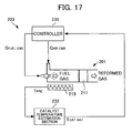
- FIG. 17 is a schematic diagram showing a configuration of a control apparatus 203 of a fuel reformer 201 of a second technique.
- the control apparatus 203 is configured to include a catalyst temperature estimation section 232 that sets a temperature T PRE of a heater 215 that heats the reforming catalyst 211 of the fuel reformer 201 as an input and calculates an estimated temperature T CAT HAT of the reforming catalyst 211 based on a predetermined catalyst thermal model, and a controller 230 that calculates an optimum supply amount G AIR CMD of air and supply amount G FUEL CMD of fuel to supply to the reforming catalyst 211 based on the estimated temperature T CAT HAT of this catalyst temperature estimation section 232, and outputs these command values G AIR CMD and G FUEL CMD to the fuel reformer 201.
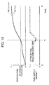
- FIGS. 18 and 19 are time charts that respectively show examples of control of a fuel reformer by the second technique. More specifically, FIG. 18 shows an example of control in a state prior to the reforming catalyst degrading, and FIG. 19 shows an example of control in a state after the reforming catalyst has degraded.
- the solid lines 18a and 19a indicate time change of the actual temperature T CAT of the reforming catalyst
- the point-dashed lines 18b and 19b indicate an estimated temperature T CAT HAT of catalyst temperature estimation.
- the estimated temperature T CAT HAT of the catalyst temperature estimation section matches the actual temperature T CAT of the reforming catalyst. This enables starting of the injection of fuel at the optimum fuel injection time t 3 .
- Patent Document 1 a control apparatus is exemplified that detects degradation of the catalyst by estimating the temperature of the catalyst based on a thermal model, similarly to the aforementioned first technique, and comparing the detected temperature of a temperature sensor that detects the temperature of the catalyst with this estimated temperature.
- the estimated temperature of the catalyst is corrected in response to the detected temperature of the temperature sensor based on the thermal model. This makes temperature control that takes degradation of the catalyst into account possible.
- a control apparatus that estimates a temperature of a catalyst based on a thermal model, and adjusts a parameter related to control of an engine such as ignition timing and a target air/fuel ratio, based on this estimated temperature.
- a model coefficient of the thermal model is corrected based on deviation between the estimated temperature of the catalyst that is based on the thermal model and the detected temperature of the temperature sensor detecting the temperature of the catalyst. This makes temperature control that takes degradation of the catalyst into account possible.
- US 5,857,163 A and US 5,544,639 A each disclose a control apparatus that controls the temperature of a catalyst for treating internal combustion engine exhaust gases comprising: temperature sensors for detecting the catalyst temperature; temperature' prediction means for estimating the catalyst temperature based on an accurate temperature model associated to several parameters which take into account the catalyst deterioration; temperature control means and correction means for correcting the correlation model used to estimate the catalyst temperature.
- JP 2002-121002 A discloses a control apparatus for a fuel reformer comprising temperature detection means, temperature estimation means, temperature estimation means, temperature control means and temperature correction means.
- the thermal model is corrected by a successive least-squares method that can only correct a constant contained in a linear model.
- the exothermic characteristic of the reforming reaction and the like are described by a non-linear function. Therefore, with the control apparatus of Patent Document 2, the catalyst after degradation cannot be reproduced with sufficient precision.
- the control apparatus of Patent Document 2 when the temperature of the catalyst changes suddenly such as during rapid warm-up control execution immediately after start up or during regeneration control execution of the catalyst, the emitted amount of unreacted hydrocarbons may increase, fuel economy may deteriorate, and the temperature of the reforming catalyst may rise excessively and degrade.
- the present invention has been made taking the aforementioned points into account, and has an object of providing a control method of a fuel reformer that can control taking into account the non-linearity of the thermal model of the reforming reaction. model of the reforming reaction.
- a control apparatus for performing the method includes: a temperature detection means (21) for detecting, the catalyst temperature; a temperature estimation means (32) for estimating, with parameters characterizing a reforming reaction of the reforming catalyst set as a first parameter (T CAT , T CAT HAT ) and a second parameter (C CAT ), respectively, the catalyst temperature based on a correlation model associating the first parameter and the second parameter; a temperature control means (30) for controlling a temperature of the reforming catalyst based on an estimated temperature (T CAT HAT ) of the temperature estimation means; and a model correction means (34) for defining a plurality of correction weighting functions (W 0 , W 1 , W 2 , W 3 , W 4 ) that set the first parameter to a domain of definition, calculating a plurality of local
- the catalyst temperature is estimated based on the correlation model, which relates to the first parameter and second parameter characterizing the reforming reaction and associates these parameters, and the temperature of the reforming catalyst is controlled based on this estimated temperature.
- the correlation model which relates to the first parameter and second parameter characterizing the reforming reaction and associates these parameters
- the temperature of the reforming catalyst is controlled based on this estimated temperature.
- a model correction means that defines the plurality of correction weighting functions that set the first parameter to a domain of definition, calculates a plurality of local correction coefficients that are multiplied by this correction weighting function, and correct the correlation model based on the plurality of correction weighting functions and local correction coefficients.
- the first parameter is the catalyst temperature (T CAT , T CAT HAT ), and the second parameter is a catalytic reaction thermal coefficient (C CAT ) that indicates a heat generation state of a reforming reaction of the reforming catalyst.
- the first parameter is set to be the catalyst temperature
- the second parameter is set to be the catalytic reaction thermal coefficient.
- control apparatus further includes a detected value estimation means (341) for estimating an output value of the temperature detection means in accordance with an estimated temperature (T CAT HAT ) of the temperature estimation means, based on a model of the temperature detection means.
- the model correction means calculates the plurality of local correction coefficients so that deviation (em) between the detected temperature (T CAT SNS ) of the temperature detection means and the estimated temperature (T CSNS HAT ) of the detected value estimation means converges.
- the output value of this catalyst temperature means is estimated, and the local correction coefficient is calculated so that the deviation between this estimated temperature and the detected temperature of the catalyst temperature means converges.
- the deviation between this estimated temperature and detected temperature causes degradation of the reforming catalyst. It is possible to suitably correct the correlation model to match the degradation of the reforming catalyst by calculating the local correction coefficients so that this deviation converges.
- the model correction means calculates the plurality of local correction coefficients based on response specifying control.
- the plurality of local correction coefficients is calculated based on response specifying control. For example, in a case of calculating such a plurality of local correction coefficients simultaneously, there is mutual interference, and cyclically oscillating behavior may be expressed and may diverge. However, by calculating the plurality of local correction coefficients based on response specifying control, it can be calculated stably without inducing such interference.
- the plurality of correction weighting functions is each a function that changes within the change region, and is set so as to intersect each other within the change region.
- a region in which the second parameter changes is set as a change region, and the plurality of correction weighting functions changes within this change region, and is set so as to intersection with each other within this change region.
- the correlation mode can be precisely corrected without requiring an excessive operational load.
- the temperature detection means detects a catalyst temperature of a portion of the reforming catalyst at which the reforming reaction temperature is the highest, and the temperature control means controls the temperature of the reforming catalyst so that the estimated temperature of the temperature estimation means is lower than a predetermined deactivation temperature (T CAT H ) of the reforming catalyst.
- T CAT H a predetermined deactivation temperature
- the catalyst temperature of a portion in the reforming catalyst at which the reforming reaction temperature is the highest is detected by the temperature detection means, and the temperature of the reforming catalyst is controlled so that the estimated temperature of the reforming catalyst is lower than a predetermined deactivation temperature. This enables degradation, resulting from the reforming catalyst exceeding the deactivation temperature, to be prevented.
- the fuel reformer is equipped in a vehicle provided with an internal combustion engine, and the reforming reaction of the reforming catalyst is an exothermic reaction.
- the temperature of the reforming catalyst can be controlled with higher precision. That is, inside the bonnet, the temperature change is small due to not being greatly influenced by wind and rain. As a result, the estimation accuracy of the temperature of the reforming catalyst can be further improved.
- the temperature control means controls the temperature of the reforming catalyst by sliding mode control based on a predetermined conversion function setting parameter (V POLE ) ⁇
- the temperature of the reforming catalyst is controlled by sliding mode control based on a predetermined conversion function setting parameter. This enables control to be performed so that the temperature of the reforming catalyst is brought close within a predetermined range, and thus the fuel reformer to be operated stably, for example.
- the conversion function setting parameter is set within a range of -1 to 0 to a value closer to -1 than 0, in a case in which an operating state of the fuel reformer is in a steady state.
- the conversion function setting parameter is set within the range of -1 to 0 to a value closer to -1 than 0. In particular, this enables excessive consumption of fuel to be suppressed when temperatures rise, and enables overshoot of the temperature of the reforming catalyst to be suppressed.
- FIG. 1 is a schematic diagram showing a configuration of a fuel reformer 1 and an electronic control unit (hereinafter referred to as "ECU") 3 as a control method thereof relating to an embodiment of the present invention.
- ECU electronice control unit
- the fuel reformer 1 is configured to include a gas channel 12 of a cylindrical shape in which a reforming catalyst 11 is provided inside thereof, and an air supply device 13 and fuel supply device 14 that supply air and fuel from an end side of this gas channel 12.
- this fuel reformer 1 is of straight-flow type in which the flow of gas on an inlet side of the reforming catalyst 11 and a flow of gas on an outlet side of the reforming catalyst 11 are the same direction.
- the air supply device 13 is configured by a compressor, valve, and the like, which are not illustrated, and supplies air into the gas channel 12 in accordance with a control signal (G AIR CMD ) output from the ECU 3.
- the fuel supply device 14 is configured by a fuel tank, valve, injector, and the like, which are not illustrated, and supplies fuel into the gas channel 12 in accordance with a control signal (G FUEL CMD ) output from the ECU 3.
- G FUEL CMD control signal
- the air and fuel supplied by the air supply device 13 and the fuel supply device 14 are mixed inside the gas channel 12, and are supplied to the reforming catalyst 11 as fuel gas.
- the reforming catalyst 11 reforms the fuel gas supplied from the air supply device 13 and the fuel supply device 14, and produces reformed gas containing hydrogen, carbon monoxide, and hydrocarbons. More specifically, this reforming catalyst 11 produces reformed gas by way of a partial oxidation reaction of the hydrocarbon fuel and air constituting the fuel gas, i.e. an exothermal reaction.
- the reforming catalyst 11 a catalyst prepared by weighing powder of ceria and rhodium so as to make the mass ratio of rhodium to ceria 1%, producing a slurry by placing this powder in a ball mill along with an aqueous medium and agitating and mixing, and then after coating this slurry on a support made of Fe-Cr-Al alloy, drying and calcining this over 2 hours at 600°C.
- a heater 15 which preheats the reforming catalyst 11 with fuel gas inside the gas channel 12 and promotes activity of the reforming catalyst 11, is provided in the fuel reformer 1.
- a catalyst temperature sensor 21 as a temperature detection means that detects the temperature of the reforming catalyst 11 and outputs the temperature thus detected to the ECU 3 as a detected temperature T CAT SNS , and a heater temperature sensor (not illustrated) that detects the temperature of the heater 15 and outputs the temperature thus detected to the ECU 3 as a detected temperature T PRE are provided in the fuel reformer 1.
- the catalyst temperature sensor 21 is preferably provided in the fuel reformer 1 so as to detect the temperature of the portion having the highest temperature in the reforming catalyst 11.
- the fuel reformer 1 configured as described above is, for example, equipped in a vehicle, which is not illustrated, provided with an internal combustion engine.
- the reformed gas produced by the fuel reformer 1 is preferably introduced to the exhaust system of the internal combustion engine, which is provided with a catalyst and filter that purify the exhaust.
- the ECU 3 is provided with an input circuit having functions of shaping input signal waveforms from various sensors, correcting the voltage levels to predetermined levels, converting analogy signal values to digital signal values, etc., and a central processing unit (hereinafter referred to as "CPU").
- CPU central processing unit
- the ECU 3 is provided with a memory circuit that stores various operational programs executed by the CPU, maps and tables referred to by this program, calculation results of programs, etc., and an output circuit that outputs control signals to the fuel reformer 1.
- FIG. 1 only shows the functional blocks in the aforementioned ECU 3 that relate to control of the fuel reformer 1. More specifically, the functional blocks of the ECU 3 are configured to include a controller 30 as a catalyst temperature control means for controlling the fuel reformer 1, a catalyst temperature estimation section 32 as a catalyst temperature estimation means for estimating the temperature of the reforming catalyst 11, a model correction section 34 as a model correction means, and a parameter setting section 36 that sets various parameters.
- a controller 30 as a catalyst temperature control means for controlling the fuel reformer 1
- a catalyst temperature estimation section 32 as a catalyst temperature estimation means for estimating the temperature of the reforming catalyst 11
- a model correction section 34 as a model correction means
- a parameter setting section 36 that sets various parameters.
- the catalyst temperature estimation section 32 estimates the temperature of the reforming catalyst 11 based on a temperature differential equation described in detail later, and outputs the temperature thus estimated to the controller 30 and model correction section 34 as an estimated temperature T CAT HAT ⁇
- the model correction section 34 corrects the correlation model included in the temperature differential equation of the catalyst temperature estimation section 32 based on the detected temperature T CAT SNS and the estimated temperature T CAT HAT .
- the controller 30 controls the temperature of the reforming catalyst by calculating the air supply amount G AIR CMD and fuel supply amount G FUEL CMD of the fuel reformer 1 based on sliding mode control, which is described later in detail, so that the deviation between the estimated temperature T CAT HAT output from the catalyst temperature estimation section 32 and the target temperature T CAT TARGET of the fuel reformer output from the parameter setting section converges, and outputting this air supply amount G AIR CMD and fuel supply amount G FUEL CMD thus calculated to the fuel reformer 1.
- the parameter setting section 36 sets a target temperature T CAT TARGET of the reforming catalyst 11 and a hydrogen production amount (load of fuel reformer) G CYL from the reforming catalyst 11 according to operating conditions of the fuel reformer 1, and outputs this target temperature T CAT TARGET and hydrogen production amount G CYL to the controller 30 and catalyst temperature estimation section 32.
- controller 30 The configuration of the controller 30 will be explained in detail while referring to FIGS. 2 to 5 .
- FIG. 2 is a block diagram showing the configuration of the controller 30.
- the controller 30 is configured to include a sliding mode controller 31 that calculates a control input U SL so that the estimated temperature T CAT HAT converges to the target temperature T CAT TARGET , and a fuel supply amount map 311, air supply amount map 312, and correction amount map 315 for calculating the fuel supply amount G FUEL CMD and air supply amount G AIR CMD based on the hydrogen production amount G CYL and the control input U SL .
- sliding mode control is a further development of so-called response specifying control that can specify a convergence rate of a control amount, and is control that can separately specify the pursuit rate to the target value of the control amount and the convergence rate of the control amount in the case of noise being applied.
- the reforming catalyst of the fuel reformer described above is used at a high temperature when producing reformed gas, and is limited also to this temperature range. For example, due to deactivation resulting in a case of this temperature range having been exceeded, overshoot of the temperature of the reforming catalyst is preferably avoided if at all possible. In addition, in a case of falling below the temperature range, the rate of the reforming reaction may decline and come to be an impediment to autonomous operation. Consequently, by performing such sliding mode control, it becomes possible to control the temperature of the reforming catalyst within a predetermined temperature range without causing overshoot.
- the symbol (k) is a symbol indicating discretized time, and indicates being data detected or calculated in each predetermined control period. Specifically, in a case in which the symbol (k) has been set to be data detected or calculated at the present control timing, the symbol (k-1) indicates being data detected or calculated at a previous control timing.
- the deviation between the estimated temperature T CAT HAT (k) of the reforming catalyst and the target temperature T CAT TARGET (k) of the reforming catalyst is calculated by an adder 301, and this is defined as a temperature deviation amount e(k).
- e k T CAT HAT k - T CAT TARGET k
- V POLE is searched by a V POLE setting section 302 according to an estimated temperature T CAT HAT , and the product of the V POLE thus found and a temperature deviation amount e(k-1) of a previous control time calculated by a delay computing unit 303 is calculated.
- V POLE is a conversion function setting parameter that is set to a value larger than -1 and smaller than 0, and is set based on a V POLE table described later with reference to FIG. 5 .
- the sum of the temperature deviation amount e(k) and the product V POLE x e(k-1) is calculated by an adder 305, and this is defined as a conversion function ⁇ (k).
- ⁇ k e k + V POLE ⁇ e ⁇ k - 1
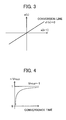
- FIG. 3 is a graph showing a phase plane with the horizontal axis as the temperature deviation amount e(k-1) at a previous control time, and the vertical axis defined as the temperature deviation amount e(k) at a present control time.
- FIG. 4 is a graph showing a relationship between the conversion function setting parameter V POLE and the convergence time of the temperature deviation amount. More specifically, the horizontal axis indicates the convergence time to the target value of the temperature deviation amount and the vertical axis indicates a slope (-V POLE ) of the conversion line. As shown in FIG. 4 , the convergence time becomes longer as -V POLE approaches 1 from 0.
- FIG. 5 is a graph showing a configuration of a V POLE table stored in the V POLE setting section 302 described above. More specifically, the horizontal axis shows the estimated temperature T CAT HAT , and the vertical axis shows the conversion function setting parameter V POLE .
- a maximum temperature T CAT H and a minimum temperature T CAT L are a maximum temperature and a minimum temperature of the reforming catalyst that are set in advance in order to perform the reforming reaction efficiently, respectively. More specifically, the maximum temperature T CAT H is a deactivation temperature, i.e. a temperature at which the reforming catalyst may deactivate and degrade if it exceeds this temperature.
- the minimum temperature T CAT L is a temperature at which the rate of the reforming reaction may decline if the reforming catalyst drops below this temperature. Therefore, for the temperature of the reforming catalyst, it is preferable to steadily operate within the range from this minimum temperature T CAT L up to maximum temperature T CAT H . Then, the target temperature T CAT TARGET of the reforming catalyst is normally set between the minimum temperature T CAT L and maximum temperature T CAT H .
- V POLE is set to a value larger than -1 and less than 0.
- the conversion function setting parameter V POLE is set based on the estimated temperature T CAT HAT , as shown in the following formulas (6-1), (6-2), and (6-3).
- the temperature of the reforming catalyst is made to gently converge with the target temperature T CAT TARGET , and in a case of the estimated temperature T CAT HAT not being between the minimum temperature T CAT L and the maximum temperature T CAT H , the temperature of the reforming catalyst can be made to quickly converge with the target temperature T CAT TARGET .
- the temperature of the reforming catalyst is controlled so as to drift between the minimum temperature T CAT L and the maximum temperature T CAT H .
- a reaching-law input U RCH (k) and an adaptive-law input U ADP (k) are calculated based on the conversion function ⁇ (k) calculated as described above, and further, the sum of this reaching-law input U RCH (k) and adaptive-law input U ADP (k) is calculated by the adder 309, as shown in the following formula (7), and this is defined as a control input U SL (k).
- U SL k U RCH k + U ADP k
- the reaching-law input U RCH (k) is an input for placing the temperature deviation amount onto the conversion line, and is calculated with an amplifier 306 by multiplying the conversion function ⁇ (k) by a reaching-law control gain K RCH , as shown in the following formula (8).
- U RCH k K RCH ⁇ ⁇ k
- the adaptive-law input U ADP (k) suppresses the influences of modeling error and noise, is an input for placing the temperature deviation amount on the conversion line, and is calculated by calculating an integral of the conversion function ⁇ (k) with an integrator 307, and multiplying this value of the integral by the reaching-law control gain K ADP .
- AT is a control period.
- this reaching-law control gain K RCH and adaptive-law control gain K ADP are set to optimum values based on experimentation, so that the temperature deviation amount is stably placed on the conversion line, under the policy of temperature control of the reforming catalyst described above.
- the fuel supply amount map 311 and the air supply amount map 312 respectively calculate the map values G FUEL MAP and G AIR MAP of the fuel supply amount and the air supply amount according to the hydrogen production amount G CYL , based on a predetermined control map for supply amount determination.
- the correction amount map 315 calculates the correction amounts G FUEL FB and G AIR FB of the fuel supply amount and air supply amount according to the control input U SL of the sliding mode controller 31, based on a predetermined control map for correction amount determination.
- the temperature of the reforming catalyst can be made to increase by increasing the air supply amount or reducing the fuel supply amount.
- the hydrogen production amount may decline by reducing the fuel supply amount, it is preferred to cause the temperature of the reforming catalyst to increase by increasing the air supply amount.
- the temperature of the reforming catalyst can be made to decline by reducing the air supply amount or increasing the fuel supply amount.
- the emitted amount of unburned fuel may increase by increasing the fuel supply amount, it is preferred to cause the temperature of the reforming catalyst to decline by reducing the air supply amount.
- control map for correction amount determination is set to match the control map for supply amount determination described above.
- a fuel correction amount G FUEL FB and air correction amount G AIR FB calculated as described above are added to the fuel supply amount map value G FUEL MAP and the air supply amount map value G AIR MAP , respectively, by the adders 313 and 314, these values thus added are defined as the fuel supply amount G FUEL CMD and air supply amount G AIR CMD , and output to the fuel reformer.
- the catalyst temperature estimation section 32 calculates the estimated temperature T CAT HAT (k) of the reforming catalyst 11, based on the temperature difference equation as shown in the following formula (10).
- T CAT HAT k - T CAT HAT ⁇ k - 1 ⁇ T + A CAT T CAT HAT ⁇ k - 1 - T A ⁇ k - 1 + B CAT ⁇ G CYL ⁇ k - 1 L CAT ⁇ G CYL MAX T PRE ⁇ k - 1 - T CAT HAT ⁇ k - 1 + C CAT ⁇ k - 1 ⁇ K C ⁇ k - 1 ⁇ G CYL ⁇ k - 1
- the first term on the right side is an advective term, and is a term showing a contribution by the migration of heat between the reforming catalyst 11 and the atmosphere.
- the second term on the right is a heat-transfer term, and is a term showing a contribution by migration of heat between the reforming catalyst 11 and the heater 15.
- the third term on the right is a heat generation term, and is a term showing a contribution of heat generated by the reforming reaction of the reforming catalyst 11.
- the heat generation term is a term influenced by the exothermic reaction of the reforming catalyst 11, and changes with degradation of the reforming catalyst 11.
- C CAT indicates a catalytic reaction thermal coefficient, and is calculated based on a correlation model shown in FIG. 6 described later.
- K C indicates a correction coefficient of the catalytic reaction thermal coefficient C CAT , and is calculated by the model correction section 34.
- L CAT is a length along a layering direction of the reforming catalyst, and adopts a value set in advance.
- T A is ambient temperature, and adopts a detected temperature of an ambient temperature sensor, which is not illustrated.
- G CYL MAX is the maximum hydrogen production amount of the fuel reformer 1, and adopts a value set in advance.
- a CAT and B CAT are parameters of the advective term and heat-transfer term, respectively, and are set to optimal values based on experimentation.
- these parameters A CAT and B CAT are set based on the reforming catalyst prior to degradation, they are not limited thereto.
- these parameters and constants may be set based on a catalyst that has been used for a predetermined time and has been degraded.
- FIG. 6 is a graph showing a configuration of a correlation model between the temperature T CAT of the reforming catalyst as a first parameter, and the catalyst reaction thermal coefficient C CAT as a second parameter.
- the catalytic reaction thermal coefficient C CAT is a coefficient indicating the heat generation state of the reforming reaction of the reforming catalyst, and is expressed as a non-linear function of the catalyst temperature T CAT .
- the correlation between this catalytic reaction thermal coefficient C CAT and catalyst temperature T CAT change with degradation of the reforming catalyst. More specifically, the solid line 6a indicates the correlation between the catalytic reaction thermal coefficient C CAT and catalyst temperature T CAT of the reforming catalyst prior to degradation, and the dotted line 6b indicates the correlation between the catalytic reaction thermal coefficient C CAT and catalyst temperature T CAT of the reforming catalyst after degradation. In this way, variation in the properties consequent upon degradation of the catalytic reaction thermal coefficient C CAT is not at a fixed rate, and also becomes non-linear.
- the catalytic reaction thermal coefficient C CAT is a value close to 0.
- the catalytic reaction thermal coefficient C CAT also increases with a rise in the catalyst temperature T CAT from when the catalyst temperature T CAT exceeds the first temperature TL until reaching a predetermined second temperature T H .
- the catalytic reaction thermal coefficient C CAT for the reforming catalyst prior to degradation increases quickly with a rise in the catalyst temperature T CAT compared to the reforming catalyst after degradation.
- the catalytic reaction thermal coefficient C CAT becomes substantially constant at a predetermined upper limit value, irrespective of the catalyst temperature T CAT .
- the catalyst temperature estimation section 32 calculates the catalytic reaction thermal coefficient C CAT according to the estimated temperature T CAT HAT based on such a correlation model of the reforming catalyst.
- the first parameter was set as the catalyst temperature T CAT of the reforming catalyst 11 in the aforementioned explanation, the catalytic reaction thermal coefficient C CAT is calculated in actual control, due to the catalyst temperature T CAT being replaced with the estimated temperature T CAT HAT .
- the catalytic reaction thermal coefficient C CAT is calculated based on the correlation model of the reforming catalyst prior to degradation shown by the solid line 6a.
- the correlation model of the reforming catalyst after degradation as shown by the dotted line 6b is reproduced by multiplying the correction coefficient K C calculated by the model correction section 34 described later by the catalytic reaction thermal coefficient C CAT .
- the catalyst temperature estimation section 32 calculates the catalytic reaction thermal coefficient C CAT according to the estimated temperature T CAT HAT based on the aforementioned correlation model, and further estimates the temperature of the reforming catalyst 11 by the temperature difference equation shown in formula (10). Specifically, the estimated temperature T CAT HAT is calculated by the following formula (11) derived by rearranging the aforementioned formula (10).
- T CAT HAT k 1 + A CAT ⁇ ⁇ T - B CAT ⁇ G CYL ⁇ k - 1 ⁇ ⁇ T L CAT ⁇ G CYL MAX ⁇ T CAT HAT ⁇ k - 1 + B CAT ⁇ G CYL ⁇ k - 1 ⁇ ⁇ T L CAT ⁇ G CYL MAX ⁇ T PRE ⁇ k - 1 - A CAT ⁇ T A ⁇ k - 1 ⁇ ⁇ T + C CAT ⁇ k - 1 ⁇ K C ⁇ k - 1 ⁇ G CYL ⁇ k - 1 ⁇ ⁇ T
- the model correction section 34 is configured to include a temperature sensor model 341 as a detection value estimation means for estimating an output value of the catalyst temperature sensor 21, and a correction coefficient calculation section 342 that calculates a correction coefficient K C of the correlation model of the catalyst temperature estimation section 32, based on a correction algorithm described later.
- the temperature sensor model 341 estimates a detected temperature of the catalyst temperature sensor 21 according to the estimated temperature T CAT HAT output from the catalyst temperature estimation section 32, based on a sensor model reproducing the output of the catalyst temperature sensor 21. More specifically, the temperature sensor model 341 calculates an output estimated temperature T CSNS HAT based on a sensor model shown in the following formula (12), which takes into account the response lag of the catalyst temperature sensor 21.
- T CSNS HAT k - K S ⁇ T CSNS HAT ⁇ k - 1 + 1 + K S ⁇ T CAT HAT k
- K S indicates a sensor lag coefficient, and is set to an optimal value in the range of -1 ⁇ K S ⁇ 0 by experimentation and system identification.
- the correction coefficient calculation section 342 calculates a correction coefficient K C such that the deviation between the detected temperature T CAT SNS output from the catalyst temperature sensor 21 and the output estimated temperature T CSNS HAT output from the temperature sensor model 341 converges. In other words, this correction coefficient calculation section 342 calculates the correction coefficient K C by way of setting the deviation between the detected temperature T CAT SNS and the output estimated temperature T CSNS HAT to be a matter mainly causing degradation of the reforming catalyst.
- the catalytic reaction thermal coefficient C CAT shows a non-linear characteristic relative to the catalyst temperature T CAT , as well as showing a non-linear characteristic relatively to the progression of degradation. Therefore, when calculating the correction coefficient K C , in a case of having applied a control algorithm of successive least-squares method, fixed gain method, or the like, which are conventionally known, it is difficult to reproduce the non-linear characteristic of the catalytic reaction thermal coefficient C CAT due to only a constant in the model being able to be identified.
- neural network control which learns characteristics of tables and maps, is known conventionally as a method of reproducing non-linearity, it is difficult to put to practical use in temperature control of a fuel reformer due to this method lacking stability.
- FIG. 7 is a graph showing a configuration of the correction weighting functions W 0 to W 4 .
- the correction weighting functions W i are coefficients for which the temperature T CAT (estimated temperature T CAT HAT ) of the reforming catalyst is set to a domain of definition and 0 to 1 is set as the range of values, respectively.
- these correction weighting functions W i are set to a region of temperature in which the catalytic reaction thermal coefficient C CAT changes, i.e. a region of change from the first temperature T L to the second temperature T H , and in this region of change, are set so as to intersect each other, while values thereof change between this region of change. More specifically, the temperatures T 1 , T 2 , and T 3 within this region of change are set at substantially equal intervals, and each of the correction weighting functions W i is set as follows due to the region of change being divided into four regions from this.
- the correction weighting function W 0 is 1 from a temperature of 0 to T L , decreases from 1 to 0 from T L to T 1 , and is 0 at T 1 and higher.
- the correction weighting function W 1 is 0 from a temperature of 0 to T L , rises from 0 to 1 from T L to T 1 , decreases from 1 to 0 from T 1 to T 2 , and is 0 at T 2 and higher.
- the correction weighting function W 2 is 0 from a temperature of 0 to T 1 , rises from 0 to 1 from T 1 to T 2 , decreases from 1 to 0 from T 2 to T 3 , and is 0 at T 3 and higher.
- the correction weighting function W 3 is 0 from a temperature of 0 to T 2 , rises from 0 to 1 from T 2 to T 3 , decreases from 1 to 0 from T 4 to T H , and is 0 at T H and higher.
- the correction weighting function W 4 is 0 from a temperature of 0 to T 3 , rises from 0 to 1 from T 3 to T H , and is 1 at T H and higher.
- FIG. 8 is a block diagram showing a configuration of the correction coefficient calculation section 342.
- the deviation between the detected temperature T CAT SNS output from the catalyst temperature sensor and the output estimated temperature T CSNS HAT output from the temperature sensor model is calculated by the adder 343, and this is defined as a sensor temperature deviation amount em(k).
- em k T CAT SNS ⁇ k - 1 - T CSNS HAT ⁇ k - 1
- the correction weighting functions W 0 , W 1 , W 2 , W 3 , and W 4 are calculated according to the estimated temperature T CAT HAT , based on the correction weighting function maps 344a, 344b, 344c, 344d, and 344e.
- the product of each of the correction weighting functions W 0 to W 4 and the sensor temperature deviation amount em(k) are calculated by the multipliers 345a, 345b, 345c, 345d, and 345e, and this is defined as weighted errors ew 0 , ew 1 , ew 2 , ew 3 , and ew 4 .
- ew i k W i k ⁇ em k
- controllers 346a, 346b, 346c, 346d, and 346e calculate the local correction coefficients K CL 0 to K CL 4 as shown in the following formulas (15) to (19) by way of response specifying control, i.e. sliding mode control based on predetermined conversion function setting parameters.
- K CL NLi is an input for restraining the weighted error ew i on the conversion line.
- K CL RCHi is an input for placing the weighted error ew i on the conversion line.
- K CL ADPi is an input for suppressing the influence of modeling errors and noise, and restraining the weighted error ew i on the conversion line.
- K NL L is a non-linear input control gain
- K RCH L is a reaching law control gain
- K ADP L is an adaptive law control gain, and each is set to an optimum value based on experimentation so that the weighted error ew i appears stably on the conversion line.
- ⁇ Li is a conversion function relating to the weighted error ew i .
- S1 is a conversion function setting parameter, and is set to a value larger than -1 and smaller than 0.
- the products of the local correction coefficients K CL 0 to K CL 4 and the local correction coefficients W 0 to W 4 are calculated by way multipliers 347a, 347b, 347c, 347d, and 347e and an adder 348, and the correction coefficient K C is calculated by summing these products.
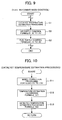
- FIG. 9 is a flowchart showing a sequence of main control of the fuel reformer by the ECU. It should be noted that, in this flowchart, only a sequence relating to temperature control of the fuel reformer is shown, and sequences for warm up control, shut down control of the fuel reformer, and the like are omitted. In addition, each step is executed in a control cycle of 5 msec, for example.
- Step 1 In the main control of the fuel reformer, first catalyst temperature estimation processing, which is described in detail with reference to FIG. 10 later, is executed in Step 1, and then Step S2 is advanced to.
- Step S2 air supply control is executed.
- the air supply amount G AIR CMD is calculated based on the above formulas (4) to (9), and is then output to the air supply device of the fuel reformer.
- Step S3 fuel supply control is executed.
- the fuel supply amount G FUEL CMD is calculated based on the above formulas (4) to (9), and is then output to the fuel supply device of the fuel reformer.
- FIG. 1 is a flowchart showing a sequence of catalyst temperature estimation processing.
- Step S11 model correction processing is executed.
- the correction coefficient K C of the catalytic reaction thermal coefficient C CAT of the reforming catalyst is calculated based on the above formulas (13) to (19).
- Step S12 temperature estimation processing is executed.
- the estimated temperature T CAT HAT of the reforming catalyst is calculated based on the above formula (11).
- Step S13 detected temperature estimation processing is executed.
- the output estimated temperature T CSNS of the catalyst temperature sensor is calculated based on the above formula (12).
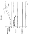
- FIGS. 11 and 12 are time charts showing time change of the temperature T CAT of the reforming catalyst and the conversion function setting parameter V POLE of a comparative example and the present embodiment.
- the comparative example of the present embodiment shows control using the detected temperature T CAT SNS of the catalyst temperature sensor 21 in place of the estimated temperature T CAT HAT of the catalyst temperature estimation section 32 as an input of the controller 30 (refer to FIG. 1 ).
- a time chart of the comparative example will be explained with reference to FIG. 11 .
- control is performed to quickly bring the temperature of the reforming catalyst close to the target temperature T CAT TARGET by setting the conversion function setting parameter V POLE to a value close to 0.
- control is performed to gently bring the temperature of the reforming catalyst close to T CAT TARGET by setting the conversion function setting parameter V POLE to a value close to -1, in response to the detected temperature T CAT SNS having exceeded the minimum temperature T L .
- control is performed to quickly bring the temperature of the reforming catalyst close to the target temperature T CAT TARGET again, by setting the conversion function setting parameter V POLE to a value close to 0.
- the detected temperature T CAT SNS of the temperature sensor has a delay compared to the actually catalyst temperature T CAT .
- the actual catalyst temperature T CAT may be higher than the maximum temperature T H and overshoot, and thus the reforming catalyst may degrade.
- a time chart of the present embodiment will be explained while referring to FIG. 12 .
- control is performed to quickly bring the temperature of the reforming catalyst close to the target temperature T CAT TARGET by setting the conversion function setting parameter V POLE to a value close to 0.
- control is performed to gently bring the temperature of the reforming catalyst close to T CAT TARGET by setting the conversion function setting parameter V POLE to a value close to -1, in response to the estimated temperature T CAT HAT having exceeded the minimum temperature T L .
- control is performed to quickly bring the temperature of the reforming catalyst close to the target temperature T CAT TARGET again, by setting the conversion function setting parameter V POLE to a value close to 0.
- the actual catalyst temperature T CAT begins to converge to the target temperature T CAT TARGET once more, without overshooting the maximum temperature T H , as shown in FIG. 11 .
- the present embodiment it is possible to control the temperature of the reforming catalyst to between the minimum temperature T L and maximum temperature T H by controlling the fuel reformer based on the estimated temperature T CAT HAT , which does not have a delay relative to the actual catalyst temperature T CAT .
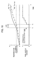
- FIGS. 13 and 14 are time charts showing time change of the temperature T CAT of the reforming catalyst, the fuel supply amount G FUEL CMD , and the correction coefficient K C prior to degradation and after degradation of the reforming catalyst, respectively.
- an estimated temperature T CAT HAT close to the actually catalyst temperature T CAT can be calculated without correcting the correlation model, i.e. without changing the correction coefficient K C from 1. This enables the supply of fuel to be started at the optimal fuel start time t 9 .
- an estimated temperature T CAT HAT close to the actual catalyst temperature T CAT can be calculated by changing the correction coefficient K C from 1 and correcting the correlation model. This enables the supply of fuel to be started at the optimal fuel start time t 10 .
- the catalyst temperature is estimated based on the correlation model, which relates to the temperature of the reforming catalyst 11 and the catalytic reaction thermal coefficient C CAT characterizing the reforming reaction and associates these parameters, and the temperature of the reforming catalyst 11 is controlled based on this estimated temperature T CAT HAT .
- the temperature of the reforming catalyst 11 is controlled based on this estimated temperature T CAT HAT .
- the temperature of the reforming catalyst 11 may deactivate in a case of overshoot having occurred due to use in a high temperature region close to the heat-resistance limit, it is preferred to avoid overshoot of the temperature as much as possible.
- a model correction section 34 is provided that defines the plurality of correction weighting functions W i that set the temperature of the reforming catalyst to a domain of definition, calculates a plurality of local correction coefficients K CL i that are multiplied by this correction weighting function based on the estimated temperature T CAT HAT of the reforming catalyst, and corrects the correlation model based on the plurality of correction weighting functions W i and local correction coefficients K CL i .
- the first parameter is set to be the catalyst temperature T CAT
- the second parameter is set to be the catalytic reaction thermal coefficient C CAT .
- the output value of this catalyst temperature sensor 21 is estimated, and the local correction coefficient K CL i is calculated so that the deviation em between this estimated temperature T CSNS HAT and the detected temperature T CAT SNS of the catalyst temperature sensor 21 converges.
- the deviation em between this estimated temperature T CSNS HAT and detected temperature T CAT SNS causes degradation of the reforming catalyst. It is possible to suitably correct the correlation model to match the degradation of the reforming catalyst by calculating the local correction coefficients K CL i so that this deviation em converges.
- the plurality of local correction coefficients K CL i is calculated based on response specifying control. For example, in a case of calculating such a plurality of local correction coefficients K CL i simultaneously, there is mutual interference, and cyclically oscillating behavior may be expressed and may diverge. However, by calculating the plurality of local correction coefficients K CL i based on response specifying control, it can be calculated stably without inducing such interference.
- a region in which the catalytic reaction thermal coefficient C CAT changes is set as a change region, and the plurality of correction weighting functions W i change within this change region, and is set so as to intersection with each other within this change region.
- the correlation mode can be precisely corrected without requiring excessive operational load.
- the catalyst temperature of a portion in the reforming catalyst 11 at which the reforming reaction temperature is the highest is detected by the catalyst temperature sensor 21, and the temperature of the reforming catalyst 11 is controlled so that the estimated temperature T CAT HAT of the reforming catalyst 11 is lower than a predetermined deactivation temperature T H .
- This enables degradation, resulting from the reforming catalyst 11 exceeding the deactivation temperature T H , to be prevented.
- the temperature of the reforming catalyst 11 can be controlled with higher precision. That is, inside the bonnet, the temperature change is small due to not being greatly influenced by wind and rain. As a result, the estimating precision of the temperature of the reforming catalyst 11 can be further improved.
- the temperature of the reforming catalyst 11 is controlled by sliding mode control based on the predetermined conversion function setting parameter V POLE . This enables control to be performed so that the temperature of the reforming catalyst 11 is brought close within a predetermined range, and thus enables the fuel reformer 1 to be operated stably, for example.
- the conversion function setting parameter V POLE is set within a range from -1 to 0 to a value closer to -1 than 0. This enables the consumption of excess fuel during warming up to be curbed, in particular, and enables overshoot of the temperature of the reforming catalyst to be suppressed.
- the ECU 3 configures a temperature estimation means, temperature control means, model correction means, and detected value estimation means. More specifically, the catalyst temperature estimation section 32 of FIG. 1 corresponds to the temperature estimation means, the controller 30 corresponds to the temperature control means, the model correction section 34 corresponds to the model correction means, and the temperature sensor model 341 corresponds to the detected value estimation means.
- the estimated temperature T CAT HAT of the reforming catalyst was calculated using the detected temperature T PRE of this temperature sensor; it is not limited thereto.
- the estimated temperature T CAT HAT of the reforming catalyst may be calculated using a temperature T PRE HAT estimated by way of a map, instead of the detected temperature T PRE of the temperature sensor of the heater.
- the correlation model was defined with the first parameter as the temperature T CAT of the reforming catalyst and the second parameter as the catalytic reaction thermal coefficient C CAT , it is not limited thereto.
- the correlation model may be defined using an amount related to the exothermic reaction of the reforming catalyst such as the hydrogen production amount of the reforming catalyst or the inlet temperature of the reforming catalyst, as the second parameter.
- the local correction coefficients K CL 0 to K CL 4 were calculated based on sliding mode control in the controllers 346a to 346e, it is not limited thereto.
- the local correction coefficients K CL 0 to K CL 4 may be calculated based on a method that is conventionally known such as PID control, optimization control, backstepping control, and H-infinity control.
- sliding mode control and backstepping control which can prevent interference of each of the local correction coefficients K CL 0 to K CL 4 by causing the weighted error ew i to exponentially converge, are preferred.
Applications Claiming Priority (2)
| Application Number | Priority Date | Filing Date | Title |
|---|---|---|---|
| JP2008031573A JP5015025B2 (ja) | 2008-02-13 | 2008-02-13 | 燃料改質器の制御装置 |
| PCT/JP2008/070698 WO2009101736A1 (ja) | 2008-02-13 | 2008-11-13 | 燃料改質器の制御装置 |
Publications (3)
| Publication Number | Publication Date |
|---|---|
| EP2246294A1 EP2246294A1 (en) | 2010-11-03 |
| EP2246294A4 EP2246294A4 (en) | 2011-03-23 |
| EP2246294B1 true EP2246294B1 (en) | 2014-09-03 |
Family
ID=40956774
Family Applications (1)
| Application Number | Title | Priority Date | Filing Date |
|---|---|---|---|
| EP08872309.3A Not-in-force EP2246294B1 (en) | 2008-02-13 | 2008-11-13 | Control method for fuel reformer |
Country Status (4)
| Country | Link |
|---|---|
| US (1) | US20100324749A1 (ja) |
| EP (1) | EP2246294B1 (ja) |
| JP (1) | JP5015025B2 (ja) |
| WO (1) | WO2009101736A1 (ja) |
Families Citing this family (13)
| Publication number | Priority date | Publication date | Assignee | Title |
|---|---|---|---|---|
| JP5149647B2 (ja) | 2008-02-20 | 2013-02-20 | 本田技研工業株式会社 | 燃料改質装置 |
| KR101091627B1 (ko) * | 2009-08-31 | 2011-12-08 | 기아자동차주식회사 | 배기 시스템 |
| JP5006947B2 (ja) | 2010-01-14 | 2012-08-22 | 本田技研工業株式会社 | プラントの制御装置 |
| JP5561655B2 (ja) * | 2010-09-30 | 2014-07-30 | Toto株式会社 | 固体酸化物形燃料電池装置 |
| US8903624B2 (en) * | 2011-02-24 | 2014-12-02 | Toyota Jidosha Kabushiki Kaisha | Internal combustion engine control apparatus |
| JP5653834B2 (ja) * | 2011-05-13 | 2015-01-14 | 本田技研工業株式会社 | 燃料電池システム |
| JP5675490B2 (ja) | 2011-05-13 | 2015-02-25 | 本田技研工業株式会社 | 燃料電池モジュール |
| FR2976020A1 (fr) * | 2011-05-31 | 2012-12-07 | Renault Sa | Dispositif de reformage, systeme de traitement des gaz d'echappement comprenant un tel dispositif et procede correspondant |
| JP2016130185A (ja) * | 2015-01-13 | 2016-07-21 | 株式会社デンソー | 燃料改質装置 |
| EP3309121A1 (en) * | 2016-10-14 | 2018-04-18 | Air Products And Chemicals, Inc. | Monitoring the activity of reforming catalyst |
| US9945801B1 (en) | 2016-10-14 | 2018-04-17 | Air Products And Chemicals, Inc. | Monitoring the activity of reforming catalyst |
| DE102018204456A1 (de) * | 2017-11-24 | 2019-05-29 | Fraunhofer-Gesellschaft zur Förderung der angewandten Forschung e.V. | Verfahren zum Betrieb eines katalytischen Verdampfers und Anwendungen des Verfahrens |
| AT520522B1 (de) * | 2017-12-05 | 2019-05-15 | Avl List Gmbh | Regelung einer Regelgröße einer Konditioniereinheit eines Reaktanden einer Brennstoffzelle mit Ermittlung eines Istwertes der Regelgröße |
Citations (2)
| Publication number | Priority date | Publication date | Assignee | Title |
|---|---|---|---|---|
| JP2002121002A (ja) * | 2000-10-12 | 2002-04-23 | Nissan Motor Co Ltd | 燃料改質装置 |
| EP1676991A2 (en) * | 2004-12-28 | 2006-07-05 | HONDA MOTOR CO., Ltd. | Plant temperature control system |
Family Cites Families (6)
| Publication number | Priority date | Publication date | Assignee | Title |
|---|---|---|---|---|
| US5544639A (en) * | 1993-08-31 | 1996-08-13 | Nippondenso Co., Ltd. | Temperature predicting system for internal combustion engine and temperature control system including same |
| US5857163A (en) * | 1995-12-12 | 1999-01-05 | General Motors Corporation | Adaptive engine control responsive to catalyst deterioration estimation |
| DE19726791A1 (de) * | 1997-06-24 | 1999-01-07 | Volkswagen Ag | Verfahren zur Überwachung der Konvertierungsrate eines Abgaskatalysators für eine Brennkraftmaschine |
| WO2002070873A1 (fr) * | 2001-03-02 | 2002-09-12 | Hitachi, Ltd. | Dispositif et procede permettant de realiser le diagnostic d'un moteur a combustion interne et procede de commande d'un moteur a combustion interne utilisant lesdits dispositif et procede |
| JP3849480B2 (ja) * | 2001-10-01 | 2006-11-22 | 日産自動車株式会社 | 燃料改質器の制御装置 |
| JP4039304B2 (ja) * | 2003-04-18 | 2008-01-30 | トヨタ自動車株式会社 | 改質触媒劣化判定装置、燃料改質装置および改質触媒劣化判定方法 |
-
2008
- 2008-02-13 JP JP2008031573A patent/JP5015025B2/ja not_active Expired - Fee Related
- 2008-11-13 US US12/867,048 patent/US20100324749A1/en not_active Abandoned
- 2008-11-13 EP EP08872309.3A patent/EP2246294B1/en not_active Not-in-force
- 2008-11-13 WO PCT/JP2008/070698 patent/WO2009101736A1/ja active Application Filing
Patent Citations (2)
| Publication number | Priority date | Publication date | Assignee | Title |
|---|---|---|---|---|
| JP2002121002A (ja) * | 2000-10-12 | 2002-04-23 | Nissan Motor Co Ltd | 燃料改質装置 |
| EP1676991A2 (en) * | 2004-12-28 | 2006-07-05 | HONDA MOTOR CO., Ltd. | Plant temperature control system |
Also Published As
| Publication number | Publication date |
|---|---|
| JP5015025B2 (ja) | 2012-08-29 |
| EP2246294A4 (en) | 2011-03-23 |
| US20100324749A1 (en) | 2010-12-23 |
| WO2009101736A1 (ja) | 2009-08-20 |
| JP2009190913A (ja) | 2009-08-27 |
| EP2246294A1 (en) | 2010-11-03 |
Similar Documents
| Publication | Publication Date | Title |
|---|---|---|
| EP2246294B1 (en) | Control method for fuel reformer | |
| JP4767218B2 (ja) | 内燃機関の排ガス浄化装置 | |
| JP5149988B2 (ja) | プラントの制御装置 | |
| US8578705B2 (en) | Control of selective catalytic reduction | |
| US20120310507A1 (en) | Method and device for controlling an scr catalytic converter of a vehicle | |
| EP2400124B1 (en) | Exhaust gas purification system for internal combustion engine | |
| US20090246569A1 (en) | Method for regenerating a reformer | |
| EP1261054B1 (en) | Combustor temperature control of a fuel cell power plant | |
| JP3674441B2 (ja) | 改質器制御装置 | |
| CN112664342B (zh) | 一种三元催化剂控制方法及系统 | |
| CN115680844A (zh) | 用于确定废气催化器的转化能力的方法、计算单元和计算机程序 | |
| US20170167341A1 (en) | System and method for emission control in power plants | |
| US8448504B2 (en) | Exhaust catalyst temperature estimating apparatus and exhaust catalyst temperature estimation method for internal combustion engine | |
| JP2011069296A (ja) | 脱硝触媒の劣化予測方法、劣化対策方法、劣化対策システム及び排ガス処理システムの設計方法 | |
| KR102270963B1 (ko) | 내연기관을 작동하기 위한 방법 및 제어장치 | |
| JP4816164B2 (ja) | 排気ガスの推定装置 | |
| CN114592947A (zh) | 用于内燃机的尿素喷射控制系统 | |
| JP2011144055A (ja) | 燃料改質装置 | |
| JP2006132355A (ja) | 内燃機関及び内燃機関の運転制御装置 | |
| JP2021113537A (ja) | 尿素scrシステム | |
| JP3882550B2 (ja) | 移動体用燃料改質システムの制御装置 | |
| CN111798936B (zh) | 一种scr催化器储nh3量的计算方法 | |
| JPH10311212A (ja) | 内燃機関の排気浄化装置 | |
| JP4888415B2 (ja) | 燃料電池用改質装置の運転制御方法 | |
| Yasui | Robust identification algorithms for adaptive engine controls |
Legal Events
| Date | Code | Title | Description |
|---|---|---|---|
| PUAI | Public reference made under article 153(3) epc to a published international application that has entered the european phase |
Free format text: ORIGINAL CODE: 0009012 |
|
| 17P | Request for examination filed |
Effective date: 20100810 |
|
| AK | Designated contracting states |
Kind code of ref document: A1 Designated state(s): AT BE BG CH CY CZ DE DK EE ES FI FR GB GR HR HU IE IS IT LI LT LU LV MC MT NL NO PL PT RO SE SI SK TR |
|
| AX | Request for extension of the european patent |
Extension state: AL BA MK RS |
|
| A4 | Supplementary search report drawn up and despatched |
Effective date: 20110221 |
|
| DAX | Request for extension of the european patent (deleted) | ||
| 17Q | First examination report despatched |
Effective date: 20120210 |
|
| RIC1 | Information provided on ipc code assigned before grant |
Ipc: C01B 3/38 20060101AFI20140224BHEP Ipc: F02D 41/14 20060101ALI20140224BHEP Ipc: F02D 19/06 20060101ALI20140224BHEP Ipc: F02D 41/00 20060101ALI20140224BHEP Ipc: F01N 9/00 20060101ALI20140224BHEP Ipc: H01M 8/06 20060101ALI20140224BHEP Ipc: F01N 3/035 20060101ALI20140224BHEP |
|
| GRAP | Despatch of communication of intention to grant a patent |
Free format text: ORIGINAL CODE: EPIDOSNIGR1 |
|
| INTG | Intention to grant announced |
Effective date: 20140417 |
|
| GRAS | Grant fee paid |
Free format text: ORIGINAL CODE: EPIDOSNIGR3 |
|
| GRAA | (expected) grant |
Free format text: ORIGINAL CODE: 0009210 |
|
| AK | Designated contracting states |
Kind code of ref document: B1 Designated state(s): AT BE BG CH CY CZ DE DK EE ES FI FR GB GR HR HU IE IS IT LI LT LU LV MC MT NL NO PL PT RO SE SI SK TR |
|
| REG | Reference to a national code |
Ref country code: GB Ref legal event code: FG4D |
|
| REG | Reference to a national code |
Ref country code: AT Ref legal event code: REF Ref document number: 685476 Country of ref document: AT Kind code of ref document: T Effective date: 20140915 Ref country code: CH Ref legal event code: EP |
|
| REG | Reference to a national code |
Ref country code: IE Ref legal event code: FG4D |
|
| REG | Reference to a national code |
Ref country code: DE Ref legal event code: R096 Ref document number: 602008034281 Country of ref document: DE Effective date: 20141016 |
|
| REG | Reference to a national code |
Ref country code: AT Ref legal event code: MK05 Ref document number: 685476 Country of ref document: AT Kind code of ref document: T Effective date: 20140903 |
|
| PG25 | Lapsed in a contracting state [announced via postgrant information from national office to epo] |
Ref country code: ES Free format text: LAPSE BECAUSE OF FAILURE TO SUBMIT A TRANSLATION OF THE DESCRIPTION OR TO PAY THE FEE WITHIN THE PRESCRIBED TIME-LIMIT Effective date: 20140903 Ref country code: FI Free format text: LAPSE BECAUSE OF FAILURE TO SUBMIT A TRANSLATION OF THE DESCRIPTION OR TO PAY THE FEE WITHIN THE PRESCRIBED TIME-LIMIT Effective date: 20140903 Ref country code: GR Free format text: LAPSE BECAUSE OF FAILURE TO SUBMIT A TRANSLATION OF THE DESCRIPTION OR TO PAY THE FEE WITHIN THE PRESCRIBED TIME-LIMIT Effective date: 20141204 Ref country code: NO Free format text: LAPSE BECAUSE OF FAILURE TO SUBMIT A TRANSLATION OF THE DESCRIPTION OR TO PAY THE FEE WITHIN THE PRESCRIBED TIME-LIMIT Effective date: 20141203 Ref country code: SE Free format text: LAPSE BECAUSE OF FAILURE TO SUBMIT A TRANSLATION OF THE DESCRIPTION OR TO PAY THE FEE WITHIN THE PRESCRIBED TIME-LIMIT Effective date: 20140903 Ref country code: LT Free format text: LAPSE BECAUSE OF FAILURE TO SUBMIT A TRANSLATION OF THE DESCRIPTION OR TO PAY THE FEE WITHIN THE PRESCRIBED TIME-LIMIT Effective date: 20140903 |
|
| PGFP | Annual fee paid to national office [announced via postgrant information from national office to epo] |
Ref country code: DE Payment date: 20140915 Year of fee payment: 7 |
|
| REG | Reference to a national code |
Ref country code: NL Ref legal event code: VDEP Effective date: 20140903 |
|
| REG | Reference to a national code |
Ref country code: LT Ref legal event code: MG4D |
|
| PG25 | Lapsed in a contracting state [announced via postgrant information from national office to epo] |
Ref country code: AT Free format text: LAPSE BECAUSE OF FAILURE TO SUBMIT A TRANSLATION OF THE DESCRIPTION OR TO PAY THE FEE WITHIN THE PRESCRIBED TIME-LIMIT Effective date: 20140903 Ref country code: CY Free format text: LAPSE BECAUSE OF FAILURE TO SUBMIT A TRANSLATION OF THE DESCRIPTION OR TO PAY THE FEE WITHIN THE PRESCRIBED TIME-LIMIT Effective date: 20140903 Ref country code: HR Free format text: LAPSE BECAUSE OF FAILURE TO SUBMIT A TRANSLATION OF THE DESCRIPTION OR TO PAY THE FEE WITHIN THE PRESCRIBED TIME-LIMIT Effective date: 20140903 Ref country code: LV Free format text: LAPSE BECAUSE OF FAILURE TO SUBMIT A TRANSLATION OF THE DESCRIPTION OR TO PAY THE FEE WITHIN THE PRESCRIBED TIME-LIMIT Effective date: 20140903 |
|
| PG25 | Lapsed in a contracting state [announced via postgrant information from national office to epo] |
Ref country code: NL Free format text: LAPSE BECAUSE OF FAILURE TO SUBMIT A TRANSLATION OF THE DESCRIPTION OR TO PAY THE FEE WITHIN THE PRESCRIBED TIME-LIMIT Effective date: 20140903 |
|
| PG25 | Lapsed in a contracting state [announced via postgrant information from national office to epo] |
Ref country code: CZ Free format text: LAPSE BECAUSE OF FAILURE TO SUBMIT A TRANSLATION OF THE DESCRIPTION OR TO PAY THE FEE WITHIN THE PRESCRIBED TIME-LIMIT Effective date: 20140903 Ref country code: SK Free format text: LAPSE BECAUSE OF FAILURE TO SUBMIT A TRANSLATION OF THE DESCRIPTION OR TO PAY THE FEE WITHIN THE PRESCRIBED TIME-LIMIT Effective date: 20140903 Ref country code: RO Free format text: LAPSE BECAUSE OF FAILURE TO SUBMIT A TRANSLATION OF THE DESCRIPTION OR TO PAY THE FEE WITHIN THE PRESCRIBED TIME-LIMIT Effective date: 20140903 Ref country code: IS Free format text: LAPSE BECAUSE OF FAILURE TO SUBMIT A TRANSLATION OF THE DESCRIPTION OR TO PAY THE FEE WITHIN THE PRESCRIBED TIME-LIMIT Effective date: 20150103 Ref country code: PT Free format text: LAPSE BECAUSE OF FAILURE TO SUBMIT A TRANSLATION OF THE DESCRIPTION OR TO PAY THE FEE WITHIN THE PRESCRIBED TIME-LIMIT Effective date: 20150105 Ref country code: EE Free format text: LAPSE BECAUSE OF FAILURE TO SUBMIT A TRANSLATION OF THE DESCRIPTION OR TO PAY THE FEE WITHIN THE PRESCRIBED TIME-LIMIT Effective date: 20140903 |
|
| PG25 | Lapsed in a contracting state [announced via postgrant information from national office to epo] |
Ref country code: PL Free format text: LAPSE BECAUSE OF FAILURE TO SUBMIT A TRANSLATION OF THE DESCRIPTION OR TO PAY THE FEE WITHIN THE PRESCRIBED TIME-LIMIT Effective date: 20140903 |
|
| REG | Reference to a national code |
Ref country code: DE Ref legal event code: R097 Ref document number: 602008034281 Country of ref document: DE |
|
| PG25 | Lapsed in a contracting state [announced via postgrant information from national office to epo] |
Ref country code: LU Free format text: LAPSE BECAUSE OF FAILURE TO SUBMIT A TRANSLATION OF THE DESCRIPTION OR TO PAY THE FEE WITHIN THE PRESCRIBED TIME-LIMIT Effective date: 20141113 Ref country code: BE Free format text: LAPSE BECAUSE OF NON-PAYMENT OF DUE FEES Effective date: 20141130 Ref country code: MC Free format text: LAPSE BECAUSE OF FAILURE TO SUBMIT A TRANSLATION OF THE DESCRIPTION OR TO PAY THE FEE WITHIN THE PRESCRIBED TIME-LIMIT Effective date: 20140903 |
|
| REG | Reference to a national code |
Ref country code: CH Ref legal event code: PL |
|
| PLBE | No opposition filed within time limit |
Free format text: ORIGINAL CODE: 0009261 |
|
| STAA | Information on the status of an ep patent application or granted ep patent |
Free format text: STATUS: NO OPPOSITION FILED WITHIN TIME LIMIT |
|
| PG25 | Lapsed in a contracting state [announced via postgrant information from national office to epo] |
Ref country code: DK Free format text: LAPSE BECAUSE OF FAILURE TO SUBMIT A TRANSLATION OF THE DESCRIPTION OR TO PAY THE FEE WITHIN THE PRESCRIBED TIME-LIMIT Effective date: 20140903 Ref country code: CH Free format text: LAPSE BECAUSE OF NON-PAYMENT OF DUE FEES Effective date: 20141130 Ref country code: LI Free format text: LAPSE BECAUSE OF NON-PAYMENT OF DUE FEES Effective date: 20141130 |
|
| 26N | No opposition filed |
Effective date: 20150604 |
|
| GBPC | Gb: european patent ceased through non-payment of renewal fee |
Effective date: 20141203 |
|
| REG | Reference to a national code |
Ref country code: IE Ref legal event code: MM4A |
|
| REG | Reference to a national code |
Ref country code: FR Ref legal event code: ST Effective date: 20150731 |
|
| PG25 | Lapsed in a contracting state [announced via postgrant information from national office to epo] |
Ref country code: IT Free format text: LAPSE BECAUSE OF FAILURE TO SUBMIT A TRANSLATION OF THE DESCRIPTION OR TO PAY THE FEE WITHIN THE PRESCRIBED TIME-LIMIT Effective date: 20140903 |
|
| PG25 | Lapsed in a contracting state [announced via postgrant information from national office to epo] |
Ref country code: GB Free format text: LAPSE BECAUSE OF NON-PAYMENT OF DUE FEES Effective date: 20141203 Ref country code: IE Free format text: LAPSE BECAUSE OF NON-PAYMENT OF DUE FEES Effective date: 20141113 |
|
| PG25 | Lapsed in a contracting state [announced via postgrant information from national office to epo] |
Ref country code: SI Free format text: LAPSE BECAUSE OF FAILURE TO SUBMIT A TRANSLATION OF THE DESCRIPTION OR TO PAY THE FEE WITHIN THE PRESCRIBED TIME-LIMIT Effective date: 20140903 Ref country code: FR Free format text: LAPSE BECAUSE OF NON-PAYMENT OF DUE FEES Effective date: 20141201 |
|
| PG25 | Lapsed in a contracting state [announced via postgrant information from national office to epo] |
Ref country code: BG Free format text: LAPSE BECAUSE OF FAILURE TO SUBMIT A TRANSLATION OF THE DESCRIPTION OR TO PAY THE FEE WITHIN THE PRESCRIBED TIME-LIMIT Effective date: 20140903 |
|
| REG | Reference to a national code |
Ref country code: DE Ref legal event code: R119 Ref document number: 602008034281 Country of ref document: DE |
|
| PG25 | Lapsed in a contracting state [announced via postgrant information from national office to epo] |
Ref country code: BE Free format text: LAPSE BECAUSE OF FAILURE TO SUBMIT A TRANSLATION OF THE DESCRIPTION OR TO PAY THE FEE WITHIN THE PRESCRIBED TIME-LIMIT Effective date: 20140903 Ref country code: HU Free format text: LAPSE BECAUSE OF FAILURE TO SUBMIT A TRANSLATION OF THE DESCRIPTION OR TO PAY THE FEE WITHIN THE PRESCRIBED TIME-LIMIT; INVALID AB INITIO Effective date: 20081113 Ref country code: TR Free format text: LAPSE BECAUSE OF FAILURE TO SUBMIT A TRANSLATION OF THE DESCRIPTION OR TO PAY THE FEE WITHIN THE PRESCRIBED TIME-LIMIT Effective date: 20140903 Ref country code: MT Free format text: LAPSE BECAUSE OF FAILURE TO SUBMIT A TRANSLATION OF THE DESCRIPTION OR TO PAY THE FEE WITHIN THE PRESCRIBED TIME-LIMIT Effective date: 20140903 |
|
| PG25 | Lapsed in a contracting state [announced via postgrant information from national office to epo] |
Ref country code: DE Free format text: LAPSE BECAUSE OF NON-PAYMENT OF DUE FEES Effective date: 20160601 |