EP2245348B1 - Rückschlagventil und kolbenpumpe mit rückschlagventil - Google Patents
Rückschlagventil und kolbenpumpe mit rückschlagventil Download PDFInfo
- Publication number
- EP2245348B1 EP2245348B1 EP20090704179 EP09704179A EP2245348B1 EP 2245348 B1 EP2245348 B1 EP 2245348B1 EP 20090704179 EP20090704179 EP 20090704179 EP 09704179 A EP09704179 A EP 09704179A EP 2245348 B1 EP2245348 B1 EP 2245348B1
- Authority
- EP
- European Patent Office
- Prior art keywords
- valve
- check valve
- pressure
- housing
- piston
- Prior art date
- Legal status (The legal status is an assumption and is not a legal conclusion. Google has not performed a legal analysis and makes no representation as to the accuracy of the status listed.)
- Active
Links
Images


Classifications
-
- F—MECHANICAL ENGINEERING; LIGHTING; HEATING; WEAPONS; BLASTING
- F16—ENGINEERING ELEMENTS AND UNITS; GENERAL MEASURES FOR PRODUCING AND MAINTAINING EFFECTIVE FUNCTIONING OF MACHINES OR INSTALLATIONS; THERMAL INSULATION IN GENERAL
- F16K—VALVES; TAPS; COCKS; ACTUATING-FLOATS; DEVICES FOR VENTING OR AERATING
- F16K15/00—Check valves
- F16K15/02—Check valves with guided rigid valve members
- F16K15/03—Check valves with guided rigid valve members with a hinged closure member or with a pivoted closure member
- F16K15/031—Check valves with guided rigid valve members with a hinged closure member or with a pivoted closure member the hinge being flexible
-
- F—MECHANICAL ENGINEERING; LIGHTING; HEATING; WEAPONS; BLASTING
- F04—POSITIVE - DISPLACEMENT MACHINES FOR LIQUIDS; PUMPS FOR LIQUIDS OR ELASTIC FLUIDS
- F04B—POSITIVE-DISPLACEMENT MACHINES FOR LIQUIDS; PUMPS
- F04B1/00—Multi-cylinder machines or pumps characterised by number or arrangement of cylinders
- F04B1/04—Multi-cylinder machines or pumps characterised by number or arrangement of cylinders having cylinders in star- or fan-arrangement
- F04B1/0404—Details or component parts
- F04B1/0452—Distribution members, e.g. valves
-
- F—MECHANICAL ENGINEERING; LIGHTING; HEATING; WEAPONS; BLASTING
- F04—POSITIVE - DISPLACEMENT MACHINES FOR LIQUIDS; PUMPS FOR LIQUIDS OR ELASTIC FLUIDS
- F04B—POSITIVE-DISPLACEMENT MACHINES FOR LIQUIDS; PUMPS
- F04B53/00—Component parts, details or accessories not provided for in, or of interest apart from, groups F04B1/00 - F04B23/00 or F04B39/00 - F04B47/00
- F04B53/10—Valves; Arrangement of valves
- F04B53/1037—Flap valves
- F04B53/1047—Flap valves the valve being formed by one or more flexible elements
- F04B53/1052—Flap valves the valve being formed by one or more flexible elements two flexible elements oscillating around a fixed point
-
- F—MECHANICAL ENGINEERING; LIGHTING; HEATING; WEAPONS; BLASTING
- F16—ENGINEERING ELEMENTS AND UNITS; GENERAL MEASURES FOR PRODUCING AND MAINTAINING EFFECTIVE FUNCTIONING OF MACHINES OR INSTALLATIONS; THERMAL INSULATION IN GENERAL
- F16K—VALVES; TAPS; COCKS; ACTUATING-FLOATS; DEVICES FOR VENTING OR AERATING
- F16K15/00—Check valves
- F16K15/02—Check valves with guided rigid valve members
- F16K15/03—Check valves with guided rigid valve members with a hinged closure member or with a pivoted closure member
- F16K15/035—Check valves with guided rigid valve members with a hinged closure member or with a pivoted closure member with a plurality of valve members
- F16K15/036—Dual valve members with hinges crossing the flow line substantially diametrical
- F16K15/038—Dual valve members with hinges crossing the flow line substantially diametrical having a common hinge
-
- F—MECHANICAL ENGINEERING; LIGHTING; HEATING; WEAPONS; BLASTING
- F16—ENGINEERING ELEMENTS AND UNITS; GENERAL MEASURES FOR PRODUCING AND MAINTAINING EFFECTIVE FUNCTIONING OF MACHINES OR INSTALLATIONS; THERMAL INSULATION IN GENERAL
- F16K—VALVES; TAPS; COCKS; ACTUATING-FLOATS; DEVICES FOR VENTING OR AERATING
- F16K15/00—Check valves
- F16K15/14—Check valves with flexible valve members
-
- F—MECHANICAL ENGINEERING; LIGHTING; HEATING; WEAPONS; BLASTING
- F01—MACHINES OR ENGINES IN GENERAL; ENGINE PLANTS IN GENERAL; STEAM ENGINES
- F01N—GAS-FLOW SILENCERS OR EXHAUST APPARATUS FOR MACHINES OR ENGINES IN GENERAL; GAS-FLOW SILENCERS OR EXHAUST APPARATUS FOR INTERNAL-COMBUSTION ENGINES
- F01N2610/00—Adding substances to exhaust gases
- F01N2610/02—Adding substances to exhaust gases the substance being ammonia or urea
-
- F—MECHANICAL ENGINEERING; LIGHTING; HEATING; WEAPONS; BLASTING
- F01—MACHINES OR ENGINES IN GENERAL; ENGINE PLANTS IN GENERAL; STEAM ENGINES
- F01N—GAS-FLOW SILENCERS OR EXHAUST APPARATUS FOR MACHINES OR ENGINES IN GENERAL; GAS-FLOW SILENCERS OR EXHAUST APPARATUS FOR INTERNAL-COMBUSTION ENGINES
- F01N2610/00—Adding substances to exhaust gases
- F01N2610/14—Arrangements for the supply of substances, e.g. conduits
- F01N2610/1433—Pumps
-
- Y—GENERAL TAGGING OF NEW TECHNOLOGICAL DEVELOPMENTS; GENERAL TAGGING OF CROSS-SECTIONAL TECHNOLOGIES SPANNING OVER SEVERAL SECTIONS OF THE IPC; TECHNICAL SUBJECTS COVERED BY FORMER USPC CROSS-REFERENCE ART COLLECTIONS [XRACs] AND DIGESTS
- Y10—TECHNICAL SUBJECTS COVERED BY FORMER USPC
- Y10T—TECHNICAL SUBJECTS COVERED BY FORMER US CLASSIFICATION
- Y10T137/00—Fluid handling
- Y10T137/7722—Line condition change responsive valves
- Y10T137/7837—Direct response valves [i.e., check valve type]
Definitions
- the present invention relates to a check valve for the arrangement between a first pressure chamber, in which a first pressure of a fluid prevails, and a second pressure chamber, in which a second pressure prevails, with a valve housing, on which a valve seat is formed, and with a blocking element, which is designed in a blocking position to close a valve opening in the region of the valve seat in order to block a connection between the first and the second valve chamber, when the second pressure is greater than the first pressure, and is designed in an open position, the Release valve opening to release the connection between the first and the second valve chamber, when the first pressure is greater than the second pressure, wherein the fluid in the opening position along a flow direction from the first pressure chamber into the second pressure chamber can flow, wherein the valve seat as Inclined surface is formed in relation to the flow direction is at an angle greater than 15 ° and less than 80 °, wherein the blocking element has a flat locking tab made of an elastically deformable material which abuts in the locking position on the inclined surface and in the open position due
- the present invention further relates to a fluid pump with a pump housing and a displaceably mounted therein piston, which forms a pressure chamber with the pump housing, wherein a suction port of the pump via a first check valve is connected to the pressure chamber and wherein the pressure chamber via a second check valve with a pressure port the pump is connected.
- check valve is well known.
- a check valve is generally used to determine the direction of the flow of a fluid and is a directional control valve, which automatically blocks the passage of the fluid in one of the two flow directions.
- the valve seat form as an inclined surface, the fluid in the open position unhindered or flow favorable flow into the second pressure chamber.
- the fluid pushes off the planar locking tab from the valve seat and can flow along the deflecting flap deflected into the second pressure chamber without the fluid being greatly deflected with respect to the flow direction, as is the case, for example, with classical valves Check valves is the case.
- a check valve for a filler pipe of a fuel tank of a motor vehicle is known.
- the check valve has a housing and movably mounted, by the inflowing fuel opening and automatically re-closing valve flaps.
- a holder is provided for fixing the two valve flaps on the housing. The holder in turn is latched via corresponding locking elements on the housing.
- ball check valves in which the blocking element is formed by a ball which is pressed by a spring in the valve seat.
- valve seat is arranged perpendicular to the flow direction and closed by a flap.
- the flap can in particular be suspended at an upper area, so that it automatically enters the blocking position due to its own weight.
- Piston pumps are pumps for conveying fluids, wherein the fluid to be delivered is sucked through an inlet valve with the piston in a first cycle. It is then expelled through the outlet valve in a second cycle.
- a pump can also be referred to as a positive displacement pump.
- the blocking element has a fastening portion, by means of which the blocking element is attached to the valve housing, wherein the attachment portion has a ring portion which is inserted into an annular mounting recess of the valve housing.
- the check valve according to the invention has an oblique valve seat against which a locking tab made of elastically deformable material.
- the blocking element can be fixed without further measures in the radial direction of the valve housing. This may be particularly advantageous when the valve is arranged on a movable element such as a piston.
- the check valve according to the invention comes out with few components.
- the valve consists only of the valve housing and the blocking element.
- the valve port may include a plurality of individual ports, which are collectively closed by a blocking element.
- the valve openings are arranged to each other so that they are aligned the same in the radial direction, so that the fluid from the individual openings at the same "height" impinges on the locking tab.
- the locking tab Due to the formation of the locking tab of an elastically deformable material can be achieved that the locking tab is biased due to its own elasticity in the locked position. As a result, the lock position can also be achieved generally safely.
- the function of the check valve according to the invention is similar to the function of fish gills, which are also optimized aerodynamically due to evolution. Even with comparatively high operating frequencies of the check valve, this results in no flutter.
- the check valve according to the invention is suitable for comparatively high actuation limits, for example for actuation frequencies of up to 60 or 70 Hz.
- the angle of the inclined surface is greater than 30 °.
- valve can be further optimized in terms of flow.
- the angle of the inclined surface is smaller than 60 °.
- the blocking element is fixed to a rear region, viewed in the flow direction, of the inclined surface on the valve housing.
- valve seat has two inclined surfaces which are inclined in the opposite direction and form a V-shape in longitudinal section, wherein each inclined surface is associated with a locking tab.
- the valve thus includes two parallel check valves. In this way, the radial forces occurring can be compensated against each other. Therefore, this training is preferably also when the check valve is part of a movable system in the flow direction, for example, is arranged on a piston.
- the number of components can be kept low.
- the valve housing has a mounting recess, which is aligned transversely to the flow direction, wherein the mounting portion is inserted into the mounting recess to fix the locking element in the flow direction in a form-fitting manner to the valve housing.
- the attachment of the blocking element to the valve housing without additional components or materials can be done. It is conceivable here that the blocking element has a bead running transversely to the flow direction, which is inserted into a corresponding transverse recess of the valve housing in order to achieve an axially positive connection.
- the ring section is connected to the locking tab via at least one longitudinal web section.
- the longitudinal web section is arranged in a longitudinally aligned recess of the valve housing.
- attachment portion of the locking element can be integrated, for example, in a cylinder contour of the valve housing, without the attachment portion projecting in the radial direction outwards relative to the cylinder contour.
- this embodiment is therefore suitable for the use of the check valve on a movable element.
- two locking tabs are connected to each other at a transverse web (for example in V-shape), whose ends are each connected via a longitudinal web portion with the ring portion.
- This embodiment enables an axially stable connection between the locking tab and the ring portion.
- valve housing has a cylinder section which has at least one longitudinal passage connected to the valve opening, wherein the valve seat is formed on an end face of the cylinder section, seen in particular in the flow direction forward.
- This embodiment allows for a simple housing structure.
- the second pressure chamber can be formed for example by the cylinder portion and a second housing portion.
- the longitudinal channel then preferably forms part of the first pressure chamber.
- the check valve can be integrated in a simple manner into a cylindrical piston, specifically on its end face.
- the above object is also achieved by the above-mentioned fluid pump, wherein the suction port is connected to a compensation chamber into which fluid passes, which emerges between the piston and the pump housing, and wherein the first and / or the second and or the third check valve is designed as a check valve according to the present invention.
- the fluid pump according to the invention is particularly suitable for those fluids which tend to crystallize or agglomerate at standstill.
- the fluid pump according to the invention is consequently suitable as a urea pump, for example for a urea injection system for the exhaust gas purification of diesel engines.
- check valve according to the invention comes out with few components.
- a piston rod of the piston is guided out of the pump housing in the region of the compensation chamber through a piston rod opening.
- the compensation chamber can in this case be arranged in particular concentrically to the piston rod, so that results in a simple construction.
- the sealing arrangement has a membrane section.
- Such a membrane section can be designed to be elastic on a regular basis and, on account of this elasticity, can assist the pump action of the pump or generate its own pumping action. Because the sealing arrangement is entrained in axial movements of the piston, so that this can result in changes in volume of the compensation chamber.
- this pumping action can be achieved in a particularly advantageous manner when the diaphragm section extends in the radial direction between an outer circumference of the piston and an inner circumference of the compensation chamber. This also allows a simple construction of the flexible sealing arrangement.
- the flexible sealing arrangement has a bellows section which extends around the piston rod.
- Such a bellows section can also absorb the axial movements of the piston, in the axial direction.
- the sealing of the sealing arrangement relative to the piston rod opening due to the axial alignment can be realized structurally simple.
- a bellows section is preferred when the fluid is not or only slightly compressible, such as a liquid (especially urea).
- a liquid especially urea
- the bellows section has a neutral cylinder contour whose circumference corresponds to the outer circumference of the piston section which extends into the compensation space.
- the piston is sealed off from the pump housing by means of an annular sealing element which has an axial annular recess open towards the pressure side, via which the fluid under pressure can press an annular sealing lip inward in the radial direction.
- the sealing effect between the piston and the pump housing can be increased structurally simple. Furthermore, can be achieved by this measure, that a radially inner wear of the sealing lip (which may rest radially inwardly on the movable piston) over the life of the fluid pump is compensated.
- the pump housing has a main housing on which the piston is displaceably mounted, a pressure-side cover and a suction-side cover, wherein the covers are connected at axially opposite ends to the main housing.
- the pump housing structurally simple and compact realize.
- the axially opposite cover next to the training the pressure chamber on the one hand and the compensation chamber on the other hand assume other functions.
- the second check valve can be pre-assembled in this way on the pressure-side cover, there is a simple installation.
- the main housing has an axial recess which is closed by means of the suction-side cover.
- the axial recess can be used in this way for the realization of various functions, as described below.
- the axial recess includes the compensation chamber.
- the compensation space can be realized structurally simple.
- Such a ring insert can also fulfill various functions, in particular sealing tasks at axially opposite ends of the axial recess.
- the ring insert defines an annular sealing element for sealing the piston relative to the pump housing in the axial direction against a bottom of the axial recess.
- annular sealing element can be structurally easily mounted and fixed in the pump housing.
- the ring insert is fixed by means of the suction-side cover in the axial recess.
- a sealing arrangement is defined between the ring insert and the suction-side cover.
- the sealing arrangement may be part of the flexible sealing arrangement, which is provided for sealing the piston with respect to the piston rod opening, wherein the piston rod opening is preferably formed in the suction-side cover in this case.
- the first check valve is fixed to the piston.
- the check valve may preferably be arranged on an end face of the piston. This may be a suction-side end face, but it is preferably the pressure-side end face.
- a third check valve is arranged in the region of the suction connection.
- a further advantageous embodiment of the fluid pump includes connecting the piston rod opening with a consumer for pressurized gas.
- This air may be supplied to a consumer for pressurized gases, e.g. Air are supplied.
- the piston rod opening is connected to a gas guide channel which surrounds at least one section of the piston rod protruding from the pump housing.
- the piston rod can thus be guided in the manner of an air bearing, so that the friction effect occurring can be minimized.
- the air storage forms a "gas consumer" in the sense mentioned above.
- the fluid pump can be designed substantially wholly or completely free of metal.
- the pump housing may be made of plastic. The same applies to the ring insert and the ring sealing element.
- the piston may be formed of plastic and the blocking element associated with each of the check valves may also be formed of a resilient plastic material.
- a first embodiment of a check valve according to the invention is generally designated 10.
- the check valve 10 has a valve housing 12.
- the valve housing separates a first pressure chamber 14, in which a fluid has a first fluid pressure P 1 , from a second pressure chamber 16, in which the fluid has a second pressure P 2 .
- valve housing 12 Inside the valve housing 12, a valve space is formed, which is connected to the second pressure chamber 16.
- the check valve establishes a flow direction S, via which fluid can pass from the first pressure chamber 14 into the second pressure chamber 16.
- the flow direction S is parallel to a longitudinal extent of the check valve 10.
- a side of the valve chamber facing the first pressure chamber 14 is designed as a valve seat 18.
- the valve seat 18 is formed as an inclined surface, which occupies an angle greater than 15 ° and smaller than 80 ° with respect to the flow direction S, in particular greater than 30 ° and less than 60 °, in the present case 45 °.
- valve opening 19 is formed, which is connected via a longitudinal channel 20 in the valve housing 12 with the first pressure chamber 14.
- the valve opening 19 can be a single valve opening or consist of a plurality of separate individual openings, which are connected to the first pressure chamber 14.
- the inclined surface of the valve seat 18 may be formed as a flat surface, as in Fig. 1 is shown. However, the inclined surface may also be formed as a curved surface, which is formed concave or convex, for example, in longitudinal section and / or in cross-section.
- a blocking element 22 of the check valve 10 is further arranged.
- the blocking element 22 is made of an elastically deformable material, in particular a plastic material and has a locking tab 24.
- the locking tab 24 is adapted in its shape to the valve seat 18, so in the present case is designed as a flat flap (but may be a curved flap).
- the blocking element 22 also has an integrally formed with the locking tab 24 mounting portion 26.
- the attachment portion 26 is fixed to the valve housing 12 in a rear area of the valve seat 18, as viewed in the flow direction S.
- fasteners 28 are used in Fig. 1 shown schematically.
- the fastening means may for example be formed by one or more screws, rivets or the like.
- the fastening means 28 may also be formed by a bond.
- the blocking element 22 is as stated made of an elastic material and is attached via the attachment portion 26 to the valve housing 12, that a locking tab 24 in a relaxed position (ie not elastically deflected) to the valve seat 18 abuts.
- a locking tab 24 in a relaxed position (ie not elastically deflected) to the valve seat 18 abuts.
- Fig. 1 the check valve 10 is shown in a locked position, wherein the second pressure P 2 is greater than the first pressure P. 1 As a result, the locking tab 24 is pressed against the valve seat 18. The valve opening 19 is thus closed.
- Fig. 2 the check valve 10 is shown in an open position.
- the first pressure P 1 is greater than the second pressure P 2 (again, the eventual biasing force of the locking tab 24 may be included).
- a fluid in the first pressure space 14 pushes and deflects the locking tabs 24 away from the valve seat 18, as shown schematically at 32.
- the fluid 30, as shown by double arrows can flow from the first fluid space 14 into the second fluid space 16.
- the fluid 30 does not strike the frontal but obliquely on the first pressure chamber 14 facing side of the locking tab 24, so that it can be fluidly directed from the first fluid chamber 14 into the second fluid chamber 16.
- the barrier tab 24 is flowed obliquely or laterally, similar to gills of a fish.
- a high operating frequency can be achieved, for example, greater than 50 Hz, without fluttering of the blocking element occurs.
- the shape of the locking tab 24 may further be selected so that when a pressure reversal to initiate a suction cycle, a pushing back of the locking tab in the direction against the valve seat 18 is favored (for example by suitable Forming a front end of the locking tab, as in Fig. 2 is indicated schematically.
- Fig. 3 shows an alternative embodiment of a check valve having a valve housing 12 with a first housing part 40 and a second housing part 42, which are connected to each other, for example via a threaded engagement 44 or the like.
- the check valve 10 of the Fig. 3 a locking element 22, which includes two locking tabs 24A, 24B, which are preferably integrally connected to each other.
- the locking tabs 24A, 24B abut corresponding valve seats 18A, 18B of the first sub-housing 40, which are inclined opposite to the flow direction S in the opposite direction.
- the valve seats 18A, 18B and the barrier tabs 24A, 24B, respectively are V-shaped and include an angle ⁇ which is preferably greater than 40 ° and less than 150 °.
- Each of the valve seats 18A, 18B is associated with its own longitudinal channel 20, wherein the longitudinal channels 20 are each connected to the first pressure chamber 14.
- the longitudinal channels 20 are each connected to the first pressure chamber 14.
- a longitudinal channel 20 per locking tab 24 two longitudinal channels 20 are shown, so a longitudinal channel 20 per locking tab 24. However, it can also per locking tab 24 a plurality of longitudinal channels 20 (and corresponding valve openings) may be provided.
- the transverse web 48 is bead-shaped in longitudinal section and is inserted in the transverse direction (perpendicular to the plane of representation) in a mounting recess 50 of the first housing part 40.
- the blocking element 22 can be connected in a form-fitting manner to the first part housing 40 in the flow direction S without any further fastening means.
- the valve chamber connected to the second pressure chamber 16 is formed in this embodiment between the first and the second sub-housing 40, 42.
- the second valve housing 42 may include a conical surface 52, which tapers in the flow direction, toward the second pressure chamber 16. In this way, the flow of the fluid 30 in the opening position can be further optimized in terms of fluidic aspects.
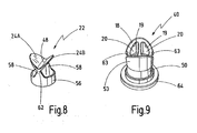
- Fig. 4 shows a further embodiment of a check valve according to the invention, which generally with respect to structure and function of the check valve of Fig. 3 equivalent.
- first sub-housing 40 has a cylindrical portion 53 on which the blocking element 22 is fixed. Furthermore, the first part housing 40 and the second part housing 42 are connected to each other via a seal 54.
- the check valve differs Fig. 4 from that of Fig. 3 by the manner of the formation of the attachment portion 26. While in the embodiment of the Fig. 3 the attachment portion is formed by a transverse web having a bead shape is in the embodiment of the Fig. 4 a fastening portion 26 is provided, which has a ring portion 56.
- the ring section 56 is received in an annular mounting recess 50 running around the cylinder section 53, so that the ring section 56 does not protrude in the radial direction relative to the outer contour of the cylinder section 53.
- the ring portion 56 is connected to the integrally connected locking tabs 24A, 24B via longitudinal web portions which will be described below.
- Fig. 5 It can be seen that four longitudinal channels 20 are formed on the first sub-housing 40, two longitudinal channels each being associated with a locking tab 24A, 24B.
- ring portion 56 is connected on radially opposite sides in each case via a longitudinal web portion 58 with a respective end of the transverse web 48, which connects the locking tabs 24A, 24B together.
- the longitudinal web portions 58 are preferably received on the first housing part 40 so that they do not protrude from an outer contour of the cylinder portion 53.
- radial recesses are provided on the outer circumference of the first part housing 40, as in Fig. 7 at 63 is shown.
- the locking member 22 and the first sub-housing 40 are each shown separately to illustrate the functions described above.
- the first sub-housing has at its rear end opposite the cylinder portion 53 radially projecting flange portion 64, by means of which the first sub-housing 40 can be connected to the second sub-housing 42 and sealed against this, as in Fig. 4 you can see.
- check valves described above can all be used as stationary, fixed check valves in any application. As fluid both liquid and gaseous substances are considered. However, due to the cylindrical shape of the first sub-housing 40, the first sub-housing 40 may also be formed as a piston, ie as a movable element, which is sealed relative to a second stationary housing. In this embodiment, the check valve according to the invention can be used in particular in a piston pump.
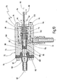
- FIG. 10 A preferred embodiment of a piston pump according to the invention is in Fig. 10 denoted by 70.
- the piston pump designed as a fluid pump 70 has a pump housing 72.
- the pump housing 72 includes a main housing 74 and a pressure-side lid 76 and a suction-side lid 78 which are attached to the main housing 74 at axially opposite ends.
- a longitudinal axis of the pump housing 72 is shown at 80.
- the pump housing 72 has four connecting pins 82 and associated nuts 84, of which in Fig. 10 only two are shown.
- the main housing 74 has an axial recess 86.
- the axial recess 86 is continuously connected via a piston guide 88 with the opposite end of the main housing 74.
- a piston 90 is guided displaceably in the longitudinal direction.
- the piston 90 has a longitudinal channel 92 which is open to the suction side. In this open end, a piston rod 94 is inserted from the suction side, which is connected via a suitable seal (not shown) with the piston 90. In the suction-side cover 78, an opening 96 is formed through which the piston rod 94 extends out of the pump housing 72. At 98, an actuator is indicated in schematic form, by means of which the piston rod 94 is movable in the longitudinal direction back and forth.
- annular sealing element 100 is inserted in the axial recess 86. This is located at a bottom of the axial recess 86, ie towards the pressure side.
- the annular sealing element 100 encloses the piston 90 and ensures a seal of the Piston 90 relative to the pump housing 72.
- a ring insert 102 is further used, which abuts the inner periphery of the axial recess 86 and extending in the axial direction of the suction-side cover 78 up to the annular sealing element 100.
- the annular sealing element 100 is thus fixed in the axial direction between the bottom of the axial recess 86 and the pressure-side end of the ring insert 102.
- the ring insert 102 is sealed relative to the main housing 74 by means of a seal not specified.
- a suction port 104 is formed, approximately in the middle thereof.
- the suction port 104 is radially aligned and opens into the axial recess 86.
- transverse channels are formed, via which the suction port 104 is connected to the interior of the ring insert 102.
- at least one transverse recess is formed on the piston 90, via which the interior of the ring insert 102 can be connected to the longitudinal channel 92.
- the longitudinal channel 92 is connected to the suction port 104 by suitable means, such as the described transverse channels.
- a first check valve 106 is formed at the pressure-side end of the piston 90.
- the check valve 106 is aligned so that a fluid flow in the direction of the pressure side is possible, a return flow is not possible.
- the first check valve 106 may be formed as one of the check valves 10 of the Fig. 4 to 9 , In this case, the piston 90 forms the valve housing 12 or the first housing 40.
- a pressure chamber 108 is formed.
- a continuous channel is formed, which opens into a pressure port.
- a second check valve 110 is arranged. This is preferably fixed to the pressure-side cover 76.
- the second check valve 110 may also as a check valve 10 according to one of Fig. 4 to 9 be formed and is arranged so that a flow from the pressure chamber 108 to the pressure port 112 is possible, a reverse fluid flow is prevented, however.
- a third check valve 111 may also be formed, which also allows a flow from the inlet to the suction port 104 and thus to the longitudinal channel 92, but prevents a backflow.
- the third check valve 111 is optionally provided for improving the efficiency, but is not essential to the function.
- a compensation chamber 114 is further provided.
- the compensation chamber 114 serves to receive fluid which flows back from the pressure chamber 108 between the piston 90 and the annular sealing element 100 during a working cycle (due to the sealing effect of the annular sealing element 100, which is not always necessarily 100% or due to the relatively high pressures within the pressure chamber 108). This exiting fluid is then forced into the compensation space 114 via transverse and longitudinal channels in the ring insert 102.
- the compensation chamber 114 is also connected to the suction port 104 via longitudinal and transverse channels in the ring insert 102.
- a flexible sealing arrangement 115 is provided, which seals the outside of the piston or the piston as a whole with respect to the opening 96. This prevents that entering the compensation chamber 114 entering fluid through the opening 96 to the outside.
- the sealing arrangement 115 is designed to accommodate movements of the piston 90 with respect to the pump housing 72.
- the flexible sealing arrangement 115 has a bellows section 116, which is arranged concentrically with the piston rod 94. One end of the bellows portion 116 is connected to a rear end of the piston 90. The other end is fixed to an axial inside of the suction-side lid 78, such that the interior of the bellows portion 116 is connected to the outside of the pump housing 72 (via the opening 96).
- the bellows section 116 in this case has a neutral cylinder contour 118, wherein each outer half-waves of the bellows contour outside the neutral cylinder contour 118 and inner half-waves of the bellows contour extend within the neutral cylinder contour 118.
- the circumference of the neutral cylinder contour 118 is matched to the outer circumference of the piston 90, such that the volume of the compensation chamber 114 is not or only insignificantly changed during axial movements of the piston 90. Accordingly, no significant force is exerted on the bellows section 116 or the sealing arrangement 115, in particular when using a liquid fluid (such as urea) via the compensation chamber 114. As a result, the sealing assembly 115 can be made very flexible without the risk of damaging or otherwise adversely affecting the assembly due to volume changes.
- Fig. 11 to 13 are individual parts of the fluid pump 70 shown. So is in Fig. 11 the piston 90 is shown and it can be seen that this at the front end valve seats 18 A, 18 B has (comparable to the valve seats of the embodiment of the check valve of Fig. 4 ). Furthermore, it can be seen that the longitudinal channel 92 substantially the longitudinal channel 20 of the check valve of Fig. 4 to 9 equivalent. In Fig. 11 Also shown at 122 is a transverse channel connecting the longitudinal channel 92 to the suction port 104. At the suction end of the piston 90, a flange portion 124 is further formed. This can serve as a stop for the piston 90 with respect to the pump housing 72 (or with respect to the ring insert 102). On the other hand, the flange portion 124 serves to define a pressure-side end of the bellows portion 116, between the flange portion 124 and a corresponding flange portion of the piston rod 94th
- ring sealing element 100 In Fig. 12 the ring sealing element 100 is shown.
- the annular sealing element 100 has an axial annular recess 126 towards the pressure side, such that on the outer circumference of the in Fig. 12 not shown piston abuts an annular sealing lip 128 which extends from the suction side to the pressure side.
- annular sealing element 100 By virtue of this design of the annular sealing element 100, on the one hand, a high sealing effect can be achieved. On the other hand, a wear occurring over the service life on the inner circumference of the sealing lip 128 can be compensated.
- Fig. 13 the flexible sealing assembly 115 is shown with the bellows portion 116.
- the sealing flange 120 can be seen, which is fixed in the assembled state between the suction-side end of the ring insert 102 and the inside of the suction-side cover 78. Furthermore, in Fig. 13 to recognize another axially opposite sealing flange 132 of the sealing assembly 115, wherein the further sealing flange 132 between the flange portion 124 of the piston 90 and a corresponding flange portion of the piston rod 94 is set to provide a suitable seal of the compensation chamber 114.
- FIGS. 14 to 17 the operation of a fluid pump 70 according to the invention is shown, the structure and operation of the fluid pump 70 of the Fig. 10 equivalent.
- Fig. 15 is shown that the piston is moved to the pressure side (piston position K2). In this case, a pressure which is greater than the fluid pressure at the pressure port 112 arises in the pressure chamber 108, so that the fluid is discharged via the second check valve 110 to the pressure port 112.
- Fig. 16 is the end position of the power stroke shown (piston position K3), in which the fluid 30 has been discharged as far as possible from the pressure chamber 108 via the second check valve 110 to the pressure side.
- the illustrated cross symbols each indicate that there is a higher pressure than other locations of the fluid pump 70.
- the flexible sealing assembly 115 is stretched in the maximum way.
- Fig. 17 shows the fluid pump 70 during a subsequent suction cycle.
- the piston 70 is moved back in the axial direction (piston position K4).
- the second check valve 110 closes and there is created in the pressure chamber 108, a negative pressure (represented by a triangular symbol).
- the first check valve 106 opens and the corresponding negative pressure is also present at the suction port 104, so that fluid 30 flows into the pressure chamber 108 via the suction port 104 and the longitudinal channels 92, as shown in FIG Fig. 17 shown by double arrows.
- the volume of the compensation chamber 114 remains at least approximately constant, so that no substantial forces are exerted on the flexible sealing arrangement 115.
- Fig. 18 11 shows an alternative embodiment of a flexible sealing arrangement 115, in the form of a diaphragm section 134, which extends from an outer circumference of the piston 90 to an inner circumference of the compensation chamber 114.
- the volume of the compensation chamber 114 changes during movements of the piston 90.
- the compensation chamber 114 acts as a pump chamber.
- the membrane portion 134 is interpreted in a corresponding manner. This embodiment is preferably used when using gaseous fluids.
- FIG. 12 shows another alternative embodiment of a sealing assembly 115 having a bellows portion 116 and a membrane portion 134.
- the use of gaseous or liquid fluids is conceivable.
- this can be applied to an inner side of the compensation chamber 114 (for example to the inside of the suction-side cover 78).
- the load on the membrane section can consequently be limited.
- Fig. 20 shows an air pump assembly 140 mounted on the axially rear, suction-side end of the fluid pump 70.
- the air pump assembly 140 is connected to an air space 142 of the flexible seal assembly 115, ie, a space inside the bellows portion 116.
- the air pump assembly 140 includes an air bearing channel 144 that surrounds at least a portion of the piston rod protruding from the pump housing 72 and is configured to support this piston rod portion by air. For reasons of clarity an actuator for actuating the piston rod 94 is not shown.
- the air bearing channel 144 is sealed by a seal 146 relative to the outside of the pump housing 72.
- the air pump assembly 140 preferably includes a first check valve 148 associated with a suction side of the air bearing channel 144 and a second check valve 150 associated with a pressure side of the air bearing channel 144.
- the first check valve 148 may, for example, be integrated in the pump housing 72 and connect a suction port to the opening 96.
- the second check valve 150 may be connected at an exit end of the air bearing channel 144 and with an outlet port.
- an air guide groove 192 may be provided on the outer circumference of the portion of the piston rod 94, formed, for example, like a drawn gun barrel ,
Landscapes
- Engineering & Computer Science (AREA)
- General Engineering & Computer Science (AREA)
- Mechanical Engineering (AREA)
- Details Of Reciprocating Pumps (AREA)
- Check Valves (AREA)
Applications Claiming Priority (2)
| Application Number | Priority Date | Filing Date | Title |
|---|---|---|---|
| DE200810006686 DE102008006686B4 (de) | 2008-01-21 | 2008-01-21 | Rückschlagventil |
| PCT/EP2009/000163 WO2009092537A2 (de) | 2008-01-21 | 2009-01-14 | Rückschlagventil und kolbenpumpe mit rückschlagventil |
Publications (2)
| Publication Number | Publication Date |
|---|---|
| EP2245348A2 EP2245348A2 (de) | 2010-11-03 |
| EP2245348B1 true EP2245348B1 (de) | 2014-10-01 |
Family
ID=40584696
Family Applications (1)
| Application Number | Title | Priority Date | Filing Date |
|---|---|---|---|
| EP20090704179 Active EP2245348B1 (de) | 2008-01-21 | 2009-01-14 | Rückschlagventil und kolbenpumpe mit rückschlagventil |
Country Status (5)
| Country | Link |
|---|---|
| US (1) | US8444401B2 (enExample) |
| EP (1) | EP2245348B1 (enExample) |
| JP (1) | JP5558367B2 (enExample) |
| DE (1) | DE102008006686B4 (enExample) |
| WO (1) | WO2009092537A2 (enExample) |
Cited By (1)
| Publication number | Priority date | Publication date | Assignee | Title |
|---|---|---|---|---|
| DE102022116238A1 (de) * | 2022-06-29 | 2024-01-04 | Zf Cv Systems Europe Bv | Rückschlagventil für einen Kompressor eines Kraftfahrzeugs, Kompressor sowie betreffende Verwendung |
Families Citing this family (21)
| Publication number | Priority date | Publication date | Assignee | Title |
|---|---|---|---|---|
| GB2433701B (en) * | 2005-12-29 | 2010-03-24 | Medinnova As | Valve for a breathing apparatus |
| DE102008056960B3 (de) * | 2008-11-03 | 2010-04-22 | Prettl, Rolf | Ventil |
| DE102009018930B4 (de) * | 2009-04-28 | 2013-08-08 | Rolf Prettl | Rückschlagventil |
| DE102009042231A1 (de) | 2009-09-18 | 2011-04-21 | Simmoteit, Robert, Dr. | Spülverfahren und verschließbare Spülvorrichtung |
| US8800167B2 (en) * | 2009-09-19 | 2014-08-12 | Harold S. Doyle | Pneumatic inflating device contained entirely within shoe sole |
| DE102011001603A1 (de) | 2010-11-15 | 2012-05-16 | Illinois Tool Works, Inc. | Vorrichtung zum Ausbringen von Reifendichtmittel aus einem Behälter |
| JP2013085740A (ja) * | 2011-10-19 | 2013-05-13 | Mitsubishi Electric Corp | 食器洗浄機 |
| US9004093B2 (en) | 2012-05-22 | 2015-04-14 | B/E Aerospace, Inc. | Compact check valve for aircraft galley plumbing system |
| DE102012011975B4 (de) | 2012-06-15 | 2018-09-20 | Rolf Prettl | Ventilanordnung und Tankmodul für ein Harnstoffeinspritzsystem |
| US9527658B2 (en) * | 2012-08-08 | 2016-12-27 | James H. Martin | Metering valve fillable through the valve |
| EP2840191B1 (de) * | 2013-08-21 | 2017-06-14 | Geberit International AG | Geruchsverschlussvorrichtung |
| DE102013110400A1 (de) | 2013-09-20 | 2015-03-26 | Getrag Getriebe- Und Zahnradfabrik Hermann Hagenmeyer Gmbh & Cie Kg | Innenzahnradpumpe und Hydraulikkreis für Kraftfahrzeugantriebsstrang |
| DE102014115548A1 (de) | 2014-10-27 | 2016-04-28 | Getrag Getriebe- Und Zahnradfabrik Hermann Hagenmeyer Gmbh & Cie Kg | Innenzahnradpumpe und Pumpverfahren |
| SI3298276T1 (sl) | 2015-05-21 | 2021-08-31 | Henkel IP & Holding GmbH | Izničevalni protipovratni ventil |
| BR102017013190A2 (pt) * | 2017-06-19 | 2019-01-15 | Whirlpool S.A. | estrutura para montagem de válvula tipo palheta |
| CN110052444B (zh) * | 2019-05-30 | 2021-05-14 | 冯志高 | 一种黄芪清洗装置 |
| DE102020108056B4 (de) | 2020-03-24 | 2022-06-23 | Mann+Hummel Gmbh | Partikelaustragsvorrichtung, Filteranordnung und Absaugrohr |
| DE102020108055A1 (de) | 2020-03-24 | 2021-09-30 | Mann+Hummel Gmbh | Partikelaustragsvorrichtung, Filteranordnung und Verfahren |
| KR102662333B1 (ko) * | 2021-11-02 | 2024-04-29 | 김영교 | 에어 밸브 |
| DE102022132355A1 (de) * | 2022-12-06 | 2024-06-06 | Elringklinger Ag | Rückschlagventil |
| CN120557400B (zh) * | 2025-07-31 | 2025-09-26 | 烟台新瑞环保科技有限公司 | 一种改进型鸭嘴型阀 |
Family Cites Families (23)
| Publication number | Priority date | Publication date | Assignee | Title |
|---|---|---|---|---|
| DE408499C (de) * | 1922-11-02 | 1925-01-20 | Ag Deutsche Maschf | Ein- oder mehrstufiger Kolbenkompressor mit Ausgleich des Kraftverbrauchs beim Hin- und Hergang des Kolbens |
| US3312237A (en) * | 1964-05-06 | 1967-04-04 | Mon George | Bicuspid heart valve |
| JPS5131365Y2 (enExample) * | 1972-11-06 | 1976-08-06 | ||
| JPS5537684Y2 (enExample) * | 1978-03-30 | 1980-09-04 | ||
| JPS5522517U (enExample) * | 1978-07-31 | 1980-02-13 | ||
| JPS56127470U (enExample) * | 1980-02-29 | 1981-09-28 | ||
| JPS60146972A (ja) * | 1984-01-11 | 1985-08-02 | Matsushita Refrig Co | パイプ内装型チエツクバルブ |
| JPS6412083A (en) * | 1987-07-03 | 1989-01-17 | Kurashiki Boseki Kk | Reciprocating pump |
| SE462782B (sv) * | 1989-01-16 | 1990-09-03 | Guenther Georg Nabholz | Implanterbar blodpump |
| FR2695965B1 (fr) * | 1992-09-23 | 1994-10-21 | Kremlin | Pompe munie, sur une ou plusieurs tiges de pistons, d'un soufflet d'étanchéité. |
| US5245956A (en) * | 1993-01-11 | 1993-09-21 | Barry Davidson | Reed valve assembly |
| US5415531A (en) * | 1994-04-06 | 1995-05-16 | Binks Manufacturing Company | Piston pump for fluent materials |
| US5518026A (en) * | 1994-09-30 | 1996-05-21 | G. T. Products, Inc. | Filler neck butterfly check valve |
| JPH11159474A (ja) * | 1997-11-28 | 1999-06-15 | Japan Pionics Co Ltd | 液体材料流量制御ポンプ |
| AT3873U1 (de) * | 1999-03-29 | 2000-09-25 | Tesma Motoren Getriebetechnik | Rückschlagventil für ein einfüllrohr eines treibstofftanks eines kraftfahrzeuges |
| JP2005098280A (ja) * | 2003-08-19 | 2005-04-14 | Seiko Instruments Inc | 液体吐出装置 |
| JP4143841B2 (ja) * | 2003-09-18 | 2008-09-03 | 株式会社アドヴィックス | ピストンポンプ |
| KR100514409B1 (ko) * | 2004-03-22 | 2005-09-09 | 현대모비스 주식회사 | 자동차 안티 록 브레이크 시스템의 펌프 |
| US20060045782A1 (en) * | 2004-08-27 | 2006-03-02 | Lincoln Industrial Corporation | Low-friction reciprocating pump |
| US20070056648A1 (en) * | 2005-09-09 | 2007-03-15 | Eaton Corporation | Two-piece valve |
| JP4721880B2 (ja) * | 2005-11-25 | 2011-07-13 | 京セラ株式会社 | プランジャポンプおよびこれを用いたポンプ装置 |
| US20070157970A1 (en) * | 2006-01-11 | 2007-07-12 | Sunonwealth Electric Machine Industry Co., Ltd. | Check valve for fluid |
| DE102006040250A1 (de) | 2006-08-28 | 2008-03-06 | Robert Bosch Gmbh | Vorrichtung zum Fallschutz von Drehratensensoren |
-
2008
- 2008-01-21 DE DE200810006686 patent/DE102008006686B4/de not_active Expired - Fee Related
-
2009
- 2009-01-14 EP EP20090704179 patent/EP2245348B1/de active Active
- 2009-01-14 JP JP2010542573A patent/JP5558367B2/ja not_active Expired - Fee Related
- 2009-01-14 WO PCT/EP2009/000163 patent/WO2009092537A2/de not_active Ceased
-
2010
- 2010-07-13 US US12/835,484 patent/US8444401B2/en not_active Expired - Fee Related
Cited By (1)
| Publication number | Priority date | Publication date | Assignee | Title |
|---|---|---|---|---|
| DE102022116238A1 (de) * | 2022-06-29 | 2024-01-04 | Zf Cv Systems Europe Bv | Rückschlagventil für einen Kompressor eines Kraftfahrzeugs, Kompressor sowie betreffende Verwendung |
Also Published As
| Publication number | Publication date |
|---|---|
| WO2009092537A2 (de) | 2009-07-30 |
| DE102008006686A1 (de) | 2009-07-30 |
| JP5558367B2 (ja) | 2014-07-23 |
| EP2245348A2 (de) | 2010-11-03 |
| US20100329911A1 (en) | 2010-12-30 |
| WO2009092537A3 (de) | 2010-10-07 |
| JP2011512490A (ja) | 2011-04-21 |
| US8444401B2 (en) | 2013-05-21 |
| DE102008006686B4 (de) | 2010-03-18 |
Similar Documents
| Publication | Publication Date | Title |
|---|---|---|
| EP2245348B1 (de) | Rückschlagventil und kolbenpumpe mit rückschlagventil | |
| EP2425162B1 (de) | Rückschlagventil | |
| EP1671031B1 (de) | Fluidpumpe, insbesondere kraftstoffhochdruckpumpe, mit druckdämpfer | |
| DE4291026C2 (de) | Schwingungsdämpfer für ein gepumptes Flüssigkeitssystem | |
| EP2294316B1 (de) | Kolbenpumpe einer hydraulischen fahrzeugbremsanlage | |
| EP2049794B1 (de) | Dicht- und führungseinrichtung für einen kolben einer kolbenpumpe | |
| DE4333578B4 (de) | Hydraulikpumpe | |
| DE102006023157B3 (de) | Dichtungsanordnung zur Druckentlastung | |
| DE102008063241A1 (de) | Hauptzylinder | |
| DE102009046313A1 (de) | Kolbenanordnung einer Kolbenpumpe | |
| EP2815129A1 (de) | Dichtungsanordnung und pumpe mit einer dichtungsanordnung | |
| DE202013105650U1 (de) | Kolbenpumpe | |
| DE19854715A1 (de) | Kolbenpumpe | |
| DE10302043A1 (de) | Kraftstoffhochdruckpumpe mit Kugelventil im Niederdruck-Einlass | |
| DE102007058759A1 (de) | Rückschlagventil für eine Schmierstoffpumpe sowie Schmierstoffpumpe | |
| DE102008056960B3 (de) | Ventil | |
| DE3043054A1 (de) | Fluegelzellenpume | |
| DE102019210653A1 (de) | Ventilvorrichtung für ein Kraftstoffversorgungssystem einer Brennkraftmaschine | |
| DE102013214968A1 (de) | Ventil für ein Rücklaufteil eines Kraftstoffeinspritzsystems | |
| DE112019001146T5 (de) | Kettenspanner | |
| EP3237729B1 (de) | Expansionsmaschine mit wellendichtring und ventil | |
| DE102016216350A1 (de) | Kolbenmaschine, insbesondere Kolbenpumpe zur Förderung von Druckmittel in einer elektronisch schlupfregelbaren Fahrzeugbremsanlage und elektronisch schlupfregelbare Fahrzeugbremsanlage | |
| DE1425729A1 (de) | Ventil fuer Gaskompressoren | |
| DE10029226C2 (de) | Regelsicherheitsblock mit Schwingungsdämpfer für Hochdruckreiniger | |
| DE202020104630U1 (de) | Tandemdichtungssystem und hydraulischer Stellantrieb |
Legal Events
| Date | Code | Title | Description |
|---|---|---|---|
| PUAI | Public reference made under article 153(3) epc to a published international application that has entered the european phase |
Free format text: ORIGINAL CODE: 0009012 |
|
| 17P | Request for examination filed |
Effective date: 20100817 |
|
| AK | Designated contracting states |
Kind code of ref document: A2 Designated state(s): AT BE BG CH CY CZ DE DK EE ES FI FR GB GR HR HU IE IS IT LI LT LU LV MC MK MT NL NO PL PT RO SE SI SK TR |
|
| AX | Request for extension of the european patent |
Extension state: AL BA RS |
|
| R17D | Deferred search report published (corrected) |
Effective date: 20101007 |
|
| DAX | Request for extension of the european patent (deleted) | ||
| 17Q | First examination report despatched |
Effective date: 20120914 |
|
| GRAP | Despatch of communication of intention to grant a patent |
Free format text: ORIGINAL CODE: EPIDOSNIGR1 |
|
| INTG | Intention to grant announced |
Effective date: 20140410 |
|
| GRAS | Grant fee paid |
Free format text: ORIGINAL CODE: EPIDOSNIGR3 |
|
| GRAA | (expected) grant |
Free format text: ORIGINAL CODE: 0009210 |
|
| AK | Designated contracting states |
Kind code of ref document: B1 Designated state(s): AT BE BG CH CY CZ DE DK EE ES FI FR GB GR HR HU IE IS IT LI LT LU LV MC MK MT NL NO PL PT RO SE SI SK TR |
|
| REG | Reference to a national code |
Ref country code: GB Ref legal event code: FG4D Free format text: NOT ENGLISH |
|
| REG | Reference to a national code |
Ref country code: AT Ref legal event code: REF Ref document number: 689702 Country of ref document: AT Kind code of ref document: T Effective date: 20141015 Ref country code: CH Ref legal event code: EP |
|
| REG | Reference to a national code |
Ref country code: IE Ref legal event code: FG4D Free format text: LANGUAGE OF EP DOCUMENT: GERMAN |
|
| REG | Reference to a national code |
Ref country code: DE Ref legal event code: R096 Ref document number: 502009010035 Country of ref document: DE Effective date: 20141113 |
|
| REG | Reference to a national code |
Ref country code: NL Ref legal event code: VDEP Effective date: 20141001 |
|
| REG | Reference to a national code |
Ref country code: LT Ref legal event code: MG4D |
|
| PG25 | Lapsed in a contracting state [announced via postgrant information from national office to epo] |
Ref country code: NL Free format text: LAPSE BECAUSE OF FAILURE TO SUBMIT A TRANSLATION OF THE DESCRIPTION OR TO PAY THE FEE WITHIN THE PRESCRIBED TIME-LIMIT Effective date: 20141001 |
|
| PG25 | Lapsed in a contracting state [announced via postgrant information from national office to epo] |
Ref country code: FI Free format text: LAPSE BECAUSE OF FAILURE TO SUBMIT A TRANSLATION OF THE DESCRIPTION OR TO PAY THE FEE WITHIN THE PRESCRIBED TIME-LIMIT Effective date: 20141001 Ref country code: IS Free format text: LAPSE BECAUSE OF FAILURE TO SUBMIT A TRANSLATION OF THE DESCRIPTION OR TO PAY THE FEE WITHIN THE PRESCRIBED TIME-LIMIT Effective date: 20150201 Ref country code: ES Free format text: LAPSE BECAUSE OF FAILURE TO SUBMIT A TRANSLATION OF THE DESCRIPTION OR TO PAY THE FEE WITHIN THE PRESCRIBED TIME-LIMIT Effective date: 20141001 Ref country code: PT Free format text: LAPSE BECAUSE OF FAILURE TO SUBMIT A TRANSLATION OF THE DESCRIPTION OR TO PAY THE FEE WITHIN THE PRESCRIBED TIME-LIMIT Effective date: 20150202 Ref country code: CZ Free format text: LAPSE BECAUSE OF FAILURE TO SUBMIT A TRANSLATION OF THE DESCRIPTION OR TO PAY THE FEE WITHIN THE PRESCRIBED TIME-LIMIT Effective date: 20141001 Ref country code: NO Free format text: LAPSE BECAUSE OF FAILURE TO SUBMIT A TRANSLATION OF THE DESCRIPTION OR TO PAY THE FEE WITHIN THE PRESCRIBED TIME-LIMIT Effective date: 20150101 Ref country code: LT Free format text: LAPSE BECAUSE OF FAILURE TO SUBMIT A TRANSLATION OF THE DESCRIPTION OR TO PAY THE FEE WITHIN THE PRESCRIBED TIME-LIMIT Effective date: 20141001 |
|
| PG25 | Lapsed in a contracting state [announced via postgrant information from national office to epo] |
Ref country code: HR Free format text: LAPSE BECAUSE OF FAILURE TO SUBMIT A TRANSLATION OF THE DESCRIPTION OR TO PAY THE FEE WITHIN THE PRESCRIBED TIME-LIMIT Effective date: 20141001 Ref country code: LV Free format text: LAPSE BECAUSE OF FAILURE TO SUBMIT A TRANSLATION OF THE DESCRIPTION OR TO PAY THE FEE WITHIN THE PRESCRIBED TIME-LIMIT Effective date: 20141001 Ref country code: CY Free format text: LAPSE BECAUSE OF FAILURE TO SUBMIT A TRANSLATION OF THE DESCRIPTION OR TO PAY THE FEE WITHIN THE PRESCRIBED TIME-LIMIT Effective date: 20141001 Ref country code: SE Free format text: LAPSE BECAUSE OF FAILURE TO SUBMIT A TRANSLATION OF THE DESCRIPTION OR TO PAY THE FEE WITHIN THE PRESCRIBED TIME-LIMIT Effective date: 20141001 Ref country code: PL Free format text: LAPSE BECAUSE OF FAILURE TO SUBMIT A TRANSLATION OF THE DESCRIPTION OR TO PAY THE FEE WITHIN THE PRESCRIBED TIME-LIMIT Effective date: 20141001 Ref country code: GR Free format text: LAPSE BECAUSE OF FAILURE TO SUBMIT A TRANSLATION OF THE DESCRIPTION OR TO PAY THE FEE WITHIN THE PRESCRIBED TIME-LIMIT Effective date: 20150102 |
|
| PG25 | Lapsed in a contracting state [announced via postgrant information from national office to epo] |
Ref country code: BE Free format text: LAPSE BECAUSE OF NON-PAYMENT OF DUE FEES Effective date: 20150131 |
|
| REG | Reference to a national code |
Ref country code: DE Ref legal event code: R097 Ref document number: 502009010035 Country of ref document: DE |
|
| PG25 | Lapsed in a contracting state [announced via postgrant information from national office to epo] |
Ref country code: EE Free format text: LAPSE BECAUSE OF FAILURE TO SUBMIT A TRANSLATION OF THE DESCRIPTION OR TO PAY THE FEE WITHIN THE PRESCRIBED TIME-LIMIT Effective date: 20141001 Ref country code: RO Free format text: LAPSE BECAUSE OF FAILURE TO SUBMIT A TRANSLATION OF THE DESCRIPTION OR TO PAY THE FEE WITHIN THE PRESCRIBED TIME-LIMIT Effective date: 20141001 Ref country code: SK Free format text: LAPSE BECAUSE OF FAILURE TO SUBMIT A TRANSLATION OF THE DESCRIPTION OR TO PAY THE FEE WITHIN THE PRESCRIBED TIME-LIMIT Effective date: 20141001 Ref country code: DK Free format text: LAPSE BECAUSE OF FAILURE TO SUBMIT A TRANSLATION OF THE DESCRIPTION OR TO PAY THE FEE WITHIN THE PRESCRIBED TIME-LIMIT Effective date: 20141001 |
|
| PLBE | No opposition filed within time limit |
Free format text: ORIGINAL CODE: 0009261 |
|
| STAA | Information on the status of an ep patent application or granted ep patent |
Free format text: STATUS: NO OPPOSITION FILED WITHIN TIME LIMIT |
|
| REG | Reference to a national code |
Ref country code: CH Ref legal event code: PL |
|
| PG25 | Lapsed in a contracting state [announced via postgrant information from national office to epo] |
Ref country code: LU Free format text: LAPSE BECAUSE OF FAILURE TO SUBMIT A TRANSLATION OF THE DESCRIPTION OR TO PAY THE FEE WITHIN THE PRESCRIBED TIME-LIMIT Effective date: 20150114 |
|
| 26N | No opposition filed |
Effective date: 20150702 |
|
| PG25 | Lapsed in a contracting state [announced via postgrant information from national office to epo] |
Ref country code: MC Free format text: LAPSE BECAUSE OF FAILURE TO SUBMIT A TRANSLATION OF THE DESCRIPTION OR TO PAY THE FEE WITHIN THE PRESCRIBED TIME-LIMIT Effective date: 20141001 |
|
| PG25 | Lapsed in a contracting state [announced via postgrant information from national office to epo] |
Ref country code: CH Free format text: LAPSE BECAUSE OF NON-PAYMENT OF DUE FEES Effective date: 20150131 Ref country code: LI Free format text: LAPSE BECAUSE OF NON-PAYMENT OF DUE FEES Effective date: 20150131 |
|
| REG | Reference to a national code |
Ref country code: IE Ref legal event code: MM4A |
|
| REG | Reference to a national code |
Ref country code: FR Ref legal event code: PLFP Year of fee payment: 8 |
|
| PG25 | Lapsed in a contracting state [announced via postgrant information from national office to epo] |
Ref country code: IE Free format text: LAPSE BECAUSE OF NON-PAYMENT OF DUE FEES Effective date: 20150114 |
|
| PG25 | Lapsed in a contracting state [announced via postgrant information from national office to epo] |
Ref country code: SI Free format text: LAPSE BECAUSE OF FAILURE TO SUBMIT A TRANSLATION OF THE DESCRIPTION OR TO PAY THE FEE WITHIN THE PRESCRIBED TIME-LIMIT Effective date: 20141001 |
|
| REG | Reference to a national code |
Ref country code: AT Ref legal event code: MM01 Ref document number: 689702 Country of ref document: AT Kind code of ref document: T Effective date: 20150114 |
|
| PG25 | Lapsed in a contracting state [announced via postgrant information from national office to epo] |
Ref country code: AT Free format text: LAPSE BECAUSE OF NON-PAYMENT OF DUE FEES Effective date: 20150114 |
|
| PG25 | Lapsed in a contracting state [announced via postgrant information from national office to epo] |
Ref country code: MT Free format text: LAPSE BECAUSE OF FAILURE TO SUBMIT A TRANSLATION OF THE DESCRIPTION OR TO PAY THE FEE WITHIN THE PRESCRIBED TIME-LIMIT Effective date: 20141001 |
|
| REG | Reference to a national code |
Ref country code: FR Ref legal event code: PLFP Year of fee payment: 9 |
|
| PG25 | Lapsed in a contracting state [announced via postgrant information from national office to epo] |
Ref country code: HU Free format text: LAPSE BECAUSE OF FAILURE TO SUBMIT A TRANSLATION OF THE DESCRIPTION OR TO PAY THE FEE WITHIN THE PRESCRIBED TIME-LIMIT; INVALID AB INITIO Effective date: 20090114 Ref country code: BG Free format text: LAPSE BECAUSE OF FAILURE TO SUBMIT A TRANSLATION OF THE DESCRIPTION OR TO PAY THE FEE WITHIN THE PRESCRIBED TIME-LIMIT Effective date: 20141001 |
|
| PG25 | Lapsed in a contracting state [announced via postgrant information from national office to epo] |
Ref country code: TR Free format text: LAPSE BECAUSE OF FAILURE TO SUBMIT A TRANSLATION OF THE DESCRIPTION OR TO PAY THE FEE WITHIN THE PRESCRIBED TIME-LIMIT Effective date: 20141001 |
|
| REG | Reference to a national code |
Ref country code: FR Ref legal event code: PLFP Year of fee payment: 10 |
|
| PG25 | Lapsed in a contracting state [announced via postgrant information from national office to epo] |
Ref country code: MK Free format text: LAPSE BECAUSE OF FAILURE TO SUBMIT A TRANSLATION OF THE DESCRIPTION OR TO PAY THE FEE WITHIN THE PRESCRIBED TIME-LIMIT Effective date: 20141001 |
|
| PGFP | Annual fee paid to national office [announced via postgrant information from national office to epo] |
Ref country code: SI Payment date: 20190110 Year of fee payment: 12 Ref country code: IT Payment date: 20190124 Year of fee payment: 11 Ref country code: FR Payment date: 20190124 Year of fee payment: 11 |
|
| GBPC | Gb: european patent ceased through non-payment of renewal fee |
Effective date: 20200114 |
|
| PG25 | Lapsed in a contracting state [announced via postgrant information from national office to epo] |
Ref country code: GB Free format text: LAPSE BECAUSE OF NON-PAYMENT OF DUE FEES Effective date: 20200114 Ref country code: FR Free format text: LAPSE BECAUSE OF NON-PAYMENT OF DUE FEES Effective date: 20200131 |
|
| PG25 | Lapsed in a contracting state [announced via postgrant information from national office to epo] |
Ref country code: IT Free format text: LAPSE BECAUSE OF NON-PAYMENT OF DUE FEES Effective date: 20200114 |
|
| PGFP | Annual fee paid to national office [announced via postgrant information from national office to epo] |
Ref country code: DE Payment date: 20250226 Year of fee payment: 17 |