EP2244602B1 - Drehscheibe zur stützung beladener flächen - Google Patents
Drehscheibe zur stützung beladener flächen Download PDFInfo
- Publication number
- EP2244602B1 EP2244602B1 EP09712430A EP09712430A EP2244602B1 EP 2244602 B1 EP2244602 B1 EP 2244602B1 EP 09712430 A EP09712430 A EP 09712430A EP 09712430 A EP09712430 A EP 09712430A EP 2244602 B1 EP2244602 B1 EP 2244602B1
- Authority
- EP
- European Patent Office
- Prior art keywords
- turntable according
- turntable
- previous
- upper half
- piston
- Prior art date
- Legal status (The legal status is an assumption and is not a legal conclusion. Google has not performed a legal analysis and makes no representation as to the accuracy of the status listed.)
- Not-in-force
Links
- 230000008878 coupling Effects 0.000 claims description 9
- 238000010168 coupling process Methods 0.000 claims description 9
- 238000005859 coupling reaction Methods 0.000 claims description 9
- 230000001105 regulatory effect Effects 0.000 claims description 9
- 238000009792 diffusion process Methods 0.000 claims description 7
- 239000007788 liquid Substances 0.000 claims description 4
- 239000000853 adhesive Substances 0.000 description 4
- 230000001070 adhesive effect Effects 0.000 description 4
- 230000015572 biosynthetic process Effects 0.000 description 4
- 238000005755 formation reaction Methods 0.000 description 4
- 238000007789 sealing Methods 0.000 description 4
- 230000005484 gravity Effects 0.000 description 3
- 238000004519 manufacturing process Methods 0.000 description 3
- 230000000694 effects Effects 0.000 description 2
- 230000000295 complement effect Effects 0.000 description 1
- 238000013016 damping Methods 0.000 description 1
- 230000003247 decreasing effect Effects 0.000 description 1
- 238000006073 displacement reaction Methods 0.000 description 1
- 208000002173 dizziness Diseases 0.000 description 1
- 230000007613 environmental effect Effects 0.000 description 1
- 230000000763 evoking effect Effects 0.000 description 1
- 230000007717 exclusion Effects 0.000 description 1
- 230000005923 long-lasting effect Effects 0.000 description 1
- 238000012423 maintenance Methods 0.000 description 1
- 238000002360 preparation method Methods 0.000 description 1
- 230000002035 prolonged effect Effects 0.000 description 1
- 230000009469 supplementation Effects 0.000 description 1
Images

Classifications
-
- A—HUMAN NECESSITIES
- A47—FURNITURE; DOMESTIC ARTICLES OR APPLIANCES; COFFEE MILLS; SPICE MILLS; SUCTION CLEANERS IN GENERAL
- A47B—TABLES; DESKS; OFFICE FURNITURE; CABINETS; DRAWERS; GENERAL DETAILS OF FURNITURE
- A47B11/00—Tables with tops revolvable on vertical spindles
-
- A—HUMAN NECESSITIES
- A47—FURNITURE; DOMESTIC ARTICLES OR APPLIANCES; COFFEE MILLS; SPICE MILLS; SUCTION CLEANERS IN GENERAL
- A47C—CHAIRS; SOFAS; BEDS
- A47C1/00—Chairs adapted for special purposes
- A47C1/14—Beach chairs ; Chairs for outdoor use, e.g. chairs for relaxation or sun-tanning
-
- A—HUMAN NECESSITIES
- A47—FURNITURE; DOMESTIC ARTICLES OR APPLIANCES; COFFEE MILLS; SPICE MILLS; SUCTION CLEANERS IN GENERAL
- A47C—CHAIRS; SOFAS; BEDS
- A47C3/00—Chairs characterised by structural features; Chairs or stools with rotatable or vertically-adjustable seats
- A47C3/18—Chairs or stools with rotatable seat
-
- A—HUMAN NECESSITIES
- A47—FURNITURE; DOMESTIC ARTICLES OR APPLIANCES; COFFEE MILLS; SPICE MILLS; SUCTION CLEANERS IN GENERAL
- A47F—SPECIAL FURNITURE, FITTINGS, OR ACCESSORIES FOR SHOPS, STOREHOUSES, BARS, RESTAURANTS OR THE LIKE; PAYING COUNTERS
- A47F5/00—Show stands, hangers, or shelves characterised by their constructional features
- A47F5/02—Rotary display stands
- A47F5/025—Rotary display stands having mechanical drive, e.g. turntables
-
- A—HUMAN NECESSITIES
- A63—SPORTS; GAMES; AMUSEMENTS
- A63J—DEVICES FOR THEATRES, CIRCUSES, OR THE LIKE; CONJURING APPLIANCES OR THE LIKE
- A63J1/00—Stage arrangements
- A63J1/02—Scenery; Curtains; Other decorations; Means for moving same
-
- G—PHYSICS
- G09—EDUCATION; CRYPTOGRAPHY; DISPLAY; ADVERTISING; SEALS
- G09B—EDUCATIONAL OR DEMONSTRATION APPLIANCES; APPLIANCES FOR TEACHING, OR COMMUNICATING WITH, THE BLIND, DEAF OR MUTE; MODELS; PLANETARIA; GLOBES; MAPS; DIAGRAMS
- G09B19/00—Teaching not covered by other main groups of this subclass
-
- G—PHYSICS
- G09—EDUCATION; CRYPTOGRAPHY; DISPLAY; ADVERTISING; SEALS
- G09B—EDUCATIONAL OR DEMONSTRATION APPLIANCES; APPLIANCES FOR TEACHING, OR COMMUNICATING WITH, THE BLIND, DEAF OR MUTE; MODELS; PLANETARIA; GLOBES; MAPS; DIAGRAMS
- G09B25/00—Models for purposes not provided for in G09B23/00, e.g. full-sized devices for demonstration purposes
- G09B25/02—Models for purposes not provided for in G09B23/00, e.g. full-sized devices for demonstration purposes of industrial processes; of machinery
-
- A—HUMAN NECESSITIES
- A61—MEDICAL OR VETERINARY SCIENCE; HYGIENE
- A61N—ELECTROTHERAPY; MAGNETOTHERAPY; RADIATION THERAPY; ULTRASOUND THERAPY
- A61N5/00—Radiation therapy
- A61N5/06—Radiation therapy using light
- A61N2005/0635—Radiation therapy using light characterised by the body area to be irradiated
- A61N2005/0636—Irradiating the whole body
- A61N2005/064—Irradiating the whole body in a vertical position
- A61N2005/0641—Irradiating the whole body in a vertical position with rotation of the patient
Definitions
- Subject of this invention is a turntable for vertical support of loaded horizontal surfaces, that has an upper and a lower half, between which it includes a vertical rotatable guiding element.
- the turntable according to the introductory paragraph in its most general form is such that within the guiding element a braking element is arranged that limits vertical downward movement of the loaded horizontal surface to a given speed.
- the guiding element includes a threaded part that converts vertical downward movement into rotational motion, where the upper half during his downward movement engaged into the threaded part, through it is connected to the lower part by mechanical coupling for rotation transfer.
- the braking element is configured so that - after expiration of loaded condition - it allows backward movement of the upper half relatively to the lower part practically without or with light braking, and during its downward movement the upper half is coupled to the lower part without mechanical coupling for rotation transfer.
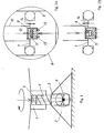
- a turntable according to the invention which serves for vertical support of a practically horizontal surface.
- the turntable consists of two parts, of an upper' half 1 and a lower half 2 with a guiding element 3 between them that includes a threaded part 4 of fixed position relatively to the lower part 2.
- This threaded part 4 is a thread with high pitch with one or more starts established in the internal cavity 5 and in the inserted envelope of the upper part of the guiding element 3 as well as the connecting complementing formation.
- Such a complementary formation can be e.g. a full thread or only one or more protrusions from the cylindrical shell surface of the cavity 5.
- a braking element 6 that causes some braking of various extent against vertical movement between the lower half 1 and the upper half 2 depending on the direction.
- the braking is large and dampens the motion to extremely slow.
- the braking is minimal, almost zero.
- a mechanism with a piston 7 and a non-return valve 8, enlarged in Fig. 2A on the lower part of the guiding element 3 we show a mechanism with a piston 7 and a non-return valve 8, enlarged in Fig. 2A .
- a piston 7 is placed that air tightly seals the lower volume of the cylinder 9. Air closed here can flow outward or inward only through a valve 8.
- contacting surfaces roughened, abrasive or by forming at least on one of them small-sized grooves, channels, chamfers.
- Air diffusion ability of artificial diffusing structure worked out in such a way in contacting surfaces can be regulated.
- previously known solutions exist and are well applicable.
- a small-sized air diffusion opening 14 e.g. a bore, which has a minimal role in the position according to Fig. 2A when the valve 8 is open, but when according to Fig. 2B the valve 8 is closed - and now we assume perfect closure - then flow-out from the closed room can be performed only through this opening 14.
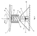
- FIG. 3 Another possible design form is shown in Fig. 3 where a part of the guiding element 3 is an intermediate element 15, which - as a screw nut mechanism - is in constant connection with the threaded part 4. Downward movement of this intermediate element 15 is limited by the braking element 6. Upper horizontal surface of the intermediate element 15 - as adhesive coupling - engages on the internal lower surface 16 of the cavity 5 formed for the upper half 1. This adhesive coupling-like engagement, however, will proceed only when a downward force is effected onto the upper half 1, therefore this presses it with the intermediate element 15.
- the turntable includes a returning element that in case of expiration of the loaded condition moves the braking element 6 into its upper position.
- the returning element expediently is a spring 18 that is supported on the lower part of the cylinder 8 and returns the piston 7 to its upper position when the load originated from gravity and exceeding the spring force expires.
- manual operation can be applied additionally when we simply draw up the upper half 1.
- the turntable according to the invention practically serves for vertical support of horizontal surfaces and this opens various areas for application.
- the solution has an important advantage that no energy supply is required.
- Such application area can be, for example, establishment of such sunbath bed that rotates at a predetermined speed and thereby the person lying on it is turned towards the sunshine. This makes sun-tan more uniform and reduces the risk of concentrated burning of the skin.
- rotation speed must be adjusted so that the turnaround takes several minutes or several decades of minutes.
- the speed of rotation must be so low that the user does not detect it, as fast rotation can be disturbing, and may cause even dizziness, for example.
- turntable can be its configuration as a warehouse- or exhibition tool for product fairs.
- the turntable can be applied as a school training or demonstration tool that shows an object or phenomenon from its several sides for many people.
- the turntable according to the invention may be suitable also for moving of theatrical sceneries or stages.
- the invention is suitable for all such tasks where one or more objects must be made available or visible from different directions without additional source of energy, and this operation can be repeated after expiry of a given time interval by human intervention.
- the part of the turntable that establishes rotation, the guiding element can be prepared also in small size, and for this the necessary base and upper supporting surfaces, components can be inserted separately, thereby they can be easily assembled and disassembled and transported. Place of utilisation does not require any ground- or other preparation.
Landscapes
- Engineering & Computer Science (AREA)
- Business, Economics & Management (AREA)
- Physics & Mathematics (AREA)
- Educational Administration (AREA)
- Educational Technology (AREA)
- General Physics & Mathematics (AREA)
- Theoretical Computer Science (AREA)
- General Health & Medical Sciences (AREA)
- Mechanical Engineering (AREA)
- Dentistry (AREA)
- Health & Medical Sciences (AREA)
- Entrepreneurship & Innovation (AREA)
- Actuator (AREA)
- Transmission Devices (AREA)
- Coating Apparatus (AREA)
Claims (18)
- Drehscheibe zur senkrechten Stütze von im Wesentlichen waagerecht beladenen Flächen, die eine obere (1) und eine untere Hälfte (2) umfasst, zwischen denen sie ein senkrecht gerichtetes drehbares Führungselement umfasst, dadurch gekennzeichnet, dass sich in dem Führungselement (3) ein Bremselement (6) befindet, das die Geschwindigkeit der senkrechten Abwärtsbewegung der oberen waagerechten Fläche der oberen Hälfte (1) in Bezug auf die untere Hälfte (2) auf einen gegebenen Wert begrenzt, und das Führungselement (3) einen Gewindeabschnitt (4) umfasst, der die senkrechte Abwärtsbewegung zu einer Drehbewegung verändert, wobei die obere Hälfte (1) während ihrer Abwärtsbewegung durch eine mechanische Kupplung zur Drehungsübertragung durch einen Eingriff in den Gewindeabschnitt (4) mit der unteren Hälfte (2) verbunden ist, und dem Bremselement (6) nach dem Ende des beladenen Zustands eine im Wesentlichen ungebremste Rückwärtsbewegung der oberen Hälfte (1) in Bezug auf die untere Hälfte (2) gestattet ist, und wobei die obere Hälfte (1) während ihrer Aufwärtsbewegung ohne mechanische Kupplung zur Drehungsübertragung mit der unteren Hälfte (2) verbunden ist.
- Drehscheibe nach Anspruch 1, dadurch gekennzeichnet, dass das Bremselement (6) mit einem Mediendiffusionskolben (7) gestaltet ist, der abhängig von der Richtung asymmetrisch ist.
- Drehscheibe nach Anspruch 2, dadurch gekennzeichnet, dass sich der asymmetrische Kolben (7) in einem geschlossenen Kolbenzylinder (9) befindet, der mit Luft oder Gas gefüllt ist.
- Drehscheibe nach Anspruch 2, dadurch gekennzeichnet, dass sich der asymmetrische Kolben (7) in einem geschlossenen Kolbenzylinder (9) befindet, der mit einer Flüssigkeit gefüllt ist.
- Drehscheibe nach einem der vorhergehenden Ansprüche, dadurch gekennzeichnet, dass die untere Hälfte (2) und die obere Hälfte (1) einen Bestandteil aufweisen, die gemeinsame konzentrische Ringe bilden, zwischen denen der Gewindeabschnitt (4) gestaltet ist, wobei für die mechanische Kupplung zur Drehungsübertragung abhängig von der Richtung an einem aus der unteren Hälfte (2) und der oberen Hälfte (1) der Gewindeabschnitt (4) und an der anderen Hälfte eine Sperrklinken-Schließvorrichtung gebildet ist.
- Drehscheibe nach Anspruch 5, dadurch gekennzeichnet, dass sich die eingreifende Sperrklinken-Schließvorrichtung in einem inneren Hohlraum (5) des unteren Teils der oberen Hälfte (1) befindet und an ihrer Seite gefederte Vorsprünge aufweist.
- Drehscheibe nach einem der Ansprüche 1 bis 4, dadurch gekennzeichnet, dass die mechanische Kupplung zur Drehungsübertragung an der inneren unteren Fläche (16) des in der oberen Hälfte (1) gebildeten Hohlraums (5), wo das Zwischenelement (15) als Schraubmutter auf dem Gewindeabschnitt (4) in Eingriff gebracht ist, bewerkstelligt wird.
- Drehscheibe nach einem der vorhergehenden Ansprüche, dadurch gekennzeichnet, dass sie ein Rückführungselement umfasst, das im Fall eines Endes des beladenen Zustands das Bremselement (6) in seine obere Position bewegt.
- Drehscheibe nach Anspruch 8, dadurch gekennzeichnet, dass das Rückführungselement eine Feder (18) ist.
- Drehscheibe nach einem der Ansprüche 2 bis 9, dadurch gekennzeichnet, dass sich in dem Kolben (7) des Bremselements (6) eine oder mehrere Diffusionsöffnungen (14) befinden, die abhängig von der Richtung die niedrigste Geschwindigkeit der Mediendiffusion bestimmen.
- Drehscheibe nach einem der Ansprüche 2 bis 10, dadurch gekennzeichnet, dass sie ein Element (19) zur Regulierung der Mediendiffusionsgeschwindigkeit aufweist, das in den Raum vorspringt, der durch den Kolben (7) in dessen Zylinder (9) eingeschlossen ist.
- Drehscheibe nach einem der vorhergehenden Ansprüche, dadurch gekennzeichnet, dass die praktisch waagerechte beladene Fläche eine Sonnenliege ist.
- Drehscheibe nach einem der vorhergehenden Ansprüche, dadurch gekennzeichnet, dass die praktisch waagerechte beladene Fläche ein Lagerwerkzeug für Produktmessen ist.
- Drehscheibe nach einem der vorhergehenden Ansprüche, dadurch gekennzeichnet, dass die praktisch waagerechte beladene Fläche ein Werbemedium ist.
- Drehscheibe nach einem der vorhergehenden Ansprüche, dadurch gekennzeichnet, dass die praktisch waagerechte beladene Fläche ein Werkzeug zur Bewegung von Theaterdekorationen ist.
- Drehscheibe nach einem der vorhergehenden Ansprüche, wobei die praktisch waagerechte beladene Fläche ein Schulübungs- oder Vorführwerkzeug ist.
- Drehscheibe nach einem der vorhergehenden Ansprüche, dadurch gekennzeichnet, dass sie als Angebotstisch zu Darbietungszwecken in Restaurants gestaltet ist.
- Drehscheibe nach einem der vorhergehenden Ansprüche, dadurch gekennzeichnet, dass sie zur Beförderung von Werkstücken oder Bestandteilen für Anbringungs- und Bearbeitungsaufgaben gestaltet ist.
Applications Claiming Priority (2)
| Application Number | Priority Date | Filing Date | Title |
|---|---|---|---|
| HU0800122A HU227583B1 (en) | 2008-02-22 | 2008-02-22 | Rotary stand for supporting weight |
| PCT/HU2009/000021 WO2009104033A1 (en) | 2008-02-22 | 2009-02-20 | Turntable for support of loaded surfaces |
Publications (3)
| Publication Number | Publication Date |
|---|---|
| EP2244602A1 EP2244602A1 (de) | 2010-11-03 |
| EP2244602A4 EP2244602A4 (de) | 2012-02-08 |
| EP2244602B1 true EP2244602B1 (de) | 2013-02-13 |
Family
ID=89988097
Family Applications (1)
| Application Number | Title | Priority Date | Filing Date |
|---|---|---|---|
| EP09712430A Not-in-force EP2244602B1 (de) | 2008-02-22 | 2009-02-20 | Drehscheibe zur stützung beladener flächen |
Country Status (5)
| Country | Link |
|---|---|
| US (1) | US20110053136A1 (de) |
| EP (1) | EP2244602B1 (de) |
| CN (1) | CN101951806A (de) |
| HU (1) | HU227583B1 (de) |
| WO (1) | WO2009104033A1 (de) |
Families Citing this family (12)
| Publication number | Priority date | Publication date | Assignee | Title |
|---|---|---|---|---|
| CN102435217B (zh) * | 2011-09-06 | 2014-04-09 | 中国航空工业第六一八研究所 | 一种内置风道的二轴自动转台结构 |
| CN105476327B (zh) * | 2015-12-30 | 2017-07-11 | 邢秋平 | 可调节的气动床垫 |
| CN106425469B (zh) * | 2016-11-28 | 2018-09-04 | 大连豪森今日自动化有限公司 | 转台浮动机构 |
| KR102011574B1 (ko) * | 2017-10-25 | 2019-08-19 | 이승주 | 셀프 차량 방향전환장치 |
| CN109846194A (zh) * | 2018-11-09 | 2019-06-07 | 安徽爱就爱家具制造有限公司 | 一种便于调节高度及旋转的家用餐桌 |
| CN109616002A (zh) * | 2019-01-23 | 2019-04-12 | 西安航空学院 | 一种滚齿机教具 |
| US11079662B2 (en) * | 2019-03-19 | 2021-08-03 | Michael Allen | Rotatable platform riser system |
| CN110786685B (zh) * | 2019-10-31 | 2020-12-18 | 江西环境工程职业学院 | 一种组合式市场营销促销台 |
| CN111481018B (zh) * | 2020-04-14 | 2020-12-15 | 申珊珊 | 一种教学用多功能展台 |
| US20230243377A1 (en) * | 2020-04-18 | 2023-08-03 | Poppin, Inc. | Locking arrangements for furniture components |
| US11540651B2 (en) * | 2020-05-13 | 2023-01-03 | Michael Allen | Rotatable platform riser system |
| CN112242089B (zh) * | 2020-11-05 | 2022-09-16 | 长春建工集团有限公司 | 一种建筑施工工艺信息化教学用演示装置 |
Family Cites Families (18)
| Publication number | Priority date | Publication date | Assignee | Title |
|---|---|---|---|---|
| US1699463A (en) * | 1927-08-15 | 1929-01-15 | Anthony L Cresci | Turntable |
| US2916281A (en) * | 1955-10-24 | 1959-12-08 | Lester C Hehn | Shock absorbers |
| DE1188451B (de) * | 1958-07-18 | 1965-03-04 | Renault | Hydraulischer Stossfaempfer, insbesondere fuer Kraftfahrzeuge |
| US3862735A (en) * | 1973-04-20 | 1975-01-28 | Maurice Cohen | Rotatable display rack having vertical adjustment therefor |
| CA1167645A (en) * | 1980-01-23 | 1984-05-22 | D.C.L. Electronics Ltd. And House Of Sylvester's Enterprises Ltd. D/B/A/ Danolin Manufacturing Co. | Rotorplant |
| SU1196204A1 (ru) * | 1984-06-28 | 1985-12-07 | Kukoba Yurij P | Поворотный стол с пневмоцилиндром |
| US4763539A (en) * | 1985-02-02 | 1988-08-16 | Takeshi Kume | Mechanical converter from rotational to linear movement |
| SU1593885A1 (ru) * | 1988-08-30 | 1990-09-23 | Предприятие П/Я В-2620 | Подъемно-поворотный стол |
| SU1659001A1 (ru) * | 1988-12-20 | 1991-06-30 | Ленинградское Высшее Художественно-Промышленное Училище Им.В.И.Мухиной | Рабочее кресло оператора |
| US5211172A (en) * | 1991-03-29 | 1993-05-18 | Mcguane Joseph B | Solar controlled sun tracker for a sunbather |
| US5143198A (en) * | 1991-10-21 | 1992-09-01 | Industrial Conveyor Company, Inc. | Turnable cylinder for a conveyor system |
| US5257703A (en) * | 1992-06-26 | 1993-11-02 | Capo, Inc. | Vertically expandable merchandise display stand |
| US5483903A (en) * | 1994-06-10 | 1996-01-16 | Haworth, Inc. | Table |
| US5878671A (en) * | 1998-04-23 | 1999-03-09 | Kehl; Cynthia | Novelty cake stand device |
| JP3391285B2 (ja) * | 1998-12-28 | 2003-03-31 | 株式会社イトーキクレビオ | テーブルの昇降装置 |
| US6220394B1 (en) * | 1999-10-21 | 2001-04-24 | The Long Now Foundation | Weight operated mechanical drive |
| DE10337737A1 (de) * | 2003-08-12 | 2005-03-10 | Grzegorz Komorowski | Vorrichtung zur Umwandlung der Schwerkraft in ein Drehmoment |
| WO2008053570A1 (en) * | 2006-10-31 | 2008-05-08 | Nifco Inc. | Rotation damper |
-
2008
- 2008-02-22 HU HU0800122A patent/HU227583B1/hu not_active IP Right Cessation
-
2009
- 2009-02-20 US US12/918,807 patent/US20110053136A1/en not_active Abandoned
- 2009-02-20 CN CN2009801058384A patent/CN101951806A/zh active Pending
- 2009-02-20 WO PCT/HU2009/000021 patent/WO2009104033A1/en not_active Ceased
- 2009-02-20 EP EP09712430A patent/EP2244602B1/de not_active Not-in-force
Also Published As
| Publication number | Publication date |
|---|---|
| HU0800122D0 (en) | 2008-04-28 |
| HU227583B1 (en) | 2011-08-29 |
| US20110053136A1 (en) | 2011-03-03 |
| WO2009104033A1 (en) | 2009-08-27 |
| CN101951806A (zh) | 2011-01-19 |
| EP2244602A1 (de) | 2010-11-03 |
| HUP0800122A2 (en) | 2009-06-29 |
| EP2244602A4 (de) | 2012-02-08 |
Similar Documents
| Publication | Publication Date | Title |
|---|---|---|
| EP2244602B1 (de) | Drehscheibe zur stützung beladener flächen | |
| US9770347B2 (en) | Adjustable prosthesis leg | |
| CN1316137C (zh) | 具有自动复位功能的多用途铰链装置 | |
| CN106308039A (zh) | 升降装置及升降桌 | |
| CN104471167B (zh) | 门用铰链装置 | |
| CN105980951B (zh) | 旋钮结构及使用该旋钮结构的跟焦遥控器 | |
| CN109812163A (zh) | 用于铰链或门关闭器的阻尼机构 | |
| TW201339399A (zh) | 阻尼自動定心鉸鏈機制 | |
| US20190003226A1 (en) | Oiling System For Hinges | |
| TWI804985B (zh) | 自閉液壓緩衝合頁 | |
| EP3854260B1 (de) | Hydraulischer selbstanpassender stellfuss | |
| TWI804986B (zh) | 液壓緩衝合頁 | |
| CN209315281U (zh) | 液压自适调节底脚 | |
| CN104876147A (zh) | 机械式垂面位置调节装置 | |
| CN107854831A (zh) | 一种用于旱冰鞋的螺纹传动式调节后轮锁死装置 | |
| US851396A (en) | Caster. | |
| CN208504118U (zh) | 一种可简便调节仰角的幕墙灯 | |
| AU2003283817A1 (en) | A device for slowing the movement of a drawer or similar movable member, having releasable locking means | |
| CN206904789U (zh) | 一种可调焦led平板吊灯 | |
| CN209620317U (zh) | 一种墙身结构 | |
| CN210574864U (zh) | 一种稳定型立式发光广告牌 | |
| CN209248342U (zh) | 一种家居用环境监控装置的角度调节机构 | |
| TW201506237A (zh) | 油壓關門器結構 | |
| EP0280012A1 (de) | Mechanische Hubvorrichtung mit kontrollierter Bedienung | |
| CN108917276A (zh) | 一种用于冰箱或储藏箱内隔板的锁定结构 |
Legal Events
| Date | Code | Title | Description |
|---|---|---|---|
| PUAI | Public reference made under article 153(3) epc to a published international application that has entered the european phase |
Free format text: ORIGINAL CODE: 0009012 |
|
| 17P | Request for examination filed |
Effective date: 20100813 |
|
| AK | Designated contracting states |
Kind code of ref document: A1 Designated state(s): AT BE BG CH CY CZ DE DK EE ES FI FR GB GR HR HU IE IS IT LI LT LU LV MC MK MT NL NO PL PT RO SE SI SK TR |
|
| AX | Request for extension of the european patent |
Extension state: AL BA RS |
|
| DAX | Request for extension of the european patent (deleted) | ||
| A4 | Supplementary search report drawn up and despatched |
Effective date: 20120112 |
|
| RIC1 | Information provided on ipc code assigned before grant |
Ipc: A47C 3/18 20060101ALI20120105BHEP Ipc: A47B 11/00 20060101AFI20120105BHEP Ipc: A47C 1/14 20060101ALI20120105BHEP Ipc: F03G 3/00 20060101ALI20120105BHEP Ipc: A47F 5/025 20060101ALI20120105BHEP |
|
| GRAP | Despatch of communication of intention to grant a patent |
Free format text: ORIGINAL CODE: EPIDOSNIGR1 |
|
| RIC1 | Information provided on ipc code assigned before grant |
Ipc: G09B 23/06 20060101ALI20120809BHEP Ipc: A47C 3/18 20060101ALI20120809BHEP Ipc: A47C 1/14 20060101ALI20120809BHEP Ipc: A47B 11/00 20060101AFI20120809BHEP Ipc: A47F 5/025 20060101ALI20120809BHEP Ipc: F03G 3/00 20060101ALI20120809BHEP Ipc: A63J 1/02 20060101ALI20120809BHEP Ipc: B23Q 7/02 20060101ALI20120809BHEP |
|
| GRAS | Grant fee paid |
Free format text: ORIGINAL CODE: EPIDOSNIGR3 |
|
| GRAA | (expected) grant |
Free format text: ORIGINAL CODE: 0009210 |
|
| AK | Designated contracting states |
Kind code of ref document: B1 Designated state(s): AT BE BG CH CY CZ DE DK EE ES FI FR GB GR HR HU IE IS IT LI LT LU LV MC MK MT NL NO PL PT RO SE SI SK TR |
|
| REG | Reference to a national code |
Ref country code: GB Ref legal event code: FG4D |
|
| REG | Reference to a national code |
Ref country code: AT Ref legal event code: REF Ref document number: 596006 Country of ref document: AT Kind code of ref document: T Effective date: 20130215 |
|
| REG | Reference to a national code |
Ref country code: IE Ref legal event code: FG4D |
|
| REG | Reference to a national code |
Ref country code: DE Ref legal event code: R096 Ref document number: 602009013245 Country of ref document: DE Effective date: 20130411 |
|
| RAP2 | Party data changed (patent owner data changed or rights of a patent transferred) |
Owner name: BERY INTELLECTUAL PROPERTIES SZELLEMI TULAJDONJOGO |
|
| REG | Reference to a national code |
Ref country code: AT Ref legal event code: MK05 Ref document number: 596006 Country of ref document: AT Kind code of ref document: T Effective date: 20130213 |
|
| REG | Reference to a national code |
Ref country code: NL Ref legal event code: VDEP Effective date: 20130213 |
|
| REG | Reference to a national code |
Ref country code: LT Ref legal event code: MG4D |
|
| PG25 | Lapsed in a contracting state [announced via postgrant information from national office to epo] |
Ref country code: AT Free format text: LAPSE BECAUSE OF FAILURE TO SUBMIT A TRANSLATION OF THE DESCRIPTION OR TO PAY THE FEE WITHIN THE PRESCRIBED TIME-LIMIT Effective date: 20130213 Ref country code: BG Free format text: LAPSE BECAUSE OF FAILURE TO SUBMIT A TRANSLATION OF THE DESCRIPTION OR TO PAY THE FEE WITHIN THE PRESCRIBED TIME-LIMIT Effective date: 20130513 Ref country code: NO Free format text: LAPSE BECAUSE OF FAILURE TO SUBMIT A TRANSLATION OF THE DESCRIPTION OR TO PAY THE FEE WITHIN THE PRESCRIBED TIME-LIMIT Effective date: 20130513 Ref country code: ES Free format text: LAPSE BECAUSE OF FAILURE TO SUBMIT A TRANSLATION OF THE DESCRIPTION OR TO PAY THE FEE WITHIN THE PRESCRIBED TIME-LIMIT Effective date: 20130524 Ref country code: IS Free format text: LAPSE BECAUSE OF FAILURE TO SUBMIT A TRANSLATION OF THE DESCRIPTION OR TO PAY THE FEE WITHIN THE PRESCRIBED TIME-LIMIT Effective date: 20130613 Ref country code: SE Free format text: LAPSE BECAUSE OF FAILURE TO SUBMIT A TRANSLATION OF THE DESCRIPTION OR TO PAY THE FEE WITHIN THE PRESCRIBED TIME-LIMIT Effective date: 20130213 Ref country code: LT Free format text: LAPSE BECAUSE OF FAILURE TO SUBMIT A TRANSLATION OF THE DESCRIPTION OR TO PAY THE FEE WITHIN THE PRESCRIBED TIME-LIMIT Effective date: 20130213 |
|
| PG25 | Lapsed in a contracting state [announced via postgrant information from national office to epo] |
Ref country code: GR Free format text: LAPSE BECAUSE OF FAILURE TO SUBMIT A TRANSLATION OF THE DESCRIPTION OR TO PAY THE FEE WITHIN THE PRESCRIBED TIME-LIMIT Effective date: 20130514 Ref country code: LV Free format text: LAPSE BECAUSE OF FAILURE TO SUBMIT A TRANSLATION OF THE DESCRIPTION OR TO PAY THE FEE WITHIN THE PRESCRIBED TIME-LIMIT Effective date: 20130213 Ref country code: BE Free format text: LAPSE BECAUSE OF FAILURE TO SUBMIT A TRANSLATION OF THE DESCRIPTION OR TO PAY THE FEE WITHIN THE PRESCRIBED TIME-LIMIT Effective date: 20130213 Ref country code: PT Free format text: LAPSE BECAUSE OF FAILURE TO SUBMIT A TRANSLATION OF THE DESCRIPTION OR TO PAY THE FEE WITHIN THE PRESCRIBED TIME-LIMIT Effective date: 20130613 Ref country code: SI Free format text: LAPSE BECAUSE OF FAILURE TO SUBMIT A TRANSLATION OF THE DESCRIPTION OR TO PAY THE FEE WITHIN THE PRESCRIBED TIME-LIMIT Effective date: 20130213 Ref country code: FI Free format text: LAPSE BECAUSE OF FAILURE TO SUBMIT A TRANSLATION OF THE DESCRIPTION OR TO PAY THE FEE WITHIN THE PRESCRIBED TIME-LIMIT Effective date: 20130213 Ref country code: PL Free format text: LAPSE BECAUSE OF FAILURE TO SUBMIT A TRANSLATION OF THE DESCRIPTION OR TO PAY THE FEE WITHIN THE PRESCRIBED TIME-LIMIT Effective date: 20130213 |
|
| PG25 | Lapsed in a contracting state [announced via postgrant information from national office to epo] |
Ref country code: MC Free format text: LAPSE BECAUSE OF NON-PAYMENT OF DUE FEES Effective date: 20130228 Ref country code: HR Free format text: LAPSE BECAUSE OF FAILURE TO SUBMIT A TRANSLATION OF THE DESCRIPTION OR TO PAY THE FEE WITHIN THE PRESCRIBED TIME-LIMIT Effective date: 20130213 |
|
| REG | Reference to a national code |
Ref country code: CH Ref legal event code: PL |
|
| PG25 | Lapsed in a contracting state [announced via postgrant information from national office to epo] |
Ref country code: RO Free format text: LAPSE BECAUSE OF FAILURE TO SUBMIT A TRANSLATION OF THE DESCRIPTION OR TO PAY THE FEE WITHIN THE PRESCRIBED TIME-LIMIT Effective date: 20130213 Ref country code: CH Free format text: LAPSE BECAUSE OF NON-PAYMENT OF DUE FEES Effective date: 20130228 Ref country code: DE Free format text: LAPSE BECAUSE OF NON-PAYMENT OF DUE FEES Effective date: 20130903 Ref country code: EE Free format text: LAPSE BECAUSE OF FAILURE TO SUBMIT A TRANSLATION OF THE DESCRIPTION OR TO PAY THE FEE WITHIN THE PRESCRIBED TIME-LIMIT Effective date: 20130213 Ref country code: DK Free format text: LAPSE BECAUSE OF FAILURE TO SUBMIT A TRANSLATION OF THE DESCRIPTION OR TO PAY THE FEE WITHIN THE PRESCRIBED TIME-LIMIT Effective date: 20130213 Ref country code: LI Free format text: LAPSE BECAUSE OF NON-PAYMENT OF DUE FEES Effective date: 20130228 Ref country code: NL Free format text: LAPSE BECAUSE OF FAILURE TO SUBMIT A TRANSLATION OF THE DESCRIPTION OR TO PAY THE FEE WITHIN THE PRESCRIBED TIME-LIMIT Effective date: 20130213 Ref country code: CZ Free format text: LAPSE BECAUSE OF FAILURE TO SUBMIT A TRANSLATION OF THE DESCRIPTION OR TO PAY THE FEE WITHIN THE PRESCRIBED TIME-LIMIT Effective date: 20130213 Ref country code: SK Free format text: LAPSE BECAUSE OF FAILURE TO SUBMIT A TRANSLATION OF THE DESCRIPTION OR TO PAY THE FEE WITHIN THE PRESCRIBED TIME-LIMIT Effective date: 20130213 |
|
| REG | Reference to a national code |
Ref country code: IE Ref legal event code: MM4A |
|
| REG | Reference to a national code |
Ref country code: DE Ref legal event code: R119 Ref document number: 602009013245 Country of ref document: DE Effective date: 20130903 |
|
| PLBE | No opposition filed within time limit |
Free format text: ORIGINAL CODE: 0009261 |
|
| STAA | Information on the status of an ep patent application or granted ep patent |
Free format text: STATUS: NO OPPOSITION FILED WITHIN TIME LIMIT |
|
| PG25 | Lapsed in a contracting state [announced via postgrant information from national office to epo] |
Ref country code: IT Free format text: LAPSE BECAUSE OF FAILURE TO SUBMIT A TRANSLATION OF THE DESCRIPTION OR TO PAY THE FEE WITHIN THE PRESCRIBED TIME-LIMIT Effective date: 20130213 |
|
| REG | Reference to a national code |
Ref country code: FR Ref legal event code: ST Effective date: 20131203 |
|
| 26N | No opposition filed |
Effective date: 20131114 |
|
| GBPC | Gb: european patent ceased through non-payment of renewal fee |
Effective date: 20130513 |
|
| PG25 | Lapsed in a contracting state [announced via postgrant information from national office to epo] |
Ref country code: IE Free format text: LAPSE BECAUSE OF NON-PAYMENT OF DUE FEES Effective date: 20130220 Ref country code: FR Free format text: LAPSE BECAUSE OF NON-PAYMENT OF DUE FEES Effective date: 20130415 |
|
| PG25 | Lapsed in a contracting state [announced via postgrant information from national office to epo] |
Ref country code: GB Free format text: LAPSE BECAUSE OF NON-PAYMENT OF DUE FEES Effective date: 20130513 |
|
| PG25 | Lapsed in a contracting state [announced via postgrant information from national office to epo] |
Ref country code: MT Free format text: LAPSE BECAUSE OF FAILURE TO SUBMIT A TRANSLATION OF THE DESCRIPTION OR TO PAY THE FEE WITHIN THE PRESCRIBED TIME-LIMIT Effective date: 20130213 |
|
| PG25 | Lapsed in a contracting state [announced via postgrant information from national office to epo] |
Ref country code: TR Free format text: LAPSE BECAUSE OF FAILURE TO SUBMIT A TRANSLATION OF THE DESCRIPTION OR TO PAY THE FEE WITHIN THE PRESCRIBED TIME-LIMIT Effective date: 20130213 Ref country code: CY Free format text: LAPSE BECAUSE OF FAILURE TO SUBMIT A TRANSLATION OF THE DESCRIPTION OR TO PAY THE FEE WITHIN THE PRESCRIBED TIME-LIMIT Effective date: 20130213 |
|
| PG25 | Lapsed in a contracting state [announced via postgrant information from national office to epo] |
Ref country code: HU Free format text: LAPSE BECAUSE OF FAILURE TO SUBMIT A TRANSLATION OF THE DESCRIPTION OR TO PAY THE FEE WITHIN THE PRESCRIBED TIME-LIMIT; INVALID AB INITIO Effective date: 20090220 Ref country code: MK Free format text: LAPSE BECAUSE OF FAILURE TO SUBMIT A TRANSLATION OF THE DESCRIPTION OR TO PAY THE FEE WITHIN THE PRESCRIBED TIME-LIMIT Effective date: 20130213 Ref country code: LU Free format text: LAPSE BECAUSE OF NON-PAYMENT OF DUE FEES Effective date: 20130220 |