EP2244237B1 - Vorrichtung zum Erkennen und Melden von Feuererscheinungen mit brennbaren Materialen - Google Patents
Vorrichtung zum Erkennen und Melden von Feuererscheinungen mit brennbaren Materialen Download PDFInfo
- Publication number
- EP2244237B1 EP2244237B1 EP09005581A EP09005581A EP2244237B1 EP 2244237 B1 EP2244237 B1 EP 2244237B1 EP 09005581 A EP09005581 A EP 09005581A EP 09005581 A EP09005581 A EP 09005581A EP 2244237 B1 EP2244237 B1 EP 2244237B1
- Authority
- EP
- European Patent Office
- Prior art keywords
- mirror
- disposed
- shaft
- reflector
- light
- Prior art date
- Legal status (The legal status is an assumption and is not a legal conclusion. Google has not performed a legal analysis and makes no representation as to the accuracy of the status listed.)
- Not-in-force
Links
Images

Classifications
-
- G—PHYSICS
- G08—SIGNALLING
- G08B—SIGNALLING SYSTEMS, e.g. PERSONAL CALLING SYSTEMS; ORDER TELEGRAPHS; ALARM SYSTEMS
- G08B17/00—Fire alarms; Alarms responsive to explosion
- G08B17/12—Actuation by presence of radiation or particles, e.g. of infrared radiation or of ions
-
- G—PHYSICS
- G08—SIGNALLING
- G08B—SIGNALLING SYSTEMS, e.g. PERSONAL CALLING SYSTEMS; ORDER TELEGRAPHS; ALARM SYSTEMS
- G08B17/00—Fire alarms; Alarms responsive to explosion
- G08B17/10—Actuation by presence of smoke or gases, e.g. automatic alarm devices for analysing flowing fluid materials by the use of optical means
- G08B17/11—Actuation by presence of smoke or gases, e.g. automatic alarm devices for analysing flowing fluid materials by the use of optical means using an ionisation chamber for detecting smoke or gas
- G08B17/113—Constructional details
-
- G—PHYSICS
- G08—SIGNALLING
- G08B—SIGNALLING SYSTEMS, e.g. PERSONAL CALLING SYSTEMS; ORDER TELEGRAPHS; ALARM SYSTEMS
- G08B25/00—Alarm systems in which the location of the alarm condition is signalled to a central station, e.g. fire or police telegraphic systems
- G08B25/002—Generating a prealarm to the central station
-
- G—PHYSICS
- G08—SIGNALLING
- G08B—SIGNALLING SYSTEMS, e.g. PERSONAL CALLING SYSTEMS; ORDER TELEGRAPHS; ALARM SYSTEMS
- G08B29/00—Checking or monitoring of signalling or alarm systems; Prevention or correction of operating errors, e.g. preventing unauthorised operation
- G08B29/02—Monitoring continuously signalling or alarm systems
- G08B29/04—Monitoring of the detection circuits
- G08B29/043—Monitoring of the detection circuits of fire detection circuits
-
- G—PHYSICS
- G08—SIGNALLING
- G08B—SIGNALLING SYSTEMS, e.g. PERSONAL CALLING SYSTEMS; ORDER TELEGRAPHS; ALARM SYSTEMS
- G08B29/00—Checking or monitoring of signalling or alarm systems; Prevention or correction of operating errors, e.g. preventing unauthorised operation
- G08B29/12—Checking intermittently signalling or alarm systems
- G08B29/14—Checking intermittently signalling or alarm systems checking the detection circuits
- G08B29/145—Checking intermittently signalling or alarm systems checking the detection circuits of fire detection circuits
Definitions
- the invention relates to a device according to the features of the first claim.
- the invention relates to a device for detecting potential sources of fire or ignition, in particular hot particles or sparks in transport units for combustible substances.
- Such devices are used in particular for monitoring the interior of pipes and channels in which a flammable, consisting of dusts, liquids or solid particles transported in a fall distance or by means of a conveying air flow is transported.
- the invention is suitable for use in delivery lines in which highly flammable or explosive, preferably dust-like particles are transported pneumatically.
- sensors for fire detection are arranged either in or outside the wall of the delivery line or in a displacement body, which is located within the gas stream. These are used especially when the velocity of the gas stream and its loading with solid particles are high, so that monitoring from the pipe wall leads to erroneous results. The same applies to pipes with a relatively large diameter.
- EP 1 422 675 A1 describes a device for decoupling dust-laden systems with the risk of explosion, in which a sensor for detecting changes in the hazardous area outside a decoupling window is arranged, which is connected to an evaluation and Löoing pulp.
- a sensor for detecting changes in the hazardous area outside a decoupling window is arranged, which is connected to an evaluation and Löoing pulp.
- For fire detection sensors are used, which work in the infrared, UV and in the visible light range.
- EP 1 413 998 B1 describes a device for detecting smoldering nests in a pneumatic conveying line, in which IR sensors are arranged in an elongate sleeve.
- the IR-permeable sleeve is disposed with two fasteners on a lid insertable into the tubing, with a receiving socket within the sleeve carrying the IR sensors, the receiving socket being constructed of two parts.
- the Displacement body has a fixed arrangement relative to the wall of the delivery line, consists of a plurality of parts and transmits the signal detected by the sensors inside to an alarm device outside the displacement body.
- the IR sensor (s) is / are located in the radial direction of the transport and protected with a transparent cover against contamination or damage.
- a disadvantage of this device is that the / the sensors are very limited in their temperature use.
- DE 29 16 086 B2 Another device for reporting optical fire phenomena, in particular sparks, is in DE 29 16 086 B2 described.
- This device also has a displacement body within the conveying line, which consists of two mutually L-shaped connected perpendicular legs, the first leg is connected to the fastening means and the other leg extends in the flow direction of the air flow and a light entry surface at the free end having.
- IR radiation In the leg entering IR radiation is deflected by means of radiation-guiding arcuately extending fibers and fed to a sensor which is located outside the pipeline. This sensor is coupled to a suitable transmitter, with the help of an alarm can be triggered.
- To realize an entry of the radiation in the one leg of the device different solutions are proposed. As a field of application especially flow for woodworking machines are called.
- the proposed solutions either have the disadvantage that they consist of a large number of individual parts, that the optical waveguide passes after coupling the transmissible radiation with strong losses to the electrical converter, that the displacer is directed against the air flow, but not aerodynamically shaped and thus the optics are dirty, or that the optical window is not monitored for contamination and the detector is not monitored for operability.
- the arranged in the conveying line device consisting of an optical detection unit consists of a transparent cylindrical ring, optical reflection surfaces, adjustment units, static elements to give the optical detection unit stability, optical-electrical converter, electronic evaluation unit, an optical pollution monitoring, the may be located inside or outside the pipes and channels to be monitored, and an impact body, for. As a deflector to protect the transparent cylindrical ring from damage.
- the solution according to the invention provides that the displacement body extending along the delivery line is arranged on a shaft which is fixedly connected to the pipe wall. At one end of the displacement body an aerodynamically shaped deflector is arranged, which is fluidically designed so that it has a low flow resistance.
- deflectors at both ends of the displacement body. This has advantages if the material flow in the delivery line flows in different directions. The mirror is then to be arranged approximately in the middle of the displacement body so that it fulfills its deflection function.
- a translucent ring is arranged, in the interior of which a reflector is located. If necessary, the ring may be coated with a special material that allows for wavelength-selected detection.
- the attachment of the translucent ring can be done by means of thread, preferably a metric fine thread, press fit or gluing. A thread for rapid assembly and interchangeability is advantageous.
- the reflector used is rotationally symmetrical and has a very high reflection efficiency.
- an adjustable mirror is arranged in the displacement body. This is to be arranged so that it reflects the radiation into the interior of the shaft.
- a spark or ignition source within the particle stream that is carried with the gas flow within the tube emits electromagnetic or optical radiation. This radiation passes through the translucent ring to the reflector in the interior of the displacement body and is reflected by the latter via the adjustable mirror along the shaft to an optical receiving and evaluating device at the end of the shaft.
- the mirror which preferably has a concave surface, is part of a Justiermones that is easy to install and replaceable.
- a spring and adjusting devices is adjustable so that the electromagnetic radiation of the spark or the ignition source can be precisely and concentrated directed to the optical receiving and evaluation unit at the end of the shaft.
- the adjustment is interchangeable arranged in the displacement body.
- a closure cap which can be screwed, on the displacement body.
- the reflector is rotationally symmetrical and conical. Its design may be conical concave or conical convex, thereby increasing or decreasing the effective viewing angle. Due to the concave configuration of the mirror, it is possible to bundle the radiation concentrated and focused on the optical receiving and evaluating unit.
- screws such as set screws or cylindrical pins are provided, which cooperate with a spring, such as a coil spring.
- a spring such as a coil spring
- the end of the shaft leads through the pipe wall to the outside to an evaluation, for example, to a detector in which the signal evaluation is performed.
- the mirror is adjusted in the X, Y and Z directions so that the electromagnetic radiation hits the center of the optical-to-electrical transducer at the end of the shaft.
- the adjusting device of the mirror can represent actuators which are arranged around the mirror. This can be piezo elements.
- the arranged at the end of the shaft receiving unit passes the converted signal to an evaluation, such as a detector, on. It may be a circuit board for evaluating the signal.
- the shaft means may be arranged with which the shaft is adjustable in the direction of the axis of the conveying pipe parallel to the pipe wall.
- the shaft can be arranged on an adapter, which allows to connect the shaft firmly to the pipe wall or to insert into this.
- test emitter such as a transmitting diode.
- This can emit a signal in the direction of the transparent ring for the examination of the pollution and receive the reflected signal as a measure of pollution.
- An examination from the inside does not lead to the fact that contamination by dark particles on the outside of the ring are recognized properly. Therefore, it is advantageous to carry out a contamination test by a test emitter from the outside, which is for example mounted on the pipe wall. Both options can be used individually or in combination.
- the transmission of the signal can be continuous or in time, between one and ten seconds. The returned signal is evaluated.
- the translucent ring is contaminated to a certain extent, can be made by the evaluation a relevant signal to clean or to change the translucent ring.
- the signal falls to the top of the reflector, which monitors the surface of the ring all around, ie 360 degrees.
- the monitoring is done with a single detector. This is particularly advantageous over tests from the outside, where a jet only partially enters the ring, whereby only the permeability at the entrance surface is tested.
- the translucent ring made of glass, quartz, plastic or sapphire. Furthermore, it is advantageous to design the deflector with a smooth surface as a steel sleeve with a rubber, Teflon or Halarbe Anlagenung, wherein the reflector is arranged on the opposite side and both parts structurally form a unit. It is advantageous réellestecken reflector and deflector directly on the translucent ring in the form of a press fit.
- a protective filter is also advantageous in front of the optical transmitting and receiving unit, z. B. at the end of the shaft.
- This can be, for example, an optically transmissive glass part.
- the optical signal transmitter is a test emitter, for example a transmitting diode with a light guide rod.
- a light rod has the advantage that a certain radiation characteristic is present, which facilitates the Spiegeljustage with punctiformity.
- a Lichtleitbündel be positioned to the evaluation, z.
- the detector sell off and protect against high temperatures. This is advantageous if the electronics only for certain temperatures, eg. B. to 80 ° C, can be used and a thermal decoupling is required.
- the device according to the invention has the advantage that it consists of few parts and thus is inexpensive to produce, the received signals reliably reach a detector or an evaluation unit and at any time there is information on how transparent the optical window is, so that this quickly and easily can be replaced.
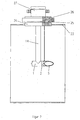
- the FIG. 1 shows the apparatus for detecting and reporting of fire phenomena in schematic representation and in section, wherein only a part of the shaft 14 is shown.
- the deflector 3 is connected directly to the reflector 9. Both parts are attached to the translucent ring 2.
- the translucent ring 2 is fastened on its other side to the tube of the displacement body 1 by means of screw thread.
- the other side of the displacement body 1 is closed by a closure cap 8, which is sealed and glued in the present case.
- Through the cap 8 of the adjusting insert 4 is introduced and secured.
- the adjusting insert 4 serves to adjust the concave mirror 6, which is mounted on a mirror mount 7.
- the cylindrical pin 12 and the adjusting screw 11, which constitutes a grub screw, make it possible to set the mirror 6 in two directions.
- the pivoting movement is achieved by adjusting the adjusting screw 5 relative to the spring 10, wherein the mirror 6 is rotated about the axis 13.
- Mirror 6 and reflector 9 are provided with a gold coating, which has good reflection properties and does not corrode even at higher temperatures.
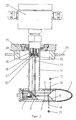
- FIG. 2 shows the said device within a tube, wherein the assembly into the tube wall 23 with the insert 24, the adapter 25 and the connection to the detector 26 takes place.
- a test emitter 18 is arranged, the signal 17 allows the inspection of the outside of the ring 2 for contamination.
- the FIG. 3 shows the device when detecting and reporting fire phenomena 15, from which emanates an electromagnetic radiation 16, is reflected by the reflector 9 via the mirror 6 to the end of the shaft 14 and reaches the transmitting and receiving part 19.
- the optical receiving unit 21 converts the received signal, passes it to the evaluation unit 27, z. As a detector, on and triggers an alarm if necessary.
- a transmitting diode 18 is arranged as test emitter 18, which emits a fundamental signal 17 via the light-conducting rod 20.
- the transmission takes place at regular intervals, for example every three seconds.
- This signal will hit the tip of the reflector 9 if the mirror 6 is correctly adjusted.
- the signal reflected back forms a measure of how transparent the ring 2 is.
- an "all around" deflection takes place on the ring 2, whereby the surface of the ring 2 "around” is monitored by 360 °. This is advantageous over a test from the outside, which only partially enters the ring 2 and tests the permeability only at the entrance surface.
- the signal received by the transmitting and receiving part 19 is conditioned by the electronics of the evaluation unit 27 and given a signal for replacing the ring 2 when a certain value is exceeded.
Landscapes
- Physics & Mathematics (AREA)
- General Physics & Mathematics (AREA)
- Business, Economics & Management (AREA)
- Emergency Management (AREA)
- Engineering & Computer Science (AREA)
- Computer Security & Cryptography (AREA)
- Chemical & Material Sciences (AREA)
- Analytical Chemistry (AREA)
- Investigating Or Analysing Materials By Optical Means (AREA)
- Instruments For Viewing The Inside Of Hollow Bodies (AREA)
- Fire-Detection Mechanisms (AREA)
- Fire Alarms (AREA)
Description
- Die Erfindung betrifft eine Vorrichtung entsprechend den Merkmalen des ersten Patentanspruches.
- Die Erfindung betrifft eine Einrichtung zum Erkennen von potentiellen Feuer- bzw. Zündquellen insbesondere heißen Partikeln bzw. Funken in Transporteinheiten für brennbare Stoffe. Solche Einrichtungen finden insbesondere Verwendung zur Überwachung des Inneren von Rohren und Kanälen, in denen ein brennbares, aus Stäuben, Flüssigkeiten oder Feststoffpartikeln bestehendes Transportgut in einer Fallstrecke oder mittels eines Förderluftstroms transportiert wird.
- Die Erfindung ist geeignet zum Einsatz in Förderleitungen, in denen leicht entzündliche oder explosive, vorzugsweise staubförmige Partikel pneumatisch transportiert werden.
- Um optische Feuererscheinungen in mit Feststoffpartikeln beladenen Förderleitungen zu detektieren und einen Alarm auszulösen, sind unterschiedliche Möglichkeiten bekannt. In den meisten Fällen wird eine optische Strahlung auf der Basis von UV- oder IR-Strahlung verwendet. Dazu sind Sensoren zur Branderkennung entweder in oder außerhalb der Wandung der Förderleitung angeordnet oder aber in einem Verdrängungskörper, der sich innerhalb des Gasstromes befindet. Diese werden besonders dann eingesetzt, wenn die Geschwindigkeit des Gasstromes und seine Beladung mit Feststoffpartikeln hoch sind, so daß eine Überwachung von der Rohrwand aus zu fehlerhaften Ergebnissen führt. Das gleiche gilt für Rohre mit relativ großem Durchmesser.
-
EP 1 422 675 A1 beschreibt eine Vorrichtung zur Entkopplung von staubbelasteten Anlagen mit Explosionsgefahr, bei der ein Sensor zum Erkennen von Veränderungen im explosionsgefährdeten Raum außerhalb eines Entkopplungsfensters angeordnet ist, der mit einer Auswerteelektronik und Löscheinheiten verbunden ist. Zur Branderkennung werden Sensoren verwendet, die im Infrarot-, UV- und im Bereich des sichtbaren Lichtes arbeiten. -
EP 1 413 998 B1 beschreibt eine Vorrichtung zum Erkennen von Glimmnestern in einer pneumatischen Förderleitung, bei der IR-Sensoren in einer langgestreckten Hülse angeordnet sind. Die IR-durchlässige Hülse ist mit zwei Befestigungen an einem in die Rohrleitung einsetzbaren Deckel angeordnet, wobei eine Aufnahmebuchse innerhalb der Hülse die IR-Sensoren trägt, wobei die Aufnahmebuchse aus zwei Teilen aufgebaut ist. Der Verdrängungskörper weist eine feste Anordnung gegenüber der Wandung der Förderleitung auf, besteht aus eine Vielzahl von Teilen und überträgt das durch die Sensoren im Inneren erfaßte Signal auf eine Alarmierungseinrichtung außerhalb des Verdrängungskörpers. Der/die IR-Sensoren ist/sind in radialer Richtung zur Transporteinrichtung angeordnet und mit einer transparenten Abdeckung gegenüber Verschmutzung oder Beschädigung geschützt. Nachteilig bei dieser Vorrichtung ist, daß der/die Sensoren in ihrem Temperatureinsatz sehr begrenzt sind. - Aus dem Dokument
DE 4304890 A1 ist eine ähnliche Vorrichtung wie beim DokumentEP 1 413 998 B1 zum Erkennen von heißen Teilen in einer pneumatischen Förderleitung bekannt. Der Unterschied ist, die IR-Sensoren nicht durch eine transparente Abdeckung gegenüber Verschmutzung oder Beschädigung geschützt ist/sind. Damit ist keine dauerhafte zuverlässige Erkennung potentiellen Feuer- bzw. Zündquellen möglich, da die Sensoren verschmutzen und die Gefahr einer Beschädigung durch den Förderstrom gegeben ist. - Aus dem Dokument
US 3,824,392 ist eine Vorrichtung zum Erkennen von heißen Teilen in einer pneumatischen Förderleitung bekannt, bei dem ein lichtintensiver Sensor mit einer kuppelförmigen lichtdurchlässigen Kalotte, zum Schutz des Sensors, an der Rohrwandung montiert ist. Nachteilig bei dieser Vorrichtung ist, dass die Kalotte stark zur Verschmutzung neigt, aufgrund der Form und weil im Bereich der Rohrwandung die Strömungsgeschwindigkeit gering ist. - Eine andere Einrichtung zum Melden von optischen Feuererscheinungen, insbesondere Funken, ist in
DE 29 16 086 B2 beschrieben. Diese Einrichtung weist ebenfalls einen Verdrängungskörper innerhalb der Förderleitung auf, wobei dieser aus zwei miteinander L-förmig verbundenen senkrecht zueinander stehenden Schenkeln besteht, deren erster Schenkel mit den Befestigungsmitteln verbunden ist und deren anderer Schenkel sich in Strömungsrichtung des Luftstromes erstreckt und eine Lichteintrittsfläche am freien Ende aufweist. In den Schenkel eintretende IR-Strahlung wird mittels strahlungsleitenden bogenförmig verlaufenden Fasern umgelenkt und einem Sensor zugeführt, der sich außerhalb der Rohrleitung befindet. Dieser Sensor ist mit einer geeigneten Auswerteelektronik gekoppelt, mit deren Hilfe ein Alarm auslösbar ist. Um einen Eintritt der Strahlung in den einen Schenkel der Vorrichtung zu realisieren, werden unterschiedliche Lösungen vorgeschlagen. Als Anwendungsbereich werden vor allem Förderströme für Holzbearbeitungsmaschinen genannt. - Die vorgeschlagenen Lösungen haben entweder den Nachteil, daß sie aus einer Vielzahl von Einzelteilen bestehen, daß der Lichtwellenleiter nach der Einkoppelung die übertragbare Strahlung mit starken Verlusten zum elektrischen Wandler leitet, daß der Verdrängungskörper gegen die Luftströmung gerichtet ist, aber nicht aerodynamisch geformt ist und somit die Optik verschmutzt, oder daß das optische Fenster nicht auf Verschmutzung überwacht ist und der Melder nicht auf Funktionsfähigkeit überwacht wird.
- Es ist daher Aufgabe der Erfindung, eine Vorrichtung zum Erkennen von Feuererscheinungen in Förderleitungen zu entwickeln, in denen Feststoffpartikel transportiert werden, die aerodynamisch geformt ist, eine Überwachung für Verschmutzung der Optik aufweist, eine sichere Übertragung der Daten aus dem Materialstrom der Förderleitung nach außen ermöglicht und eine verbesserte Funktionsfähigkeit aufweist.
- Diese Aufgabe wird durch eine Vorrichtung nach den Merkmalen des ersten Patentanspruches gelöst.
- Unteransprüche geben vorteilhafte Ausgestaltungen der Erfinder wieder.
- Die in der Förderleitung angeordnete Vorrichtung, bestehend aus einer optischen Erfassungseinheit, besteht aus einem transparenten zylindrischen Ring, aus optischen Reflexionsoberflächen, Justiereinheiten, statischen Elementen, um der optischen Erfassungseinheit Stabilität zu geben, optisch-elektrischem Wandler, elektronischer Auswerteeinheit, einer optischen Verschmutzungsüberwachung, die sich innerhalb oder außerhalb der zu überwachenden Rohren und Kanälen befinden kann, und einem Prallkörper, z. B. einem Abweiser, um den transparenten zylindrischen Ring vor Beschädigungen zu schützen.
- Die erfindungsgemäße Lösung sieht vor, daß der sich längs der Förderleitung erstreckende Verdrängungskörper auf einem Schaft angeordnet ist, der mit der Rohrwandung fest verbunden ist. Am einen Ende des Verdrängungskörpers ist ein aerodynamisch geformter Abweiser angeordnet, der strömungsmechanisch so gestaltet ist, daß er einen geringen Strömungswiderstand aufweist.
- Vorstellbar ist es auch, an beiden Enden des Verdrängungskörpers Abweiser anzuordnen. Das hat dann Vorteile, wenn der Materialstrom in der Förderleitung in unterschiedliche Richtungen fließt. Der Spiegel ist dann in etwa in der Mitte des Verdrängungskörpers so anzuordnen, daß er seine Umlenkfunktion erfüllt.
- Unmittelbar nach dem Abweiser ist ein lichtdurchlässiger Ring angeordnet, in dessen Inneren sich ein Reflektor befindet. Im Bedarfsfall kann der Ring mit einem speziellen Material beschichtet sein, der eine wellenlängenselektierte Detektion ermöglicht. Die Befestigung des lichtdurchlässigen Ringes kann mittels Gewinde, vorzugsweise einem metrischen Feingewinde, Preßpassung oder Verkleben erfolgen. Vorteilhaft ist ein Gewinde für eine rasche Montage und Austauschbarkeit. Der verwendete Reflektor ist rotationssymmetrisch ausgeführt und hat einen sehr hohen Reflexions-Wirkungsgrad. Im Verdrängungskörper ist ein verstellbarer Spiegel angeordnet. Dieser ist so anzuordnen, daß er die Strahlung ins Innere des Schaftes reflektiert. Ein Funke oder eine Zündquelle innerhalb des Partikelstroms, der mit dem Gasstrom innerhalb des Rohres befördert wird, sendet eine elektromagnetische oder optische Strahlung aus. Diese Strahlung gelangt durch den lichtdurchlässigen Ring zum Reflektor im Inneren des Verdrängungskörpers und wird von diesem über den verstellbaren Spiegel entlang des Schaftes zu einer optischen Empfangs- und Auswerteeinrichtung am Ende des Schaftes reflektiert.
- Vorteilhaft für die Beschichtung von Reflektor und Spiegel ist eine temperatur- und korrosionsbeständige Beschichtung mit hohem Reflexionsgrad. Als besonders vorteilhaft hat sich Gold als Beschichtungsmaterial erwiesen, zumal eine gute Reflexion im betrachteten Wellenlängenbereich erreicht wird.
- Der Spiegel, der vorzugsweise eine konkave Oberfläche aufweist, ist Bestandteil eines Justiereinsatzes, der leicht montierbar und auswechselbar ist. Mit Hilfe des Justiereinsatzes ist der Spiegel über eine Dreh- oder Schwenkachse des Spiegelhalters, eine Feder und Stelleinrichtungen so verstellbar, daß die elektromagnetische Strahlung des Funkens oder der Zündquelle exakt und konzentriert auf die optische Empfangs- und Auswerteeinheit am Ende des Schaftes gelenkt werden kann.
- Vorteilhaft ist es, daß der Justiereinsatz auswechselbar im Verdrängungskörper angeordnet ist. Dazu befindet sich eine Verschlußkappe, die verschraubbar ausgeführt sein kann, am Verdrängungskörper. Der Reflektor ist rotationssymmetrisch und kegelförmig ausgebildet. Seine Ausbildung kann kegelförmig konkav oder kegelförmig konvex sein, wodurch sich der effektive Sichtwinkel vergrößert oder verkleinert. Durch die konkave Ausgestaltung des Spiegels ist es möglich, die Strahlung gebündelt und konzentriert auf die optische Empfangs- und Auswerteeinheit zu lenken.
- Als Stelleinrichtungen für den Spiegel sind Justierschrauben, Stellschrauben, beispielsweise Madenschrauben oder Zylinderstifte vorgesehen, wobei diese mit einer Feder, beispielsweise einer Schraubenfeder, zusammenwirken. Statt dieser Ausführung ist aber auch eine Einstelleinrichtung mit Schrauben und Gegenschrauben oder mit Schrauben mit Zugfähigkeit als Stelleinrichtung für den Spiegel möglich.
- Das Ende des Schaftes führt durch die Rohrwandung nach außen zu einer Auswerteeinheit, beispielsweise zu einem Melder, in dem die Signalauswertung vorgenommen wird. Der Spiegel wird in X-, Y- und Z-Richtung so eingestellt, daß die elektromagnetische Strahlung in das Zentrum des optisch-elektrischen Wandlers am Ende des Schaftes trifft. Die Stelleinrichtung des Spiegels können Aktuatoren darstellen, die um den Spiegel angeordnet sind. Das können Piezoelemente sein. Die am Ende des Schaftes angeordnete Empfangseinheit leitet das gewandelte Signal an eine Auswerteeinheit, beispielsweise einen Melder, weiter. Dabei kann es sich um eine Leiterplatte zur Auswertung des Signals handeln.
- Am Schaft können Mittel angeordnet sein, mit denen der Schaft in Richtung auf die Achse des Förderrohres parallel zur Rohrwandung verstellbar ist. Andererseits kann der Schaft an einem Adapter angeordnet sind, der es erlaubt, den Schaft fest mit der Rohrwandung zu verbinden oder in diese einzusetzen.
- Um zu prüfen, ob der lichtdurchlässige Ring verschmutzt ist, besteht die Möglichkeit der Nutzung eines Testemitters, beispielsweise einer Sendediode. Diese kann für die Prüfung der Verschmutzung ein Signal in Richtung auf den lichtdurchlässigen Ring aussenden und das reflektierte Signal als Maß der Verschmutzung empfangen. Eine Prüfung von innen führt aber nicht dazu, daß eine Verschmutzung durch dunkle Partikel auf der Außenseite des Ringes einwandfrei erkannt werden. Deshalb ist es vorteilhaft, auch eine Prüfung der Verschmutzung durch einen Testemitter von außen durchzuführen, der beispielsweise an der Rohrwand montiert ist. Beide Möglichkeiten können einzeln oder in Kombination angewandt werden. Das Aussenden des Signals kann kontinulerlich oder im Takt, zwischen einer und zehn Sekunden, erfolgen. Das zurückfließende Signal wird ausgewertet. Sobald festgestellt wird, daß der lichtdurchlässige Ring über ein bestimmtes Maß verschmutzt ist, kann durch die Auswerteeinheit ein betreffendes Signal zum Reinigen oder zum Wechseln des lichtdurchlässigen Ringes erfolgen. Bei richtiger Justage fällt das Signal auf die Spitze des Reflektors, wodurch die Fläche des Ringes rundum, d. h. um 360 Grad überwacht wird. Die Überwachung erfolgt mit einem einzigen Detektor. Das ist besonders vorteilhaft gegenüber Tests von außen, bei denen ein Strahl nur partiell in den Ring eintritt, wodurch nur die Durchlässigkeit an der Eintrittsfläche getestet wird.
- Es ist weiterhin vorteilhaft, den internen Test zur Spiegeljustage über die am Spiegel angeordneten Aktuatoren durchzuführen, zu deren Verstellen man aus den Testantworten eine Regelgröße regeneriert, wodurch eine automatische optische Justage des Spiegels, beispielsweise im Lernmodus, möglich ist.
- Vorteilhaft ist es, den lichtdurchlässigen Ring aus Glas, Quarz, Kunststoff oder Saphir auszuführen. Weiterhin ist es vorteilhaft, den Abweiser mit glatter Oberfläche als Stahlhülse mit einer Gummi-, Teflon- oder Halarbeschichtung auszubilden, wobei der Reflektor auf der Gegenseite angeordnet ist und beide Teile baulich eine Einheit bilden können. Dabei ist es vorteilhaft, Reflektor und Abweiser direkt auf den lichtdurchlässigen Ring in Form einer Preßpassung aufzustecken.
- Vorteilhaft ist es weiterhin, vor der optischen Sende- und Empfangseinheit, z. B. am Ende des Schaftes, einen Schutzfilter anzuordnen. Das kann beispielsweise ein optisch durchlässiges Glasteil sein. Weiterhin ist es vorteilhaft, wenn der optische Signalgeber einen Testemitter, beispielsweise eine Sendediode mit einem Lichtleitstab, darstellt. Ein Lichtstab hat den Vorteil, daß eine bestimmte Abstrahlcharakteristik vorhanden ist, die bei Punktförmigkeit die Spiegeljustage erleichtert. An den Schutzfilter kann ein Lichtleitbündel positioniert werden, um die Auswerteeinheit, z. B. den Melder, abzusetzen und vor hohen Temperaturen zu schützen. Das ist dann vorteilhaft, wenn die Elektronik nur für bestimmte Temperaturen, z. B. bis 80 °C, einsetzbar und eine thermische Entkopplung erforderlich ist.
- Die erfindungsgemäße Vorrichtung hat den Vorteil, daß sie aus wenigen Teilen besteht und somit kostengünstig herstellbar ist, die empfangenen Signale zuverlässig zu einem Melder oder einer Auswerteeinheit gelangen und jederzeit eine Information vorhanden ist, wie lichtdurchlässig das optische Fenster ist, so daß dieses schnell und unkompliziert ausgewechselt werden kann.
- Weiterhln ist es vorteilhaft, daß durch einen Strahlungsempfänger im Zusammenhang mit der Vorrichtung zum Melden ein Winkel von 360 Grad mittels Detektor überwacht wird, also für eine Rundum-Überwachung nur eine einzige Auswerteeinheit erforderlich ist.
- Im Folgenden wird die Erfindung an einem Ausführungsbeispiel und drei Figuren näher erläutert. Die Figuren zeigen:
- Figur 1:
- Vorrichtung zum Erfassen und Melden von Feuererscheinungen in Prinzipdarstellung und Schnitt.
- Figur 2:
- Vorrichtung aus
Figur 1 innerhalb einer Förderleitung mit IR-Sender und -empfänger mit Zusammenhang mit der Förderleitung. - Figur 3:
- Vorrichtung zum Erfassen und Melden von optischen Feuererscheinungen mit Überwachungseinrichtung für das optische Fenster.
- Die
Figur 1 zeigt die Vorrichtung zum Erfassen und Melden von Feuererscheinungen in Prinzipdarstellung und im Schnitt, wobei nur ein Teil des Schaftes 14 gezeigt ist. Der Abweiser 3 ist unmittelbar mit dem Reflektor 9 verbunden. Beide Teile sind am lichtdurchlässigen Ring 2 befestigt. Der lichtdurchlässige Ring 2 ist auf seiner anderen Seite am Rohr des Verdrängungskörpers 1 mittels Schraubgewinde befestigt. Die andere Seite des Verdrängungskörpers 1 ist durch eine Verschlußkappe 8 verschlossen, die abdichtend und im vorliegenden Fall aufgeklebt ist. Durch die Verschlußkappe 8 wird der Justiereinsatz 4 eingebracht und befestigt. Der Justiereinsatz 4 dient dazu, den konkaven Spiegel 6 zu justieren, der auf einer Spiegelhalterung 7 befestigt ist. Der Zylinderstift 12 und die Stellschraube 11, die eine Madenschraube darstellt, erlauben es, den Spiegel 6 in zwei Richtungen einzustellen. Die Schwenkbewegung wird durch Verstellen der Justierschraube 5 gegenüber der Feder 10 erreicht, wobei der Spiegel 6 um die Achse 13 gedreht wird. Damit besteht nach Einbau die Möglichkeit einer exakten Justierung des Spiegels 6 in X-, Y- und Z-Richtung. Spiegel 6 und Reflektor 9 sind mit einer Goldbeschichtung versehen, die gute Reflexionseigenschaften aufweist und auch bei höheren Temperaturen nicht korrodiert. - Die
Figur 2 zeigt die genannte Vorrichtung innerhalb eines Rohres, wobei die Montage in die Rohrwandung 23 mit dem Einsatz 24, dem Adapter 25 und der Verbindung zum Melder 26 erfolgt. Die Auswerteeinheit 27, ein Melder, ist außerhalb des Rohres angeordnet, wobei der Schaft 14 ins Rohrinnere führt. An der Auswerteeinheit 27 ist ein Testemitter 18 angeordnet, dessen Signal 17 die Überprüfung der Außenseite des Ringes 2 auf Verschmutzung ermöglicht. - Die
Figur 3 zeigt die Vorrichtung beim Erfassen und Melden von Feuererscheinungen 15, von denen eine elektromagnetische Strahlung 16 ausgeht, vom Reflektor 9 über den Spiegel 6 zum Ende des Schaftes 14 reflektiert wird und zum Sende- und Empfangsteil 19 gelangt. Die optische Empfangseinheit 21 wandelt das erhaltene Signal, leitet es an die Auswerteeinheit 27, z. B. einen Melder, weiter und löst gegebenenfalls einen Alarm aus. - Zum Prüfen des Verschmutzungsgrades des lichtdurchlässigen Ringes 2 ist als Testemitter 18 eine Sendediode angeordnet, die ein Grundsignal 17 über den Lichtleitstab 20 aussendet. Das Aussenden erfolgt in regelmäßigen Abständen, beispielsweise alle drei Sekunden. Dieses Signal trifft bei richtiger Einstellung des Spiegels 6 auf die Spitze des Reflektors 9. Das zurückreflektierte Signal bildet ein Maß dafür, wie lichtdurchlässig der Ring 2 ist. Bei richtiger Justage auf die Spitze des Reflektors 9 erfolgt eine "rundherum" Ablenkung auf den Ring 2, wodurch die Fläche des Ringes 2 "rundherum" um 360° überwacht wird. Das ist vorteilhaft gegenüber einem Test von außen, der nur partiell in den Ring 2 eintritt und die Durchlässigkeit nur an der Eintrittsfläche testet. Das vom Sende- und Empfangsteil 19 empfangene Signal wird von der Elektronik der Auswerteeinheit 27 aufbereitet und bei Überschreiten eines bestimmten Wertes ein Signal zum Auswechseln des Ringes 2 gegeben.
Claims (16)
- Vorrichtung zum Erkennen und Melden von Feuererscheinungen, insbesondere Funken (15) in einem gegebenenfalls mit Feststoffpartikeln beladenen, eine Förderleitung durchströmenden Gasstrom mittels eines in Strömungsrichtung der Förderleitung längs erstreckten Verdrängungskörpers, bestehend aus- dem auf einem Schaft (14) angeordneten Verdrängungskörper (1)- mindestens einem an einem Ende des Verdrängungskörpers (1) angeordneten Abweiser (3) vor einem lichtdurchlässigen Ring (2), in dessen Inneren ein Reflektor (9) angeordnet ist,- einem verstellbaren Spiegel (6) im Inneren des Verdrängungskörpers (1) über dem eine elektromagnetische Strahlung (16) in das Innere des Schaftes (14) reflektiert wird und- einer optischen Empfangs- (21) und Auswerteeinheit (27) am Ende des Schaftes gekennzeichnet dadurch, daß ein Grundsignal (17) über den Spiegel (6) und die Spitze des Reflektors (9) auf den lichtdurchlässigen Ring (2) geleitet wird, wodurch dieser um 360 Grad auf Lichtdurchlässigkeit als Maß der Verschmutzung überwacht wird.
- Vorrichtung nach Anspruch 1, dadurch gekennzeichnet, daß der Spiegel (6) Bestandteil eines Justiereinsatzes (4) darstellt, der aus einer Dreh- oder Schwenkachse (13), einem Spiegelhalter (7), einer Feder (10) und Stelleinrichtungen (5, 10, 11, 12) besteht.
- Vorrichtung nach Anspruch 2, dadurch gekennzeichnet, daß der Justiereinsatz (4) auswechselbar befestigt ist.
- Vorrichtung nach den Ansprüchen 1 bis 3, dadurch gekennzeichnet, daß der Spiegel (6) konkav und um die Achse (13) mittels Stelleinrichtungen (5, 10, 11, 12) verstellbar ist.
- Vorrichtung nach den Ansprüchen 1 bis 4, dadurch gekennzeichnet, daß der Reflektor (9) kegelförmig, kegelförmig konkav oder kegelförmig konvex ausgebildet ist.
- Vorrichtung nach den Ansprüchen 1 bis 5, dadurch gekennzeichnet, daß am Ende des Schaftes (14) ein optischer Signalgeber angeordnet ist.
- Vorrichtung nach den Ansprüchen 1 bis 6, dadurch gekennzeichnet, daß der optische Signalgeber eine Sendediode (18) mit einem Lichtleitstab (20) darstellt.
- Vorrichtung nach den Ansprüchen 1 bis 7, dadurch gekennzeichnet, daß vor der optischen Empfangseinheit (21) ein Schutzfilter (22) angeordnet ist.
- Vorrichtung nach den Ansprüchen 1 bis 8, dadurch gekennzeichnet, daß am Schaft (14) Verstelleinrichtungen (25) zum Verstellen des Schaftes (14) angeordnet sind.
- Vorrichtung nach den Ansprüchen 1 bis 9, dadurch gekennzeichnet, daß der lichtdurchlässige Ring (2) aus Glas, Quarz, Kunststoff oder Saphir besteht und mit seinen Anschlußteilen (3, 1) verschraubt ist.
- Vorrichtung nach den Ansprüchen 1 bis 10, dadurch gekennzeichnet, daß das der Abweiser (3) als Stahlhülse mit glatter Oberfläche ausgebildet ist, auf deren anderer Seite der lichtdurchlässige Ring (2) und der Reflektor (9) angeordnet sind.
- Vorrichtung nach den Ansprüchen 1 bis 11, dadurch gekennzeichnet, daß der Abweiser (3) mit einer anhaftungsverhindernden Oberfläche wie einer Gummi-, Teflon- oder Halarbeschichtung ausgeführt ist.
- Vorrichtung nach den Ansprüchen 1 bis 12, dadurch gekennzeichnet, daß zur Justage des Spiegels (6) Aktuatoren angeordnet sind.
- Vorrichtung nach den Ansprüchen 1 bis 13, dadurch gekennzeichnet, daß außerhalb oder in der Rohrwandung (23) ein Testemitter (18) angeordnet ist.
- Vorrichtung nach Anspruch 14, dadurch gekennzeichnet, daß der Testemitter (18) an der Auswerteeinheit (27) angeordnet ist.
- Vorrichtung nach den Ansprüchen 1 bis 15, dadurch gekennzeichnet, daß der Reflektor (9) und der Spiegel (6) für die Reflexion mit Gold beschichtet sind.
Priority Applications (5)
| Application Number | Priority Date | Filing Date | Title |
|---|---|---|---|
| EP09005581A EP2244237B1 (de) | 2009-04-21 | 2009-04-21 | Vorrichtung zum Erkennen und Melden von Feuererscheinungen mit brennbaren Materialen |
| RU2010115742/08A RU2010115742A (ru) | 2009-04-21 | 2010-04-20 | Устройство для распознания и сигнализации появления огня в горючих материалах |
| US12/799,187 US20100265510A1 (en) | 2009-04-21 | 2010-04-20 | Device for recognizing and reporting fire phenomena with combustible materials |
| CN201010167068A CN101872528A (zh) | 2009-04-21 | 2010-04-20 | 用于对带有可燃材料的火情进行识别和报警的设备 |
| CA2701242A CA2701242A1 (en) | 2009-04-21 | 2010-04-20 | Device for recognizing and reporting fire phenomena with combustible materials |
Applications Claiming Priority (1)
| Application Number | Priority Date | Filing Date | Title |
|---|---|---|---|
| EP09005581A EP2244237B1 (de) | 2009-04-21 | 2009-04-21 | Vorrichtung zum Erkennen und Melden von Feuererscheinungen mit brennbaren Materialen |
Publications (2)
| Publication Number | Publication Date |
|---|---|
| EP2244237A1 EP2244237A1 (de) | 2010-10-27 |
| EP2244237B1 true EP2244237B1 (de) | 2012-07-04 |
Family
ID=41090294
Family Applications (1)
| Application Number | Title | Priority Date | Filing Date |
|---|---|---|---|
| EP09005581A Not-in-force EP2244237B1 (de) | 2009-04-21 | 2009-04-21 | Vorrichtung zum Erkennen und Melden von Feuererscheinungen mit brennbaren Materialen |
Country Status (5)
| Country | Link |
|---|---|
| US (1) | US20100265510A1 (de) |
| EP (1) | EP2244237B1 (de) |
| CN (1) | CN101872528A (de) |
| CA (1) | CA2701242A1 (de) |
| RU (1) | RU2010115742A (de) |
Families Citing this family (3)
| Publication number | Priority date | Publication date | Assignee | Title |
|---|---|---|---|---|
| CN103400472B (zh) * | 2013-08-16 | 2015-11-25 | 泉州宏讯电子有限公司 | 具有开窗装置的新型警报仪 |
| CN107583224B (zh) * | 2017-09-19 | 2020-04-24 | 中海石油技术检测有限公司 | 海上石油火气系统检测评估实验平台及方法 |
| CN108615327A (zh) * | 2018-06-11 | 2018-10-02 | 广州市景彤机电设备有限公司 | 移动端可视化监控管道火花方法与移动终端 |
Family Cites Families (10)
| Publication number | Priority date | Publication date | Assignee | Title |
|---|---|---|---|---|
| SE364588B (de) | 1972-04-24 | 1974-02-25 | Pak Construction Ab | |
| US3927555A (en) * | 1973-10-15 | 1975-12-23 | Gen Electric | Hydrogen detector system |
| DE2916086C3 (de) * | 1979-04-20 | 1981-10-22 | Preussag Ag Feuerschutz, 2060 Bad Oldesloe | Einrichtung zum Melden von optischen Feuererscheinungen, insbesondere Funken |
| DE3017144C2 (de) * | 1980-05-05 | 1984-09-27 | Preussag Ag Feuerschutz, 2060 Bad Oldesloe | Einrichtung zu Melden von optischen Feuererscheinungen, insbesondere Funken |
| US4547673A (en) * | 1983-01-10 | 1985-10-15 | Detector Electronics Corporation | Smoke and flame detector |
| CH684552A5 (de) | 1992-04-27 | 1994-10-14 | Jossi Hans Praezisionsmechanik | Verfahren und Vorrichtung zum Ermitteln einer Messgrösse aus einem in einer Rohrleitung strömenden Medium. |
| JP2002223019A (ja) * | 2001-01-24 | 2002-08-09 | Rion Co Ltd | レーザ発振器とそれを用いた光散乱式粒子検出器 |
| DE10249743A1 (de) | 2002-10-25 | 2004-05-06 | Forschungsgesellschaft für angewandte Systemsicherheit und Arbeitsmedizin e.V. | Vorrichtung zum Erkennen von Glimmnestern |
| DE20218136U1 (de) | 2002-11-21 | 2003-03-06 | Minimax Gmbh, 23843 Bad Oldesloe | Funkenlöschanlage für bewegte staubförmige Partikel |
| AR062764A1 (es) * | 2006-11-06 | 2008-12-03 | Victaulic Co Of America | Metodo y aparato para secar redes de canerias equipadas con rociadores |
-
2009
- 2009-04-21 EP EP09005581A patent/EP2244237B1/de not_active Not-in-force
-
2010
- 2010-04-20 CA CA2701242A patent/CA2701242A1/en not_active Abandoned
- 2010-04-20 RU RU2010115742/08A patent/RU2010115742A/ru not_active Application Discontinuation
- 2010-04-20 US US12/799,187 patent/US20100265510A1/en not_active Abandoned
- 2010-04-20 CN CN201010167068A patent/CN101872528A/zh active Pending
Also Published As
| Publication number | Publication date |
|---|---|
| CN101872528A (zh) | 2010-10-27 |
| RU2010115742A (ru) | 2011-10-27 |
| CA2701242A1 (en) | 2010-10-21 |
| EP2244237A1 (de) | 2010-10-27 |
| US20100265510A1 (en) | 2010-10-21 |
Similar Documents
| Publication | Publication Date | Title |
|---|---|---|
| EP2251846B1 (de) | Flammenmelder | |
| DE102016216074A1 (de) | Vorrichtung zum gleichzeitigen Messen der Innentemperatur und des Feinstaubs in einem Fahrzeug | |
| EP2356432A1 (de) | Sensoranordnung | |
| DE102010022159A1 (de) | Optischer Sensor | |
| DE102014000210B3 (de) | Modifizierte Messküvette | |
| EP2244237B1 (de) | Vorrichtung zum Erkennen und Melden von Feuererscheinungen mit brennbaren Materialen | |
| DE102008050109A1 (de) | Optischer Sensor | |
| DE102012007864B4 (de) | Trübungssensor sowie Durchflusszähler für Fluid | |
| DE2833635C2 (de) | Verfahren zur Messung der Verschmutzung von optischen Grenzflächen bei optischen Empfängern und Einrichtung zur Durchführung des Verfahrens | |
| DE202007004364U1 (de) | Sensoranordnung | |
| DE102015110393B4 (de) | Rauchmelder mit Infrarot-Lichtring-Abdecküberwachung | |
| DE102017005386A1 (de) | Überwachungsverfahren | |
| DE102014000073B4 (de) | Sensorvorrichtung, insbesondere zur Erfassung von Umgebungsbedingungen eines Kraftfahrzeuges | |
| DE102015110865A1 (de) | Trennvorrichtung und Verfahren zum Detektieren einer Stoffansammlung in einer solchen Trennvorrichtung | |
| DE1957494C3 (de) | Lichtelektrische Abtastvorrichtung | |
| DE3017144C2 (de) | Einrichtung zu Melden von optischen Feuererscheinungen, insbesondere Funken | |
| DE102019203230A1 (de) | Sensorvorrichtung umfassend ein Sensorelement und eine Abschlussscheibe | |
| EP3662238A1 (de) | Optische detektorvorrichtung | |
| EP1331475B1 (de) | Verfahren und Vorrichtung zum Messen der Grössenverteilung und Konzentration von Partikeln in einem Fluid | |
| EP2908297B1 (de) | Linearbrandmelder sowie Verfahren zum Betreiben des Linearbrandmelders | |
| EP2737299A1 (de) | Vorrichtung und verfahren zur messung der partikelkonzentration in einem aerosol | |
| DE10011581C2 (de) | Einrichtung zur Registrierung fliegender Feststoffpartikel | |
| DE202005014771U1 (de) | Einrichtung zum Erfassen und Melden von optischen Feuererscheinungen für bewegte staubförmige Partikel | |
| EP2631669A1 (de) | Optische Einrichtung | |
| DE10204906A1 (de) | Optische Sensoranordnung zur Detektion von Aerosolen |
Legal Events
| Date | Code | Title | Description |
|---|---|---|---|
| PUAI | Public reference made under article 153(3) epc to a published international application that has entered the european phase |
Free format text: ORIGINAL CODE: 0009012 |
|
| AK | Designated contracting states |
Kind code of ref document: A1 Designated state(s): AT BE BG CH CY CZ DE DK EE ES FI FR GB GR HR HU IE IS IT LI LT LU LV MC MK MT NL NO PL PT RO SE SI SK TR |
|
| AX | Request for extension of the european patent |
Extension state: AL BA RS |
|
| 17P | Request for examination filed |
Effective date: 20110419 |
|
| 17Q | First examination report despatched |
Effective date: 20110825 |
|
| GRAC | Information related to communication of intention to grant a patent modified |
Free format text: ORIGINAL CODE: EPIDOSCIGR1 |
|
| GRAP | Despatch of communication of intention to grant a patent |
Free format text: ORIGINAL CODE: EPIDOSNIGR1 |
|
| GRAS | Grant fee paid |
Free format text: ORIGINAL CODE: EPIDOSNIGR3 |
|
| GRAA | (expected) grant |
Free format text: ORIGINAL CODE: 0009210 |
|
| AK | Designated contracting states |
Kind code of ref document: B1 Designated state(s): AT BE BG CH CY CZ DE DK EE ES FI FR GB GR HR HU IE IS IT LI LT LU LV MC MK MT NL NO PL PT RO SE SI SK TR |
|
| REG | Reference to a national code |
Ref country code: GB Ref legal event code: FG4D Free format text: NOT ENGLISH |
|
| REG | Reference to a national code |
Ref country code: CH Ref legal event code: EP |
|
| REG | Reference to a national code |
Ref country code: AT Ref legal event code: REF Ref document number: 565416 Country of ref document: AT Kind code of ref document: T Effective date: 20120715 |
|
| REG | Reference to a national code |
Ref country code: IE Ref legal event code: FG4D Free format text: LANGUAGE OF EP DOCUMENT: GERMAN |
|
| REG | Reference to a national code |
Ref country code: DE Ref legal event code: R096 Ref document number: 502009003963 Country of ref document: DE Effective date: 20120830 |
|
| REG | Reference to a national code |
Ref country code: SE Ref legal event code: TRGR |
|
| REG | Reference to a national code |
Ref country code: NL Ref legal event code: VDEP Effective date: 20120704 |
|
| PG25 | Lapsed in a contracting state [announced via postgrant information from national office to epo] |
Ref country code: SI Free format text: LAPSE BECAUSE OF FAILURE TO SUBMIT A TRANSLATION OF THE DESCRIPTION OR TO PAY THE FEE WITHIN THE PRESCRIBED TIME-LIMIT Effective date: 20120704 |
|
| REG | Reference to a national code |
Ref country code: LT Ref legal event code: MG4D Effective date: 20120704 |
|
| PG25 | Lapsed in a contracting state [announced via postgrant information from national office to epo] |
Ref country code: LT Free format text: LAPSE BECAUSE OF FAILURE TO SUBMIT A TRANSLATION OF THE DESCRIPTION OR TO PAY THE FEE WITHIN THE PRESCRIBED TIME-LIMIT Effective date: 20120704 Ref country code: HR Free format text: LAPSE BECAUSE OF FAILURE TO SUBMIT A TRANSLATION OF THE DESCRIPTION OR TO PAY THE FEE WITHIN THE PRESCRIBED TIME-LIMIT Effective date: 20120704 Ref country code: CY Free format text: LAPSE BECAUSE OF FAILURE TO SUBMIT A TRANSLATION OF THE DESCRIPTION OR TO PAY THE FEE WITHIN THE PRESCRIBED TIME-LIMIT Effective date: 20120704 Ref country code: NO Free format text: LAPSE BECAUSE OF FAILURE TO SUBMIT A TRANSLATION OF THE DESCRIPTION OR TO PAY THE FEE WITHIN THE PRESCRIBED TIME-LIMIT Effective date: 20121004 Ref country code: FI Free format text: LAPSE BECAUSE OF FAILURE TO SUBMIT A TRANSLATION OF THE DESCRIPTION OR TO PAY THE FEE WITHIN THE PRESCRIBED TIME-LIMIT Effective date: 20120704 Ref country code: IS Free format text: LAPSE BECAUSE OF FAILURE TO SUBMIT A TRANSLATION OF THE DESCRIPTION OR TO PAY THE FEE WITHIN THE PRESCRIBED TIME-LIMIT Effective date: 20121104 |
|
| PG25 | Lapsed in a contracting state [announced via postgrant information from national office to epo] |
Ref country code: PL Free format text: LAPSE BECAUSE OF FAILURE TO SUBMIT A TRANSLATION OF THE DESCRIPTION OR TO PAY THE FEE WITHIN THE PRESCRIBED TIME-LIMIT Effective date: 20120704 Ref country code: PT Free format text: LAPSE BECAUSE OF FAILURE TO SUBMIT A TRANSLATION OF THE DESCRIPTION OR TO PAY THE FEE WITHIN THE PRESCRIBED TIME-LIMIT Effective date: 20121105 Ref country code: GR Free format text: LAPSE BECAUSE OF FAILURE TO SUBMIT A TRANSLATION OF THE DESCRIPTION OR TO PAY THE FEE WITHIN THE PRESCRIBED TIME-LIMIT Effective date: 20121005 Ref country code: LV Free format text: LAPSE BECAUSE OF FAILURE TO SUBMIT A TRANSLATION OF THE DESCRIPTION OR TO PAY THE FEE WITHIN THE PRESCRIBED TIME-LIMIT Effective date: 20120704 |
|
| PG25 | Lapsed in a contracting state [announced via postgrant information from national office to epo] |
Ref country code: NL Free format text: LAPSE BECAUSE OF FAILURE TO SUBMIT A TRANSLATION OF THE DESCRIPTION OR TO PAY THE FEE WITHIN THE PRESCRIBED TIME-LIMIT Effective date: 20120704 |
|
| PG25 | Lapsed in a contracting state [announced via postgrant information from national office to epo] |
Ref country code: RO Free format text: LAPSE BECAUSE OF FAILURE TO SUBMIT A TRANSLATION OF THE DESCRIPTION OR TO PAY THE FEE WITHIN THE PRESCRIBED TIME-LIMIT Effective date: 20120704 Ref country code: ES Free format text: LAPSE BECAUSE OF FAILURE TO SUBMIT A TRANSLATION OF THE DESCRIPTION OR TO PAY THE FEE WITHIN THE PRESCRIBED TIME-LIMIT Effective date: 20121015 Ref country code: DK Free format text: LAPSE BECAUSE OF FAILURE TO SUBMIT A TRANSLATION OF THE DESCRIPTION OR TO PAY THE FEE WITHIN THE PRESCRIBED TIME-LIMIT Effective date: 20120704 Ref country code: EE Free format text: LAPSE BECAUSE OF FAILURE TO SUBMIT A TRANSLATION OF THE DESCRIPTION OR TO PAY THE FEE WITHIN THE PRESCRIBED TIME-LIMIT Effective date: 20120704 Ref country code: CZ Free format text: LAPSE BECAUSE OF FAILURE TO SUBMIT A TRANSLATION OF THE DESCRIPTION OR TO PAY THE FEE WITHIN THE PRESCRIBED TIME-LIMIT Effective date: 20120704 |
|
| PLBE | No opposition filed within time limit |
Free format text: ORIGINAL CODE: 0009261 |
|
| STAA | Information on the status of an ep patent application or granted ep patent |
Free format text: STATUS: NO OPPOSITION FILED WITHIN TIME LIMIT |
|
| PG25 | Lapsed in a contracting state [announced via postgrant information from national office to epo] |
Ref country code: IT Free format text: LAPSE BECAUSE OF FAILURE TO SUBMIT A TRANSLATION OF THE DESCRIPTION OR TO PAY THE FEE WITHIN THE PRESCRIBED TIME-LIMIT Effective date: 20120704 Ref country code: SK Free format text: LAPSE BECAUSE OF FAILURE TO SUBMIT A TRANSLATION OF THE DESCRIPTION OR TO PAY THE FEE WITHIN THE PRESCRIBED TIME-LIMIT Effective date: 20120704 |
|
| 26N | No opposition filed |
Effective date: 20130405 |
|
| PG25 | Lapsed in a contracting state [announced via postgrant information from national office to epo] |
Ref country code: BG Free format text: LAPSE BECAUSE OF FAILURE TO SUBMIT A TRANSLATION OF THE DESCRIPTION OR TO PAY THE FEE WITHIN THE PRESCRIBED TIME-LIMIT Effective date: 20121004 |
|
| REG | Reference to a national code |
Ref country code: DE Ref legal event code: R097 Ref document number: 502009003963 Country of ref document: DE Effective date: 20130405 |
|
| BERE | Be: lapsed |
Owner name: MINIMAX G.M.B.H. & CO KG Effective date: 20130430 |
|
| PG25 | Lapsed in a contracting state [announced via postgrant information from national office to epo] |
Ref country code: MC Free format text: LAPSE BECAUSE OF FAILURE TO SUBMIT A TRANSLATION OF THE DESCRIPTION OR TO PAY THE FEE WITHIN THE PRESCRIBED TIME-LIMIT Effective date: 20120704 |
|
| REG | Reference to a national code |
Ref country code: CH Ref legal event code: PL |
|
| GBPC | Gb: european patent ceased through non-payment of renewal fee |
Effective date: 20130421 |
|
| REG | Reference to a national code |
Ref country code: IE Ref legal event code: MM4A |
|
| PG25 | Lapsed in a contracting state [announced via postgrant information from national office to epo] |
Ref country code: CH Free format text: LAPSE BECAUSE OF NON-PAYMENT OF DUE FEES Effective date: 20130430 Ref country code: GB Free format text: LAPSE BECAUSE OF NON-PAYMENT OF DUE FEES Effective date: 20130421 Ref country code: BE Free format text: LAPSE BECAUSE OF NON-PAYMENT OF DUE FEES Effective date: 20130430 Ref country code: LI Free format text: LAPSE BECAUSE OF NON-PAYMENT OF DUE FEES Effective date: 20130430 |
|
| REG | Reference to a national code |
Ref country code: FR Ref legal event code: ST Effective date: 20131231 |
|
| PG25 | Lapsed in a contracting state [announced via postgrant information from national office to epo] |
Ref country code: FR Free format text: LAPSE BECAUSE OF NON-PAYMENT OF DUE FEES Effective date: 20130430 |
|
| PG25 | Lapsed in a contracting state [announced via postgrant information from national office to epo] |
Ref country code: IE Free format text: LAPSE BECAUSE OF NON-PAYMENT OF DUE FEES Effective date: 20130421 |
|
| REG | Reference to a national code |
Ref country code: DE Ref legal event code: R082 Ref document number: 502009003963 Country of ref document: DE |
|
| PG25 | Lapsed in a contracting state [announced via postgrant information from national office to epo] |
Ref country code: MT Free format text: LAPSE BECAUSE OF FAILURE TO SUBMIT A TRANSLATION OF THE DESCRIPTION OR TO PAY THE FEE WITHIN THE PRESCRIBED TIME-LIMIT Effective date: 20120704 |
|
| REG | Reference to a national code |
Ref country code: AT Ref legal event code: MM01 Ref document number: 565416 Country of ref document: AT Kind code of ref document: T Effective date: 20140421 |
|
| PG25 | Lapsed in a contracting state [announced via postgrant information from national office to epo] |
Ref country code: TR Free format text: LAPSE BECAUSE OF FAILURE TO SUBMIT A TRANSLATION OF THE DESCRIPTION OR TO PAY THE FEE WITHIN THE PRESCRIBED TIME-LIMIT Effective date: 20120704 |
|
| PG25 | Lapsed in a contracting state [announced via postgrant information from national office to epo] |
Ref country code: HU Free format text: LAPSE BECAUSE OF FAILURE TO SUBMIT A TRANSLATION OF THE DESCRIPTION OR TO PAY THE FEE WITHIN THE PRESCRIBED TIME-LIMIT; INVALID AB INITIO Effective date: 20090421 Ref country code: LU Free format text: LAPSE BECAUSE OF NON-PAYMENT OF DUE FEES Effective date: 20130421 Ref country code: MK Free format text: LAPSE BECAUSE OF FAILURE TO SUBMIT A TRANSLATION OF THE DESCRIPTION OR TO PAY THE FEE WITHIN THE PRESCRIBED TIME-LIMIT Effective date: 20120704 |
|
| PG25 | Lapsed in a contracting state [announced via postgrant information from national office to epo] |
Ref country code: AT Free format text: LAPSE BECAUSE OF NON-PAYMENT OF DUE FEES Effective date: 20140421 |
|
| PGFP | Annual fee paid to national office [announced via postgrant information from national office to epo] |
Ref country code: SE Payment date: 20190425 Year of fee payment: 11 |
|
| PG25 | Lapsed in a contracting state [announced via postgrant information from national office to epo] |
Ref country code: SE Free format text: LAPSE BECAUSE OF NON-PAYMENT OF DUE FEES Effective date: 20200422 |
|
| REG | Reference to a national code |
Ref country code: DE Ref legal event code: R081 Ref document number: 502009003963 Country of ref document: DE Owner name: MINIMAX GMBH, DE Free format text: FORMER OWNER: MINIMAX GMBH & CO. KG, 23843 BAD OLDESLOE, DE |
|
| PGFP | Annual fee paid to national office [announced via postgrant information from national office to epo] |
Ref country code: DE Payment date: 20220419 Year of fee payment: 14 |
|
| REG | Reference to a national code |
Ref country code: DE Ref legal event code: R119 Ref document number: 502009003963 Country of ref document: DE |
|
| PG25 | Lapsed in a contracting state [announced via postgrant information from national office to epo] |
Ref country code: DE Free format text: LAPSE BECAUSE OF NON-PAYMENT OF DUE FEES Effective date: 20231103 |