EP2244231B1 - Vorrichtung zur Überwachung von Strukturen - Google Patents
Vorrichtung zur Überwachung von Strukturen Download PDFInfo
- Publication number
- EP2244231B1 EP2244231B1 EP09425154.3A EP09425154A EP2244231B1 EP 2244231 B1 EP2244231 B1 EP 2244231B1 EP 09425154 A EP09425154 A EP 09425154A EP 2244231 B1 EP2244231 B1 EP 2244231B1
- Authority
- EP
- European Patent Office
- Prior art keywords
- data
- structures
- identification
- register
- reading device
- Prior art date
- Legal status (The legal status is an assumption and is not a legal conclusion. Google has not performed a legal analysis and makes no representation as to the accuracy of the status listed.)
- Not-in-force
Links
Images


Classifications
-
- G—PHYSICS
- G07—CHECKING-DEVICES
- G07C—TIME OR ATTENDANCE REGISTERS; REGISTERING OR INDICATING THE WORKING OF MACHINES; GENERATING RANDOM NUMBERS; VOTING OR LOTTERY APPARATUS; ARRANGEMENTS, SYSTEMS OR APPARATUS FOR CHECKING NOT PROVIDED FOR ELSEWHERE
- G07C3/00—Registering or indicating the condition or the working of machines or other apparatus, other than vehicles
- G07C3/14—Quality control systems
- G07C3/143—Finished product quality control
Definitions
- the present invention relates to a method and a system for monitoring structures.
- These structure can be safety structures present within a given environment, relating to a working activity for example, such as a factory or an office. It is however to be noted that the invention is also applicable to any other type of structure requiring periodic control, inspection/verification and/or maintenance operations.
- periodical safety controls are required to be carried out in order to verify whether the different structures present in said environments are in compliance with the regulations in force and can have suitable features for facing danger or alarm situations.
- these controls must be performed on extinguishers, fire hoses, emergency exits, etc.
- US 2003/0061005 discloses a handheld, portable device used to store data that indicate an operator was sufficiently close to each of a plurality of components during a safety inspection to actually inspect the components.
- the portable device includes a sensor that detects tokens, the pretence of which is predefined, such as radio frequency identification tags, which are affixed adjacent to the components. Messages appearing on a display of the portable device prompt the operator to proceed to each checkpoint, determine a state of the component disposed there, and if the component is not operating properly, indicate a plurality of predefined conditions from which the operator can choose to identify the observed condition of the component.
- the state and condition of each component entered during the safety inspection are stored as data that are subsequently transferred to a remote data storage site over a wire or wireless link.
- US2005/0023347 discloses a system and method for recording inspection data for geographically remote equipment assets.
- a portable inspection data recording device is transported by a mobile inspector to a plurality of locations of equipment to be inspected.
- the data recording device includes a location detection device, and a unique equipment identifier is associated with each remote equipment location, so that travel instructions may be displayed for directing the inspector to the location of selected equipment.
- Recordation of inspection data for selected equipment is enabled only when the portable inspection data recording device is located proximate the selected equipment.
- Data recordation may be enabled by displaying an equipment-specific data recordation form on input/output display having selected data field automatically populated in response to the selected unique equipment identifier.
- WO 2008/130777 discloses a device for conducting rail car inspections including an inspection module, an imaging module, a scanner module, a location module, a printer module and a communication module.
- Another aim of the invention is to provide a method and a system by which the inspection operations on the structures to be monitored are simplified and automated.
- System 1 is utilised for monitoring structures 30, 40, 50.
- These structures 30, 40, 50 can be, by way of example only: extinguishers, fume/gas detecting plants, hydrants, fire hoses, REI-certification doors (i.e. doors having particular mechanical features, tightness features for preventing fume passage, and heat insulation features) sprinkler plants, fire-fighting devices and first aid devices, emergency lights and buttons, emergency exits, etc.
- structures 30, 40, 50 can consist of any type of structure requiring preferably periodical, control, inspection and/or maintenance operations.
- System 1 first of all comprises a reading device 20 adapted to read data stored in identification devices 30a, 40a, 50a.
- the identification devices 30a, 40a, 50a are electronic devices; in particular, each identification device 30a, 40a, 50a can comprise a RFID (Radio Frequency IDentification) tag.
- the reading device 20 is a RFID reading device.
- the identification devices 30a, 40a, 50a can for instance be magnetic bands, media on which bar codes are reproduced, etc.
- identification devices 30a, 40a, 50a can consist of any device capable of containing or representing at least one identification code that, as more clearly explained in the following, is associated with a respective structure 30, 40, 50.
- each identification device 30a, 40a, 50a is uniquely associated with the respective structure 30, 40, 50.
- the reading device 20 has a structure and operation adapted to read the codes represented by the identification devices 30a, 40a, 50a.
- the reading device 20 is able to read the contents of one of the identification devices 30a, 40a, 50a, only if positioned to a distance therefrom smaller than 1 metre, and preferably smaller than 0.5 metres.
- the operator in charge of the controls, who uses the reading device 20 must necessarily go close to an identification device 30a, 40a, 50a for being able to carry out reading. Therefore, the reading device 20 is adapted to carry out short-range readings, i.e. readings to a closely spaced distance.
- the reading device 20 is a portable device provided with an independent electric power, that therefore does not require connections cabled to the supply mains.
- the reading device 20 further has a shape and weight making it adapted to be easily carried by a user, such as the operator entrusted with the task of monitoring structures 30, 40, 50.
- Each identification device 30a, 40a, 50a is associated with a respective structure 30, 40, 50.
- each identification device 30a, 40a, 50a contains identification data of the respective structure 30, 40, 50.
- each identification device 30a, 40a, 50a can contain an identification code uniquely associated with the structure associated with such a device.
- Each identification device 30a, 40a, 50a is positioned close to the respective structure 30, 40, 50.
- each identification device 30a, 40a, 50a can be directly mounted on the respective structure 30, 40, 50, preferably by gluing.
- the identification devices 30a, 40a, 50a can be directly formed on adhesive labels, that are applied to structures 30, 40, 50 or in the vicinity of same in a quick and simple manner.
- the reading device 20 is adapted to read detection data DD identifying the respective structures 30, 40, 50 from the identification devices 30a, 40a, 50a.
- system 1 further comprises a portable apparatus 80, configured for co-operating with the reading device 20.
- the portable apparatus 80 for instance, can be an electronic apparatus of the Personal Digital Assistant (PDA) type, a Tablet PC, a portable computer, etc.
- PDA Personal Digital Assistant
- the portable apparatus 80 has a shape and weight making it adapted to be easily carried by a user, such as the operator entrusted with the task of monitoring structures 30, 40, 50.
- System 1 further comprises data input means 71 to enable an operator to input monitoring data MD relating to structures 30, 40, 50 into the system itself.
- data input means 71 can be implemented in different embodiments.
- the data input means 71 is integrated into said portable apparatus 80.
- System 1 further comprises storage means 12, 30b, 40b, 50b, 120 operatively associated with said data input means 71 to store the monitoring data MD.
- the storage means can be physically positioned in different manners, depending on the type of system accomplished.
- System 1 can have different embodiments, all falling within the scope of the present invention. These embodiments are hereinafter described by way of mere illustration and not of limitation.
- system 1 comprises different components; diagrammatically shown in Fig. 1 are some of them, while shown in Fig. 2 are some of the components present in Fig. 1 together with other components not shown in Fig. 1 .
- the component combination shown in Fig. 1 is used in operating steps that are different from the steps relating to the component combination shown in Fig. 2 , as better clarified in the following.
- the portable apparatus 80 comprises a memory 10, that in turn includes at least one first register 11; stored data SD identifying structures 30, 40, 50 are contained in the first register 11.
- the first register 11 can be imagined like a column having different rows and stored in each row is an identification code of a respective structure.
- the portable apparatus 80 further comprises a processing unit 60, operatively associated with the memory 10 and reading device 20.
- communication between the reading device 20 and processing unit 60 takes place through respective wireless modules, such as Bluetooth ® modules.
- respective wireless modules such as Bluetooth ® modules.
- the reading device 20 and processing unit 60 can co-operate when placed to a reduced distance from each other, but at the same time can be handled in an independent manner.
- the reading device 20 can be directly integrated into the portable apparatus 80.
- the processing unit 60 carries out a comparison between the stored data SD stored in memory 10 and the detection data DD received through the reading device 20.
- the processing unit 60 sequentially takes into account each identification code stored in each row of the first register 11, and compares it with the detection data DD, that could be representative of a given structure 30, 40, 50.
- the operator is allowed to input said monitoring data MD.
- the operator before being in a position to input the monitoring data MD, i.e. those data on which the reports describing the state of the safety structures will be then based, is forced to go close to the structures themselves, i.e. to a distance therefrom equal to or smaller than the reading distance of the reading device 20.
- the portable apparatus 80 is preferably equipped with a user interface 70 constituting said data input means 71.
- the user interface 70 may comprise display means, such as a conventional monitor or display, and data input means, such as a conventional keyboard, for example.
- the user interface 70 can consist of a touch screen, for example.
- the user interface 70 is preferably operated in a first and at least one second operating condition.
- the user interface 70 In the first operating condition, the user interface 70 only allows data to be displayed, descriptive data concerning structures 30, 40, 50 previously stored in memory 10, for example.
- the user interface 70 In the second operating condition, the user interface 70, in addition or as an alternative to said displaying, enables the operator to input monitoring data MD.
- the user interface 70 preferably shows a suitable mask to the operator, inside which the operator can fill in fields relating to execution of an inspection or control, and to the results of this inspection or control.
- the monitoring data MD are the data that are inputted in these fields.
- the user interface allows display of the mask relating to entry of the monitoring data MD, but does not allow these data to be inputted; in the second operating condition, on the contrary, data entry is also enabled.
- the mask colour is conveniently varied from the first to the second operating conditions.
- the monitoring data MD are data relating to controls and inspections carried out by the operator on structure 30, 40, 50 associated with the identification device 30a, 40a, 50a that has been recognised.
- the monitoring data MD comprise one or more of the following parameters:
- the user interface 70 preferably has one or more masks, in which the monitoring data MD can be inputted following a predetermined hierarchical line; a first level of this hierarchical line consists of verifications, and a second level consists of the controls carried out for each verification.
- the colour of the screen background In order to draw the operator's attention to the fact that the second operating condition is active, the colour of the screen background, or at least of some fields thereof, can be for instance modified.
- the user interface 70 is operatively interlocked with the processing unit 60, so that the second operating condition of the user interface 70 is activated when the processing unit 60 ascertains that there is a match between the stored data SD and the detection data DD.
- the processing unit 60 generates a suitable activation signal AS, directed to the user interface 70 for driving the latter to the second operating condition.
- the aforesaid memory 10 is further provided with a second register 12, in which the monitoring data MD are stored.
- memory 10 can be imagined like a table having at least two columns defining the first register 11 and second register 12, respectively; in a given raw, in the first column (i.e. in the first register 11) there will be the identification code of a given structure and in the second column (i.e. in the second register 12) there will be the monitoring data inputted with reference to such a structure.
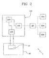
- Fig. 2 diagrammatically shows a combination of components through which the contents of memory 10 of the portable apparatus 80 can be set.
- this configuration system 1 comprises a main computer 100; the main computer 100 can consist of a conventional PC for instance, which is suitably configured for performing the functions hereinafter described.
- the main computer 100 is provided with a first communication module 110, for communicating with a reading device and receiving identification data ID of structures 30, 40, 50, from the respective identification devices 30a, 40a, 50a.
- the first communication module 110 may comprise a wireless module (a Bluetooth ® module, for example) or any other communication interface to enable the aforesaid data to be received from said reading device.
- a wireless module a Bluetooth ® module, for example
- any other communication interface to enable the aforesaid data to be received from said reading device.
- the reading device with which the first communication module 110 can communicate is said reading device 20 associated with the portable apparatus 80.
- identification codes are read in the identification devices 30a, 40a, 50a, which codes will be then associated with structures 30, 40, 50 for uniquely identifying the latter.
- the identification devices 30a, 40a, 50a preferably are not yet positioned at the respective structures, but they can be gathered in the vicinity of the main computer 100, so as to facilitate the starting operation concerning data input.
- the main computer 100 further comprises a main storage register 120 for storing the identification data ID received through the first communication module 110.
- the main computer 100 further comprises a second communication module 130 for communication with the first storage register 11 of memory 10 of the portable apparatus 80. Through the second communication module 130 at least part of the identification data ID stored in the main storage register 120 are transferred into memory 10 of the portable apparatus 80.
- the identification data ID transferred to memory 10 therefore constitute the above mentioned stored data SD, that will then be used for recognising the identification devices 30a, 40a, 50a and the structures 30, 40, 50 associated therewith.
- the main computer 100 can further comprise another communication module (not shown), for connection with a remote server, into which all data concerning planning and execution of control activities connected with safety are stored.
- another communication module (not shown), for connection with a remote server, into which all data concerning planning and execution of control activities connected with safety are stored.
- the main computer 100 is further provided with a planning module (not shown) enabling a user to schedule the different control and monitoring activities that are to be performed, through a suitable graphic interface for example.
- a planning module (not shown) enabling a user to schedule the different control and monitoring activities that are to be performed, through a suitable graphic interface for example.
- identification data ID contained in the main storage register 120 can be transferred to the first register 11 of memory 10 of the portable apparatus 80; in particular, it is advantageously possible to transfer the identification codes ID singling out only and all the structures that an operator has stated will the subject matter of the control activity.
- the decision on which structures are to be controlled can be taken with the backing of said planning module the function of which will be to supply the operator in charge with all information on scheduling of the inspections, the due dates, and the optimal or preferred path in the spaces in which the structures being the object of said inspection are located.
- the aforesaid setting step is directly performed by the portable apparatus 80, through the reading device 20, without the aid of the main computer 100; reading of the identification codes ID and the related storage in the first storage register 11 can exactly be performed directly by the portable apparatus 80, before the operator in charge starts the control and inspection procedures.
- the identification devices 30a, 40a, 50a can be already positioned with the respective structures 30, 40, 50 also before the initial system setting step is carried out.
- an initial setting step is performed in which, by means of the reading device 20, the contents of the identification devices 30a, 40a, 50 are read. These contents are identification data ID of structures 30, 40, 50 that are to be monitored.
- the identification data ID preferably by means of the main computer 100, are transferred to the first register 11 of memory 10 of the portable apparatus 80.
- each identification device 30a, 40a, 50a after reading, is positioned in the vicinity of the respective structure 30, 40, 50.
- the control activity can start being performed by the operator entrusted with this task; the operator is provided with the reading device 20 and the portable apparatus 80.
- the operator moves at the inside of the environment where structures 30, 40, 50 are, going close to each of them in succession. For instance, when he/she is close to structure 30 (an extinguisher, for example), he/she moves the reading device 20 close to the identification device 30a that is positioned in the vicinity of structure 30, so that the reading device 20 can supply the portable apparatus 80 with the detected datum DD read by said identification device 30a.
- the processing unit 60 compares the detected datum DD with the different stored data SD and, if everything has occurred in a correct manner, verifies whether the detected datum DD is the same as one of the stored data SD. Then the processing unit 60 generates the activation signal AS, so as to drive the user interface 80 to the second operating condition.
- the operator can therefore input the monitoring data MD, representative of said procedures and of the pertinent results.
- the portable apparatus 80 can be connected again to the main computer 100, so that the collected data can be downloaded into the main storage register 120 and possibly transmitted to the aforesaid remote server.
- the reading device 20 is suitably associated with a portable apparatus 80; preferably, the reading device 20 is integrated into this portable apparatus 80.
- the portable apparatus 80 enables the operator, through data input means 71, to input the monitoring data MD relating to structures 30, 40, 50, which structures are identified through reading of the respective identification devices 30a, 40a, 50a.
- This data input means 71 can even comprise only two buttons or equivalent means, for example; one button for inputting a datum of the type "in compliance” (i.e., following the control carried out, the operator has judged that the structure in question has no problems, i.e. is in compliance with the regulations in force), and one button for inputting a datum of the type "not in compliance” (i.e. following the control carried out, the operator has judged that the structure in question does not comply with one or more of the safety criteria).
- the monitoring data MD thus inputted can be stored in suitable storage means 10 integrated into the portable apparatus 80.
- apparatus 80 can be provided with a memory 10, in which the identification codes detected by the reading device 20 are stored, said codes being suitably combined with the respective monitoring data MD inputted by the operator.
- the portable apparatus 80 can be connected to a main computer 100, into which the data stored in the memory of apparatus 80 are downloaded.
- the data stored in the memory of apparatus 80 are transferred to memory 120 of the main computer 100 so that the latter can keep a trace of the origin or source of these data; for instance, the monitoring data MD and the respective identification codes of the structures can be associated with an identifier of the operator who has performed said inspections.
- the main computer 100 will be preferably able to carry out controls on the received data, checking, for instance, whether the examined structures actually pertained to that operator, whether the latter did not omit any of the structures that he/she should have taken into consideration, etc.
- the main computer 100 can be provided with one or more storage registers in which the identification codes of the structures that are to be the object of an inspection and/or control are listed, said codes being suitably divided (through association with identifiers representative of the different operators, for example), depending on the operator who is designed to be responsible for said structures.
- the portable apparatus 80 can comprise a wireless transmission module 81 enabling a transmission substantially in real time of the detected data by means of the reading device 20, and of an identifier representative of the operator.
- the main computer 100 will then be provided with a wireless reception module 101, operation of which will be exactly the same as described above; controls will be carried out on data received by means of this wireless reception module 101.
- Wireless transmission of the monitoring data MD and the identification codes of the respective structures can be provided in place of, or also in combination with storage of this information in the memory 10 of the portable apparatus 80.
- the main computer 100 will be also able to update its database concerning due dates and scheduling of inspections.
- the monitoring data MD inputted through the data input means 71, can be stored in memories 30b, 40b, 50b integrated into the identification devices 30a, 40a, 50a.
- the portable apparatus 80 can then be provided with a writing device 21, such as a device adapted to write data on the memory being part of a RFID tag, for example.
- a writing device 21 such as a device adapted to write data on the memory being part of a RFID tag, for example.
- the monitoring data MD in this case can comprise the inspection date and/or the result of said inspection, for example.
- the step of transferring the monitoring data MD to the main computer through wireless transmission or by storage into the memory of the portable apparatus 80 and subsequent download to the main computer) can also be avoided.
- the operator On occurrence of the subsequent control, through the reading device 20, the operator will be able to detect not only the identification codes associated with structures 30, 40, 50, but also the respective monitoring data inputted during the preceding control.
- the invention achieves important advantages.
- the system according to the invention enables more efficiency and reliability to be obtained in the safety controls carried out.
- system of the invention allows the inspection/verification operations of the structures present in a given environment to be simplified and automated.
Claims (14)
- Verfahren zur Überwachung von Strukturen (30, 40, 50), umfassend:- Bereitstellen einer Nahbereichslesevorrichtung (20), die dazu geeignet ist, Erfassungsdaten (DD), die mindestens eine der Strukturen (30, 40, 50) identifizieren, von Identifizierungsvorrichtungen (30a, 40a, 50a) zu lesen, die mit Strukturen (30, 40, 50) assoziiert sind;- Bereitstellen eines tragbaren Geräts (80), das dazu konfiguriert ist, mit der Lesevorrichtung (20) zusammenzuwirken, umfassend:• einen Speicher (10), der wiederum mindestens ein erstes Register (11) beinhaltet, das gespeicherte Daten (SD) enthält, die Strukturen (30, 40, 50) identifizieren;• eine Verarbeitungseinheit (60), die wirksam mit dem Speicher (10) und der Lesevorrichtung (20) assoziiert ist;• eine Benutzerschnittstelle (70), die Dateneingabemittel (71) bildet um das Eingeben von Überwachungsdaten (MD), die sich auf die Strukturen (30, 40, 50) beziehen, durch einen Bediener zu ermöglichen;- Bereitstellen eines Hauptcomputers (100), der zu Folgendem konfiguriert ist:• Kommunizieren, mittels eines ersten Kommunikationsmoduls (110), mit einer Lesevorrichtung und Empfangen von Identifizierungsdaten (ID) für die Strukturen (30, 40, 50) von den Identifizierungsvorrichtungen (30a, 40a, 50a);
wobei die Lesevorrichtung, mit der das erste Kommunikationsmodul (110) kommunizieren kann, die Lesevorrichtung (20) ist, die mit dem tragbaren Gerät (80) assoziiert ist;• Speichern der Identifizierungsdaten (ID) der Strukturen (30, 40, 50), die vom ersten Kommunikationsmodul (110) empfangen werden, in einem Hauptspeicherregister (120);• Kommunizieren, mittels eines zweiten Kommunikationsmoduls (130), mit dem ersten Register (11) des Speichers (10), um dort hinein eine Übertragung mindestens eines Teils der Identifizierungsdaten (ID), die im Hauptspeicherregister (120) gespeichert sind, durchzuführen,wobei das Verfahren die folgenden Schritte umfasst:
wobei die zum Speicher (10) übertragenen Identifizierungsdaten (ID) die gespeicherten Daten (SD) bilden, wobei die Daten dazu fähig sind, zum Erkennen der Identifizierungsvorrichtungen (30a, 40a, 50a) und der damit assoziierten Strukturen (30, 40, 50) verwendet zu werden;• Lernen und Einstellen, ferner umfassend die folgenden Schritte:o Sammeln von Identifizierungsvorrichtungen (30a, 40a, 50a) in der Nähe des Hauptcomputers (100), sodass der Startvorgang hinsichtlich der Dateneingabe vereinfacht wird;o Lesen von Identifizierungscodes in den Identifizierungsvorrichtungen (30a, 40a, 50a) mittels der Lesevorrichtung (20), wobei die Inhalte Identifizierungsdaten (ID) der zu überwachenden Strukturen (30, 40, 50) sind, wobei die Identifizierungsvorrichtungen (30a, 40a, 50a) noch nicht an den entsprechenden Strukturen (30, 40, 50) positioniert sind;o Übertragen der Identifizierungsdaten (ID) mittels eines Hauptcomputers (100), im Besonderen durch das zweite Kommunikationsmodul (130), an ein erstes Register (11) des Speichers (10) eines tragbaren Geräts (80); wobei das erste Register (11) gespeicherte Daten (SD) enthält, die Strukturen (30, 40, 50) identifizieren;o Positionieren einer jeden Identifizierungsvorrichtung (30a, 40a, 50a), nach dem Lesen, in der Nähe der entsprechenden Struktur (30, 40, 50);• Regeln der Aktivität, ferner umfassend die folgenden Schritte:o Bewegen der Nahbereichslesevorrichtung (20) nahe zur Identifizierungsvorrichtung (30a), die in der Nähe der Struktur (30) positioniert ist, sodass die Nahbereichslesevorrichtung (20) das tragbare Gerät (80) mit einem erfassten Datum (DD), das von der Identifizierungsvorrichtung (30a) gelesen wurde, versorgen kann;o Vergleichen, mittels der Verarbeitungseinheit (60), des erfassten Datums (DD) mit den gespeicherten Daten (SD) und Verifizieren, ob das erfasste Datum (DD) dasselbe wie eines der gespeicherten Daten (SD) ist;o Erzeugen, mittels der Verarbeitungseinheit (60), eines Aktivierungssignals (AS), sodass die Benutzerschnittstelle (70) von einem ersten Betriebszustand, in dem nur das Darstellen von Daten gestattet wird, in einen zweiten Betriebszustand, in dem das Eingeben der Überwachungsdaten (MD) durch den Bediener ermöglicht wird, gesteuert wird. - Verfahren zur Überwachung von Strukturen (30, 40, 50) nach Anspruch 1, ferner umfassend die folgenden Schritte:o Speichern, in einem Hauptspeicherregister (120), der Identifizierungsdaten (ID) der Strukturen (30, 40, 50), die vom ersten Kommunikationsmodul (110) empfangen werden;o Kommunizieren, mittels eines zweiten Kommunikationsmoduls (130), mit dem ersten Register (11) des Speichers (10), um dort hinein eine Übertragung mindestens eines Teils der Identifizierungsdaten (ID), die im Hauptspeicherregister (120) gespeichert sind, durchzuführen,wobei die Identifizierungsdaten (ID), die vom Hauptspeicherregister (120) zum ersten Register (11) des Speichers (10) übertragen werden, die gespeicherten Daten (SD) definieren, die im ersten Register (11) des Speichers (10) gespeichert sind.
- Verfahren zur Überwachung von Strukturen (30, 40, 50) nach Anspruch 2, ferner umfassend die folgenden Schritte:• Eingeben von Daten, ferner umfassend die folgenden Schritte:o Eingeben von Überwachungsdaten (MD), mittels Dateneingabemitteln (71), die sich auf die mindestens eine Struktur (30, 40, 50) beziehen;o Speichern der Überwachungsdaten (MD) in Speichermitteln (10; 30b, 40b, 50b), die wirksam mit den Dateneingabemitteln (71) assoziiert sind.
- System zur Überwachung von Strukturen zum Durchführen des Verfahrens nach den Ansprüchen 1 bis 3, umfassend:- eine Nahbereichslesevorrichtung (20), die dazu geeignet ist, Erfassungsdaten (DD), die mindestens eine der Strukturen (30, 40, 50) identifizieren, von Identifizierungsvorrichtungen (30a, 40a, 50a) zu lesen, die mit Strukturen (30, 40, 50) assoziiert sind;- Dateneingabemittel (71), um das Eingeben von Überwachungsdaten (MD), die sich auf die mindestens eine Struktur (30, 40, 50) beziehen, durch einen Bediener in das System zu ermöglichen;- Speichermittel (12; 30b, 40b, 50b, 120), die wirksam mit den Dateneingabemitteln (71) zum Speichern der Überwachungsdaten (MD) assoziiert sind;- ein tragbares Gerät (80), umfassend einen Speicher (10), der wiederum mindestens ein erstes Register (11) beinhaltet, das gespeicherte Daten (SD) enthält, die Strukturen (30, 40, 50) identifizieren;- einen Hauptcomputer (100), der mit Folgendem versehen ist:• einem ersten Kommunikationsmodul (110) zum Kommunizieren mit einer Lesevorrichtung und zum Empfangen von Identifizierungsdaten (ID) für die Strukturen (30, 40, 50) von den Identifizierungsvorrichtungen (30a, 40a, 50a);• einem Hauptspeicherregister (120), in dem die Identifizierungsdaten (ID) der Strukturen (30, 40, 50), die vom ersten Kommunikationsmodul (110) empfangen werden, gespeichert sind;• einem zweiten Kommunikationsmodul (130) zum Kommunizieren mit dem ersten Register (11) des Speichers (10), um dort hinein eine Übertragung mindestens eines Teils der Identifizierungsdaten (ID), die im Hauptspeicherregister (120) gespeichert sind, durchzuführen,wobei die Identifizierungsdaten (ID), die vom Hauptspeicherregister (120) zum ersten Register (11) des Speichers (10) übertragen werden, die gespeicherten Daten (SD) definieren, die im ersten Register (11) des Speichers (10) gespeichert sind;
wobei das tragbare Gerät (80) mit der Lesevorrichtung (20) assoziiert ist und mit Folgendem versehen ist:• einer Verarbeitungseinheit (60), die wirksam mit dem Speicher (10) und der Lesevorrichtung (20) assoziiert ist, um die gespeicherten Daten (SD) mit den Erfassungsdaten (DD) zu vergleichen;• einer Benutzerschnittstelle (70), die die Dateneingabemittel (71) definiert und wirksam mit der Verarbeitungseinheit (60) verriegelt ist, um im Falle einer Übereinstimmung zwischen den gespeicherten Daten (SD) und den Erfassungsdaten (DD) das Eingeben der Überwachungsdaten (MD), die sich auf die mindestens eine Struktur (30, 40, 50) beziehen, durch einen Bediener zu ermöglichen. - System nach Anspruch 4, wobei die Lesevorrichtung (20) ein RFID-Markierungsleser ist.
- System nach einem der Ansprüche 4 bis 5, wobei jede Identifizierungsvorrichtung (30a, 40a, 50a) eine RFID-Markierung umfasst, wobei jede davon mit einer entsprechenden Struktur (30, 40, 50) assoziiert ist.
- System nach einem der Ansprüche 4 bis 6, wobei die Überwachungsdaten (MD) für einen Überwachungs- oder Kontrollvorgang repräsentativ sind, der vom Bediener auf die mindestens eine Struktur (30, 40, 50) durchgeführt wird.
- System nach Anspruch 7, wobei die Benutzerschnittstelle (70) zwischen einem ersten Betriebszustand, in dem das Eingeben der Überwachungsdaten (MD) nicht gestattet wird, und einem zweiten Betriebszustand, in dem das Eingeben der Überwachungsdaten (MD) gestattet wird, gesteuert wird.
- System nach Anspruch 8, wobei die Verarbeitungseinheit (60) so konfiguriert ist, dass im Falle einer Übereinstimmung zwischen den gespeicherten Daten (SD) und den Erfassungsdaten (DD) ein Aktivierungssignal (AS) erzeugt wird, um die Benutzerschnittstelle (70) zum zweiten Betriebszustand zu steuern.
- System nach Anspruch 4, wobei die Speichermittel ein zweites Register (12), das ein Teil des Speichers (10) ist, zum Speichern der Überwachungsdaten (MD) der mindestens einen Struktur (30, 40, 50) umfassen, wobei die Daten mit den gespeicherten Daten (SD) assoziiert sind, die die mindestens eine Struktur (30, 40, 50) identifizieren.
- System nach Anspruch 4, wobei die Speichermittel Speicher umfassen, die in die Identifizierungsvorrichtungen (30a, 40a, 50a) integriert sind.
- System nach Anspruch 4, wobei die Speichermittel mindestens einen Speicher umfassen, der in ein tragbares Gerät (80) integriert ist, das wirksam mit der Lesevorrichtung (20) assoziiert ist.
- System nach Anspruch 4 oder 14, ferner umfassend ein tragbares Gerät (80), das mindestens mit einem Übertragungsmodul (81) versehen ist, um die Überwachungsdaten (MD) an einen Hauptcomputer (100) zu senden.
- System nach Anspruch 13, wobei das Übertragungsmodul (81) zum Senden der Überwachungsdaten (MD) und der Erfassungsdaten (DD), welche die Struktur/en, auf die sich die Überwachungsdaten (MD) beziehen, identifizieren, zum Hauptcomputer (100) konfiguriert ist.
Priority Applications (1)
| Application Number | Priority Date | Filing Date | Title |
|---|---|---|---|
| EP09425154.3A EP2244231B1 (de) | 2009-04-23 | 2009-04-23 | Vorrichtung zur Überwachung von Strukturen |
Applications Claiming Priority (1)
| Application Number | Priority Date | Filing Date | Title |
|---|---|---|---|
| EP09425154.3A EP2244231B1 (de) | 2009-04-23 | 2009-04-23 | Vorrichtung zur Überwachung von Strukturen |
Publications (2)
| Publication Number | Publication Date |
|---|---|
| EP2244231A1 EP2244231A1 (de) | 2010-10-27 |
| EP2244231B1 true EP2244231B1 (de) | 2014-06-11 |
Family
ID=41016852
Family Applications (1)
| Application Number | Title | Priority Date | Filing Date |
|---|---|---|---|
| EP09425154.3A Not-in-force EP2244231B1 (de) | 2009-04-23 | 2009-04-23 | Vorrichtung zur Überwachung von Strukturen |
Country Status (1)
| Country | Link |
|---|---|
| EP (1) | EP2244231B1 (de) |
Families Citing this family (2)
| Publication number | Priority date | Publication date | Assignee | Title |
|---|---|---|---|---|
| CN103699914A (zh) * | 2013-12-16 | 2014-04-02 | 上海市政工程设计研究总院(集团)有限公司 | 工程结构的病害检查电子化系统 |
| CN103699913A (zh) * | 2013-12-16 | 2014-04-02 | 上海市政工程设计研究总院(集团)有限公司 | 工程结构养护检查电子读写装置 |
Citations (2)
| Publication number | Priority date | Publication date | Assignee | Title |
|---|---|---|---|---|
| WO2004013785A2 (en) * | 2002-07-31 | 2004-02-12 | Sap Aktiengesellschaft | Tagging with maintenance related information |
| EP1647917A2 (de) * | 2004-09-24 | 2006-04-19 | Assa Abloy Identification Technology Group AB | RFID System mit herprogrammierbaren RFID-Leser |
Family Cites Families (3)
| Publication number | Priority date | Publication date | Assignee | Title |
|---|---|---|---|---|
| US6671646B2 (en) * | 2001-09-11 | 2003-12-30 | Zonar Compliance Systems, Llc | System and process to ensure performance of mandated safety and maintenance inspections |
| US8292172B2 (en) * | 2003-07-29 | 2012-10-23 | General Electric Company | Enhanced recordation device for rail car inspections |
| WO2005013172A2 (en) * | 2003-07-29 | 2005-02-10 | General Electric Company | Inspection data recording apparatus and method |
-
2009
- 2009-04-23 EP EP09425154.3A patent/EP2244231B1/de not_active Not-in-force
Patent Citations (2)
| Publication number | Priority date | Publication date | Assignee | Title |
|---|---|---|---|---|
| WO2004013785A2 (en) * | 2002-07-31 | 2004-02-12 | Sap Aktiengesellschaft | Tagging with maintenance related information |
| EP1647917A2 (de) * | 2004-09-24 | 2006-04-19 | Assa Abloy Identification Technology Group AB | RFID System mit herprogrammierbaren RFID-Leser |
Also Published As
| Publication number | Publication date |
|---|---|
| EP2244231A1 (de) | 2010-10-27 |
Similar Documents
| Publication | Publication Date | Title |
|---|---|---|
| CN101339671B (zh) | 用于在加工或其他环境中的资产检查期间捕获信息的设备和方法 | |
| JP6583384B2 (ja) | プラント設備の管理システム及び管理方法 | |
| CN101160610B (zh) | 集合设备 | |
| JP4378772B2 (ja) | データ端末装置及び設備管理システム | |
| KR102374570B1 (ko) | 설비 관리 시스템 | |
| US20080021717A1 (en) | Method of Facilitating Controlled Flow of Information for Safety Equipment Items and Database Related Thereto | |
| CN105378810A (zh) | 测量数据的远程共享 | |
| CN102096398A (zh) | 用于管理过程控制状态汇总的方法和装置 | |
| WO2007146735A2 (en) | Centralized databse of information related to inspection of safety equipment items inspection and method | |
| KR101965321B1 (ko) | 센서융합 디바이스 및 이를 이용한 실험실 통합관리 시스템 | |
| US11232703B1 (en) | Verification of visual inspection of a fire control system having self-testing components | |
| CN100451533C (zh) | 一种矿山智能爆破管理系统 | |
| WO2018076992A1 (zh) | 生产线监控系统和方法 | |
| US20080021905A1 (en) | Direct Data Input for Database for Safety Equipment Items and Method | |
| JP2008052480A (ja) | 保守点検支援システム、およびこれに利用する保守点検支援装置、保守点検支援プログラム | |
| KR20190128128A (ko) | 소화기 정보 관리시스템 | |
| EP2546815B1 (de) | System und Verfahren zur Alarminstallation und -konfiguration | |
| EP2244231B1 (de) | Vorrichtung zur Überwachung von Strukturen | |
| CN109308746A (zh) | 一种基于物联网的石化企业智能巡检系统及方法 | |
| JPH0635923A (ja) | 作業管理システム | |
| KR101721839B1 (ko) | Nfc 기반 원자력 발전소의 인적오류 예방 방법 | |
| JP2008276297A (ja) | 機器情報管理システム | |
| CN113219913A (zh) | 厂房管理系统 | |
| CN109684409B (zh) | 盾构施工监管方法 | |
| CN113219911A (zh) | 厂房管理系统 |
Legal Events
| Date | Code | Title | Description |
|---|---|---|---|
| PUAI | Public reference made under article 153(3) epc to a published international application that has entered the european phase |
Free format text: ORIGINAL CODE: 0009012 |
|
| AK | Designated contracting states |
Kind code of ref document: A1 Designated state(s): AT BE BG CH CY CZ DE DK EE ES FI FR GB GR HR HU IE IS IT LI LT LU LV MC MK MT NL NO PL PT RO SE SI SK TR |
|
| AX | Request for extension of the european patent |
Extension state: AL BA RS |
|
| 17P | Request for examination filed |
Effective date: 20110408 |
|
| 17Q | First examination report despatched |
Effective date: 20110506 |
|
| GRAP | Despatch of communication of intention to grant a patent |
Free format text: ORIGINAL CODE: EPIDOSNIGR1 |
|
| INTG | Intention to grant announced |
Effective date: 20131126 |
|
| GRAP | Despatch of communication of intention to grant a patent |
Free format text: ORIGINAL CODE: EPIDOSNIGR1 |
|
| INTG | Intention to grant announced |
Effective date: 20140304 |
|
| GRAS | Grant fee paid |
Free format text: ORIGINAL CODE: EPIDOSNIGR3 |
|
| GRAA | (expected) grant |
Free format text: ORIGINAL CODE: 0009210 |
|
| AK | Designated contracting states |
Kind code of ref document: B1 Designated state(s): AT BE BG CH CY CZ DE DK EE ES FI FR GB GR HR HU IE IS IT LI LT LU LV MC MK MT NL NO PL PT RO SE SI SK TR |
|
| REG | Reference to a national code |
Ref country code: GB Ref legal event code: FG4D |
|
| REG | Reference to a national code |
Ref country code: CH Ref legal event code: EP |
|
| REG | Reference to a national code |
Ref country code: IE Ref legal event code: FG4D |
|
| REG | Reference to a national code |
Ref country code: AT Ref legal event code: REF Ref document number: 672563 Country of ref document: AT Kind code of ref document: T Effective date: 20140715 |
|
| REG | Reference to a national code |
Ref country code: DE Ref legal event code: R096 Ref document number: 602009024578 Country of ref document: DE Effective date: 20140724 |
|
| REG | Reference to a national code |
Ref country code: CH Ref legal event code: NV Representative=s name: BUGNION S.A., CH |
|
| PG25 | Lapsed in a contracting state [announced via postgrant information from national office to epo] |
Ref country code: LT Free format text: LAPSE BECAUSE OF FAILURE TO SUBMIT A TRANSLATION OF THE DESCRIPTION OR TO PAY THE FEE WITHIN THE PRESCRIBED TIME-LIMIT Effective date: 20140611 Ref country code: GR Free format text: LAPSE BECAUSE OF FAILURE TO SUBMIT A TRANSLATION OF THE DESCRIPTION OR TO PAY THE FEE WITHIN THE PRESCRIBED TIME-LIMIT Effective date: 20140912 Ref country code: FI Free format text: LAPSE BECAUSE OF FAILURE TO SUBMIT A TRANSLATION OF THE DESCRIPTION OR TO PAY THE FEE WITHIN THE PRESCRIBED TIME-LIMIT Effective date: 20140611 Ref country code: NO Free format text: LAPSE BECAUSE OF FAILURE TO SUBMIT A TRANSLATION OF THE DESCRIPTION OR TO PAY THE FEE WITHIN THE PRESCRIBED TIME-LIMIT Effective date: 20140911 |
|
| REG | Reference to a national code |
Ref country code: NL Ref legal event code: VDEP Effective date: 20140611 |
|
| REG | Reference to a national code |
Ref country code: AT Ref legal event code: MK05 Ref document number: 672563 Country of ref document: AT Kind code of ref document: T Effective date: 20140611 |
|
| REG | Reference to a national code |
Ref country code: LT Ref legal event code: MG4D |
|
| PG25 | Lapsed in a contracting state [announced via postgrant information from national office to epo] |
Ref country code: LV Free format text: LAPSE BECAUSE OF FAILURE TO SUBMIT A TRANSLATION OF THE DESCRIPTION OR TO PAY THE FEE WITHIN THE PRESCRIBED TIME-LIMIT Effective date: 20140611 Ref country code: HR Free format text: LAPSE BECAUSE OF FAILURE TO SUBMIT A TRANSLATION OF THE DESCRIPTION OR TO PAY THE FEE WITHIN THE PRESCRIBED TIME-LIMIT Effective date: 20140611 Ref country code: SE Free format text: LAPSE BECAUSE OF FAILURE TO SUBMIT A TRANSLATION OF THE DESCRIPTION OR TO PAY THE FEE WITHIN THE PRESCRIBED TIME-LIMIT Effective date: 20140611 |
|
| PG25 | Lapsed in a contracting state [announced via postgrant information from national office to epo] |
Ref country code: RO Free format text: LAPSE BECAUSE OF FAILURE TO SUBMIT A TRANSLATION OF THE DESCRIPTION OR TO PAY THE FEE WITHIN THE PRESCRIBED TIME-LIMIT Effective date: 20140611 Ref country code: EE Free format text: LAPSE BECAUSE OF FAILURE TO SUBMIT A TRANSLATION OF THE DESCRIPTION OR TO PAY THE FEE WITHIN THE PRESCRIBED TIME-LIMIT Effective date: 20140611 Ref country code: PT Free format text: LAPSE BECAUSE OF FAILURE TO SUBMIT A TRANSLATION OF THE DESCRIPTION OR TO PAY THE FEE WITHIN THE PRESCRIBED TIME-LIMIT Effective date: 20141013 Ref country code: SK Free format text: LAPSE BECAUSE OF FAILURE TO SUBMIT A TRANSLATION OF THE DESCRIPTION OR TO PAY THE FEE WITHIN THE PRESCRIBED TIME-LIMIT Effective date: 20140611 Ref country code: ES Free format text: LAPSE BECAUSE OF FAILURE TO SUBMIT A TRANSLATION OF THE DESCRIPTION OR TO PAY THE FEE WITHIN THE PRESCRIBED TIME-LIMIT Effective date: 20140611 Ref country code: CZ Free format text: LAPSE BECAUSE OF FAILURE TO SUBMIT A TRANSLATION OF THE DESCRIPTION OR TO PAY THE FEE WITHIN THE PRESCRIBED TIME-LIMIT Effective date: 20140611 |
|
| PG25 | Lapsed in a contracting state [announced via postgrant information from national office to epo] |
Ref country code: NL Free format text: LAPSE BECAUSE OF FAILURE TO SUBMIT A TRANSLATION OF THE DESCRIPTION OR TO PAY THE FEE WITHIN THE PRESCRIBED TIME-LIMIT Effective date: 20140611 Ref country code: AT Free format text: LAPSE BECAUSE OF FAILURE TO SUBMIT A TRANSLATION OF THE DESCRIPTION OR TO PAY THE FEE WITHIN THE PRESCRIBED TIME-LIMIT Effective date: 20140611 Ref country code: IS Free format text: LAPSE BECAUSE OF FAILURE TO SUBMIT A TRANSLATION OF THE DESCRIPTION OR TO PAY THE FEE WITHIN THE PRESCRIBED TIME-LIMIT Effective date: 20141011 Ref country code: PL Free format text: LAPSE BECAUSE OF FAILURE TO SUBMIT A TRANSLATION OF THE DESCRIPTION OR TO PAY THE FEE WITHIN THE PRESCRIBED TIME-LIMIT Effective date: 20140611 |
|
| REG | Reference to a national code |
Ref country code: DE Ref legal event code: R097 Ref document number: 602009024578 Country of ref document: DE |
|
| PLBE | No opposition filed within time limit |
Free format text: ORIGINAL CODE: 0009261 |
|
| STAA | Information on the status of an ep patent application or granted ep patent |
Free format text: STATUS: NO OPPOSITION FILED WITHIN TIME LIMIT |
|
| PG25 | Lapsed in a contracting state [announced via postgrant information from national office to epo] |
Ref country code: DK Free format text: LAPSE BECAUSE OF FAILURE TO SUBMIT A TRANSLATION OF THE DESCRIPTION OR TO PAY THE FEE WITHIN THE PRESCRIBED TIME-LIMIT Effective date: 20140611 |
|
| 26N | No opposition filed |
Effective date: 20150312 |
|
| REG | Reference to a national code |
Ref country code: DE Ref legal event code: R097 Ref document number: 602009024578 Country of ref document: DE Effective date: 20150312 |
|
| PG25 | Lapsed in a contracting state [announced via postgrant information from national office to epo] |
Ref country code: BE Free format text: LAPSE BECAUSE OF FAILURE TO SUBMIT A TRANSLATION OF THE DESCRIPTION OR TO PAY THE FEE WITHIN THE PRESCRIBED TIME-LIMIT Effective date: 20140611 |
|
| PG25 | Lapsed in a contracting state [announced via postgrant information from national office to epo] |
Ref country code: SI Free format text: LAPSE BECAUSE OF FAILURE TO SUBMIT A TRANSLATION OF THE DESCRIPTION OR TO PAY THE FEE WITHIN THE PRESCRIBED TIME-LIMIT Effective date: 20140611 |
|
| PG25 | Lapsed in a contracting state [announced via postgrant information from national office to epo] |
Ref country code: MC Free format text: LAPSE BECAUSE OF FAILURE TO SUBMIT A TRANSLATION OF THE DESCRIPTION OR TO PAY THE FEE WITHIN THE PRESCRIBED TIME-LIMIT Effective date: 20140611 Ref country code: LU Free format text: LAPSE BECAUSE OF FAILURE TO SUBMIT A TRANSLATION OF THE DESCRIPTION OR TO PAY THE FEE WITHIN THE PRESCRIBED TIME-LIMIT Effective date: 20150423 |
|
| REG | Reference to a national code |
Ref country code: IE Ref legal event code: MM4A |
|
| REG | Reference to a national code |
Ref country code: FR Ref legal event code: PLFP Year of fee payment: 8 |
|
| PG25 | Lapsed in a contracting state [announced via postgrant information from national office to epo] |
Ref country code: IE Free format text: LAPSE BECAUSE OF NON-PAYMENT OF DUE FEES Effective date: 20150423 |
|
| PG25 | Lapsed in a contracting state [announced via postgrant information from national office to epo] |
Ref country code: MT Free format text: LAPSE BECAUSE OF FAILURE TO SUBMIT A TRANSLATION OF THE DESCRIPTION OR TO PAY THE FEE WITHIN THE PRESCRIBED TIME-LIMIT Effective date: 20140611 |
|
| REG | Reference to a national code |
Ref country code: FR Ref legal event code: PLFP Year of fee payment: 9 |
|
| PG25 | Lapsed in a contracting state [announced via postgrant information from national office to epo] |
Ref country code: BG Free format text: LAPSE BECAUSE OF FAILURE TO SUBMIT A TRANSLATION OF THE DESCRIPTION OR TO PAY THE FEE WITHIN THE PRESCRIBED TIME-LIMIT Effective date: 20140611 Ref country code: HU Free format text: LAPSE BECAUSE OF FAILURE TO SUBMIT A TRANSLATION OF THE DESCRIPTION OR TO PAY THE FEE WITHIN THE PRESCRIBED TIME-LIMIT; INVALID AB INITIO Effective date: 20090423 |
|
| PG25 | Lapsed in a contracting state [announced via postgrant information from national office to epo] |
Ref country code: CY Free format text: LAPSE BECAUSE OF FAILURE TO SUBMIT A TRANSLATION OF THE DESCRIPTION OR TO PAY THE FEE WITHIN THE PRESCRIBED TIME-LIMIT Effective date: 20140611 |
|
| PG25 | Lapsed in a contracting state [announced via postgrant information from national office to epo] |
Ref country code: TR Free format text: LAPSE BECAUSE OF FAILURE TO SUBMIT A TRANSLATION OF THE DESCRIPTION OR TO PAY THE FEE WITHIN THE PRESCRIBED TIME-LIMIT Effective date: 20140611 |
|
| REG | Reference to a national code |
Ref country code: FR Ref legal event code: PLFP Year of fee payment: 10 |
|
| PG25 | Lapsed in a contracting state [announced via postgrant information from national office to epo] |
Ref country code: MK Free format text: LAPSE BECAUSE OF FAILURE TO SUBMIT A TRANSLATION OF THE DESCRIPTION OR TO PAY THE FEE WITHIN THE PRESCRIBED TIME-LIMIT Effective date: 20140611 |
|
| PGFP | Annual fee paid to national office [announced via postgrant information from national office to epo] |
Ref country code: IT Payment date: 20190419 Year of fee payment: 11 Ref country code: DE Payment date: 20190621 Year of fee payment: 11 |
|
| PGFP | Annual fee paid to national office [announced via postgrant information from national office to epo] |
Ref country code: FR Payment date: 20190424 Year of fee payment: 11 |
|
| PGFP | Annual fee paid to national office [announced via postgrant information from national office to epo] |
Ref country code: CH Payment date: 20190426 Year of fee payment: 11 |
|
| PGFP | Annual fee paid to national office [announced via postgrant information from national office to epo] |
Ref country code: GB Payment date: 20190429 Year of fee payment: 11 |
|
| REG | Reference to a national code |
Ref country code: DE Ref legal event code: R119 Ref document number: 602009024578 Country of ref document: DE |
|
| REG | Reference to a national code |
Ref country code: CH Ref legal event code: PL |
|
| PG25 | Lapsed in a contracting state [announced via postgrant information from national office to epo] |
Ref country code: DE Free format text: LAPSE BECAUSE OF NON-PAYMENT OF DUE FEES Effective date: 20201103 Ref country code: FR Free format text: LAPSE BECAUSE OF NON-PAYMENT OF DUE FEES Effective date: 20200430 Ref country code: LI Free format text: LAPSE BECAUSE OF NON-PAYMENT OF DUE FEES Effective date: 20200430 Ref country code: CH Free format text: LAPSE BECAUSE OF NON-PAYMENT OF DUE FEES Effective date: 20200430 |
|
| GBPC | Gb: european patent ceased through non-payment of renewal fee |
Effective date: 20200423 |
|
| PG25 | Lapsed in a contracting state [announced via postgrant information from national office to epo] |
Ref country code: GB Free format text: LAPSE BECAUSE OF NON-PAYMENT OF DUE FEES Effective date: 20200423 |
|
| PG25 | Lapsed in a contracting state [announced via postgrant information from national office to epo] |
Ref country code: IT Free format text: LAPSE BECAUSE OF NON-PAYMENT OF DUE FEES Effective date: 20200423 |