EP2244045A2 - Plate heat exchanger with profiles - Google Patents
Plate heat exchanger with profiles Download PDFInfo
- Publication number
- EP2244045A2 EP2244045A2 EP10003998A EP10003998A EP2244045A2 EP 2244045 A2 EP2244045 A2 EP 2244045A2 EP 10003998 A EP10003998 A EP 10003998A EP 10003998 A EP10003998 A EP 10003998A EP 2244045 A2 EP2244045 A2 EP 2244045A2
- Authority
- EP
- European Patent Office
- Prior art keywords
- profiles
- heat exchanger
- plate heat
- passages
- plate
- Prior art date
- Legal status (The legal status is an assumption and is not a legal conclusion. Google has not performed a legal analysis and makes no representation as to the accuracy of the status listed.)
- Withdrawn
Links
Images
Classifications
-
- F—MECHANICAL ENGINEERING; LIGHTING; HEATING; WEAPONS; BLASTING
- F28—HEAT EXCHANGE IN GENERAL
- F28D—HEAT-EXCHANGE APPARATUS, NOT PROVIDED FOR IN ANOTHER SUBCLASS, IN WHICH THE HEAT-EXCHANGE MEDIA DO NOT COME INTO DIRECT CONTACT
- F28D9/00—Heat-exchange apparatus having stationary plate-like or laminated conduit assemblies for both heat-exchange media, the media being in contact with different sides of a conduit wall
- F28D9/0062—Heat-exchange apparatus having stationary plate-like or laminated conduit assemblies for both heat-exchange media, the media being in contact with different sides of a conduit wall the conduits for one heat-exchange medium being formed by spaced plates with inserted elements
-
- F—MECHANICAL ENGINEERING; LIGHTING; HEATING; WEAPONS; BLASTING
- F28—HEAT EXCHANGE IN GENERAL
- F28F—DETAILS OF HEAT-EXCHANGE AND HEAT-TRANSFER APPARATUS, OF GENERAL APPLICATION
- F28F1/00—Tubular elements; Assemblies of tubular elements
- F28F1/02—Tubular elements of cross-section which is non-circular
- F28F1/04—Tubular elements of cross-section which is non-circular polygonal, e.g. rectangular
- F28F1/045—Tubular elements of cross-section which is non-circular polygonal, e.g. rectangular with assemblies of stacked elements
-
- F—MECHANICAL ENGINEERING; LIGHTING; HEATING; WEAPONS; BLASTING
- F28—HEAT EXCHANGE IN GENERAL
- F28F—DETAILS OF HEAT-EXCHANGE AND HEAT-TRANSFER APPARATUS, OF GENERAL APPLICATION
- F28F3/00—Plate-like or laminated elements; Assemblies of plate-like or laminated elements
- F28F3/02—Elements or assemblies thereof with means for increasing heat-transfer area, e.g. with fins, with recesses, with corrugations
-
- F—MECHANICAL ENGINEERING; LIGHTING; HEATING; WEAPONS; BLASTING
- F28—HEAT EXCHANGE IN GENERAL
- F28F—DETAILS OF HEAT-EXCHANGE AND HEAT-TRANSFER APPARATUS, OF GENERAL APPLICATION
- F28F2225/00—Reinforcing means
- F28F2225/04—Reinforcing means for conduits
-
- F—MECHANICAL ENGINEERING; LIGHTING; HEATING; WEAPONS; BLASTING
- F28—HEAT EXCHANGE IN GENERAL
- F28F—DETAILS OF HEAT-EXCHANGE AND HEAT-TRANSFER APPARATUS, OF GENERAL APPLICATION
- F28F2275/00—Fastening; Joining
- F28F2275/04—Fastening; Joining by brazing
-
- Y—GENERAL TAGGING OF NEW TECHNOLOGICAL DEVELOPMENTS; GENERAL TAGGING OF CROSS-SECTIONAL TECHNOLOGIES SPANNING OVER SEVERAL SECTIONS OF THE IPC; TECHNICAL SUBJECTS COVERED BY FORMER USPC CROSS-REFERENCE ART COLLECTIONS [XRACs] AND DIGESTS
- Y10—TECHNICAL SUBJECTS COVERED BY FORMER USPC
- Y10T—TECHNICAL SUBJECTS COVERED BY FORMER US CLASSIFICATION
- Y10T29/00—Metal working
- Y10T29/49—Method of mechanical manufacture
- Y10T29/4935—Heat exchanger or boiler making
- Y10T29/49366—Sheet joined to sheet
Definitions
- the invention relates to a plate heat exchanger for heat exchange between at least two media consisting of a plurality of stacked passages, which are separated by baffles, and wherein the passages are structured, and a method for producing a plate heat exchanger.
- the invention will be described with reference to a plate heat exchanger made of aluminum, but is in principle applicable to any heat exchanger having the features according to the preamble of claim 1.
- the present invention is suitable for use in plate heat exchangers made of stainless steel or high-temperature steel, which are based on the so-called rod-plate principle.
- plate heat exchangers made of aluminum for heat exchange between at least two media from a plurality of stack-shaped arranged passages, which are separated by separating plates.
- the individual passages are in principle similar and arranged in parallel.
- the heat exchange between the participating in the heat exchange media takes place between adjacent passages, the passages and thus the media or pressure chambers through plates, commonly referred to as dividers, are separated.
- the heat exchange takes place by means of heat transfer via the separating plates.
- a wavy structure which forms the channels for guiding the medium.
- the wave crests of the wave-shaped structure are connected to the respective adjacent separating plates.
- the participating in the heat exchange media are thus in direct thermal contact with the wave-shaped structures, so that the heat transfer is ensured by the thermal contact between the wave crests and dividing plates.
- the orientation of the undulating structure is chosen as a function of the application such that the dc, dross, counter or cross counterflow between adjacent passages is made possible. This state of the art is also in the DE 103 43 107 described.
- the undulating structures within the passages fulfill three tasks. On the one hand, thermal contact between the wave-shaped structure and the separating plate ensures heat exchange between two media in adjacent passages. On the other hand, the wave-shaped structures make the connection to the separating plate. Thirdly, the flanks of the wave-shaped structure serve to initiate the forces resulting from the internal pressure into the connection between wave peak, solder and separating plate. According to the prior art, the solder is applied on both sides of the dividing plates, applied to the wave crests or introduced before the soldering process between wave structure and separating plate, whereby the direct contact between the separating plate and wave crest is produced. The resulting stack of passages with wavy structures and dividing plates can then be introduced according to the prior art as a complete stack in a soldering oven for soldering the stack.
- the undulating structures are made of thin sheets which are folded into wavy structures by means of a press or other tools suitable for deformation. Due to the boundary conditions to be met in the forming process, such as radii at the transition between wave crest and flank, and the tolerances occurring during the forming process with respect to the ideal shape to be achieved, the mechanical strength of a heat exchanger is limited, which when used with media under high pressures, high temperatures or combination from both problems. In order to further improve the mechanical strength of such a plate heat exchanger, suggests DE 103 43 107 to manufacture the undulating structures from a thick plate, either extruded warm or made by machining. In this case, further parameters are proposed for the ratio between the thickness of the undulating structure itself and its division, ie wavelength and wave amplitude.
- the present invention is based on the object, a plate heat exchanger and a method for producing such a Plate heat exchanger to design such that the strength of the plate heat exchanger is increased under high pressure.
- the present object is achieved in that at least one passage consists of a plurality of profiles.
- top, bottom, or side refer to viewing the passage in the plane in which the heat exchange media flow.
- the undulating structures within the passages are not formed by deformed sheets but by profiles.
- it is attempted to produce a substantially wave-shaped structure which has right-angled flanks in order to produce a sufficiently large contact surface between the solder and the separating plate and to achieve as vertical a force application on the separating plate as possible.
- this is difficult to achieve in terms of manufacturing technology.
- wave structures made of bent sheets two edges are usually not perpendicular to each other, but have radii and sloping flanks in the connection. This can be done with the in DE 103 43 107 Avoid proposed cutting process, but here is the rectangular shape usually lost by the soldering process.
- the radii on the undulating structure form a fillet weld between wave crest of the undulating structure and the separating plate.
- the solder usually has a significantly inhomogeneous structure compared to the base material of the undulating structure and the separating plate. Accumulations of brittle structure in the grooves lead in operation of the plate heat exchanger under high mechanical stresses to damage the soldering by cracks in the fillet weld. As a result, both the base material of the wavy structure is weakened and further damaged the connection to the separating plate.
- the wave-shaped structure is replaced by individual profiles, which are arranged side by side.
- profiles according to the invention the contact area between separating plate and structure of the passage is significantly increased.
- profiles with very good angles and strengths are on the market, so that the contact surface after the soldering process has substantially the same shape as before the soldering.
- the formation of a fillet weld, which can easily rupture under high pressure loading, is minimized by the present invention.
- the introduction of force is cheaper because the webs are almost perpendicular to these profiles and thus make it difficult to peel off the two contact surfaces of each other.
- At least one, preferably all, passage (s) are formed by hollow profiles arranged side by side.
- the interconnected hollow profiles have a square or a rectangular cross-section.
- the use of hollow profiles with a square or rectangular cross section results in flat or flat surfaces, which are very well suited for wetting with solder and thereby for contacting the hollow profiles with the adjacent dividing plates.
- the hollow profiles used can be in one piece, i. consisting of one piece, or multiple pieces, i. be composed of welded together profile parts, his.
- the hollow profiles are arranged such that there is no gap between them, ie two adjacent hollow profiles abut each other at their side edges.
- the media involved in the heat exchange flow within the hollow sections.
- the pressure load is also absorbed substantially by the hollow profiles. That is, in this embodiment of the invention, the pressure does not act as in the prior art primarily on the connection between wavy structure and separating plate, but is distributed by the hollow sections themselves much more uniform and introduced into the structure.
- the connection between the hollow profile and separating plate is exposed to significantly lower stresses, whereby the risk of peeling off the connection between the hollow profile and separating plate is again significantly minimized.
- the mechanical strength of the plate heat exchanger according to this embodiment of the invention is significantly increased over the prior art. Furthermore, the risk of deterioration of the heat transfer is minimized by a deterioration of the connection between hollow sections and separating plate.
- At least one, preferably all, passage / s is formed by juxtaposed double T-profiles.
- the contact area between the profile of the passage and separating plate is significantly higher than in the prior art.
- the double-T profiles are arranged in such / in the passages that the two bars of the double-T hit the dividers and the web is perpendicular to the separating plate between the beams.
- the contact between partition and profile is made via the two beams of the double-T.
- the profiles are preferably arranged such that there is no gap between them, i. the two bars of the double-T abut the two bars of the adjacent double-T.
- the pressure is thus absorbed essentially by the profile itself and does not affect the connection between the profile and separating plate.
- both the hollow profiles and the double-T profiles can thus be arranged at impact or at a distance from one another.
- the profiles on not connected to the dividing plates on perforations are connected to the dividing plates on perforations.
- the lateral perforation i. Openings of the profiles in the plane of the passage in which the heat exchange media flow allow a cross-mixing of the medium flowing in the passage. This further improves the heat transfer.
- the hollow profiles of a passage are completely or partially closed laterally.
- the profiles and the separating plates made of aluminum, steel, stainless steel, high-temperature steel and / or a nickel-based alloy. It can The materials mentioned can also be combined, for example, the profiles made of steel and the dividing plates can also be made of high-temperature steel.
- the plate heat exchanger according to the invention is particularly advantageously a plate heat exchanger, as used in different process segments in air separation plants, petrochemical plants, hydrogen plants or natural gas plants.
- natural gas plants for example, heat is withdrawn via the heat exchanger natural gas and the natural gas liquefied thereby and separated from the by-products.
- synthesis gas plants such a plate heat exchanger u.a. for the separation and further utilization of substances (H2, CO, CO2, CH4) or for preheating the starting materials.
- ethylene plants such heat exchangers are used for the separation of ethylene, in air separation plants find plate heat exchangers application in the condenser and evaporator.
- the desired material streams can be efficiently heated or cooled by means of the plate heat exchanger.
- the inventive method several profiles are arranged side by side, contacted with solder and placed on a separating plate.
- the next separating plate is placed under contact with solder on the juxtaposed profiles.
- the next layer of juxtaposed profiles can be applied under contact with a solder.
- a stack of several passages is created, which are separated by dividers are separated.
- the resulting passages are formed by a plurality of juxtaposed profiles.
- the entire stack can then be soldered together by introducing it into a soldering oven.
- the profiles can be arranged side by side on impact, ie without space between adjacent profiles, or with a gap. If the profiles are arranged side by side with clearance, their connection is made with each other via the common connection with the separating plate.
- the solder can be applied both to the profiles and to the separating plate.
- the solder is applied to the separating plate.
- a sidebar is understood to mean any profile of solid material which has the same height as the profiles which form the passage.
- the profiles are arranged side by side on impact.
- the hollow profiles are advantageously in the arrangement side by side with each other, preferably by means of welds, stitched.
- the stacking of the individual passages is simplified.
- the profiles do not necessarily have to be connected to one another, since they are also connected via the separating plate after the soldering of the stack.
- the present invention in particular, it is possible to provide a plate heat exchanger which is suitable for heat exchange between media under high mechanical stresses.
- the mechanical stability of the plate heat exchanger according to the invention is significantly improved over the prior art.
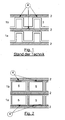
- FIG. 1 shows the passages 1a and 1b of a plate heat exchanger according to the prior art.
- a wave-shaped structure 3 which was made of a bent sheet metal.
- the adjacent passages 1 a and 1 b are separated by the separating plate 2 from each other.
- solder is applied. By soldering these solder joints, the entire heat exchanger is connected together. If two media for heat exchange under pressure are fed into the passages 1a and 1b, the entire passage 1a, 1b is under pressure. The pressure acts primarily on the connection points 4 between wave-shaped structure 3 and separating plate. 2
- FIG. 2 shows the passages 1 a and 1 b of an embodiment of the plate heat exchanger according to the invention.
- the passages 1a and 1b have a plurality of interconnected hollow profiles 5, which have a rectangular cross-section.
- the hollow profiles are connected in each case at the contact points 4 via solder with the separating plates 2.
- the contact surface and thus the connecting surface between the separating plate 2 and the structure of the passages 1a and 1b are significantly increased compared to the prior art.
- essentially only the hollow profiles 5 are under pressure. In a heat exchange between two media in the adjacent passages 1a and 1b, therefore, only the profiles 5 are under the high pressure of the media.
- the junction 4 between the hollow sections 5 and the separating plates 2 is not exposed to pressure.
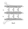
- FIG. 3 shows the passages 1a and 1b of a further embodiment of the plate heat exchanger according to the invention.
- the passages 1a and 1b have a
- the double-T profiles are connected at the contact points 4 via solder with the dividers 2.
- the contact surface and thus the connecting surface between separating plate 2 and the structure of the passages 1a and 1b are significantly increased compared to the prior art.
- essentially only the spaces between the double-T-profiles 6 are under pressure. In a heat exchange between two media in the adjacent passages 1a and 1b, therefore, only the double-T-profiles 6 are under the high pressure of the media.
- the connection point 4 between the double-T-profiles 6 and the separating plates 2 is not exposed to pressure.
Abstract
Description
Die Erfindung betrifft einen Plattenwärmeaustauscher zum Wärmeaustausch zwischen mindestens zwei Medien bestehend aus einer Vielzahl stapelförmig angeordneter Passagen, welche durch Trennbleche voneinander getrennt sind, und wobei die Passagen strukturiert sind, sowie ein Verfahren zur Herstellung eines Plattenwärmeaustauschers. Die Erfindung wird anhand eines Plattenwärmeaustauschers aus Aluminium beschrieben, ist aber prinzipiell für einen beliebigen Wärmetauscher anwendbar, der die Merkmale gemäß dem Oberbegriff des Anspruches 1 aufweist. Insbesondere ist die vorliegende Erfindung zur Anwendung bei Plattenwärmeaustauschern aus Edelstahl oder hochwarmfesten Stahl geeignet, welche auf dem sogenannten Stab-Platte-Prinzip beruhen.The invention relates to a plate heat exchanger for heat exchange between at least two media consisting of a plurality of stacked passages, which are separated by baffles, and wherein the passages are structured, and a method for producing a plate heat exchanger. The invention will be described with reference to a plate heat exchanger made of aluminum, but is in principle applicable to any heat exchanger having the features according to the preamble of claim 1. In particular, the present invention is suitable for use in plate heat exchangers made of stainless steel or high-temperature steel, which are based on the so-called rod-plate principle.
Üblicherweise bestehen Plattenwärmeaustauscher aus Aluminium zum Wärmeaustausch zwischen mindestens zwei Medien aus einer Vielzahl stapelförmig angeordneter Passagen, welche durch Trennbleche voneinander getrennt sind. Die einzelnen Passagen sind prinzipiell ähnlich und parallel angeordnet. Der Wärmeaustausch zwischen den am Wärmeaustausch teilnehmenden Medien findet dabei zwischen benachbarten Passagen statt, wobei die Passagen und somit die Medien bzw. Druckräume durch Bleche, üblicherweise als Trennbleche bezeichnet, voneinander getrennt sind. Der Wärmeaustausch erfolgt mittels Wärmeübertragung über die Trennbleche.Typically, plate heat exchangers made of aluminum for heat exchange between at least two media from a plurality of stack-shaped arranged passages, which are separated by separating plates. The individual passages are in principle similar and arranged in parallel. The heat exchange between the participating in the heat exchange media takes place between adjacent passages, the passages and thus the media or pressure chambers through plates, commonly referred to as dividers, are separated. The heat exchange takes place by means of heat transfer via the separating plates.
Nach dem Stand der Technik existiert innerhalb der einzelnen Passagen eine wellenförmige Struktur, die die Kanäle zur Führung des Mediums bildet. Die Wellenberge der wellenförmigen Struktur sind mit den jeweils benachbarten Trennblechen verbunden. Die am Wärmeaustausch teilnehmenden Medien sind somit im direkten Wärmekontakt mit den wellenförmigen Strukturen, so dass der Wärmeübergang durch den thermischen Kontakt zwischen den Wellenbergen und Trennblechen gewährleistet ist. Zur Optimierung der Wärmeübertragung wird die Ausrichtung der wellenförmigen Struktur in Abhängigkeit vom Anwendungsfall so gewählt, dass Gleich-, Kreuz-, Gegen- oder Kreuz-Gegenströmung zwischen benachbarten Passagen ermöglicht wird. Dieser Stand der Technik ist auch in der
Die wellenförmigen Strukturen innerhalb der Passagen erfüllen drei Aufgaben. Zum einen wird durch den thermischen Kontakt zwischen der wellenförmigen Struktur und dem Trennblech der Wärmeaustausch zwischen zwei Medien in benachbarten Passagen gewährleistet. Zum anderen stellen die wellenförmigen Strukturen die Verbindung zum Trennblech her. Zum dritten dienen die Flanken der wellenförmigen Struktur zur Einleitung der, durch den Innendruck entstehenden, Kräfte in die Verbindung zwischen Wellenberg, Lot und Trennblech. Nach dem Stand der Technik wird das Lot beidseitig auf die Trennbleche aufgetragen, auf die Wellenberge aufgetragen oder vor dem Lötvorgang zwischen Wellenstruktur und Trennblech eingebracht, wodurch der direkte Kontakt zwischen Trennblech und Wellenberg hergestellt wird. Der auf diese Art und Weise entstehende Stapel aus Passagen mit wellenförmigen Strukturen und Trennblechen kann anschließend nach dem Stand der Technik als gesamter Stapel in einem Lötofen zur Verlötung des Stapels eingebracht werden.The undulating structures within the passages fulfill three tasks. On the one hand, thermal contact between the wave-shaped structure and the separating plate ensures heat exchange between two media in adjacent passages. On the other hand, the wave-shaped structures make the connection to the separating plate. Thirdly, the flanks of the wave-shaped structure serve to initiate the forces resulting from the internal pressure into the connection between wave peak, solder and separating plate. According to the prior art, the solder is applied on both sides of the dividing plates, applied to the wave crests or introduced before the soldering process between wave structure and separating plate, whereby the direct contact between the separating plate and wave crest is produced. The resulting stack of passages with wavy structures and dividing plates can then be introduced according to the prior art as a complete stack in a soldering oven for soldering the stack.
Nach dem Stand der Technik werden die wellenförmigen Strukturen aus dünnen Blechen hergestellt, welche mit einer Presse oder anderen zur Verformung geeigneten Werkzeugen zu wellenförmigen Strukturen gefaltet werden. Durch die bei dem Umformprozess einzuhaltenden Randbedingungen, wie Radien am Übergang zwischen Wellenberg und Flanke, und die beim Umformprozess auftretenden Toleranzen hinsichtlich der zu erreichenden Idealform ist die mechanische Festigkeit eines Wärmetauschers begrenzt, was bei Anwendung mit Medien unter hohen Drücken, hohen Temperaturen oder der Kombination aus Beiden Probleme bereitet. Um die mechanische Festigkeit eines derartigen Plattenwärmeaustauschers weiter zu verbessern, schlägt die
Der vorliegenden Erfindung liegt die Aufgabe zugrunde, einen Plattenwärmeaustauscher sowie ein Verfahren zur Herstellung eines derartigen Plattenwärmeaustauschers derart auszugestalten, dass die Festigkeit des Plattenwärmeaustauschers unter hohem Druck erhöht wird.The present invention is based on the object, a plate heat exchanger and a method for producing such a Plate heat exchanger to design such that the strength of the plate heat exchanger is increased under high pressure.
Die vorliegende Aufgabe wird dadurch gelöst, dass mindestens eine Passage aus einer Vielzahl von Profilen besteht.The present object is achieved in that at least one passage consists of a plurality of profiles.
Im Rahmen dieser Anmeldung beziehen sich räumliche Begriffe wie oben, unten oder seitlich auf die Betrachtung der Passage in der Ebene, in der die am Wärmeaustausch beteiligten Medien strömen.For the purposes of this application, spatial terms such as top, bottom, or side refer to viewing the passage in the plane in which the heat exchange media flow.
Entgegen dem Stand der Technik werden die wellenförmigen Strukturen innerhalb der Passagen nicht durch umgeformte Bleche sondern durch Profile gebildet. Im Stand der Technik wird versucht eine im Wesentlichen wellenförmige Struktur herzustellen, die rechtwinklige Flanken aufweist, um eine hinreichend große Kontaktfläche zwischen Lot und Trennblech herzustellen und eine möglichst senkrechte Krafteinleitung am Trennblech zu erreichen. Dies ist jedoch fertigungstechnisch schwierig erreichbar. Bei Wellenstrukturen, die aus gebogenen Blechen hergestellt werden, stehen zwei Kanten in der Regel nicht senkrecht aufeinander, sondern weisen Radien und schräge Flanken in der Verbindung auf. Dies lässt sich zwar mit dem in
Bei dem erfindungsgemäßen Wärmetauscher wird dieser Nachteil vermieden. Gemäß der Erfindung wird die wellenförmige Struktur durch einzelne Profile ersetzt, welche nebeneinander angeordnet werden. Durch die erfindungsgemäße Verwendung von Profilen wird die Kontaktfläche zwischen Trennblech und Struktur der Passage deutlich vergrößert. Zusätzlich sind Profile mit sehr guten Winkligkeiten und Festigkeiten auf dem Markt vorhanden, so dass die Kontaktfläche auch nach dem Lötvorgang im Wesentlichen die gleiche Form wie vor dem Lötvorgang aufweist. Das Ausbilden einer Kehlnaht, welche bei Belastung unter hohem Druck leicht einreißen kann, wird durch die vorliegende Erfindung auf ein Minimum reduziert. Zudem ist die Krafteinleitung dadurch günstiger, da die Stege bei diesen Profilen nahezu senkrecht stehen und somit ein Abschälen der beiden Kontaktflächen voneinander erschweren.In the heat exchanger according to the invention, this disadvantage is avoided. According to the invention, the wave-shaped structure is replaced by individual profiles, which are arranged side by side. By the use of profiles according to the invention, the contact area between separating plate and structure of the passage is significantly increased. In addition, profiles with very good angles and strengths are on the market, so that the contact surface after the soldering process has substantially the same shape as before the soldering. The formation of a fillet weld, which can easily rupture under high pressure loading, is minimized by the present invention. In addition, the introduction of force is cheaper because the webs are almost perpendicular to these profiles and thus make it difficult to peel off the two contact surfaces of each other.
Gemäß einer bevorzugten Ausgestaltung der Erfindung wird/werden mindestens eine, bevorzugt alle, Passage/n durch nebeneinander angeordnete Hohlprofile gebildet. Bevorzugt weisen die miteinander verbundenen Hohlprofile einen quadratischen oder einen rechteckigen Querschnitt auf. Durch die Verwendung von Hohlprofilen mit quadratischem oder rechteckigem Querschnitt ergeben sich ebene bzw. plane Flächen, welche sehr gut zur Benetzung mit Lot und dadurch zur Kontaktierung der Hohlprofile mit den benachbarten Trennblechen geeignet sind. Die verwendeten Hohlprofile können dabei einteilig, d.h. aus einem Stück bestehend, oder mehrteilig, d.h. aus miteinander verschweißten Profilteilen zusammengesetzt, sein. Durch die Verwendung von quadratischen oder rechteckigen Hohlprofilen wird in dieser Ausgestaltung der Erfindung die Kontaktfläche zwischen Trennblechen und Profil der Passage bei ähnlicher Struktur im Vergleich zum Stand der Technik verdoppelt. Wo im Stand der Technik nur eine Kante Kontakt mit dem oberen oder unteren Trennblech hat, haben bei rechteckigen oder quadratischen Profilen in dieser Ausgestaltung der Erfindung jeweils die beiden gegenüberliegenden Seiten des Profils Kontakt mit dem Trennblech. Dadurch wird die Stabilität des Wärmetauschers wesentlich gesteigert.According to a preferred embodiment of the invention, at least one, preferably all, passage (s) are formed by hollow profiles arranged side by side. Preferably, the interconnected hollow profiles have a square or a rectangular cross-section. The use of hollow profiles with a square or rectangular cross section results in flat or flat surfaces, which are very well suited for wetting with solder and thereby for contacting the hollow profiles with the adjacent dividing plates. The hollow profiles used can be in one piece, i. consisting of one piece, or multiple pieces, i. be composed of welded together profile parts, his. By using square or rectangular hollow profiles, in this embodiment of the invention, the contact area between separating plates and profile of the passage with a similar structure is doubled in comparison to the prior art. Where only one edge in the prior art has contact with the upper or lower separating plate, in the case of rectangular or square profiles in this embodiment of the invention the two opposite sides of the profile in each case make contact with the separating plate. As a result, the stability of the heat exchanger is significantly increased.
Vorteilhafterweise sind die Hohlprofile derart angeordnet, dass sich zwischen ihnen kein Zwischenraum ergibt, d.h. zwei benachbarte Hohlprofile stoßen an ihren Seitenkanten aneinander. In dieser Ausgestaltung der Erfindung strömen die am Wärmeaustausch beteiligten Medien innerhalb der Hohlprofile. Somit wird die Druckbelastung auch im Wesentlichen von den Hohlprofilen aufgenommen. Das heißt in dieser Ausgestaltung der Erfindung wirkt der Druck nicht wie im Stand der Technik primär auf die Verbindung zwischen wellenförmiger Struktur und Trennblech, sondern wird durch die Hohlprofile selbst wesentlich gleichförmiger verteilt und in die Struktur eingeleitet. Somit wird die Verbindung zwischen Hohlprofil und Trennblech deutlich geringeren Beanspruchungen ausgesetzt, wodurch das Risiko des Abschälens der Verbindung zwischen Hohlprofil und Trennblech nochmals deutlich minimiert wird. Dadurch wird die mechanische Festigkeit des Plattenwärmeaustauschers gemäß dieser Ausgestaltung der Erfindung deutlich gegenüber dem Stand der Technik erhöht. Des Weiteren wird das Risiko der Verschlechterung des Wärmeübergangs durch eine Verschlechterung der Verbindung zwischen Hohlprofilen und Trennblech minimiert.Advantageously, the hollow profiles are arranged such that there is no gap between them, ie two adjacent hollow profiles abut each other at their side edges. In this embodiment of the invention, the media involved in the heat exchange flow within the hollow sections. Thus, the pressure load is also absorbed substantially by the hollow profiles. That is, in this embodiment of the invention, the pressure does not act as in the prior art primarily on the connection between wavy structure and separating plate, but is distributed by the hollow sections themselves much more uniform and introduced into the structure. Thus, the connection between the hollow profile and separating plate is exposed to significantly lower stresses, whereby the risk of peeling off the connection between the hollow profile and separating plate is again significantly minimized. Thereby, the mechanical strength of the plate heat exchanger according to this embodiment of the invention is significantly increased over the prior art. Furthermore, the risk of deterioration of the heat transfer is minimized by a deterioration of the connection between hollow sections and separating plate.
In einer anderen Ausgestaltung der Erfindung wird/werden mindestens eine, bevorzugt alle, Passage/n durch nebeneinander angeordnete Doppel-T-Profile gebildet. Auch in dieser Ausgestaltung der Erfindung ist die Kontaktfläche zwischen Profil der Passage und Trennblech deutlich höher als im Stand der Technik. Die Doppel-T-Profile sind dabei derart in der/den Passagen angeordnet, dass die beiden Balken des Doppel-T an die Trennbleche stoßen und der Steg zwischen den Balken senkrecht auf dem Trennblech steht. Die Kontaktierung zwischen Trennblech und Profil erfolgt über die beiden Balken des Doppel-T. Auch in dieser Ausgestaltung der Erfindung werden die Profile bevorzugt derart angeordnet, dass sich zwischen ihnen kein Zwischenraum ergibt, d.h. die beiden Balken des Doppel-T stoßen an die beiden Balken des benachbarten Doppel-T. Auch in dieser Ausgestaltung der Erfindung wird der Druck somit im Wesentlichen von dem Profil selbst aufgenommen und wirkt nicht auf die Verbindung zwischen Profil und Trennblech.In another embodiment of the invention, at least one, preferably all, passage / s is formed by juxtaposed double T-profiles. Also in this embodiment of the invention, the contact area between the profile of the passage and separating plate is significantly higher than in the prior art. The double-T profiles are arranged in such / in the passages that the two bars of the double-T hit the dividers and the web is perpendicular to the separating plate between the beams. The contact between partition and profile is made via the two beams of the double-T. Also in this embodiment of the invention, the profiles are preferably arranged such that there is no gap between them, i. the two bars of the double-T abut the two bars of the adjacent double-T. Also in this embodiment of the invention, the pressure is thus absorbed essentially by the profile itself and does not affect the connection between the profile and separating plate.
Je nach Höhe der mechanischen Beanspruchung des Plattenwärmeaustauschers können somit sowohl die Hohlprofile als auch die Doppel-T-Profile auf Stoß oder voneinander beabstandet angeordnet werden.Depending on the level of mechanical stress on the plate heat exchanger, both the hollow profiles and the double-T profiles can thus be arranged at impact or at a distance from one another.
Gemäß einer Ausgestaltung der Erfindung weisen die Profile an nicht mit den Trennblechen verbundenen Seiten Perforationen auf. Die seitlichen Perforation, d.h. Öffnungen der Profile in der Ebene der Passage, in der die am Wärmeaustausch beteiligten Medien strömen, erlauben eine Quervermischung, des in der Passage strömenden, Mediums. Dadurch wird der Wärmeübergang weiter verbessert.According to one embodiment of the invention, the profiles on not connected to the dividing plates on perforations. The lateral perforation, i. Openings of the profiles in the plane of the passage in which the heat exchange media flow allow a cross-mixing of the medium flowing in the passage. This further improves the heat transfer.
Gemäß einer anderen Ausgestaltung sind die Hohlprofile einer Passage seitlich ganz oder teilweise verschlossen.According to another embodiment, the hollow profiles of a passage are completely or partially closed laterally.
Vorteilhafterweise bestehen die Profile und die Trennbleche aus Aluminium, Stahl, Edelstahl, hochwarmfesten Stahl und/oder einer Nickelbasislegierung. Dabei können die genannten Materialien auch kombiniert werden, z.B. können die Profile aus Stahl und die Trennbleche auch hochwarmfesten Stahl ausgeführt werden.Advantageously, the profiles and the separating plates made of aluminum, steel, stainless steel, high-temperature steel and / or a nickel-based alloy. It can The materials mentioned can also be combined, for example, the profiles made of steel and the dividing plates can also be made of high-temperature steel.
Der erfindungsgemäße Plattenwärmeaustauscher ist besonders vorteilhaft ein Plattenwärmeaustauscher, wie er in unterschiedlichen Prozesssegmenten in Luftzerlegungsanlagen, petrochemischen Anlagen, Wasserstoffanlagen oder Erdgasanlagen eingesetzt wird. In Erdgasanlagen wird dabei beispielsweise über den Wärmeaustauscher Erdgas Wärme entzogen und das Erdgas dadurch verflüssigt und von den Nebenprodukten abgetrennt. Auch in Synthesegasanlagen kann ein solcher Plattenwärmeaustauscher u.a. zur Abtrennung und weiteren Verwertung von Stoffen (H2, CO, CO2, CH4) oder zur Vorwärmung der Einsatzstoffe eingesetzt werden. In Ethylenanlagen werden derartige Wärmeaustauscher zur Abtrennung von Ethylen eingesetzt, in Luftzerlegungsanlagen finden Plattenwärmeaustauscher Anwendung im Kondensator und Verdampfer. Allgemein können die gewünschten Stoffströme mit Hilfe des Plattenwärmeaustauschers effizient erwärmt oder abgekühlt werden.The plate heat exchanger according to the invention is particularly advantageously a plate heat exchanger, as used in different process segments in air separation plants, petrochemical plants, hydrogen plants or natural gas plants. In natural gas plants, for example, heat is withdrawn via the heat exchanger natural gas and the natural gas liquefied thereby and separated from the by-products. Even in synthesis gas plants, such a plate heat exchanger u.a. for the separation and further utilization of substances (H2, CO, CO2, CH4) or for preheating the starting materials. In ethylene plants such heat exchangers are used for the separation of ethylene, in air separation plants find plate heat exchangers application in the condenser and evaporator. In general, the desired material streams can be efficiently heated or cooled by means of the plate heat exchanger.
Verfahrensseitig wird die gestellte Aufgabe durch ein Verfahren zur Herstellung eines Plattenwärmeaustauschers mit folgenden Merkmalen gelöst:
- a) Anordnung einer Vielzahl von Profilen nebeneinander,
- b) Anordnung der Profile auf einem Trennblech unter Kontaktierung mit einem Lot,
- c) Anordnung eines Trennbleches auf der Vielzahl der Profile unter Kontaktierung mit einem Lot,
- d) Wiederholung der Schritte a) bis c) unter Entstehung eines Stapels aus nebeneinander angeordneten Profilen, wobei die einzelnen Lagen der nebeneinander angeordneten Profile durch Trennbleche getrennt sind und
- e) Löten des gesamten Stapels in einem Lötofen.
- a) arrangement of a plurality of profiles next to each other,
- b) arrangement of the profiles on a separating plate while contacting with a solder,
- c) arranging a separating plate on the multiplicity of profiles while contacting it with a solder,
- d) repetition of steps a) to c) to form a stack of juxtaposed profiles, wherein the individual layers of the juxtaposed profiles are separated by separating plates and
- e) Soldering the entire stack in a brazing furnace.
Nach dem erfindungsgemäßen Verfahren werden mehrere Profile nebeneinander angeordnet, mit Lot kontaktiert und auf ein Trennblech gebracht. Das nächstfolgende Trennblech wird unter Kontaktierung mit Lot auf die nebeneinander angeordneten Profile gelegt. Auf diesem Trennblech kann dann die nächste Lage nebeneinander angeordneter Profile unter Kontaktierung mit einem Lot aufgebracht werden. Derartig fortfahrend entsteht ein Stapel aus mehreren Passagen, welche durch Trennbleche getrennt sind. Die dabei entstehenden Passagen werden durch eine Vielzahl nebeneinander angeordneter Profile gebildet. Der gesamte Stapel kann dann durch ein Einbringen in einen Lötofen miteinander verlötet werden. Die Profile können dabei auf Stoß, d.h. ohne Zwischenraum zwischen benachbarten Profilen, oder mit einem Zwischenraum nebeneinander angeordnet werden. Werden die Profile mit Zwischenraum nebeneinander angeordnet, erfolgt ihre Verbindung miteinander über die gemeinsame Verbindung mit dem Trennblech. Das Lot kann sowohl auf die Profile als auch auf das Trennblech aufgebracht werden. Bevorzugt wird das Lot auf das Trennblech aufgebracht.According to the inventive method several profiles are arranged side by side, contacted with solder and placed on a separating plate. The next separating plate is placed under contact with solder on the juxtaposed profiles. On this baffle then the next layer of juxtaposed profiles can be applied under contact with a solder. Continuing like this, a stack of several passages is created, which are separated by dividers are separated. The resulting passages are formed by a plurality of juxtaposed profiles. The entire stack can then be soldered together by introducing it into a soldering oven. The profiles can be arranged side by side on impact, ie without space between adjacent profiles, or with a gap. If the profiles are arranged side by side with clearance, their connection is made with each other via the common connection with the separating plate. The solder can be applied both to the profiles and to the separating plate. Preferably, the solder is applied to the separating plate.
Die Passagen werden seitlich durch Randleisten, sogenannte Sidebars, begrenzt. Unter einer Randleiste wird im Rahmen dieser Erfindung ein beliebiges Profil aus Vollmaterial verstanden, welches die gleiche Höhe aufweist, wie die Profile, die die Passage bilden.The passages are bounded laterally by sidebars, so-called sidebars. In the context of this invention, a sidebar is understood to mean any profile of solid material which has the same height as the profiles which form the passage.
Vorteilhafterweise werden die Profile nebeneinander auf Stoß angeordnet. In dieser Ausgestaltung der Erfindung werden die Hohlprofile vorteilhafterweise bei der Anordnung nebeneinander miteinander, bevorzugt mittels Schweißpunkte, verheftet. Dadurch wird in dieser Ausgestaltung der Erfindung wird das Stapeln der einzelnen Passagen vereinfacht. Die Profile müssen jedoch nicht zwingend miteinander verbunden werden, da sie auch über das Trennblech nach dem Löten des Stapels verbunden sind.Advantageously, the profiles are arranged side by side on impact. In this embodiment of the invention, the hollow profiles are advantageously in the arrangement side by side with each other, preferably by means of welds, stitched. As a result, in this embodiment of the invention, the stacking of the individual passages is simplified. However, the profiles do not necessarily have to be connected to one another, since they are also connected via the separating plate after the soldering of the stack.
Mit der vorliegenden Erfindung gelingt es insbesondere einen Plattenwärmeaustauscher bereit zu stellen, welcher zum Wärmeaustausch zwischen Medien unter hohen mechanischen Beanspruchungen geeignet ist. Die mechanische Stabilität des erfindungsgemäßen Plattenwärmeaustauschers wird deutlich gegenüber dem Stand der Technik verbessert.With the present invention, in particular, it is possible to provide a plate heat exchanger which is suitable for heat exchange between media under high mechanical stresses. The mechanical stability of the plate heat exchanger according to the invention is significantly improved over the prior art.
Im Folgenden soll die Erfindung anhand eines Vergleiches eines Ausführungsbeispieles der Erfindung mit dem Stand der Technik näher erläutert werden.In the following, the invention will be explained in more detail with reference to a comparison of an embodiment of the invention with the prior art.
Es zeigen
- Figur 1
- eine Passage eines Plattenwärmeaustauschers nach dem Stand der Technik
Figur 2- eine Passage einer Ausgestaltung eines erfindungsgemäßen Plattenwärmeaustauschers mit einem Hohlprofil
Figur 3- eine Passage einer Ausgestaltung eines erfindungsgemäßen Plattenwärmeaustauschers mit einem Doppel-T-Profil
- FIG. 1
- a passage of a plate heat exchanger according to the prior art
- FIG. 2
- a passage of an embodiment of a plate heat exchanger according to the invention with a hollow profile
- FIG. 3
- a passage of an embodiment of a plate heat exchanger according to the invention with a double-T profile
Vielzahl miteinander verbundener Doppel-T-Profile 6 auf. Die Doppel-T-Profile sind dabei an den Kontaktstellen 4 über Lot mit den Trennblechen 2 verbunden. In dieser Ausgestaltung der Erfindung ist zum einen die Kontaktfläche und somit die Verbindungsfläche zwischen Trennblech 2 und Struktur der Passagen 1a und 1 b gegenüber dem Stand der Technik deutlich erhöht. Zum anderen stehen im Gegensatz zum Stand der Technik im Wesentlichen nur die Räume zwischen den Doppel-T-Profilen 6 unter Druck. Bei einem Wärmeaustausch zwischen zwei Medien in den benachbarten Passagen 1a und 1 b stehen daher auch nur die Doppel-T-Profile 6 unter dem hohen Druck der Medien. Die Verbindungsstelle 4 zwischen den Doppel-T-Profilen 6 und den Trennblechen 2 ist keinem Druck ausgesetzt.Variety of interconnected double T-
Claims (9)
Applications Claiming Priority (1)
| Application Number | Priority Date | Filing Date | Title |
|---|---|---|---|
| DE102009018247A DE102009018247A1 (en) | 2009-04-21 | 2009-04-21 | Plate heat exchanger with profiles |
Publications (2)
| Publication Number | Publication Date |
|---|---|
| EP2244045A2 true EP2244045A2 (en) | 2010-10-27 |
| EP2244045A3 EP2244045A3 (en) | 2013-03-27 |
Family
ID=42341411
Family Applications (1)
| Application Number | Title | Priority Date | Filing Date |
|---|---|---|---|
| EP10003998A Withdrawn EP2244045A3 (en) | 2009-04-21 | 2010-04-15 | Plate heat exchanger with profiles |
Country Status (5)
| Country | Link |
|---|---|
| US (1) | US20100263846A1 (en) |
| EP (1) | EP2244045A3 (en) |
| JP (1) | JP2010256006A (en) |
| CN (1) | CN101871739A (en) |
| DE (1) | DE102009018247A1 (en) |
Families Citing this family (9)
| Publication number | Priority date | Publication date | Assignee | Title |
|---|---|---|---|---|
| DE102009048103A1 (en) | 2009-10-02 | 2011-04-07 | Linde Aktiengesellschaft | Heat exchanger i.e. plate-type heat exchanger, for use in e.g. petrochemical plant, has sidebars soldered to block, and headers welded to intermediate piece, which is previously soldered to block |
| US9756764B2 (en) | 2011-08-29 | 2017-09-05 | Aerovironment, Inc. | Thermal management system for an aircraft avionics bay |
| US8995131B2 (en) * | 2011-08-29 | 2015-03-31 | Aerovironment, Inc. | Heat transfer system for aircraft structures |
| CN103453788A (en) * | 2013-08-30 | 2013-12-18 | 南京威安新材料科技有限公司 | Gas plate type heat exchanger |
| US20180045471A1 (en) * | 2015-03-05 | 2018-02-15 | Linde Aktiengesellschaft | 3d-printed heating surface element for a plate heat exchanger |
| LT3359902T (en) | 2015-10-08 | 2019-11-11 | Linde Ag | Method for manufacturing a lamella and a plate heat exchanger with a lamella manufactured by such a method |
| US20200166293A1 (en) * | 2018-11-27 | 2020-05-28 | Hamilton Sundstrand Corporation | Weaved cross-flow heat exchanger and method of forming a heat exchanger |
| JP2022522432A (en) * | 2019-02-25 | 2022-04-19 | レール・リキード-ソシエテ・アノニム・プール・レテュード・エ・レクスプロワタシオン・デ・プロセデ・ジョルジュ・クロード | Equipment for exchanging heat and substances |
| CN112524793B (en) * | 2019-09-17 | 2022-05-24 | 广东美的生活电器制造有限公司 | Liquid treatment device |
Citations (1)
| Publication number | Priority date | Publication date | Assignee | Title |
|---|---|---|---|---|
| DE10343107A1 (en) | 2002-10-01 | 2004-04-15 | Nordon Cryogenie Snc | Paddle for plate heat exchangers, method for producing such a paddle and heat exchanger with such a paddle |
Family Cites Families (11)
| Publication number | Priority date | Publication date | Assignee | Title |
|---|---|---|---|---|
| US2566310A (en) * | 1946-01-22 | 1951-09-04 | Hydrocarbon Research Inc | Tray type heat exchanger |
| US2634958A (en) * | 1948-12-03 | 1953-04-14 | Modine Mfg Co | Heat exchanger |
| US2874941A (en) * | 1955-09-06 | 1959-02-24 | Air Preheater | Brazed extended surface heat exchanger |
| FR1524141A (en) * | 1967-01-31 | 1968-05-10 | Brissonneau & Lotz | Flat heat exchangers for the treatment of products whose deposits strongly adhere to the walls |
| FR1580856A (en) * | 1968-02-05 | 1969-09-12 | ||
| US3889744A (en) * | 1972-04-20 | 1975-06-17 | Owens Illinois Inc | Recuperator structures and method of making same |
| DE3146088A1 (en) * | 1981-11-20 | 1983-05-26 | Linde Ag, 6200 Wiesbaden | Plate heat exchanger |
| JPS6245583U (en) * | 1985-09-05 | 1987-03-19 | ||
| JPS6252788U (en) * | 1985-09-11 | 1987-04-02 | ||
| DE10151238A1 (en) * | 2001-10-17 | 2003-04-30 | Autokuehler Gmbh & Co Kg | Refrigerant / air heat exchanger grid |
| CN1448914A (en) * | 2002-04-04 | 2003-10-15 | 得理电子(上海)有限公司 | Numbered musical notation input method for digital musical instrument |
-
2009
- 2009-04-21 DE DE102009018247A patent/DE102009018247A1/en not_active Withdrawn
-
2010
- 2010-04-15 EP EP10003998A patent/EP2244045A3/en not_active Withdrawn
- 2010-04-19 CN CN201010164831A patent/CN101871739A/en active Pending
- 2010-04-20 US US12/763,587 patent/US20100263846A1/en not_active Abandoned
- 2010-04-21 JP JP2010098159A patent/JP2010256006A/en active Pending
Patent Citations (1)
| Publication number | Priority date | Publication date | Assignee | Title |
|---|---|---|---|---|
| DE10343107A1 (en) | 2002-10-01 | 2004-04-15 | Nordon Cryogenie Snc | Paddle for plate heat exchangers, method for producing such a paddle and heat exchanger with such a paddle |
Also Published As
| Publication number | Publication date |
|---|---|
| CN101871739A (en) | 2010-10-27 |
| JP2010256006A (en) | 2010-11-11 |
| DE102009018247A1 (en) | 2010-10-28 |
| EP2244045A3 (en) | 2013-03-27 |
| US20100263846A1 (en) | 2010-10-21 |
Similar Documents
| Publication | Publication Date | Title |
|---|---|---|
| EP2244045A2 (en) | Plate heat exchanger with profiles | |
| EP3531055B1 (en) | Plate-type heat exchanger and method of manufacturing same | |
| EP3265739B1 (en) | 3d printed heating surface element for a plate heat exchanger | |
| DE60111469T3 (en) | Heat exchanger and method for its production | |
| EP2843348B1 (en) | Plate heat exchanger with heat exchanger blocks connected by metal foam | |
| DE102006059234A1 (en) | heat exchangers | |
| EP2645037B1 (en) | Plate heat exchanger with multiple modules connected with metal strips | |
| DE102007022103A1 (en) | Self-cutting side plates for a radiator | |
| EP3039367B1 (en) | Method for manufacturing a plate heat exchanger with a plurality of heat exchanger blocks connected with solder-coated holders | |
| DE102008052875A1 (en) | Soldered aluminum plate-type heat exchanger for exchanging between two fluid streams, has heat exchange section comprising non-flow layer that is arranged between two passages, where reinforcement element is provided in non-flow layer | |
| DE112005001295T5 (en) | heat exchangers | |
| EP2645038B1 (en) | Plate heat exchanger with multiple modules connected with profiles | |
| EP1154218B1 (en) | Plate heat exchanger | |
| WO2016138987A1 (en) | Method for producing a plate heat exchanger | |
| EP3209452B1 (en) | Method of producing a plate heat exchanger through two weldments | |
| DE102007001430A1 (en) | A method for forming the collector sides of gas cooler heat exchangers has the individual flow tubes terminating in a rolled section bonded to square wave fin elements | |
| DE102009048103A1 (en) | Heat exchanger i.e. plate-type heat exchanger, for use in e.g. petrochemical plant, has sidebars soldered to block, and headers welded to intermediate piece, which is previously soldered to block | |
| EP3507046B1 (en) | Method of producing a plate heat transfer block with targeted application of the soldering material, in particular on fins and side bars | |
| DE102008029114A1 (en) | Header nozzle Assembly made of mixed material | |
| DE102020007618A1 (en) | Method of manufacturing a fin and plate heat exchanger | |
| DE102014006331A1 (en) | Plate heat exchanger and method of making a plate heat exchanger | |
| DE102017125004A1 (en) | Method for producing a cooling profile for a battery module | |
| DE19846347A1 (en) | Heat exchanger of aluminum or aluminum alloy is composed in layered structure of extruded profile tubes of rectangular configuration with several adjacent channels separated by longitudinal ribs | |
| DE102021131552B3 (en) | Process for manufacturing a flat tube | |
| EP1731863A2 (en) | Plate for plate-like heat exchanger and process for manufacturing same |
Legal Events
| Date | Code | Title | Description |
|---|---|---|---|
| PUAI | Public reference made under article 153(3) epc to a published international application that has entered the european phase |
Free format text: ORIGINAL CODE: 0009012 |
|
| AK | Designated contracting states |
Kind code of ref document: A2 Designated state(s): AT BE BG CH CY CZ DE DK EE ES FI FR GB GR HR HU IE IS IT LI LT LU LV MC MK MT NL NO PL PT RO SE SI SK SM TR |
|
| AX | Request for extension of the european patent |
Extension state: AL BA ME RS |
|
| PUAL | Search report despatched |
Free format text: ORIGINAL CODE: 0009013 |
|
| AK | Designated contracting states |
Kind code of ref document: A3 Designated state(s): AT BE BG CH CY CZ DE DK EE ES FI FR GB GR HR HU IE IS IT LI LT LU LV MC MK MT NL NO PL PT RO SE SI SK SM TR |
|
| AX | Request for extension of the european patent |
Extension state: AL BA ME RS |
|
| RIC1 | Information provided on ipc code assigned before grant |
Ipc: F28D 9/00 20060101AFI20130215BHEP Ipc: F28F 1/04 20060101ALI20130215BHEP Ipc: F28F 3/02 20060101ALI20130215BHEP |
|
| STAA | Information on the status of an ep patent application or granted ep patent |
Free format text: STATUS: THE APPLICATION IS DEEMED TO BE WITHDRAWN |
|
| 18D | Application deemed to be withdrawn |
Effective date: 20130928 |