EP3531055B1 - Plate-type heat exchanger and method of manufacturing same - Google Patents
Plate-type heat exchanger and method of manufacturing same Download PDFInfo
- Publication number
- EP3531055B1 EP3531055B1 EP19020116.0A EP19020116A EP3531055B1 EP 3531055 B1 EP3531055 B1 EP 3531055B1 EP 19020116 A EP19020116 A EP 19020116A EP 3531055 B1 EP3531055 B1 EP 3531055B1
- Authority
- EP
- European Patent Office
- Prior art keywords
- undulating
- lamella
- roof
- corrugated
- heat exchanger
- Prior art date
- Legal status (The legal status is an assumption and is not a legal conclusion. Google has not performed a legal analysis and makes no representation as to the accuracy of the status listed.)
- Active
Links
- 238000004519 manufacturing process Methods 0.000 title claims description 26
- 241000446313 Lamella Species 0.000 claims description 111
- 229910052751 metal Inorganic materials 0.000 claims description 108
- 239000002184 metal Substances 0.000 claims description 108
- 238000005452 bending Methods 0.000 claims description 56
- 238000000034 method Methods 0.000 claims description 53
- 229910052782 aluminium Inorganic materials 0.000 claims description 21
- XAGFODPZIPBFFR-UHFFFAOYSA-N aluminium Chemical compound [Al] XAGFODPZIPBFFR-UHFFFAOYSA-N 0.000 claims description 21
- 229910000679 solder Inorganic materials 0.000 claims description 20
- 238000005476 soldering Methods 0.000 claims description 17
- 229910000838 Al alloy Inorganic materials 0.000 claims description 15
- 238000001125 extrusion Methods 0.000 claims description 12
- 239000012530 fluid Substances 0.000 claims description 3
- 238000000748 compression moulding Methods 0.000 claims 5
- 238000007493 shaping process Methods 0.000 claims 1
- 230000008569 process Effects 0.000 description 23
- 239000000463 material Substances 0.000 description 20
- 238000005192 partition Methods 0.000 description 16
- 235000013339 cereals Nutrition 0.000 description 14
- 239000007858 starting material Substances 0.000 description 11
- 230000009467 reduction Effects 0.000 description 10
- 238000000641 cold extrusion Methods 0.000 description 6
- 238000003754 machining Methods 0.000 description 6
- 241000196324 Embryophyta Species 0.000 description 5
- XEEYBQQBJWHFJM-UHFFFAOYSA-N Iron Chemical compound [Fe] XEEYBQQBJWHFJM-UHFFFAOYSA-N 0.000 description 4
- VNWKTOKETHGBQD-UHFFFAOYSA-N methane Chemical compound C VNWKTOKETHGBQD-UHFFFAOYSA-N 0.000 description 4
- 229910045601 alloy Inorganic materials 0.000 description 3
- 239000000956 alloy Substances 0.000 description 3
- 238000005096 rolling process Methods 0.000 description 3
- 230000007704 transition Effects 0.000 description 3
- RYGMFSIKBFXOCR-UHFFFAOYSA-N Copper Chemical compound [Cu] RYGMFSIKBFXOCR-UHFFFAOYSA-N 0.000 description 2
- PWHULOQIROXLJO-UHFFFAOYSA-N Manganese Chemical compound [Mn] PWHULOQIROXLJO-UHFFFAOYSA-N 0.000 description 2
- XUIMIQQOPSSXEZ-UHFFFAOYSA-N Silicon Chemical compound [Si] XUIMIQQOPSSXEZ-UHFFFAOYSA-N 0.000 description 2
- 230000008901 benefit Effects 0.000 description 2
- 230000009172 bursting Effects 0.000 description 2
- 229910052802 copper Inorganic materials 0.000 description 2
- 239000010949 copper Substances 0.000 description 2
- 238000009826 distribution Methods 0.000 description 2
- 229910052742 iron Inorganic materials 0.000 description 2
- 229910052748 manganese Inorganic materials 0.000 description 2
- 239000011572 manganese Substances 0.000 description 2
- 239000003345 natural gas Substances 0.000 description 2
- 238000000926 separation method Methods 0.000 description 2
- 229910052710 silicon Inorganic materials 0.000 description 2
- 239000010703 silicon Substances 0.000 description 2
- 230000003746 surface roughness Effects 0.000 description 2
- VGGSQFUCUMXWEO-UHFFFAOYSA-N Ethene Chemical compound C=C VGGSQFUCUMXWEO-UHFFFAOYSA-N 0.000 description 1
- 239000005977 Ethylene Substances 0.000 description 1
- UFHFLCQGNIYNRP-UHFFFAOYSA-N Hydrogen Chemical compound [H][H] UFHFLCQGNIYNRP-UHFFFAOYSA-N 0.000 description 1
- 240000007594 Oryza sativa Species 0.000 description 1
- 235000007164 Oryza sativa Nutrition 0.000 description 1
- 239000004411 aluminium Substances 0.000 description 1
- 230000005540 biological transmission Effects 0.000 description 1
- 230000015572 biosynthetic process Effects 0.000 description 1
- 238000005266 casting Methods 0.000 description 1
- 230000008859 change Effects 0.000 description 1
- 238000005520 cutting process Methods 0.000 description 1
- 230000002349 favourable effect Effects 0.000 description 1
- 230000009969 flowable effect Effects 0.000 description 1
- 239000007789 gas Substances 0.000 description 1
- 238000001192 hot extrusion Methods 0.000 description 1
- 239000001257 hydrogen Substances 0.000 description 1
- 229910052739 hydrogen Inorganic materials 0.000 description 1
- 238000012432 intermediate storage Methods 0.000 description 1
- WPBNNNQJVZRUHP-UHFFFAOYSA-L manganese(2+);methyl n-[[2-(methoxycarbonylcarbamothioylamino)phenyl]carbamothioyl]carbamate;n-[2-(sulfidocarbothioylamino)ethyl]carbamodithioate Chemical compound [Mn+2].[S-]C(=S)NCCNC([S-])=S.COC(=O)NC(=S)NC1=CC=CC=C1NC(=S)NC(=O)OC WPBNNNQJVZRUHP-UHFFFAOYSA-L 0.000 description 1
- 239000011159 matrix material Substances 0.000 description 1
- 239000007769 metal material Substances 0.000 description 1
- 238000001000 micrograph Methods 0.000 description 1
- 238000007747 plating Methods 0.000 description 1
- 235000009566 rice Nutrition 0.000 description 1
- 238000003786 synthesis reaction Methods 0.000 description 1
- 238000009864 tensile test Methods 0.000 description 1
Images


Classifications
-
- F—MECHANICAL ENGINEERING; LIGHTING; HEATING; WEAPONS; BLASTING
- F28—HEAT EXCHANGE IN GENERAL
- F28D—HEAT-EXCHANGE APPARATUS, NOT PROVIDED FOR IN ANOTHER SUBCLASS, IN WHICH THE HEAT-EXCHANGE MEDIA DO NOT COME INTO DIRECT CONTACT
- F28D9/00—Heat-exchange apparatus having stationary plate-like or laminated conduit assemblies for both heat-exchange media, the media being in contact with different sides of a conduit wall
-
- B—PERFORMING OPERATIONS; TRANSPORTING
- B23—MACHINE TOOLS; METAL-WORKING NOT OTHERWISE PROVIDED FOR
- B23P—METAL-WORKING NOT OTHERWISE PROVIDED FOR; COMBINED OPERATIONS; UNIVERSAL MACHINE TOOLS
- B23P15/00—Making specific metal objects by operations not covered by a single other subclass or a group in this subclass
- B23P15/26—Making specific metal objects by operations not covered by a single other subclass or a group in this subclass heat exchangers or the like
-
- F—MECHANICAL ENGINEERING; LIGHTING; HEATING; WEAPONS; BLASTING
- F28—HEAT EXCHANGE IN GENERAL
- F28D—HEAT-EXCHANGE APPARATUS, NOT PROVIDED FOR IN ANOTHER SUBCLASS, IN WHICH THE HEAT-EXCHANGE MEDIA DO NOT COME INTO DIRECT CONTACT
- F28D9/00—Heat-exchange apparatus having stationary plate-like or laminated conduit assemblies for both heat-exchange media, the media being in contact with different sides of a conduit wall
- F28D9/0062—Heat-exchange apparatus having stationary plate-like or laminated conduit assemblies for both heat-exchange media, the media being in contact with different sides of a conduit wall the conduits for one heat-exchange medium being formed by spaced plates with inserted elements
-
- F—MECHANICAL ENGINEERING; LIGHTING; HEATING; WEAPONS; BLASTING
- F28—HEAT EXCHANGE IN GENERAL
- F28F—DETAILS OF HEAT-EXCHANGE AND HEAT-TRANSFER APPARATUS, OF GENERAL APPLICATION
- F28F21/00—Constructions of heat-exchange apparatus characterised by the selection of particular materials
- F28F21/08—Constructions of heat-exchange apparatus characterised by the selection of particular materials of metal
- F28F21/081—Heat exchange elements made from metals or metal alloys
- F28F21/084—Heat exchange elements made from metals or metal alloys from aluminium or aluminium alloys
-
- F—MECHANICAL ENGINEERING; LIGHTING; HEATING; WEAPONS; BLASTING
- F28—HEAT EXCHANGE IN GENERAL
- F28F—DETAILS OF HEAT-EXCHANGE AND HEAT-TRANSFER APPARATUS, OF GENERAL APPLICATION
- F28F3/00—Plate-like or laminated elements; Assemblies of plate-like or laminated elements
- F28F3/02—Elements or assemblies thereof with means for increasing heat-transfer area, e.g. with fins, with recesses, with corrugations
- F28F3/025—Elements or assemblies thereof with means for increasing heat-transfer area, e.g. with fins, with recesses, with corrugations the means being corrugated, plate-like elements
- F28F3/027—Elements or assemblies thereof with means for increasing heat-transfer area, e.g. with fins, with recesses, with corrugations the means being corrugated, plate-like elements with openings, e.g. louvered corrugated fins; Assemblies of corrugated strips
-
- F—MECHANICAL ENGINEERING; LIGHTING; HEATING; WEAPONS; BLASTING
- F28—HEAT EXCHANGE IN GENERAL
- F28F—DETAILS OF HEAT-EXCHANGE AND HEAT-TRANSFER APPARATUS, OF GENERAL APPLICATION
- F28F9/00—Casings; Header boxes; Auxiliary supports for elements; Auxiliary members within casings
- F28F9/02—Header boxes; End plates
- F28F9/04—Arrangements for sealing elements into header boxes or end plates
- F28F9/16—Arrangements for sealing elements into header boxes or end plates by permanent joints, e.g. by rolling
- F28F9/18—Arrangements for sealing elements into header boxes or end plates by permanent joints, e.g. by rolling by welding
-
- F—MECHANICAL ENGINEERING; LIGHTING; HEATING; WEAPONS; BLASTING
- F28—HEAT EXCHANGE IN GENERAL
- F28F—DETAILS OF HEAT-EXCHANGE AND HEAT-TRANSFER APPARATUS, OF GENERAL APPLICATION
- F28F2275/00—Fastening; Joining
- F28F2275/04—Fastening; Joining by brazing
Definitions
- the present invention relates to a soldered plate heat exchanger with a plurality of separating plates arranged in a stack and at a distance from one another, which form passages for at least two fluids entering into indirect heat exchange, at least one passage having a lamella made of aluminum or an aluminum alloy.
- the present invention also relates to a method for producing such a plate heat exchanger.
- Brazed plate heat exchangers made of aluminum are used in numerous systems at various pressures and temperatures. They are used, for example, in the separation of air, the liquefaction of natural gas or in plants for the production of ethylene.
- a brazed plate heat exchanger is for example in " The standards of the brazed aluminum plate-fin heat exchanger manufactures association "ALPEMA, Third Edition, 2010 on page 5 shown and described. A figure taken from it is in Fig. 1 and is described below.
- the plate heat exchanger shown there comprises a plurality of separating plates 4 which are arranged in a stack at a distance from one another and which form a plurality of passages 1 for the media to be brought into heat exchange with one another.
- the passages 1 are closed off from the outside by edge strips 8, also referred to in English as sidebars 8, which are attached flush to the edge of the partition plates 4.
- edge strips 8 also referred to in English as sidebars 8, which are attached flush to the edge of the partition plates 4.
- lamellae 3 with a wave-like structure also referred to as fins in English.
- the separating plates 4, lamellas 3 and edge strips 8 are connected to one another by soldering and thus form a compact heat exchanger block 10.
- the entire heat exchanger block 10 is delimited to the outside by cover plates 5.
- semi-cylindrical collectors 7 with nozzles 6 are attached via inlet and outlet openings 9 of the passages 1, which are used to connect supply and discharge pipes.
- the collectors 7 are also referred to as headers 7 below.
- the inlet and outlet openings 9 of the passages 1 are formed by so-called distributor lamellas or
- Distribution fins 2 are formed, which ensure an even distribution of the media over the entire width of the individual passages 1.
- the media flow through the passages 1 in the channels formed by the lamellas 3 and the separating plates 4.
- Such plate heat exchangers are preferably formed from aluminum.
- the lamellae 3, partition plates 4, distributor lamellae 2, cover plates 5 and edge strips 8, some of which are provided with solder, are stacked on top of one another in the form of a cuboid block and then soldered in an oven to form a heat exchanger block 10.
- the solder is applied to both sides of the separating sheets and, if necessary, to the lamellae before soldering. After soldering in a soldering furnace, the collectors 7 with connecting pieces 6 are welded onto the heat exchanger block 10.
- the lamellas are generally made from thin, flat metal sheets, which are folded into wave-shaped structures using a press or other tools suitable for bending.
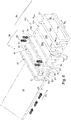
- Fig. 2 shows an example of a lamella 3 formed by bending forming. This has a plurality of corrugated roofs 31 and corrugated webs 32 which each follow one another in a first spatial direction (D1).
- the corrugated roofs 31 of the corrugated structure are as in FIG Fig. 11 shown, after the heat exchanger block 10 has been soldered in a soldering furnace, it is flatly connected to the respective adjacent partition plates 4 by a soldered connection.
- the lamellas 3 within the passages 1 fulfill three tasks: On the one hand, the heat exchange surface is enlarged by the fins. To optimize the heat transfer, the alignment of the wave-like structure in adjacent passages is selected depending on the application in such a way that equal, cross, counter or cross-counter flow is made possible between the adjacent passages.
- the lamellas with their corrugated roofs create a material connection under the metal dividers via the soldered connections.
- the corrugated webs of the lamellas absorb the forces that act on the separating plates due to the internal pressure.
- the lamellas serve to subdivide the passages into small channels, whereby a medium is evenly distributed over the entire width of a passage and thus the heat exchange between the media flowing in adjacent passages is improved.
- the lamella 3 Due to the boundary conditions to be observed during the forming process of the lamella 3, such as inner radii R2 and outer radii R1 of the sheet metal edges 34 ( Fig. 2 ) at the transition between the respective corrugated roof 31 and corrugated web 32 and the tolerances occurring during the forming process, the lamella 3 often has deviations from a desired ideal shape with regard to an ideal introduction of force. It has been shown that this limits the mechanical strength of a plate heat exchanger.
- the size of the outer radii R1 is determined by the size of the inner radii R2 and the wall thickness S of the lamella.
- the DE 103 43 107 A1 propose to manufacture the lamellas from a thick plate that is either hot-extruded or manufactured using a machining process in order to achieve a rectangular shape of corrugated roofs and corrugated webs.
- a machining shape is that when the heat exchanger block is soldered in the soldering furnace, the broken microstructure of the lamella created by the previous machining process takes up more solder, which disadvantageously reduces the strength of the lamella material.
- a lamella produced by hot extrusion can only have a narrowly limited width - in the DE 103 43 107 A1 Direction D2 shown - with a few corrugated roofs of about four to five. In addition, no perforated or cut geometries can be manufactured.
- a soldered plate heat exchanger according to the preamble of claim 1 is from the DE 103 43 107 A1 known.
- the object of the present invention is to provide a plate heat exchanger of the type mentioned at the outset which ensures high strength and can therefore be used for high pressure applications.
- the task is also to provide a method for its production.
- the outer radius of the sheet metal edge is between 0.05 mm and 0.18 mm and the inner radius of the sheet metal edge of the lamella is 0.2 to 0.4 mm.
- the outer radius of the sheet metal edge is preferably between 0.10 mm and 0.15 mm, particularly preferably between 0.10 mm and 0.12 mm. It has been shown that during the soldering process in the soldering furnace with an outer radius of the sheet metal edge in the areas defined above between the adjacent separating plate and the corrugated roof of the lamella, a fillet weld made of solder is formed in the area of the sheet metal edge, which enables optimal force transmission from the separating plate into the corrugated web enables.
- the sidebars are usually arranged between the dividing plates.
- the partition plates are generally flat partition plates made of sheet metal, which, like the lamella, are preferably formed from aluminum or an aluminum alloy.
- the outer radii are determined within the scope of the present invention by casting a lamella section with several corrugated roofs and corrugated webs in plastic and then separating it in a plane perpendicular to the corrugated roofs and corrugating webs and sanding the surface smooth.
- the outer radius of the sheet metal edge between the corrugated roof and corrugated web is then determined using a 3-point measuring process. For this purpose, three points are plotted on the smoothly ground cross-section of the sheet metal edge on the outer edge of the sheet metal edge and their position relative to one another is determined using a measuring device and a microscope. The outer radius is calculated from the two-dimensional coordinates of the three points.
- the inner radius of the sheet metal edge is preferably 0.3 mm.
- the inner radius of the sheet metal edge is determined in the same way as the above-described determination of the outer radius of the sheet metal edge. In contrast to the above procedure, the measuring points are applied to the inner edge of the sheet metal edge.
- the wall thickness of the lamella is preferably 0.2mm to 1.0mm.
- the corrugated roofs and the corrugated webs within a lamella have the same wall thickness in the area defined above.
- this means that the corrugated roofs and corrugated webs of the lamella preferably form straight wall sections with the same wall thickness, a corrugated roof in each case being connected to a corrugated web via a sharp-edged curved sheet metal edge.
- the lamella is preferably formed by forming a flat sheet of metal, preferably exclusively by forming in two or more forming process steps, preferably according to one or more forming processes described in DIN8582.
- the final forming process step is preferably pressure forming, in particular according to DIN8583, particularly preferably cold extrusion, in which the outer radii of the sheet metal edges are brought into the desired range defined above.
- the pressure forming preferably comprises neither bending nor drawing of the lamella material.
- the final pressure forming process step in particular the extrusion step, can be recognized by the fact that the structure has spherical grains, particularly in the area of the sheet metal edge in the transition from a corrugated roof to a corrugated web.
- the structure preferably has more than 50%, particularly preferably more than 80% and more preferably more than 95% grains of structure which have a spherical shape.
- the spherical grain structure can be demonstrated in a micrograph.
- lamellae that have been produced exclusively by bending or machining, have structures with elongated grain structures in the form of grains of rice.
- the reason for this is that flat-rolled metal sheets are used for bending and machining, which have this microstructure with elongated, grain-shaped grains even before bending and machining. These elongated grains can be stretched even further by bending.
- the surface of the lamella has an average roughness R a of less than 0.4 ⁇ m (micrometer), mostly in the range from 0.2 ⁇ m to 0.4 ⁇ m.
- R a average roughness
- the mean roughness R a indicates the mean distance of a measuring point - on the surface - to the center line.
- the center line intersects the real profile within the reference section in such a way that the sum of the profile deviations (in relation to the center line) is minimal.
- the mean roughness R a thus corresponds to the arithmetic mean of the absolute deviation from the center line.
- the lamella is preferably formed by a bending deformation step which is followed by a pressure deformation step.
- a - preferably flat - sheet metal is brought into a wave-shaped structure with at least one wave roof with wave webs.
- Bending forming within the scope of the present invention can comprise pure bending forming by pivoting about a bending axis, as well as pivoting about a bending axis with a drawing step in which the sheet metal is additionally drawn in one spatial direction.
- This is preferably followed by the pressure forming process step, preferably cold extrusion process step, in which the outer radius of the sheet metal edges formed during the bending process between the corrugated roof and corrugation web is reduced.
- the inner radius of the sheet metal edges preferably does not change in the final pressure forming process step.
- the corrugated roof and corrugated webs are rectangular, i. arranged at an angle of 90 ° with a deviation of preferably less than 1 °, particularly preferably less than 0.5 ° to one another.
- the corrugated webs of the lamella according to the invention are also arranged parallel to one another.
- the at least one corrugated roof has a planar, that is to say planar outer surface, in order to provide an optimal soldering connection surface to a separating plate in a plate heat exchanger.
- the lamellar roofs each have from one sheet metal edge to the adjacent sheet metal edge preferably a max. Deviation in their evenness of 0.02 mm.
- the lamella is preferably perforated and / or cut (the second is also referred to as “serrated") as in "
- the standards of the brazed aluminum plate-fin heat exchanger manufactures association "ALPEMA, Third Edition, 2010 on pages 9 and 10 shown and described.
- the lamella is advantageously made of aluminum or an aluminum alloy, particularly preferably an EN-AW 3003 alloy according to the European standard.
- An aluminum alloy according to the present invention accordingly has aluminum as the main component, preferably with a mass percentage of aluminum in the total alloy of at least 90% aluminum, particularly preferably at least 95% aluminum, and preferably less than 99.9% aluminum, particularly preferably from less than 99% aluminum.
- the mass fraction of aluminum in the aluminum alloy is particularly preferably in the range from 96.8% to 99%.
- Further alloy components can be one or more selected from the group: manganese, iron, copper or silicon.
- the manganese content of the aluminum alloy in % By mass is preferably in the range of 1.0% to 1.5% manganese.
- the iron content of the aluminum alloy in percentage by mass is preferably less than 0.7%.
- the mass percentage of copper in the aluminum alloy is preferably less than 0.2%.
- the aluminum alloy preferably has a silicon content in percent by mass of less than 0.5%, particularly preferably less than 0.1%.
- the solder layer between the partition plate and the corrugated roof of the lamella preferably covers more than 80%, preferably more than 90%, particularly preferably more than 95% of the cross-section of a corrugated web projected perpendicularly onto the partition plate with a constant solder layer thickness.
- the above solder cover geometries can be achieved and thus bursting pressures of the plate heat exchanger of more than 600 bar when using an EN-AW 3003 aluminum alloy for the lamella.
- All passages of the plate heat exchanger provided for the flow of media are preferably equipped with one or more of the fins described above.
- the plate heat exchanger moreover has the same components and the same structure as initially assigned Fig. 1 described.
- the plate heat exchanger according to the invention can also be used for a core-in-shell or block-in-kettle heat exchanger arrangement, as shown in " The standards of the brazed aluminum plate-fin heat exchanger manufactures association "ALPEMA, Third Edition, 2010, on pages 66 b is described and illustrated.
- the components such as cover plates, dividers and side strips of the plate heat exchanger are preferably made of aluminum or an aluminum alloy, as in particular in "
- the standards of the brazed aluminum plate-fin heat exchanger manufactures association "ALPEMA, Third Edition, 2010 on pages 45 and 46 described.
- the partition plates which can also be referred to as partition plates, preferably have a wall thickness in the range from 1.0 mm to 3.0 mm, particularly preferably from 1.2 to 2.5 mm and more particularly preferably from 1.4 to 1.7 mm on.
- the cover plates are usually designed with a greater wall thickness than the respective partition plates within the heat exchanger block.
- the cover plates point therefore preferably a wall thickness in the range from 3 to 12 mm, particularly preferably from 5 to 8 mm.
- solder layer between the partition plate and the corrugated roof of the lamella preferably covers more than 80%, particularly preferably more than 90%, of the cross-section of a corrugated web projected perpendicularly onto the partition plate with a constant solder layer thickness.
- This ensures that the pressure loads acting on the separating plates due to the media pressure during operation of the plate heat exchanger are optimally introduced over the entire width of the corrugated webs, whereby the maximum mechanical load capacity of the corrugated webs is exhausted. This enables bursting pressures of over 600 bar to be achieved.
- the lamella produced in this way has a high buckling strength. This allows thin-walled lamellas with wall thicknesses of less than 0.3mm in greater numbers are stacked on top of each other than before in the manufacturing process, thus increasing the number of passages in a plate heat exchanger and its height.
- the outer radius of the sheet metal edge which after a forming step according to step (a) is mostly in a range from 0.2mm to 1.6mm, often in a range from 0.4 to 1.4mm, is preferably used in step b) during pressure forming reduced to an outer radius in the range from 0.05mm to 0.18mm, particularly preferably 0.07mm to 0.18mm, more particularly preferably from 0.07mm to 0.12mm and more particularly preferably from 0.10mm to 0.12mm.
- the pressure forming according to step b) is a method for reshaping the provided wave-shaped structure, whereby a plastic state of at least part of the material is brought about, in particular in such a way that a relocation of material from the corrugated webs to the area of the sheet metal edges is made possible.
- a plastic state is thus preferably achieved, which enables a grain boundary shift within the material.
- the compressive stress during pressure forming can be uniaxial or multiaxial. Pressure forming according to DIN8583 is preferred.
- surface pressure is particularly preferably applied, preferably by a flat stamp, (preferably vertically) from the outside onto at least one corrugated roof, while more preferably the corrugated webs adjoining the corrugated roof are laterally fixed by a die and more preferably those on the second and third corrugated roofs adjacent to the corrugation webs are supported by a matrix.
- the die can be designed in one or more parts.
- the material of the body is brought to flow under a pressure - ie plastic deformation - which is preferably higher than the yield strength with 0.2% plastic deformation, which is also called R p0.2 [N / mm 2 ] is specified in material data sheets .
- This proof stress as R p0.2 [N / mm 2 ] can be determined in a tensile test according to ASTM B557M-15. A pressure of at least 80 N / mm 2 is therefore preferably applied to the material.
- a punch presses the body into or, if necessary, through a die.
- Cold extrusion is preferably used, in which no external heat is introduced into the material.
- the extrusion is carried out at ambient temperature, i.e. usually at temperatures below 50 ° C, especially below 40 ° C.
- Cold extrusion enables high dimensional accuracy.
- Both forward extrusion and reverse extrusion as well as transverse extrusion can be used. Any combinations of the extrusion processes mentioned can also be used.
- forward extrusion the material flow is directed in the effective direction of the punch, while in the case of backward extrusion, the material flow is directed against the effective direction of the punch.
- transverse extrusion the material flow is directed transversely to the effective direction of the punch.
- the at least one corrugated roof and the corrugated webs are arranged in a right-angled arrangement, i.e. brought into an angle of 90 ° with a deviation of preferably less than 1 °, particularly preferably less than 0.5 ° to each other, or if a right-angled arrangement already existed before the pressure forming, the corrugated roof and corrugated webs are kept in their right-angled arrangement.
- the corrugated roof and corrugated webs are usually not ideally arranged at right angles to one another, but have deviations of a few degrees - of up to 3 ° .
- the wave-shaped structure is preferably reduced in height.
- the height reduction is preferably in the range from 0.4 mm to 1.2 mm, particularly preferably in the range from 0.8 mm to 1.0 mm.
- the division preferably remains unchanged.
- the undulating structure provided in step a) can be obtained by reshaping a preferably flat sheet metal using a reshaping process known in the prior art.
- method step a) also preferably includes the prior production of the wave-shaped structure by a forming process. These are preferably a forming process in accordance with DIN 8582.
- the metal sheet is preferably formed by bending. This can include bending with straight tool movement, rotating tool movement, or a combination of both movements. In all three cases mentioned, the sheet metal is subjected to bending stress. A bending process according to DIN 8586 is preferred.
- This manufacturing process for the lamella has the advantage that the wall thickness of the corrugated webs is hardly changed in comparison to the wall thickness of the flat sheet metal as the starting material. This is of great importance for the strength of the lamella in the soldered connection with the separating plates of a plate heat exchanger.
- a lamella is obtained in which the wall thickness of the webs is only slightly reduced compared to the wall thickness of the flat sheet metal which forms the starting material.
- the percentage reduction in wall thickness is calculated using the following formula: ((S1-S2) / S1) * 100, where S1 is the wall thickness of the flat sheet metal as the starting material and S2 is the wall thickness of the corrugated web after pressure forming according to step (b).
- the percentage reduction in wall thickness is thus defined as the difference in wall thickness S2 (in Fig. 9 drawn) of the corrugated webs after pressure forming according to step b) and the wall thickness S1 of the flat sheet as the starting material (S1 in Fig.
- this reduction in wall thickness is less than 10%, particularly preferably less than 5% and more particularly preferably less than 1%. This cannot be achieved with conventional, exclusive bending processes for a lamella. With the exclusive bending process for a lamella, the reduction in wall thickness is usually at least 20%.
- the wall thickness of the lamella in the area of the pressure-formed sheet metal edge is advantageously increased compared to the wall thickness of the flat sheet metal as the starting material.
- the percentage increase in wall thickness in the area of the pressure-formed sheet edge is calculated using the following formula: ((S3-S1) / S1) * 100.
- S3 is the transverse wall thickness S3 ( Fig. 9 ) in the area of the pressure-formed bending edge and S1 ( Fig. 8 ) the wall thickness of the sheet metal, which is the starting material.
- This increase in wall thickness is thus defined as the difference between S3 and S1 divided by S1 multiplied by 100 to obtain the percentage Gain.
- the increase in wall thickness in the area of the pressure-formed sheet metal edge is preferably more than 1%, particularly preferably more than 5% and more particularly preferably more than 10%.
- an increase in wall thickness in the area of the sheet metal edge cannot be achieved.
- the exclusive bending processes according to the state of the art there is generally a reduction in the wall thickness of the lamella in the area of the bent sheet metal edge.
- the wave roof and wave web preferably alternate in a first spatial direction.
- the first spatial direction preferably coincides with the feed direction of the sheet metal when the sheet metal is being formed into the wave-like structure mentioned in step a).
- the wave-shaped structure is preferably also advanced in this first spatial direction.
- the direction of advance of the sheet metal during flat rolling to obtain a flat sheet metal prior to forming into the wave-shaped structure mentioned in step a) corresponds to the first spatial direction.
- the feed direction of the sheet metal during flat rolling is particularly preferably the same as the feed direction of the sheet metal during forming to the wave-shaped structure mentioned in step a) and the feed direction of the wave-shaped structure during pressure forming according to step b).
- the reshaping, preferably bending reshaping, mentioned in step a) of a sheet metal into a wave-shaped structure and the pressure reshaping according to step b) are preferably carried out in one device or in two or more devices arranged one behind the other. This makes it possible to process a sheet metal from a coil without interrupting the material between the forming mentioned in step a) and the pressure forming described in step b). This eliminates the need for intermediate storage of corrugated sheet metal. In the context of the invention, however, it is also possible to subject an already prefabricated sheet metal with a wave-shaped structure to pressure forming according to step b).
- the metal sheet is formed into a corrugated structure according to step a) and the pressure forming according to step b) without interrupting the flow of material, preferably in the same device, one after the other.
- the sheet metal is preferably first with at least one corrugated roof - i.e. a corrugated roof or, for example, 2 or 3 corrugated roofs - with respective corrugated webs formed into the wave-shaped structure, preferably by bending, and subsequently, preferably in the same feed direction as during the forming in step a), the at least one corrugated roof with corrugated webs according to step b) pressure-formed, preferably extruded.
- a wave consisting of a wave crest and adjoining wave webs, is preformed by bending and immediately afterwards pressure-molded before the next wave is formed.
- a feed of the sheet can take place between the forming of the first shaft according to step a) and the pressure forming of the first shaft according to step b) or there is no material feed, then this can take place between the forming of the first shaft and the second shaft.
- the lamella produced in this way has a higher buckling strength than lamellae that have been folded exclusively according to the prior art bending process.
- the separating plates and lamellas can be stacked in a higher stack without the lamellas in the lower passages being bent by the weight of the separating plates and lamellas lying above.
- the separating plates are preferably provided with a layer of solder, which is particularly preferably applied to the separating plates by plating.
- the plate heat exchanger according to the present invention can advantageously be used in the most varied of process sections in air separation plants, petrochemical plants, hydrogen plants, synthesis gas plants or natural gas plants.
- the plate heat exchanger can advantageously be used for applications in the temperature range of less than 80 ° C, preferably for cryogenic applications at temperatures in the range of 0 ° C to -270 ° C.
- FIG. 1 The plate heat exchanger according to Fig. 1 was already explained in the introductory part of the present description.
- a preferred embodiment of one Plate heat exchanger according to the invention has the same structure as in Fig. 1 but is associated with at least one of those generally described above or with respect to FIG Fig. 3 , 5 , 7th , 8th , 9 and 10 lamellas 103 described.
- Fig. 2 shows a lamella 3 according to the prior art, which is obtained by bending a flat metal sheet with the wall thickness S1.
- the lamella 3 has a wave-like structure with lower and upper wave roofs 31 which are connected to one another via wave webs 32.
- the corrugated roofs 31 and the corrugated webs 32 are connected by round bending edges 34, the bending edges 34 each having an outer radius R1 and an inner radius R2.
- the outer radius R1 of the bending edges 34 is determined by the inner radius R2 and the wall thickness S1.
- a first spatial direction D1 the corrugated roof 31 and the corrugated web 32 alternately follow one another.
- the height H1 of the lamella 3 extends in a second spatial direction D2, which is oriented perpendicular to the first spatial direction D1.
- a plurality of channels 36 extend in a third spatial direction D3, each of which is formed by a corrugated roof 31 with adjacent corrugated webs 32 and is delimited in a plate heat exchanger by separating plates 4 to which the lamella 3 is soldered ( Fig.11 ).
- a medium flows through the channels 36 in the spatial direction D3 (or in the opposite direction thereof).
- the third spatial direction D3 is aligned both perpendicular to the first spatial direction D1 and perpendicular to the second spatial direction D2.
- the pitch of the lamella 3 is indicated by the symbol "P1".
- the division P1 specifies the length of a structural section of the lamella 3 that is repeated in the first spatial direction D1. Here this is the distance from the wall center of a corrugated web 32 to the wall center of a subsequent corrugated web 32.
- the present lamella 3 has a relatively small pitch P1 with a relatively large wall thickness S1 and thus a relatively large outer radius R1. As a result, only a relatively small portion of the outer surface 35 of a corrugated roof 31 is flat.
- Fig. 3 Figure 10 shows a lamella 103 according to an embodiment of the present invention. This was formed by a manufacturing process, which a Includes bending forming step with subsequent pressure forming step. The manufacturing process is related to Fig. 8 explained in more detail below.
- the lamella 103 according to Fig. 3 has a sharp-edged, undulating structure with corrugated roofs 131 and corrugated webs 132 which alternate in the first spatial direction D1.
- the lower and upper corrugated roofs 131 are flat and each run parallel to one another, ie with a maximum deviation of 1 °, preferably 0.5 °.
- the corrugated webs 132 are each arranged at right angles to the corrugated roofs 131. Therefore, the corrugated webs 132, which extend in the second spatial direction D2, each run parallel to one another, ie with a maximum deviation of 1 °, preferably 0.5 °.
- the corrugated roofs 131 are each connected to the corrugated webs 132 via sharp-edged sheet metal edges 134.
- the sheet metal edges 134 each have an outer radius R101 and an inner radius R102.
- the inner radii are preferably 0.2 mm to 0.4 mm and the outer radii according to the invention are 0.05 mm to 0.18 mm.
- the division is specified with P101 and is usually 0.9mm to 5.0mm.
- the height H101 of the lamella 103 can be 4.0mm to 12mm.
- the wall thickness S101 can be in the range from 0.2mm to 1.0mm.
- the sharp-edged contour of the sheet metal edges 134 with outer radii R101 less than 0.2 mm is achieved by a pressure forming step in which the flexurally formed lamella 3 is formed Fig. 2 is mainly compressed in the direction of the second spatial direction D2 and is thus reduced in height to a height 101.
- the height reduction is usually between 0.8mm and 1.2mm.
- the corrugated roofs 131 have flat outer surfaces 135 over their entire width (width running in the first spatial direction D1), apart from the surface areas that are curved due to the outer radii R101, for optimal connection by soldering with likewise flat, in Figures 9 and 10 partitions 4 shown.
- Fig. 8 shows an embodiment of a manufacturing method for the in Fig. 3
- the starting material for the production of the lamella 103 according to the invention is a flat, smooth metal sheet 20, for example made of an aluminum alloy according to European standard EN-AW-3003 with a material thickness or wall thickness S1.
- the sheet metal 20 is preferably unwound from a sheet metal coil, not shown.
- the flat metal sheet 20 is obtained by flat rolling a cast ingot.
- the structure of the metal sheet 20 therefore has elongated grains 21, as in FIG Fig. 12 shown schematically.
- a first step (a) of the manufacturing method according to the invention the flat metal sheet 20 shown in the left section of the figure is bent into a corrugated structure with one, two or more corrugated roofs 31 with respective adjoining corrugated webs 32, as in Fig. 2 shown and described above, brought.
- one or more tools preferably act vertically on the sheet metal 20 from below and / or above in a straight movement.
- Slide bending is preferred.
- the direction of advance D1 of the sheet metal 20 during slide-draw bending, which is shown with arrows, corresponds to that in FIG Fig. 2 indicated spatial direction D1.
- the bending can also be done by rotating the tool or by a combination of straight and rotating tool movements.
- the bending process is preferably carried out using a method described in DIN 8586.
- the structure ( Fig. 12 ) the bent lamella 3 has, after the bending according to step (a), elongated, rice-grain-shaped grains 21, as does the sheet metal 20, which forms the starting material.
- the grains of the structure can also have curvatures, but this is not shown.
- the bending deformation also includes a drawing portion, then the grains 21 can be stretched further compared to the structure present in the sheet metal 20, ie they can have a greater length, which is, however, also not shown.
- the feed direction when the sheet metal 20 is rolled flat preferably coincides with the spatial direction D1 and thus with the feed direction D1 during bending according to step (a).
- the round wave-shaped structure 3 formed in the first step (a), which is shown in the central figure section of FIG Fig. 8 is shown, in a second step (b) of the production method according to the invention, further deformation is carried out by pressure deformation.
- a surface pressure is applied vertically from the outside to the outer surface 35 of one or more corrugated roofs 31 of the wave-shaped structure, for example with the aid of a flat stamp (illustrated by the arrows 50).
- the respective shaft made up of the shaft roof 31 and adjacent shaft webs 32 is fixed in a die, not shown.
- the structure of the pressure-formed lamella 103 has spherical structure grains 121, as in FIG Fig. 13 shown schematically on.
- the lamella 103 produced in this way has a surface with an average roughness Ra of less than 0.4 ⁇ m.
- the outer radius R101 (back to Fig. 8 ) after the pressure forming step is below 0.18 mm, particularly preferably below 0.15 mm.
- the feed direction during pressure forming takes place in the spatial direction D1, as with bending forming.
- the pressure forming of the wave-like structure accordingly takes place mainly in the spatial direction D2.
- the bending-forming step (a) and the pressure-forming step (b) take place one after the other, preferably without interrupting the material flow in the same device.
- Result of the manufacturing process according to Fig. 8 is the in Fig. 3 Lamella 103 already described above.
- the fin 103 becomes for the manufacture of a plate heat exchanger as above Fig. 1 used. Instead of the in Fig. 1 Slats provided with the reference numbers 2 and 3 become slats 103 according to FIG Fig. 3 used.
- Separating plates 4 soldered on both sides are alternately arranged with lamellae 103 and edge strips 8 with outer cover plates 5 in a stack and soldered in a soldering furnace. Then headers 7 with connecting pieces 6 are welded onto the soldered heat exchanger block.
- Fig. 9 shows a cross section through a lamella 103 with adjacent, soldered partition plates 4.
- Fig. 10 shows a detail Y from Fig. 9 . It can be seen from both figures that a solder layer 140 with a constant thickness d is formed between the corrugated roofs 131 and the separating plates 4, which 100% covers the cross-section Q of the adjacent corrugated web projected perpendicularly onto the separating plate 4. As a result, the forces acting on the separating plates 4 due to the internal pressure can be transferred via the solder layer 140 into the corrugated webs 132 over their entire Cross-section Q can be introduced vertically.
- a fillet weld 141 is formed with an outer radius R101 in the range according to the invention from 0.05 mm to 0.18 mm outside the projected corrugation cross-section Q, as a result of which the aforementioned optimal solder layer cover geometry is achieved.
- the wall thickness of the pressure-formed lamella 103 in the area of the web 132 is indicated by the reference number S2.
- the wall thickness S2 of the webs 132 is only slightly reduced compared to the wall thickness S1 ( Fig. 8 ) of the flat sheet metal 20, which is the starting material.
- the percentage reduction in wall thickness is calculated as follows: ((S1-S2) / S1) * 100. This is less than 10%, particularly preferably less than 5% and more particularly preferably less than 1%. This cannot be achieved with conventional bending processes for a lamella. In the case of the exclusively bend-formed lamellae according to the prior art, the percentage reduction in wall thickness is generally at least 20%.
- a transverse wall thickness in the area of the pressure-formed sheet metal edge 134 is entered with the reference number S3.
- the transverse wall thickness S3 in the area of the sheet metal edge 134 is compared to the wall thickness S1 ( Fig. 8 ) of the flat sheet metal 20, which is the starting material, is enlarged.
- the percentage increase in wall thickness is calculated as follows: ((S3-S1) / S1) * 100. This is preferably more than 1%, particularly preferably more than 5% and more particularly preferably more than 10%. This cannot be achieved with conventional bending processes for a lamella. As a rule, there is a reduction in the wall thickness of the lamella in the area of an exclusively bent sheet metal edge.
- Fig. 11 shows the soldering of an exclusively bend-formed lamella 3 according to FIG Fig. 2 and thus according to the state of the art.
- the fillet weld 41 which is formed during soldering between the bending edge 34 having an outer radius R1 and the separating plate 4, lies in the area of the projected corrugation cross-section Q.
- the projected cross-section Q no solder layer of constant thickness is formed.
- the fillet weld 41 moreover does not bridge the entire projected cross section Q of the corrugated web 32: surface areas F of the corrugated webs 32 are not connected to the separating plates 4 via a closed solder layer.
- Such a soldered connection has proven to be disadvantageous for the strength of the plate heat exchanger.
- Fig. 4 shows a bent, cut lamella 3 after step (a) ( Fig. 8 ) of the method according to the invention and thus according to the prior art.
- This is produced by slide bending of a flat metal sheet with a superimposed, simultaneous cut through mutually offset individual punches.
- the offset is in direction D1 and alternates over the entire sheet width in direction D3.
- the cutting length L is between 1.5 mm and 50 mm.
- a subsequent pressure forming step (b) according to the invention according to the invention (according to Fig. 8 ), the result of which is in Fig. 5 is shown, the round undulating structure of Fig. 4 into a sharp-edged, wavy structure of Fig. 5 transferred, in which the outer radius of the bending edge is reduced from R1 to R101, preferably to 0.05mm to 0.18mm.
- Fig. 6 shows a bent, perforated lamella 3 after step (a) ( Fig. 8 ) of the method according to the invention and thus according to the prior art.
- the perforations (holes 50) are usually spaced between 2 mm and 30 mm and have a diameter in the range of 1 mm and 3 mm.
- a subsequent pressure forming step (b) according to Fig. 8
- the result of which is in Fig. 7 is shown, the round, undulating structure of Fig. 6 into a sharp-edged structure of Fig. 7 transferred, in which the outer radius of the bending edge is reduced from R1 to R101 to 0.05mm to 0.18mm.
- the lamella 103 according to Fig. 3 , 5 and 7th can be produced with the described method in a width (in direction D3) of, for example, 450mm and a length (in direction D1) of 1500mm.
- Heat exchanger block 10 first spatial direction D1 second spatial direction D2 third spatial direction D3 metal sheet 20th
- Corrugated bridge 32 Bending edge 34 Corrugated roof outer surface 35 channel 36
Description
Die vorliegende Erfindung betrifft einen gelöteten Plattenwärmetauscher mit einer Mehrzahl von in einem Stapel und mit Abstand zueinander angeordneter Trennbleche, die Passagen für zumindest zwei in indirekten Wärmeaustausch tretende Fluide bilden, wobei zumindest eine Passage eine Lamelle aus Aluminium oder einer Aluminiumlegierung aufweist. Des Weiteren bezieht sich die vorliegende Erfindung auf ein Verfahren zur Herstellung eines derartigen Plattenwärmetauschers.The present invention relates to a soldered plate heat exchanger with a plurality of separating plates arranged in a stack and at a distance from one another, which form passages for at least two fluids entering into indirect heat exchange, at least one passage having a lamella made of aluminum or an aluminum alloy. The present invention also relates to a method for producing such a plate heat exchanger.
Gelötete Plattenwärmetauscher aus Aluminium werden in zahlreichen Anlagen bei verschiedensten Drücken und Temperaturen eingesetzt. Sie finden beispielsweise Anwendung bei der Zerlegung von Luft, der Verflüssigung von Erdgas oder in Anlagen zur Herstellung von Ethylen.Brazed plate heat exchangers made of aluminum are used in numerous systems at various pressures and temperatures. They are used, for example, in the separation of air, the liquefaction of natural gas or in plants for the production of ethylene.
Ein gelöteter Plattenwärmetauscher wird beispielsweise in "
Der dort gezeigte Plattenwärmetauscher umfasst mehrere in einem Stapel mit Abstand zueinander angeordnete Trennbleche 4, die eine Vielzahl von Passagen 1 für die miteinander in Wärmeaustausch zu bringenden Medien bilden. Die Passagen 1 sind durch bündig am Rand der Trennbleche 4 angebrachte Randleisten 8, im Englischen auch als Sidebars 8 bezeichnet, nach außen abgeschlossen. Innerhalb der Passagen 1 sind Lamellen 3 mit wellenförmiger Struktur, im Englischen auch als Fins bezeichnet, angeordnet. Die Trennbleche 4, Lamellen 3 und Randleisten 8 sind durch Löten miteinander verbunden und bilden somit einen kompakten Wärmetauscherblock 10. Der gesamte Wärmetauscherblock 10 ist durch Deckbleche 5 nach außen begrenzt.The plate heat exchanger shown there comprises a plurality of separating
Zur Zu- und Abführung der wärmeaustauschenden Medien sind über Eintritts- und Austrittsöffnungen 9 der Passagen 1 halbzylinderförmige Sammler 7 mit Stutzen 6 angebracht, die zum Anschluss von zu- und abführenden Rohrleitungen dienen. Die Sammler 7 werden im Folgenden auch als Header 7 bezeichnet. Die Ein-und Austrittsöffnungen 9 der Passagen 1 sind durch sogenannte Verteilerlamellen bzw.To supply and discharge the heat-exchanging media,
Verteilerfins 2 gebildet, die für eine gleichmäßige Verteilung der Medien über die gesamte Breite der einzelnen Passagen 1 sorgen. Die Medien strömen in den durch die Lamellen 3 und die Trennbleche 4 gebildeten Kanälen durch die Passagen 1.
Derartige Plattenwärmetauscher sind vorzugsweise aus Aluminium gebildet. Die zum Teil mit Lot versehenen Lamellen 3, Trennbleche 4, Verteilerlamellen 2, Deckbleche 5 und Randleisten 8 werden in Form eines quaderförmigen Blockes aufeinander gestapelt und anschließend in einem Ofen zu einem Wärmetauscherblock 10 gelötet. Im Allgemeinen wird das Lot vor dem Verlöten beidseitig auf die Trennbleche und ggf. auf die Lamellen aufgebracht. Nach dem Verlöten in einem Lötofen werden auf den Wärmetauscherblock 10 die Sammler 7 mit Stutzen 6 aufgeschweißt.Such plate heat exchangers are preferably formed from aluminum. The
Die Lamellen werden im Allgemeinen aus dünnen, ebenen Blechen hergestellt, welche mit einer Presse oder anderen zum Biegeumformen geeigneten Werkzeugen zu wellenförmigen Strukturen gefaltet werden.
Die Lamellen 3 innerhalb der Passagen 1 erfüllen drei Aufgaben:
Zum einen wird durch die Lamellen die Wärmeaustauschfläche vergrößert. Zur Optimierung der Wärmeübertragung wird die Ausrichtung der wellenförmigen Struktur in benachbarten Passagen in Abhängigkeit vom Anwendungsfall so gewählt, dass Gleich- Kreuz-, Gegen- oder Kreuz-Gegenströmung zwischen den benachbarten Passagen ermöglicht wird.The
On the one hand, the heat exchange surface is enlarged by the fins. To optimize the heat transfer, the alignment of the wave-like structure in adjacent passages is selected depending on the application in such a way that equal, cross, counter or cross-counter flow is made possible between the adjacent passages.
Zum anderen stellen die Lamellen mit ihren Wellendächern über die Lötverbindungen eine stoffschlüssige Verbindung unter den Trennblechen her. Die Wellenstege der Lamellen nehmen die Kräfte auf, die durch den Innendruck auf die Trennbleche wirken.On the other hand, the lamellas with their corrugated roofs create a material connection under the metal dividers via the soldered connections. The corrugated webs of the lamellas absorb the forces that act on the separating plates due to the internal pressure.
Zudem dienen die Lamellen dazu, die Passagen in kleine Kanäle zu unterteilen, wodurch eine gleichmäßige Verteilung eines Mediums über die gesamte Breite einer Passage erreicht wird und somit der Wärmetausch zwischen den in benachbarten Passagen fließenden Medien verbessert wird.In addition, the lamellas serve to subdivide the passages into small channels, whereby a medium is evenly distributed over the entire width of a passage and thus the heat exchange between the media flowing in adjacent passages is improved.
Durch die bei dem Umformprozess der Lamelle 3 einzuhaltenden Randbedingungen, wie Innenradien R2 und Außenradien R1 der Blechkanten 34 (
Um die mechanische Festigkeit eines Plattenwärmeaustauschers mit Lamellen zu verbessern, schlägt die
In der
Aufgabe der vorliegenden Erfindung ist, einen Plattenwärmetauscher der eingangs genannten Art zur Verfügung zu stellen, welcher eine hohe Festigkeit gewährleistet und damit für Hochdruckanwendungen einsetzbar ist. Aufgabe ist auch die Bereitstellung eines Verfahrens zu dessen Herstellung.The object of the present invention is to provide a plate heat exchanger of the type mentioned at the outset which ensures high strength and can therefore be used for high pressure applications. The task is also to provide a method for its production.
Diese Aufgabe wird gelöst mit einem gelöteten Plattenwärmetauscher mit den Merkmalen nach Anspruch 1 und einem Verfahren zur Herstellung des Plattenwärmetauschers nach Anspruch 7.This object is achieved with a soldered plate heat exchanger having the features according to claim 1 and a method for producing the plate heat exchanger according to
Demnach wird ein gelöteter Plattenwärmetauscher bereitgestellt mit einer Mehrzahl von in einem Stapel und mit Abstand zueinander angeordneter Trennplatten, die Passagen für zumindest zwei in indirekten Wärmeaustausch tretende Fluide bilden, wobei zumindest eine Passage eine Lamelle (oder ggf. mehrere Lamellen) aus Aluminium oder einer Aluminiumlegierung aufweist, wobei die Lamelle eine wellenförmige Struktur aus einem Blech aufweist:
- mit parallel zueinander angeordneten Wellendächern, wobei ein Wellendach über einen Wellensteg mit einem weiteren Wellendach verbunden ist,
- wobei in einer ersten Raumrichtung Wellendach und Wellensteg aufeinander folgen,
- wobei Wellendach und Wellensteg durch eine Blechkante miteinander verbunden sind,
- wobei jede Blechkante einen Innenradius und einen Außenradius aufweist, und
- wobei die Wellendächer eine plane Außenfläche aufweisen.
- with corrugated roofs arranged parallel to one another, one corrugated roof being connected to another corrugated roof via a corrugated web,
- whereby in a first spatial direction the corrugated roof and corrugated web follow one another,
- whereby the corrugated roof and corrugated web are connected to one another by a sheet metal edge,
- each sheet metal edge having an inner radius and an outer radius, and
- wherein the corrugated roofs have a flat outer surface.
Erfindungsgemäß betragen der Außenradius der Blechkante zwischen 0,05mm und 0,18mm und der Innenradius der Blechkante der Lamelle 0,2 bis 0,4mm. Vorzugsweise beträgt der Außenradius der Blechkante zwischen 0,10mm und 0,15mm, besonders bevorzugt zwischen 0,10mm und 0,12mm. Es hat sich gezeigt, dass sich während des Lötvorgangs im Lötofen bei einem Außenradius der Blechkante in den oben definierten Bereichen zwischen dem benachbarten Trennblech und dem Wellendach der Lamelle eine Kehlnaht aus Lot im Bereich der Blechkante ausgebildet, die eine optimale Krafteinleitung vom Trennblech in den Wellensteg ermöglicht.According to the invention, the outer radius of the sheet metal edge is between 0.05 mm and 0.18 mm and the inner radius of the sheet metal edge of the lamella is 0.2 to 0.4 mm. The outer radius of the sheet metal edge is preferably between 0.10 mm and 0.15 mm, particularly preferably between 0.10 mm and 0.12 mm. It has been shown that during the soldering process in the soldering furnace with an outer radius of the sheet metal edge in the areas defined above between the adjacent separating plate and the corrugated roof of the lamella, a fillet weld made of solder is formed in the area of the sheet metal edge, which enables optimal force transmission from the separating plate into the corrugated web enables.
Durch zwischen den Trennplatten in der Regel angeordneten Seitenleisten (im Englischen: Sidebars) sind die Passagen seitlich begrenzt. Bei den Trennplatten handelt es sich im Allgemeinen um ebene Trennplatten aus Blech, die vorzugsweise wie die Lamelle aus Aluminium oder einer Aluminiumlegierung gebildet sind.The sidebars are usually arranged between the dividing plates. The partition plates are generally flat partition plates made of sheet metal, which, like the lamella, are preferably formed from aluminum or an aluminum alloy.
Die Bestimmung der Außenradien erfolgt im Rahmen der vorliegenden Erfindung, indem ein Lamellenabschnitt mit mehreren Wellendächern und Wellenstegen in Kunststoff eingegossen und anschließend in einer Ebene senkrecht zu den Wellendächern und Wellenstegen aufgetrennt und oberflächlich glatt geschliffen wird. Mithilfe eines 3-Punkt Messverfahrens wird anschließend der Außenradius der Blechkante zwischen Wellendach und Wellensteg ermittelt. Hierzu werden drei Punkte auf dem glatt geschliffenen Querschnitt der Blechkante am Außenrand der Blechkante angetragen und deren Position zueinander mithilfe einer Messeinrichtung und einem Mikroskop ermittelt. Aus den ermittelten zweidimensionalen Koordinaten der drei Punkte wird der Außenradius rechnerisch ermittelt.The outer radii are determined within the scope of the present invention by casting a lamella section with several corrugated roofs and corrugated webs in plastic and then separating it in a plane perpendicular to the corrugated roofs and corrugating webs and sanding the surface smooth. The outer radius of the sheet metal edge between the corrugated roof and corrugated web is then determined using a 3-point measuring process. For this purpose, three points are plotted on the smoothly ground cross-section of the sheet metal edge on the outer edge of the sheet metal edge and their position relative to one another is determined using a measuring device and a microscope. The outer radius is calculated from the two-dimensional coordinates of the three points.
Der Innenradius der Blechkante beträgt bevorzugt 0,3mm.The inner radius of the sheet metal edge is preferably 0.3 mm.
Die Bestimmung des Innenradius der Blechkante erfolgt in gleicher Weise wie die vorstehend beschriebene Bestimmung des Außenradius der Blechkante. Im Unterschied zu obigem Verfahren werden die Messpunkte auf den Innenrand der Blechkante aufgetragen.The inner radius of the sheet metal edge is determined in the same way as the above-described determination of the outer radius of the sheet metal edge. In contrast to the above procedure, the measuring points are applied to the inner edge of the sheet metal edge.
Die Wandstärke der Lamelle, und somit die Wandstärke der Wellendächer und der Wellenstege, beträgt vorzugsweise 0,2mm bis 1,0mm. Vorzugsweise weisen die Wellendächer und die Wellenstege innerhalb einer Lamelle eine gleiche Wandstärke im oben definierten Bereich auf. In anderen Worten bedeutet dies, dass die Wellendächer und Wellenstege der Lamelle vorzugsweise gerade Wandabschnitte mit gleicher Wandstärke bilden, wobei jeweils ein Wellendach über eine scharfkantig gekrümmte Blechkante mit einem Wellensteg verbunden ist.The wall thickness of the lamella, and thus the wall thickness of the corrugated roofs and the corrugated webs, is preferably 0.2mm to 1.0mm. Preferably, the corrugated roofs and the corrugated webs within a lamella have the same wall thickness in the area defined above. In other words, this means that the corrugated roofs and corrugated webs of the lamella preferably form straight wall sections with the same wall thickness, a corrugated roof in each case being connected to a corrugated web via a sharp-edged curved sheet metal edge.
Vorzugsweise ist die Lamelle durch Umformen eines ebenen Metallbleches gebildet, vorzugsweise ausschließlich durch Umformen in zwei oder mehreren Umformverfahrensschritten, bevorzugt nach einem oder mehreren in DIN8582 beschriebenen Umformverfahren.The lamella is preferably formed by forming a flat sheet of metal, preferably exclusively by forming in two or more forming process steps, preferably according to one or more forming processes described in DIN8582.
Abschließender Umformverfahrensschritt ist vorzugsweise ein Druckumformen insbesondere nach DIN8583, besonders bevorzugt ein kaltes Fließpressen, bei welchem die Außenradien der Blechkanten in den gewünschten, oben definierten Bereich gebracht werden.The final forming process step is preferably pressure forming, in particular according to DIN8583, particularly preferably cold extrusion, in which the outer radii of the sheet metal edges are brought into the desired range defined above.
Vorzugsweise umfasst das Druckumformen weder ein Biegen noch ein Ziehen des Lamellenmaterials. Bei der erfindungsgemäßen Lamelle ist der abschließende Druckumformverfahrensschritt, insbesondere Fließpressschritt, dadurch erkennbar, dass das Gefüge insbesondere im Bereich der Blechkante im Übergang von einem Wellendach zu einem Wellensteg kugelförmige Körner aufweist. Vorzugsweise weist das Gefüge zu mehr als 50%, besonders bevorzugt zu mehr als 80% und weiter bevorzugt zu mehr als 95% Gefügekörner auf, die eine Kugelform besitzen. Die kugelförmige Körnerstruktur ist in einem Gefügeschliffbild nachweisbar.The pressure forming preferably comprises neither bending nor drawing of the lamella material. In the lamella according to the invention, the final pressure forming process step, in particular the extrusion step, can be recognized by the fact that the structure has spherical grains, particularly in the area of the sheet metal edge in the transition from a corrugated roof to a corrugated web. The structure preferably has more than 50%, particularly preferably more than 80% and more preferably more than 95% grains of structure which have a spherical shape. The spherical grain structure can be demonstrated in a micrograph.
Im Vergleich hierzu weisen Lamellen, die ausschließlich durch ein Biegeumformen oder eine spanabhebende Fertigung hergestellt wurden, Gefüge mit langgestreckten, reiskornförmigen Körnerstrukturen auf. Grund hierfür ist, dass zum Biegeumformen und zur spanabhebenden Fertigung flachgewalzte Bleche eingesetzt werden, die diese Gefügestruktur mit langgestreckten, reiskornförmigen Körnern bereits vor dem Biegeumformen und der spanabhebenden Fertigung aufweisen. Durch Biegeumformen können diese langgestreckten Körner noch weiter gestreckt sein.In comparison to this, lamellae that have been produced exclusively by bending or machining, have structures with elongated grain structures in the form of grains of rice. The reason for this is that flat-rolled metal sheets are used for bending and machining, which have this microstructure with elongated, grain-shaped grains even before bending and machining. These elongated grains can be stretched even further by bending.
In der Regel weist die Oberfläche der Lamelle, nach dem Druckumformschritt eine mittlere Rauigkeit Ra von weniger als 0,4µm (Mikrometer) auf, meist liegt sie im Bereich von 0,2µm bis 0,4µm. Diese Oberflächenrauheitswerte sind bedingt durch das Werkzeug, das bei dem erfindungsgemäßen Druckumformen eingesetzt wird. Die Oberflächenrauheitswerte der auf die Lamelle einwirkenden Werkzeugoberfläche, beispielsweise eines Stempels, werden beim Druckumformen auf die Lamelle übertragen.As a rule, after the pressure forming step, the surface of the lamella has an average roughness R a of less than 0.4 µm (micrometer), mostly in the range from 0.2 µm to 0.4 µm. These surface roughness values are due to the tool that is used in the pressure forming according to the invention. The surface roughness values of the tool surface acting on the lamella, for example a punch, are transferred to the lamella during pressure forming.
Die mittlere Rauheit Ra gibt den mittleren Abstand eines Messpunktes - auf der Oberfläche - zur Mittellinie an. Die Mittellinie schneidet innerhalb der Bezugsstrecke das wirkliche Profil so, dass die Summe der Profilabweichungen (bezogen auf die Mittellinie) minimal wird. Die mittlere Rauheit Ra entspricht also dem arithmetischen Mittel der betragsmäßigen Abweichung von der Mittellinie. Mithilfe des abschließenden Druckumformverfahrensschritts ist die mittlere Rauheit der Lamellenoberfläche reduziert gegenüber der Oberfläche einer Lamelle, die ausschließlich durch Biegeumformen mit oder ohne Ziehen des Materials gefertigt ist. Die mittlere Rauheit Ra der Oberfläche von durch Biegeumformen gebildeten Lamellen liegt bei etwa 10µm.The mean roughness R a indicates the mean distance of a measuring point - on the surface - to the center line. The center line intersects the real profile within the reference section in such a way that the sum of the profile deviations (in relation to the center line) is minimal. The mean roughness R a thus corresponds to the arithmetic mean of the absolute deviation from the center line. With the help of the final pressure forming process step, the mean roughness of the lamella surface is reduced compared to the surface of a lamella, which is produced exclusively by bending with or without drawing the material. The mean roughness R a of the surface of lamellae formed by bending is around 10 μm.
Vorzugsweise ist die Lamelle gebildet durch einen Biegeumformschritt, an den sich ein Druckumformschritt anschließt. Bei dem Biegeumformschritt, vorzugsweise nach DIN8586, wird ein - vorzugsweise ebenes - Metallblech in eine wellenförmige Struktur mit mindestens einem Wellendach mit Wellenstegen gebracht.The lamella is preferably formed by a bending deformation step which is followed by a pressure deformation step. In the bending forming step, preferably after DIN8586, a - preferably flat - sheet metal is brought into a wave-shaped structure with at least one wave roof with wave webs.
Ein Biegeumformen im Rahmen der vorliegenden Erfindung kann ein reines Biegeumformen durch Schwenken um eine Biegeachse umfassen, als auch ein Schwenken um eine Biegeachse mit einem Ziehformschritt, bei welchem das Blech zusätzlich in eine Raumrichtung gezogen wird. Daran schließt sich vorzugsweise der Druckumformverfahrensschritt, vorzugsweise kalte Fließpressverfahrensschritt an, bei welchem der Außenradius der beim biegeumformen gebildeten Blechkanten zwischen Wellendach und Wellensteg reduziert wird. Der Innenradius der Blechkanten verändert sich bei dem abschließenden Druckumformverfahrensschritt vorzugsweise nicht. Das weiter bevorzugte Herstellverfahren wird nachstehend noch näher erläutert.Bending forming within the scope of the present invention can comprise pure bending forming by pivoting about a bending axis, as well as pivoting about a bending axis with a drawing step in which the sheet metal is additionally drawn in one spatial direction. This is preferably followed by the pressure forming process step, preferably cold extrusion process step, in which the outer radius of the sheet metal edges formed during the bending process between the corrugated roof and corrugation web is reduced. The inner radius of the sheet metal edges preferably does not change in the final pressure forming process step. The further preferred production process is explained in more detail below.
Vorzugsweise sind bei der Lamelle Wellendach und Wellenstege rechtwinklig, d.h. in einem Winkel von 90° mit einer Abweichung von vorzugsweise weniger als 1°, besonders bevorzugt von weniger als 0,5° zueinander angeordnet. Hieraus folgt, dass auch die Wellenstege der erfindungsgemäßen Lamelle parallel zueinander angeordnet sind. Zudem weist das mindestens eine Wellendach eine plane, also ebene Außenfläche auf, um eine optimale Löt-Verbindungsfläche zu einem Trennblech in einem Plattenwärmetauscher bereitzustellen. Die Lamellendächer weisen jeweils von einer Blechkante zur benachbarten Blechkante vorzugsweise eine max. Abweichung in ihrer Ebenheit von 0,02 mm auf.Preferably, in the lamella, the corrugated roof and corrugated webs are rectangular, i. arranged at an angle of 90 ° with a deviation of preferably less than 1 °, particularly preferably less than 0.5 ° to one another. It follows from this that the corrugated webs of the lamella according to the invention are also arranged parallel to one another. In addition, the at least one corrugated roof has a planar, that is to say planar outer surface, in order to provide an optimal soldering connection surface to a separating plate in a plate heat exchanger. The lamellar roofs each have from one sheet metal edge to the adjacent sheet metal edge preferably a max. Deviation in their evenness of 0.02 mm.
Vorzugsweise ist die Lamelle perforiert und/oder geschnitten (zweites im Englischen auch als "serrated" bezeichnet) ausgeführt wie in "
Vorzugsweise deckt bei dem Plattenwärmetauscher die Lotschicht zwischen Trennblech und Wellendach der Lamelle zu mehr als 80%, bevorzugt zu mehr 90%, besonders bevorzugt zu mehr als 95% den senkrecht auf das Trennblech projizierten Querschnitt eines Wellenstegs mit gleichbleibender Lotschichtdicke ab.In the plate heat exchanger, the solder layer between the partition plate and the corrugated roof of the lamella preferably covers more than 80%, preferably more than 90%, particularly preferably more than 95% of the cross-section of a corrugated web projected perpendicularly onto the partition plate with a constant solder layer thickness.
Mit der Lamelle können obige Lot-Abdeckungsgeometrien erreicht werden und damit Berstdrücke des Plattenwärmetauschers von mehr als 600 bar bei Verwendung einer EN-AW 3003 Aluminium-Legierung für die Lamelle realisiert werden.With the lamella, the above solder cover geometries can be achieved and thus bursting pressures of the plate heat exchanger of more than 600 bar when using an EN-AW 3003 aluminum alloy for the lamella.
Vorzugsweise sind alle für den Mediendurchfluss vorgesehenen Passagen des Plattenwärmetauschers mit einer oder mehreren der vorstehend beschriebenen Lamellen ausgestattet. Dabei weist der Plattenwärmetauscher in einer bevorzugten Ausführungsform im Übrigen die gleichen Bauteile und den denselben Aufbau auf wie eingangs zu
Der erfindungsgemäße Plattenwärmetauscher kann auch für eine Core-in-Shell bzw. Block-in-Kettle - Wärmetauscheranordnung eingesetzt werden, wie sie in "
Vorzugsweise sind die Bauteile wie Deckbleche, Trennbleche und Seitenleisten des Plattenwärmetauschers aus Aluminium oder einer Aluminiumlegierung gebildet, wie insbesondere in "
Die Trennbleche, die auch als Trennplatten bezeichnet werden können, weisen vorzugsweise eine Wandstärke im Bereich von 1,0mm bis 3,0 mm, besonders bevorzugt von 1,2 bis 2,5 mm und weiter besonders bevorzugt von 1,4 bis 1,7 mm auf. Die Deckbleche sind in der Regel mit einer größeren Wandstärke ausgeführt wie die jeweiligen Trennbleche innerhalb des Wärmetauscherblocks. Die Deckbleche weisen daher vorzugsweise eine Wandstärke im Bereich von 3 bis 12 mm, besonders bevorzugt von 5 bis 8 mm auf.The partition plates, which can also be referred to as partition plates, preferably have a wall thickness in the range from 1.0 mm to 3.0 mm, particularly preferably from 1.2 to 2.5 mm and more particularly preferably from 1.4 to 1.7 mm on. The cover plates are usually designed with a greater wall thickness than the respective partition plates within the heat exchanger block. The cover plates point therefore preferably a wall thickness in the range from 3 to 12 mm, particularly preferably from 5 to 8 mm.
Die vorliegende Patentanmeldung stellt auch ein Verfahren zur Herstellung eines vorstehend beschriebenen Plattenwärmetauschers bereit, bei welchem eine Mehrzahl von Trennblechen und Lamellen in einem Stapel abwechselnd übereinander angeordnet werden und in einem Lötofen miteinander verlötet werden, um einen quaderförmigen Wärmetauscherblock zu bilden, wobei die Lamelle hergestellt wird mit einem Verfahren aufweisend folgende Schritte:
- a) Bereitstellen einer wellenförmigen Struktur aus einem umgeformten, vorzugsweise biegeumgeformten Blech, mit zumindest einem Wellendach mit Wellenstegen, wobei das Wellendach und die Wellenstege jeweils über eine Blechkante verbunden sind, und wobei die Blechkante einen Innen- und einen Außenradius aufweist, und
und dem Schritt (a) nachfolgend, insbesondere an Schritt (a) anschließend: - b) Druckumformen, vorzugsweise kaltes Fließpressen, des zumindest einen Wellendachs mit Wellenstegen der wellenförmigen Struktur aus Schritt (a) derart, dass der Außenradius der Blechkanten zwischen Wellendach und Wellensteg reduziert wird.
- a) providing a corrugated structure made of a formed, preferably bent sheet metal, with at least one corrugated roof with corrugated webs, wherein the corrugated roof and the corrugated webs are each connected via a sheet metal edge, and wherein the sheet metal edge has an inner and an outer radius, and
and following step (a), in particular following step (a): - b) Pressure forming, preferably cold extrusion, of the at least one corrugated roof with corrugated webs of the wave-shaped structure from step (a) such that the outer radius of the sheet metal edges between the corrugated roof and the corrugated web is reduced.
Durch die Reduzierung des Außenradius der Blechkante wird erreicht, dass sich während des Lötvorgangs im Lötofen zwischen dem jeweiligen Trennblech und einem Wellendach eine optimale Lotschicht ausbildet. Hierdurch wird erreicht, dass die Lotschicht zwischen Trennblech und Wellendach der Lamelle vorzugsweise zu mehr als 80 %, besonders bevorzugt zu mehr als 90 % den senkrecht auf das Trennblech projizierten Querschnitt eines Wellenstegs mit gleichbleibender Lotschichtdicke abdeckt. Dies gewährleistet, dass die während des Betriebs des Plattenwärmeaustauschers durch den Mediendruck auf die Trennbleche wirkende Druckbelastungen über die gesamte Breite der Wellenstege optimal eingeleitet werden, wodurch die maximale mechanische Belastbarkeit der Wellenstege ausgeschöpft wird. Hierdurch können Berstdrücke von über 600 bar erreicht werden.By reducing the outer radius of the sheet metal edge, it is achieved that an optimal layer of solder is formed between the respective separating sheet and a corrugated roof during the soldering process in the soldering furnace. This ensures that the solder layer between the partition plate and the corrugated roof of the lamella preferably covers more than 80%, particularly preferably more than 90%, of the cross-section of a corrugated web projected perpendicularly onto the partition plate with a constant solder layer thickness. This ensures that the pressure loads acting on the separating plates due to the media pressure during operation of the plate heat exchanger are optimally introduced over the entire width of the corrugated webs, whereby the maximum mechanical load capacity of the corrugated webs is exhausted. This enables bursting pressures of over 600 bar to be achieved.
Die so hergestellte Lamelle weist eine hohe Knickfestigkeit auf. Hierdurch können dünnwandige Lamellen mit Wandstärken von weniger als 0,3mm in größerer Anzahl als bisher im Fertigungsprozess aufeinander aufgestapelt werden und somit die Anzahl der Passagen eines Plattenwärmetauschers und dessen Höhe gesteigert werden.The lamella produced in this way has a high buckling strength. This allows thin-walled lamellas with wall thicknesses of less than 0.3mm in greater numbers are stacked on top of each other than before in the manufacturing process, thus increasing the number of passages in a plate heat exchanger and its height.
Vorzugsweise wird der Außenradius der Blechkante, der nach einem Umformschritt gemäß Schritt (a) meist in einem Bereich von 0,2mm bis 1,6mm, häufig in einem Bereich von 0,4 bis 1,4mm, liegt, in Schritt b) beim Druckumformen zu einen Außenradius im Bereich von 0,05mm bis 0,18mm, besonders bevorzugt 0,07mm bis 0,18mm, weiter besonders bevorzugt von 0,07mm bis 0,12mm und weiter besonders bevorzugt von 0,10mm bis 0,12mm reduziert.The outer radius of the sheet metal edge, which after a forming step according to step (a) is mostly in a range from 0.2mm to 1.6mm, often in a range from 0.4 to 1.4mm, is preferably used in step b) during pressure forming reduced to an outer radius in the range from 0.05mm to 0.18mm, particularly preferably 0.07mm to 0.18mm, more particularly preferably from 0.07mm to 0.12mm and more particularly preferably from 0.10mm to 0.12mm.
Beim Druckumformen gemäß Schritt b) handelt es sich um ein Verfahren zum Umformen der bereitgestellten wellenförmigen Struktur, wobei ein plastischer Zustand zumindest eines Teils des Werkstoffs herbeigeführt wird, insbesondere derart, dass eine Umlagerung von Werkstoff von den Wellenstegen in den Bereich der Blechkanten ermöglicht wird. Beim Druckumformen gemäß Schritt (b) wird also vorzugsweise ein plastischer Zustand erreicht, der eine Korngrenzenverschiebung innerhalb des Werkstoffs ermöglicht. Die Druckbeanspruchung während des Druckumformens kann ein- oder mehrachsig sein. Vorzugsweise erfolgt ein Druckumformen nach DIN8583. Besonders bevorzugt wird beim Druckumformen gemäß Schritt b) eine Flächenpressung, bevorzugt durch einen ebenflächigen Stempel, (vorzugsweise senkrecht) von außen auf mindestens ein Wellendach aufgebracht, während weiter vorzugsweise die an das Wellendach angrenzenden Wellenstege durch eine Matrize seitlich fixiert sind und weiter bevorzugt die an die Wellenstege angrenzenden zweiten und dritten Wellendächer durch eine Matrize gestützt werden. Dabei kann die Matrize ein- oder mehrteilig ausgebildet sein. Beim Fließpressen, das im Rahmen der vorliegenden Erfindung besonders bevorzugt als Druckumformverfahren eingesetzt wird, wird das Material des Körpers unter einem Druck zum Fließen - d.h. plastischen Verformen - gebracht der vorzugsweise höher ist als die Dehngrenze mit 0,2% plastischer Verformung, die auch als Rp0,2 [N/mm2] in Werkstoffdatenblättern angegeben wird. Diese Dehngrenze als Rp0,2 [N/mm2] kann in einem Zugversuch nach ASTM B557M-15 werden. Vorzugsweise wird daher ein Druck von mindestens 80 N/mm2-auf das Material aufgebracht. Dabei drückt in der Regel ein Stempel den Körper in bzw. ggf. durch eine Matrize.The pressure forming according to step b) is a method for reshaping the provided wave-shaped structure, whereby a plastic state of at least part of the material is brought about, in particular in such a way that a relocation of material from the corrugated webs to the area of the sheet metal edges is made possible. During pressure forming according to step (b), a plastic state is thus preferably achieved, which enables a grain boundary shift within the material. The compressive stress during pressure forming can be uniaxial or multiaxial. Pressure forming according to DIN8583 is preferred. In the pressure forming according to step b), surface pressure is particularly preferably applied, preferably by a flat stamp, (preferably vertically) from the outside onto at least one corrugated roof, while more preferably the corrugated webs adjoining the corrugated roof are laterally fixed by a die and more preferably those on the second and third corrugated roofs adjacent to the corrugation webs are supported by a matrix. The die can be designed in one or more parts. During extrusion, which is used particularly preferably as a pressure forming process in the context of the present invention, the material of the body is brought to flow under a pressure - ie plastic deformation - which is preferably higher than the yield strength with 0.2% plastic deformation, which is also called R p0.2 [N / mm 2 ] is specified in material data sheets . This proof stress as R p0.2 [N / mm 2 ] can be determined in a tensile test according to ASTM B557M-15. A pressure of at least 80 N / mm 2 is therefore preferably applied to the material. As a rule, a punch presses the body into or, if necessary, through a die.
Bevorzugt wird ein Kaltfließpressen eingesetzt, bei welchem keine Wärme von außen in das Material eingebracht wird. D.h. in anderen Worten wird das Fließpressen bei Umgebungstemperatur durchgeführt, also in der Regel bei Temperaturen unter 50°C, insbesondere unter 40°C. Kaltes Fließpressen ermöglicht eine hohe Formgenauigkeit. Sowohl ein Vorwärtsfließpressen als auch ein Rückwärtsfließpressen sowie ein Querfließpressen können eingesetzt werden. Auch beliebige Kombinationen der genannten Fließpressverfahren sind anwendbar. Beim Vorwärtsfließpressen ist der Werkstofffluss in Wirkrichtung des Stempels gerichtet, beim Rückwärtsfließpressen hingegen ist der Werkstofffluss entgegen der Wirkrichtung des Stempels gerichtet. Beim Querfließpressen ist der Werkstofffluss quer zur Wirkrichtung des Stempels gerichtet.Cold extrusion is preferably used, in which no external heat is introduced into the material. In other words, the extrusion is carried out at ambient temperature, i.e. usually at temperatures below 50 ° C, especially below 40 ° C. Cold extrusion enables high dimensional accuracy. Both forward extrusion and reverse extrusion as well as transverse extrusion can be used. Any combinations of the extrusion processes mentioned can also be used. In the case of forward extrusion, the material flow is directed in the effective direction of the punch, while in the case of backward extrusion, the material flow is directed against the effective direction of the punch. With transverse extrusion, the material flow is directed transversely to the effective direction of the punch.
Vorzugsweise werden beim Druckumformen gemäß Schritt b) das zumindest eine Wellendach und die Wellenstege in eine rechtwinklige Anordnung, d.h. in einen Winkel von 90° mit einer Abweichung von vorzugsweise weniger als 1°, besonders bevorzugt von weniger als 0,5° zueinander gebracht, bzw. falls eine rechtwinklige Anordnung bereits vor dem Druckumformen bestand, werden Wellendach und Wellenstege in ihrer rechtwinkligen Anordnung gehalten. Hierdurch ist gewährleistet, dass die während des Betriebs des Plattenwärmeaustauschers durch den Mediendruck auf die Trennbleche wirkenden Druckbeanspruchungen ohne Querbelastungen als Zugkräfte senkrecht in die Wellenstege eingeleitet werden, wodurch die maximale Zugfestigkeit der Wellenstege ausgeschöpft werden kann. Nach dem Biegeumformen eines ebenen Metallblechs zu der beschriebenen wellenförmigen Struktur, die vorzugsweise in Schritt a) bereit gestellt wird, sind Wellendach und Wellenstege hingegen in der Regel nicht ideal rechtwinklig zueinander angeordnet, sondern weisen Abweichungen von einigen Winkelgraden - von bis zu 3° - auf.Preferably, during the pressure forming according to step b), the at least one corrugated roof and the corrugated webs are arranged in a right-angled arrangement, i.e. brought into an angle of 90 ° with a deviation of preferably less than 1 °, particularly preferably less than 0.5 ° to each other, or if a right-angled arrangement already existed before the pressure forming, the corrugated roof and corrugated webs are kept in their right-angled arrangement. This ensures that the pressure loads acting on the separating plates due to the media pressure during operation of the plate heat exchanger are introduced as tensile forces vertically into the shaft webs without transverse loads, whereby the maximum tensile strength of the shaft webs can be exploited. After bending a flat sheet of metal into the wave-shaped structure described, which is preferably provided in step a), the corrugated roof and corrugated webs, however, are usually not ideally arranged at right angles to one another, but have deviations of a few degrees - of up to 3 ° .
Bei dem Druckumformen gemäß Schritt b) wird die wellenförmige Struktur vorzugsweise in ihrer Höhe reduziert. Die Höhenreduzierung liegt vorzugsweise im Bereich von 0,4mm bis 1,2mm, besonders bevorzugt im Bereich von 0,8mm bis 1,0mm. Die Teilung bleibt vorzugsweise unverändert. Dabei wird während des Druckumformens plastizierter bzw. fließbar gemachter Werkstoff aus den Wellenstegen und dem Wellendach in einen Bereich der Blechkante zwischen Wellendach und Wellensteg verschoben, wodurch der Außenradius der Blechkante reduziert wird.In the pressure forming according to step b), the wave-shaped structure is preferably reduced in height. The height reduction is preferably in the range from 0.4 mm to 1.2 mm, particularly preferably in the range from 0.8 mm to 1.0 mm. The division preferably remains unchanged. During the pressure forming, plasticized or made flowable material is shifted from the corrugated webs and the corrugated roof into an area of the sheet metal edge between the corrugated roof and corrugated web, whereby the outer radius of the sheet metal edge is reduced.
Die in Schritt a) bereitgestellte, wellenförmige Struktur kann durch Umformen eines vorzugsweise ebenen Bleches nach einem im Stand der Technik bekannten Umformverfahren erhalten werden. Demnach umfasst der Verfahrensschritt a) außer dem Bereitstellen der wellenförmigen Struktur auch vorzugsweise das vorherige Fertigen der wellenförmigen Struktur durch ein Umformverfahren. Dies sind vorzugsweise Umformverfahren nach DIN 8582. Vorzugsweise erfolgt die Umformung des Bleches durch Biegeumformen. Dies kann umfassen ein Biegen mit geradliniger Werkzeugbewegung, drehender Werkzeugbewegung oder Kombination von beiden Bewegungen. In allen drei genannten Fällen wird das Blech auf Biegung beansprucht. Vorzugweise erfolgt ein Biegeumformen nach DIN 8586.The undulating structure provided in step a) can be obtained by reshaping a preferably flat sheet metal using a reshaping process known in the prior art. Accordingly, in addition to providing the wave-shaped structure, method step a) also preferably includes the prior production of the wave-shaped structure by a forming process. these are preferably a forming process in accordance with DIN 8582. The metal sheet is preferably formed by bending. This can include bending with straight tool movement, rotating tool movement, or a combination of both movements. In all three cases mentioned, the sheet metal is subjected to bending stress. A bending process according to DIN 8586 is preferred.
Dieses Herstellverfahren für die Lamelle besitzt den Vorteil, dass die Wandstärke der Wellenstege im Vergleich zur Wandstärke des ebenen Blechs als Ausgangsmaterial kaum verändert wird. Dies ist für die Festigkeit der Lamelle im gelöteten Verbund mit den Trennplatten eines Plattenwärmetauschers von großer Bedeutung.This manufacturing process for the lamella has the advantage that the wall thickness of the corrugated webs is hardly changed in comparison to the wall thickness of the flat sheet metal as the starting material. This is of great importance for the strength of the lamella in the soldered connection with the separating plates of a plate heat exchanger.
Mit dem vostehend beschriebenen Verfahren wird eine Lamelle erhalten, bei der die Wandstärke der Stege nur geringfügig verringert ist gegenüber der Wandstärke des ebenen Blechs, welches das Ausgangsmaterial bildet. Die prozentuale Wandstärkenverringerung wird nach folgender Formel berechnet: ((S1-S2)/S1)*100, wobei S1 die Wandstärke des ebenen Blechs als Ausgangsmaterial ist und S2 die Wandstärke des Wellenstegs nach dem Druckumformen gemäß Schritt (b). Die prozentuale Wandstärkenverringerung ist also definiert als die Differenz der Wandstärke S2 (in
Mit dem Verfahren wird die Wandstärke der Lamelle im Bereich der druckumgeformten Blechkante, also im gekrümmten Übergangsbereich von einem Wellendach zu einem Wellensteg, im Vergleich zur Wandstärke des ebenen Blechs als Ausgangsmaterial in vorteilhafter Weise vergrößert. Die prozentuale Wandstärkenzunahme im Bereich der druckumgeformten Blechkante, wird nach folgender Formel berechnet: ((S3-S1)/S1)*100. Dabei ist S3 die transversale Wandstärke S3 (
Bei dem vorstehend beschriebenen Herstellverfahren für eine Lamelle folgen bei der wellenförmigen Struktur, die in Schritt a) bereitgestellt wird, vorzugsweise Wellendach und Wellensteg in einer ersten Raumrichtung alternierend aufeinander. Die erste Raumrichtung stimmt vorzugsweise überein mit der Vorschubrichtung des Bleches beim Umformen des Bleches zu der in Schritt a) genannten wellenförmigen Struktur. Vorzugsweise erfolgt beim Druckumformen nach Schritt b) der Vorschub der wellenförmigen Struktur auch in diese erste Raumrichtung. Vorzugsweise stimmt zudem die Vorschubrichtung des Bleches beim Flachwalzen zum Erhalt eines ebenen Bleches vor dem Umformen zu der in Schritt a) genannten wellenförmigen Struktur mit der ersten Raumrichtung überein. Dies bedeutet in anderen Worten, dass die Vorschubrichtung des Bleches beim Flachwalzen besonders bevorzugt gleich ist mit der Vorschubrichtung des Bleches beim Umformen zur in Schritt a) genannten wellenförmigen Struktur sowie der Vorschubrichtung der wellenförmigen Struktur beim Druckumformen nach Schritt b).In the above-described manufacturing method for a lamella, in the wave-shaped structure that is provided in step a), the wave roof and wave web preferably alternate in a first spatial direction. The first spatial direction preferably coincides with the feed direction of the sheet metal when the sheet metal is being formed into the wave-like structure mentioned in step a). During pressure forming according to step b), the wave-shaped structure is preferably also advanced in this first spatial direction. In addition, the direction of advance of the sheet metal during flat rolling to obtain a flat sheet metal prior to forming into the wave-shaped structure mentioned in step a) corresponds to the first spatial direction. In other words, this means that the feed direction of the sheet metal during flat rolling is particularly preferably the same as the feed direction of the sheet metal during forming to the wave-shaped structure mentioned in step a) and the feed direction of the wave-shaped structure during pressure forming according to step b).
Vorzugsweise erfolgen das in Schritt a) erwähnte Umformen, vorzugsweise Biegeumformen, eines Bleches zu einer wellenförmigen Struktur und das Druckumformen gemäß Schritt b) in einer Vorrichtung oder in zwei oder mehreren hintereinander angeordneten Vorrichtungen. Hierdurch ist es möglich ein Blech von einem Coil zu verarbeiten ohne Materialunterbrechung zwischen dem in Schritt a) erwähnten Umformen und dem in Schritt b) beschriebenen Druckumformen. Ein Zwischenlagern von wellenförmig strukturiertem Blech entfällt dadurch. Im Rahmen der Erfindung ist es jedoch auch möglich, ein schon bereits vorgefertigtes Blech mit wellenförmiger Struktur einem Druckumformen nach Schritt b) zu unterziehen.The reshaping, preferably bending reshaping, mentioned in step a) of a sheet metal into a wave-shaped structure and the pressure reshaping according to step b) are preferably carried out in one device or in two or more devices arranged one behind the other. This makes it possible to process a sheet metal from a coil without interrupting the material between the forming mentioned in step a) and the pressure forming described in step b). This eliminates the need for intermediate storage of corrugated sheet metal. In the context of the invention, however, it is also possible to subject an already prefabricated sheet metal with a wave-shaped structure to pressure forming according to step b).
Besonders bevorzugt werden das Umformen des Bleches zur wellenförmigen Struktur nach Schritt a) und das Druckumformen nach Schritt b) ohne Materialflussunterbrechung, vorzugsweise in derselben Vorrichtung zeitlich nacheinander durchgeführt. Dabei wird vorzugsweise zunächst das Blech mit mindestens einem Wellendach - also einem Wellendach oder beispielsweise 2 oder 3 Wellendächern - mit jeweiligen Wellenstegen zu der wellenförmigen Struktur umgeformt, vorzugsweise durch Biegeumformen, und nachfolgend, vorzugsweise in gleicher Vorschubrichtung wie beim Umformen in Schritt a), das mindestens eine Wellendach mit Wellenstegen gemäß Schritt b) druckumgeformt, vorzugsweise fließgepresst.It is particularly preferable for the metal sheet to be formed into a corrugated structure according to step a) and the pressure forming according to step b) without interrupting the flow of material, preferably in the same device, one after the other. The sheet metal is preferably first with at least one corrugated roof - i.e. a corrugated roof or, for example, 2 or 3 corrugated roofs - with respective corrugated webs formed into the wave-shaped structure, preferably by bending, and subsequently, preferably in the same feed direction as during the forming in step a), the at least one corrugated roof with corrugated webs according to step b) pressure-formed, preferably extruded.
Besonders bevorzugt ist ein Verfahren, bei welchem zunächst ein einziges, erstes, Wellendach mit angrenzenden Wellenstegen durch Umformen, vorzugsweise durch Biegeumformen, des Blechs gebildet wird und anschließend dieses erste Wellendach mit angrenzenden Wellenstegen druckumgefomt wird, bevor ein zweites Wellendach mit Wellenstegen, insbesondere durch Umformen, vorzugsweise Biegeumformen, mit anschließendem Druckumformen, gebildet wird. In anderen Worten wird also zunächst eine Welle, aus Wellenberg und angrenzenden Wellenstegen, durch Biegeumformen vorgeformt und unmittelbar im Anschluss druckumgefomt, bevor die nächste Welle gebildet wird. Ein Vorschub des Bleches kann zwischen dem Umformen der ersten Welle nach Schritt a) und dem Druckumformen der ersten Welle gemäß Schritt b) erfolgen oder es ist kein Materialvorschub vorgesehen, dann kann dieser zwischen dem Formen der ersten Welle und der zweiten Welle erfolgen.Particularly preferred is a method in which a single, first, corrugated roof with adjoining corrugated webs is first formed by reshaping, preferably by bending, the sheet metal and then this first corrugated roof with adjacent corrugated webs is pressure-formed before a second corrugated roof with corrugated webs, in particular by forming , preferably bending forming, with subsequent pressure forming. In other words, a wave, consisting of a wave crest and adjoining wave webs, is preformed by bending and immediately afterwards pressure-molded before the next wave is formed. A feed of the sheet can take place between the forming of the first shaft according to step a) and the pressure forming of the first shaft according to step b) or there is no material feed, then this can take place between the forming of the first shaft and the second shaft.
Die derart hergestellte Lamelle weist eine höhere Knickfestigkeit auf als Lamellen, die ausschließlich nach Biegeumformverfahren des Standes der Technik gefaltet wurden. Hierdurch können bei der Fertigung des Plattenwärmetauschers die Trennplatten und Lamellen in einem höheren Stapel aufgeschichtet werden, ohne dass Lamellen in unteren Passagen durch die Gewichtskraft der darüber liegenden Trennplatten und Lamellen geknickt werden. Bezüglich weiterer Vorteile des mit dem Herstellverfahren gefertigten Plattenwärmetauschers wird auf obige Ausführungen verwiesen.The lamella produced in this way has a higher buckling strength than lamellae that have been folded exclusively according to the prior art bending process. In this way, during the manufacture of the plate heat exchanger, the separating plates and lamellas can be stacked in a higher stack without the lamellas in the lower passages being bent by the weight of the separating plates and lamellas lying above. With regard to further advantages of the plate heat exchanger manufactured using the manufacturing process, reference is made to the above statements.
Vorzugsweise sind die Trennbleche mit einer Lotschicht versehen, die besonders bevorzugt durch Plattieren auf die Trennbleche aufgebracht ist.The separating plates are preferably provided with a layer of solder, which is particularly preferably applied to the separating plates by plating.
Der Plattenwärmetauscher gemäß der vorliegenden Erfindung kann vorteilhaft eingesetzt werden in den unterschiedlichsten Prozessabschnitten in Luftzerlegungsanlagen, petrochemischen Anlagen, Wasserstoffanlagen, Synthesegasanlagen oder Erdgasanlagen. Vorteilhaft ist der Plattenwärmetauscher einsetzbar für Anwendungen im Temperaturbereich von weniger als 80°C, vorzugweise für kryogene Anwendungen bei Temperaturen im Bereich von 0°C bis -270°C.The plate heat exchanger according to the present invention can advantageously be used in the most varied of process sections in air separation plants, petrochemical plants, hydrogen plants, synthesis gas plants or natural gas plants. The plate heat exchanger can advantageously be used for applications in the temperature range of less than 80 ° C, preferably for cryogenic applications at temperatures in the range of 0 ° C to -270 ° C.
Im Folgenden wird die Erfindung anhand von Ausführungsbeispielen näher erläutert.The invention is explained in more detail below on the basis of exemplary embodiments.
Es zeigt:
- Fig. 1
- einen Plattenwärmeaustauscher aus "
The standards of the brazed aluminium plate-fin heat exchanger manufactures association" ALPEMA, Third Edition, 2010, Seite 5 - Fig. 2
- eine biegeumgeformte Lamelle 3 in perspektivischer Ansicht;
- Fig. 3
- die Lamelle von
Fig. 2 nach einem Druckumformschritt gemäß der vorliegenden Erfindung; - Fig. 4
- eine biegeumgeformte,
geschnittene Lamelle 3 in perspektivischer Ansicht; - Fig. 5
- die Lamelle von
Fig. 4 nach einem Druckumformschritt gemäß der vorliegenden Erfindung; - Fig. 6
- eine biegeumgeformte,
perforierte Lamelle 3 in perspektivischer Ansicht; - Fig. 7
- eine Lamelle nach
Fig. 6 nach einem Druckumformschritt gemäß der vorliegenden Erfindung; - Fig. 8
- eine perspektivische Ansicht eines Bleches mit biegeumgeformten und fließgepressten Abschnitten gemäß einem erfindungsgemäßen Herstellverfahren für eine Lamelle;
- Fig. 9
- einen Querschnitt durch eine erfindungsgemäße Lamelle 103
mit verlöteten Trennblechen 4; - Fig. 10
- den Detailausschnitt Y von
Fig. 9 ; - Fig. 11
- einen Querschnitt durch eine biegeumgeformte Lamelle 3
mit verlöteten Trennblechen 4 gemäß dem Stand der Technik; - Fig. 12
- eine schematische Darstellung des Gefüges eines Blechs 20 oder einer biegeumgeformten Lamelle 3 nach Schritt (a) von
Fig.8 ; - Fig. 13
- eine schematische Darstellung des Gefüges einer erfindungsgemäßen Lamelle 103 von
Fig. 8 nach dem Druckumformschritt (b).
- Fig. 1
- a plate heat exchanger from "
The standards of the brazed aluminum plate-fin heat exchanger manufactures association "ALPEMA, Third Edition, 2010, page 5 - Fig. 2
- a bent-formed
lamella 3 in a perspective view; - Fig. 3
- the lamella of
Fig. 2 after a press forming step according to the present invention; - Fig. 4
- a bent, cut
lamella 3 in a perspective view; - Fig. 5
- the lamella of
Fig. 4 after a press forming step according to the present invention; - Fig. 6
- a bent-formed,
perforated lamella 3 in a perspective view; - Fig. 7
- a lamella after
Fig. 6 after a press forming step according to the present invention; - Fig. 8
- a perspective view of a metal sheet with bent and extruded sections according to a manufacturing method according to the invention for a lamella;
- Fig. 9
- a cross section through a
lamella 103 according to the invention withsoldered separating plates 4; - Fig. 10
- the detail section Y of
Fig. 9 ; - Fig. 11
- a cross section through a bend-formed
lamella 3 with solderedseparating plates 4 according to the prior art; - Fig. 12
- a schematic representation of the structure of a
sheet metal 20 or a bend-formedlamella 3 after step (a) of FIGFig. 8 ; - Fig. 13
- a schematic representation of the structure of a
lamella 103 according to the invention from FIGFig. 8 after the pressure forming step (b).
Der Plattenwärmetauscher gemäß
In eine dritte Raumrichtung D3 erstrecken sich eine Mehrzahl von Kanäle 36, die jeweils durch ein Wellendach 31 mit angrenzenden Wellenstegen 32 gebildet sind und in einem Plattenwärmetauscher durch Trennbleche 4 begrenzt sind, mit denen die Lamelle 3 verlötet ist (
Mit dem Zeichen "P1" ist die Teilung der Lamelle 3 angegeben. Die Teilung P1 gibt die Länge eines sich in erste Raumrichtung D1 wiederholenden Strukturabschnittes der Lamelle 3 an. Hier ist dies der Abstand von der Wandmitte eines Wellenstegs 32 bis zur Wandmitte eines darauffolgenden Wellenstegs 32. Die vorliegende Lamelle 3 weist eine relativ kleine Teilung P1 bei einer relativ großen Wandstärke S1 und damit relativ großem Außenradius R1 auf. Hierdurch ist ein jeweils nur relativ kleiner Anteil der Außenfläche 35 eines Wellendachs 31 eben ausgebildet.The pitch of the
Die Lamelle 103 gemäß
In einem ersten Schritt (a) des erfindungsgemäßen Herstellverfahrens wird das im linken Figurabschnitt dargestellte ebene Metallblech 20 durch Biegeumformen in eine wellenförmige Struktur mit ein, zwei, oder mehreren Wellendächern 31 mit jeweilig angrenzenden Wellenstegen 32, wie in
Die im ersten Schritt (a) gebildete runde wellenförmige Struktur 3, die im mittleren Figurenabschnitt der
Durch die hohe Druckbeanspruchung wird das Metallmaterial in einen plastischen Zustand gebracht, in welchem es zu fließen beginnt. Das Druckumformen erfolgt bei Umgebungstemperatur, d.h. das Metall wird vor dem Druckumformen oder während des Druckumformens nicht von außen erwärmt. Es wird daher als kaltes Fließpressen bezeichnet. Bei diesem Fließpressen wird Metall vom gewölbten Wellendach 31 und von den angrenzenden Wellenstegen 32 in den Bereich der Biegekante 34 durch Fließen umgelagert. Hierdurch wird der Außenradius der Kante 34 von ursprünglich R1 auf R101 reduziert und die Lamelle in ihrer Höhe von H1 auf H101 gestaucht bzw. reduziert. Das Gefüge der druckumgeformten Lamelle 103 weist kugelförmige Gefügekörner 121, wie in
Der Außenradius R101 (zurück zu
Der Biegeumformschritt (a) und der Druckumformschritt (b) erfolgen bei der gezeigten Ausführungsform zeitlich nacheinander, vorzugsweise ohne Unterbrechung des Materialflusses in der gleichen Vorrichtung.In the embodiment shown, the bending-forming step (a) and the pressure-forming step (b) take place one after the other, preferably without interrupting the material flow in the same device.
Ergebnis des Herstellverfahrens nach
Die Lamelle 103 wird zur Herstellung eines Plattenwärmetauschers wie vorstehend zu
Beidseitig lotplattierte Trennbleche 4 werden abwechselnd mit Lamellen 103 und Randleisten 8 mit äußeren Deckblechen 5 in einem Stapel übereinander angeordnet und in einem Lötofen verlötet. Anschließend werden Header 7 mit Stutzen 6 auf den gelöteten Wärmetauscherblock aufgeschweißt.Separating
In
Weiterhin ist in
Die Lamelle 103 gemäß der
Claims (13)
- Soldered plate-type heat exchanger having a plurality of separating plates (4) arranged in a stack and at a distance from one another that form passages (1) for at least two fluids involved in indirect heat exchange, wherein at least one passage (1) has a lamella (103) made of aluminum or an aluminum alloy, and wherein the lamella (103) has an undulating structure made of a metal sheet:- with undulating roofs (131) arranged parallel to one another, wherein an undulating roof (131) is connected to a further undulating roof (31) via an undulating web (132),- wherein undulating roof (131) and undulating web (132) follow one another in a first spatial direction (D1),- wherein undulating roof (131) and undulating web (132) are connected to one another by a metal sheet edge (134);- wherein each metal sheet edge (134) has an inner radius (R102) and an outer radius (R101), and- wherein the undulating roofs (131) have a planar outer surface (135),
characterized in that- the outer radius (R101) of the metal sheet edge (134) is 0.05 mm to 0.18 mm, and- the inner radius (R102) of the metal sheet edge (134) of the lamella (103) is 0.2 to 0.4 mm. - The soldered plate-type heat exchanger according to claim 1, characterized in that the structure of the lamella (103) has spherical grains (121).
- The soldered plate-type heat exchanger according to claim 1 or 2, characterized in that the inner radius (R102) of the metal sheet edge (134) of the lamella (103) is 0.3 mm.
- The soldered plate-type heat exchanger according to any one of the preceding claims, characterized in that the lamella (103) has a surface with an average roughness Ra of less than 0.4 µm.
- The soldered plate-type heat exchanger according to any one of the preceding claims, characterized in that the lamella (103) is formed by shaping a planar sheet with a concluding compression molding step, in particular an impact extrusion step.
- The soldered plate-type heat exchanger according to one of the prior claims, characterized in that the solder layer (140) between separating plate (4) and undulating roof (131) of the lamella (103) covers more than 80%, in particular more than 90%, and more particularly more than 95% of the cross section (Q) of an undulating web (132) with consistent solder layer thickness (d), said cross section (Q) projected perpendicular (140) to the separating plate (4).
- A method for manufacturing a plate-type heat exchanger according to any one of the preceding claims, in which a plurality of separating plates (4) and lamellae (3, 103) are alternately arranged in a stack, one atop another, and soldered together in a soldering furnace to form a cuboid heat exchanger block, wherein the lamella (3, 103) is manufactured by a method having the following steps:(a) provide an undulating structure (3) from a shaped, in particular bent metal sheet, having at least one undulating roof (31) with undulating webs (32), wherein the undulating roof (31) and the undulating webs (32) are respectively connected via a metal sheet edge (34), and wherein the metal sheet edge (34) has an inner radius (R2) and an outer radius (R1),
and(b) compression molding, preferably cold impact extruding, of the at least one undulating roof (31) with undulating webs (32) of the undulating structure (3) from step (a) in such a way that the outer radius (R1) of the metal sheet edges (34) between undulating roof (31) and the respective undulating web (32) is reduced (R101). - The method according to claim 7, characterized in that the outer radius (R1) of the metal sheet edges (34) in step (b) is reduced to an outer radius (R101) within a range of 0.05 to 0.18 mm.
- The method according to claim 7 or 8, characterized in that the height (H) of the undulating structure (3) is reduced during the compression molding, in particular by 0.4 mm to 1.2 mm.
- The method according to one of claims 7 to 9, characterized in that the at least one undulating roof (31) and the undulating webs (32) are brought into a right-angled arrangement with respect to one another during compression molding.
- The method according to one of claims 7 to 10, characterized in that a metal sheet (20) for the undulating structure (3) is formed with at least one undulating roof (31), in particular one, two or three undulating roofs, in particular by bending, and subsequently the at least one undulating roof (31) is compression-molded with adjoining undulating webs (32) according to step (b).
- The method according to one of claims 7 to 11, characterized in that, during the compression molding according to step b), a surface pressure is applied, in particular by means of a flat stamp (50), from outside to the at least one undulating roof (31), in particular while the undulating webs (32) adjoining the undulating roof (31) are laterally fixed, in particular by a die.
- The method according to one of claims 11 or 12, characterized in that a first corrugated roof (31) with adjoining corrugated webs (32) is formed by forming, in particular bending, the metal sheet (20), and subsequently the first corrugated roof (31) is compression-molded with corrugation webs (32) before a second corrugated roof (31) with corrugation webs (32) is formed.
Applications Claiming Priority (3)
| Application Number | Priority Date | Filing Date | Title |
|---|---|---|---|
| EP15002883 | 2015-10-08 | ||
| EP16777909.9A EP3359902B2 (en) | 2015-10-08 | 2016-10-06 | Method for manufacturing a lamella and a plate heat exchanger with a lamella manufactured by such a method |
| PCT/EP2016/001661 WO2017059959A1 (en) | 2015-10-08 | 2016-10-06 | Fin for a plate heat exchanger and method for producing same |
Related Parent Applications (2)
| Application Number | Title | Priority Date | Filing Date |
|---|---|---|---|
| EP16777909.9A Division-Into EP3359902B2 (en) | 2015-10-08 | 2016-10-06 | Method for manufacturing a lamella and a plate heat exchanger with a lamella manufactured by such a method |
| EP16777909.9A Division EP3359902B2 (en) | 2015-10-08 | 2016-10-06 | Method for manufacturing a lamella and a plate heat exchanger with a lamella manufactured by such a method |
Publications (2)
| Publication Number | Publication Date |
|---|---|
| EP3531055A1 EP3531055A1 (en) | 2019-08-28 |
| EP3531055B1 true EP3531055B1 (en) | 2020-12-02 |
Family
ID=54291014
Family Applications (2)
| Application Number | Title | Priority Date | Filing Date |
|---|---|---|---|
| EP16777909.9A Active EP3359902B2 (en) | 2015-10-08 | 2016-10-06 | Method for manufacturing a lamella and a plate heat exchanger with a lamella manufactured by such a method |
| EP19020116.0A Active EP3531055B1 (en) | 2015-10-08 | 2016-10-06 | Plate-type heat exchanger and method of manufacturing same |
Family Applications Before (1)
| Application Number | Title | Priority Date | Filing Date |
|---|---|---|---|
| EP16777909.9A Active EP3359902B2 (en) | 2015-10-08 | 2016-10-06 | Method for manufacturing a lamella and a plate heat exchanger with a lamella manufactured by such a method |
Country Status (9)
| Country | Link |
|---|---|
| US (1) | US10578376B2 (en) |
| EP (2) | EP3359902B2 (en) |
| JP (1) | JP6851373B2 (en) |
| CN (2) | CN108139179B (en) |
| DK (1) | DK3359902T3 (en) |
| ES (1) | ES2750899T3 (en) |
| LT (1) | LT3359902T (en) |
| RU (1) | RU2717184C2 (en) |
| WO (1) | WO2017059959A1 (en) |
Families Citing this family (13)
| Publication number | Priority date | Publication date | Assignee | Title |
|---|---|---|---|---|
| US11032944B2 (en) * | 2017-09-29 | 2021-06-08 | Intel Corporation | Crushable heat sink for electronic devices |
| DE112018006027T5 (en) * | 2017-11-27 | 2020-09-17 | Dana Canada Corporation | IMPROVED HEAT TRANSFER AREA |
| US11391523B2 (en) * | 2018-03-23 | 2022-07-19 | Raytheon Technologies Corporation | Asymmetric application of cooling features for a cast plate heat exchanger |
| US10458534B1 (en) * | 2018-05-31 | 2019-10-29 | Abb Schweiz Ag | Gearbox system with add-on cooling fin panels |
| US11686538B2 (en) * | 2018-09-25 | 2023-06-27 | Brentwood Industries, Inc. | Cross corrugated media and related method |
| US10845132B2 (en) * | 2018-11-05 | 2020-11-24 | Hamilton Sundstrand Corporation | Additively manufactured fin slots for thermal growth |
| US11466768B2 (en) | 2018-12-31 | 2022-10-11 | Abb Schweiz Ag | Methods and systems for cooling transmissions |
| US11287025B2 (en) | 2018-12-31 | 2022-03-29 | Abb Schweiz Ag | Cooling units for transmissions |
| US20200333077A1 (en) * | 2019-04-18 | 2020-10-22 | The Babcock & Wilcox Company | Perturbing air cooled condenser fin |
| FR3099557B1 (en) * | 2019-08-01 | 2021-07-30 | Air Liquide | Natural gas liquefaction process with improved circulation of a mixed refrigerant stream |
| US11064632B2 (en) * | 2019-09-05 | 2021-07-13 | Ldc Precision Engineering Co., Ltd. | Heat-sinking improved structure for evaporators |
| US11174937B2 (en) | 2019-09-23 | 2021-11-16 | Abb Schweiz Ag | Speed reducer cooling fins and method of manufacturing |
| WO2021069097A1 (en) * | 2019-10-11 | 2021-04-15 | Linde Gmbh | Plate heat exchanger, process engineering plant and method |
Family Cites Families (27)
| Publication number | Priority date | Publication date | Assignee | Title |
|---|---|---|---|---|
| JPS6020676B2 (en) * | 1977-06-29 | 1985-05-23 | 株式会社日立製作所 | Manufacturing method of rough fins for heat exchangers |
| JP3644121B2 (en) * | 1996-04-01 | 2005-04-27 | 株式会社デンソー | Corrugated fin forming apparatus and method |
| US5816320A (en) * | 1997-01-10 | 1998-10-06 | J.I.T. Engineering, Inc. | Radiator fin construction |
| FR2807828B1 (en) * | 2000-04-17 | 2002-07-12 | Nordon Cryogenie Snc | CORRUGATED WING WITH PARTIAL OFFSET FOR PLATE HEAT EXCHANGER AND CORRESPONDING PLATE HEAT EXCHANGER |
| JP3602806B2 (en) | 2001-03-29 | 2004-12-15 | 株式会社リョーサン | Method of manufacturing corrugated fin type heat sink |
| FR2834783B1 (en) * | 2002-01-17 | 2004-06-11 | Air Liquide | THERMAL EXCHANGE FIN, METHOD FOR MANUFACTURING SAME, AND CORRESPONDING HEAT EXCHANGER |
| DE10235038A1 (en) * | 2002-07-31 | 2004-02-12 | Behr Gmbh & Co. | Flat-tube heat exchanger |
| FR2845152B1 (en) * | 2002-10-01 | 2005-06-17 | Air Liquide | PLATE HEAT EXCHANGER HAVING A THICK FIN, AND USE OF SUCH A HEAT EXCHANGER. |
| FR2845153B1 (en) | 2002-10-01 | 2005-11-18 | Nordon Cryogenie Snc | WING FOR PLATE HEAT EXCHANGER, METHODS OF MANUFACTURING SUCH FIN, AND HEAT EXCHANGER COMPRISING SUCH AILET |
| US20060183017A1 (en) | 2003-03-31 | 2006-08-17 | Takeshi Kanai | Radiating member for laminated battery and method of manufacturing the same |
| CN101061362B (en) * | 2004-07-28 | 2011-11-09 | 瓦莱奥公司 | Automotive heat exchanger assemblies having internal fins and methods of making the same |
| US20070012430A1 (en) * | 2005-07-18 | 2007-01-18 | Duke Brian E | Heat exchangers with corrugated heat exchange elements of improved strength |
| JP2007232246A (en) * | 2006-02-28 | 2007-09-13 | Denso Corp | Heat exchanger |
| JP2007248014A (en) | 2006-03-17 | 2007-09-27 | Kobelco & Materials Copper Tube Inc | Flat perforated pipe for heat exchanger |
| DE102006035209A1 (en) * | 2006-07-29 | 2008-01-31 | Modine Manufacturing Co., Racine | Corrugated rib i.e. flat top fins, for heat exchanger, has bending edge formed in such manner that adjusted resilience is reduced during bending, and crests and troughs that are made soft so that crests and troughs are drawn back |
| DE102007048474A1 (en) * | 2007-10-09 | 2009-04-16 | Behr Gmbh & Co. Kg | Method for producing a turbulence device, device for carrying out the method, turbulence device |
| JP3140755U (en) | 2008-01-21 | 2008-04-10 | 水谷電機工業株式会社 | Corrugated fin type radiator |
| CN201199141Y (en) * | 2008-02-03 | 2009-02-25 | 于凤梅 | Radiating fin |
| CN101526324B (en) * | 2009-04-13 | 2010-07-28 | 三花丹佛斯(杭州)微通道换热器有限公司 | Fin, heat exchanger with fin and heat exchanger device |
| DE102009018247A1 (en) | 2009-04-21 | 2010-10-28 | Linde Aktiengesellschaft | Plate heat exchanger with profiles |
| US20110048688A1 (en) * | 2009-09-02 | 2011-03-03 | Delphi Technologies, Inc. | Heat Exchanger Assembly |
| CN201637329U (en) * | 2010-02-03 | 2010-11-17 | 北京大起空调有限公司 | Condenser for air conditioner |
| EP2369284B1 (en) * | 2010-03-23 | 2018-01-24 | AKG-Thermotechnik GmbH & Co.KG | Heat exchanger, in particular for a condensation laundry dryer |
| CA2810251A1 (en) * | 2010-09-08 | 2012-03-15 | Alcoa Inc. | Improved 6xxx aluminum alloys, and methods for producing the same |
| JP5715259B2 (en) | 2010-09-29 | 2015-05-07 | エア プロダクツ アンド ケミカルズ インコーポレイテッドAir Products And Chemicals Incorporated | Perforated fins for heat exchangers |
| EP2654983A4 (en) * | 2010-12-22 | 2018-04-04 | Flexenergy Energy Systems, Inc. | Refold heat exchanger |
| EP2869013A1 (en) * | 2013-11-05 | 2015-05-06 | Linde Aktiengesellschaft | Method for indirect heat exchange between a salt melt and a heat transfer medium in a solar thermal energy power plant |
-
2016
- 2016-10-06 JP JP2018517796A patent/JP6851373B2/en active Active
- 2016-10-06 DK DK16777909T patent/DK3359902T3/en active
- 2016-10-06 CN CN201680058880.5A patent/CN108139179B/en active Active
- 2016-10-06 EP EP16777909.9A patent/EP3359902B2/en active Active
- 2016-10-06 WO PCT/EP2016/001661 patent/WO2017059959A1/en active Application Filing
- 2016-10-06 LT LT16777909T patent/LT3359902T/en unknown
- 2016-10-06 CN CN202110842376.7A patent/CN113446879A/en active Pending
- 2016-10-06 US US15/766,527 patent/US10578376B2/en active Active
- 2016-10-06 EP EP19020116.0A patent/EP3531055B1/en active Active
- 2016-10-06 RU RU2018109769A patent/RU2717184C2/en active
- 2016-10-06 ES ES16777909T patent/ES2750899T3/en active Active
Non-Patent Citations (1)
| Title |
|---|
| None * |
Also Published As
| Publication number | Publication date |
|---|---|
| WO2017059959A1 (en) | 2017-04-13 |
| RU2018109769A (en) | 2019-11-08 |
| EP3359902B2 (en) | 2023-06-28 |
| DK3359902T3 (en) | 2019-11-25 |
| CN108139179A (en) | 2018-06-08 |
| CN108139179B (en) | 2021-08-03 |
| LT3359902T (en) | 2019-11-11 |
| EP3359902B1 (en) | 2019-09-04 |
| US10578376B2 (en) | 2020-03-03 |
| JP6851373B2 (en) | 2021-03-31 |
| RU2717184C2 (en) | 2020-03-18 |
| US20180299210A1 (en) | 2018-10-18 |
| RU2018109769A3 (en) | 2020-01-21 |
| ES2750899T3 (en) | 2020-03-27 |
| EP3531055A1 (en) | 2019-08-28 |
| CN113446879A (en) | 2021-09-28 |
| JP2018529926A (en) | 2018-10-11 |
| EP3359902A1 (en) | 2018-08-15 |
Similar Documents
| Publication | Publication Date | Title |
|---|---|---|
| EP3531055B1 (en) | Plate-type heat exchanger and method of manufacturing same | |
| EP3265739B1 (en) | 3d printed heating surface element for a plate heat exchanger | |
| EP1571407B1 (en) | Plate heat exchanger | |
| DE60111469T2 (en) | Heat exchanger and method for its production | |
| EP0519334B1 (en) | Flat tube heat exchanger, process for manufacturing same, applications and flat tubes for heat exchanger | |
| DE60028660T2 (en) | Pipe and method and apparatus for its production | |
| DE102004045018B4 (en) | Method for producing a flat tube for a heat exchanger of a motor vehicle, flat tube, method for producing a heat exchanger and heat exchangers | |
| EP2322297B1 (en) | Flat tube with turbulence filter for a heat exchanger, heat exchanger with such flat tubes and method and device for producing such a flat tube | |
| DE102009015849A1 (en) | heat exchangers | |
| DE60102725T2 (en) | Heat exchangers, fins for heat exchangers, as well as methods for producing the same | |
| DE19510124A1 (en) | Exchanger tube for a heat exchanger | |
| DE102009015892A1 (en) | Heat exchanger for use in e.g. industrial equipment, has structural deficiency provided at location on insert such that structural failures occur at location in preference to other locations on insert | |
| EP1992898A2 (en) | Heat exchanger for gaseous media | |
| DE102006059234A1 (en) | heat exchangers | |
| EP2244045A2 (en) | Plate heat exchanger with profiles | |
| DE10054158A1 (en) | Multi-chamber pipe with circular flow channels | |
| DE102012023800A1 (en) | Heat exchanger tube, heat exchanger tube assembly and method of making same | |
| EP1640684A1 (en) | heat exchanger with flat tubes and corrugated fins | |
| DE102006002932A1 (en) | Heat exchanger tube has internal chamber extends from center of tube past location to interior surface of second narrow side | |
| DE60015701T2 (en) | Bent tube for heat exchangers and its manufacture | |
| EP2096397A2 (en) | Ridge for a heat exchanger and manufacturing method | |
| EP2338617A2 (en) | Method for manufacturing convector sheet metal for radiators, its manufacturing process and respective convector sheet and radiator therewith | |
| DE102008015064A1 (en) | Turbulence insert for cooling gaseous medium i.e. loaded air of charge air cooler, has side wall with impressions, which are limited by side surfaces, where breadth of impressions increases in transverse direction till maximum breadth | |
| DE102007001430A1 (en) | A method for forming the collector sides of gas cooler heat exchangers has the individual flow tubes terminating in a rolled section bonded to square wave fin elements | |
| DE102012023801A1 (en) | Heat exchanger tube, heat exchanger tube assembly and method of making same |
Legal Events
| Date | Code | Title | Description |
|---|---|---|---|
| PUAI | Public reference made under article 153(3) epc to a published international application that has entered the european phase |
Free format text: ORIGINAL CODE: 0009012 |
|
| STAA | Information on the status of an ep patent application or granted ep patent |
Free format text: STATUS: THE APPLICATION HAS BEEN PUBLISHED |
|
| AC | Divisional application: reference to earlier application |
Ref document number: 3359902 Country of ref document: EP Kind code of ref document: P |
|
| AK | Designated contracting states |
Kind code of ref document: A1 Designated state(s): AL AT BE BG CH CY CZ DE DK EE ES FI FR GB GR HR HU IE IS IT LI LT LU LV MC MK MT NL NO PL PT RO RS SE SI SK SM TR |
|
| STAA | Information on the status of an ep patent application or granted ep patent |
Free format text: STATUS: REQUEST FOR EXAMINATION WAS MADE |
|
| 17P | Request for examination filed |
Effective date: 20200226 |
|
| RBV | Designated contracting states (corrected) |
Designated state(s): AL AT BE BG CH CY CZ DE DK EE ES FI FR GB GR HR HU IE IS IT LI LT LU LV MC MK MT NL NO PL PT RO RS SE SI SK SM TR |
|
| GRAP | Despatch of communication of intention to grant a patent |
Free format text: ORIGINAL CODE: EPIDOSNIGR1 |
|
| STAA | Information on the status of an ep patent application or granted ep patent |
Free format text: STATUS: GRANT OF PATENT IS INTENDED |
|
| INTG | Intention to grant announced |
Effective date: 20200417 |
|
| RAP1 | Party data changed (applicant data changed or rights of an application transferred) |
Owner name: LINDE GMBH |
|
| GRAJ | Information related to disapproval of communication of intention to grant by the applicant or resumption of examination proceedings by the epo deleted |
Free format text: ORIGINAL CODE: EPIDOSDIGR1 |
|
| STAA | Information on the status of an ep patent application or granted ep patent |
Free format text: STATUS: REQUEST FOR EXAMINATION WAS MADE |
|
| INTC | Intention to grant announced (deleted) | ||
| GRAR | Information related to intention to grant a patent recorded |
Free format text: ORIGINAL CODE: EPIDOSNIGR71 |
|
| GRAS | Grant fee paid |
Free format text: ORIGINAL CODE: EPIDOSNIGR3 |
|
| STAA | Information on the status of an ep patent application or granted ep patent |
Free format text: STATUS: GRANT OF PATENT IS INTENDED |
|
| GRAA | (expected) grant |
Free format text: ORIGINAL CODE: 0009210 |
|
| STAA | Information on the status of an ep patent application or granted ep patent |
Free format text: STATUS: THE PATENT HAS BEEN GRANTED |
|
| INTG | Intention to grant announced |
Effective date: 20201006 |
|
| AC | Divisional application: reference to earlier application |
Ref document number: 3359902 Country of ref document: EP Kind code of ref document: P |
|
| AK | Designated contracting states |
Kind code of ref document: B1 Designated state(s): AL AT BE BG CH CY CZ DE DK EE ES FI FR GB GR HR HU IE IS IT LI LT LU LV MC MK MT NL NO PL PT RO RS SE SI SK SM TR |
|
| REG | Reference to a national code |
Ref country code: GB Ref legal event code: FG4D Free format text: NOT ENGLISH |
|
| REG | Reference to a national code |
Ref country code: AT Ref legal event code: REF Ref document number: 1341403 Country of ref document: AT Kind code of ref document: T Effective date: 20201215 Ref country code: CH Ref legal event code: EP |
|
| REG | Reference to a national code |
Ref country code: IE Ref legal event code: FG4D Free format text: LANGUAGE OF EP DOCUMENT: GERMAN |
|
| REG | Reference to a national code |
Ref country code: DE Ref legal event code: R096 Ref document number: 502016011883 Country of ref document: DE |
|
| REG | Reference to a national code |
Ref country code: NL Ref legal event code: FP |
|
| REG | Reference to a national code |
Ref country code: SE Ref legal event code: TRGR |
|
| REG | Reference to a national code |
Ref country code: NO Ref legal event code: T2 Effective date: 20201202 |
|
| PG25 | Lapsed in a contracting state [announced via postgrant information from national office to epo] |
Ref country code: FI Free format text: LAPSE BECAUSE OF FAILURE TO SUBMIT A TRANSLATION OF THE DESCRIPTION OR TO PAY THE FEE WITHIN THE PRESCRIBED TIME-LIMIT Effective date: 20201202 Ref country code: RS Free format text: LAPSE BECAUSE OF FAILURE TO SUBMIT A TRANSLATION OF THE DESCRIPTION OR TO PAY THE FEE WITHIN THE PRESCRIBED TIME-LIMIT Effective date: 20201202 Ref country code: GR Free format text: LAPSE BECAUSE OF FAILURE TO SUBMIT A TRANSLATION OF THE DESCRIPTION OR TO PAY THE FEE WITHIN THE PRESCRIBED TIME-LIMIT Effective date: 20210303 |
|
| PG25 | Lapsed in a contracting state [announced via postgrant information from national office to epo] |
Ref country code: BG Free format text: LAPSE BECAUSE OF FAILURE TO SUBMIT A TRANSLATION OF THE DESCRIPTION OR TO PAY THE FEE WITHIN THE PRESCRIBED TIME-LIMIT Effective date: 20210302 Ref country code: LV Free format text: LAPSE BECAUSE OF FAILURE TO SUBMIT A TRANSLATION OF THE DESCRIPTION OR TO PAY THE FEE WITHIN THE PRESCRIBED TIME-LIMIT Effective date: 20201202 Ref country code: PL Free format text: LAPSE BECAUSE OF FAILURE TO SUBMIT A TRANSLATION OF THE DESCRIPTION OR TO PAY THE FEE WITHIN THE PRESCRIBED TIME-LIMIT Effective date: 20201202 |
|
| PG25 | Lapsed in a contracting state [announced via postgrant information from national office to epo] |
Ref country code: HR Free format text: LAPSE BECAUSE OF FAILURE TO SUBMIT A TRANSLATION OF THE DESCRIPTION OR TO PAY THE FEE WITHIN THE PRESCRIBED TIME-LIMIT Effective date: 20201202 |
|
| REG | Reference to a national code |
Ref country code: LT Ref legal event code: MG9D |
|
| PG25 | Lapsed in a contracting state [announced via postgrant information from national office to epo] |
Ref country code: RO Free format text: LAPSE BECAUSE OF FAILURE TO SUBMIT A TRANSLATION OF THE DESCRIPTION OR TO PAY THE FEE WITHIN THE PRESCRIBED TIME-LIMIT Effective date: 20201202 Ref country code: PT Free format text: LAPSE BECAUSE OF FAILURE TO SUBMIT A TRANSLATION OF THE DESCRIPTION OR TO PAY THE FEE WITHIN THE PRESCRIBED TIME-LIMIT Effective date: 20210405 Ref country code: LT Free format text: LAPSE BECAUSE OF FAILURE TO SUBMIT A TRANSLATION OF THE DESCRIPTION OR TO PAY THE FEE WITHIN THE PRESCRIBED TIME-LIMIT Effective date: 20201202 Ref country code: SK Free format text: LAPSE BECAUSE OF FAILURE TO SUBMIT A TRANSLATION OF THE DESCRIPTION OR TO PAY THE FEE WITHIN THE PRESCRIBED TIME-LIMIT Effective date: 20201202 Ref country code: SM Free format text: LAPSE BECAUSE OF FAILURE TO SUBMIT A TRANSLATION OF THE DESCRIPTION OR TO PAY THE FEE WITHIN THE PRESCRIBED TIME-LIMIT Effective date: 20201202 Ref country code: CZ Free format text: LAPSE BECAUSE OF FAILURE TO SUBMIT A TRANSLATION OF THE DESCRIPTION OR TO PAY THE FEE WITHIN THE PRESCRIBED TIME-LIMIT Effective date: 20201202 Ref country code: EE Free format text: LAPSE BECAUSE OF FAILURE TO SUBMIT A TRANSLATION OF THE DESCRIPTION OR TO PAY THE FEE WITHIN THE PRESCRIBED TIME-LIMIT Effective date: 20201202 |
|
| REG | Reference to a national code |
Ref country code: DE Ref legal event code: R097 Ref document number: 502016011883 Country of ref document: DE |
|
| PG25 | Lapsed in a contracting state [announced via postgrant information from national office to epo] |
Ref country code: IS Free format text: LAPSE BECAUSE OF FAILURE TO SUBMIT A TRANSLATION OF THE DESCRIPTION OR TO PAY THE FEE WITHIN THE PRESCRIBED TIME-LIMIT Effective date: 20210402 |
|
| PLBE | No opposition filed within time limit |
Free format text: ORIGINAL CODE: 0009261 |
|
| STAA | Information on the status of an ep patent application or granted ep patent |
Free format text: STATUS: NO OPPOSITION FILED WITHIN TIME LIMIT |
|
| PG25 | Lapsed in a contracting state [announced via postgrant information from national office to epo] |
Ref country code: IT Free format text: LAPSE BECAUSE OF FAILURE TO SUBMIT A TRANSLATION OF THE DESCRIPTION OR TO PAY THE FEE WITHIN THE PRESCRIBED TIME-LIMIT Effective date: 20201202 Ref country code: AL Free format text: LAPSE BECAUSE OF FAILURE TO SUBMIT A TRANSLATION OF THE DESCRIPTION OR TO PAY THE FEE WITHIN THE PRESCRIBED TIME-LIMIT Effective date: 20201202 |
|
| 26N | No opposition filed |
Effective date: 20210903 |
|
| PG25 | Lapsed in a contracting state [announced via postgrant information from national office to epo] |
Ref country code: DK Free format text: LAPSE BECAUSE OF FAILURE TO SUBMIT A TRANSLATION OF THE DESCRIPTION OR TO PAY THE FEE WITHIN THE PRESCRIBED TIME-LIMIT Effective date: 20201202 Ref country code: SI Free format text: LAPSE BECAUSE OF FAILURE TO SUBMIT A TRANSLATION OF THE DESCRIPTION OR TO PAY THE FEE WITHIN THE PRESCRIBED TIME-LIMIT Effective date: 20201202 |
|
| PG25 | Lapsed in a contracting state [announced via postgrant information from national office to epo] |
Ref country code: ES Free format text: LAPSE BECAUSE OF FAILURE TO SUBMIT A TRANSLATION OF THE DESCRIPTION OR TO PAY THE FEE WITHIN THE PRESCRIBED TIME-LIMIT Effective date: 20201202 |
|
| REG | Reference to a national code |
Ref country code: CH Ref legal event code: PL |
|
| PG25 | Lapsed in a contracting state [announced via postgrant information from national office to epo] |
Ref country code: IS Free format text: LAPSE BECAUSE OF FAILURE TO SUBMIT A TRANSLATION OF THE DESCRIPTION OR TO PAY THE FEE WITHIN THE PRESCRIBED TIME-LIMIT Effective date: 20210402 |
|
| REG | Reference to a national code |
Ref country code: BE Ref legal event code: MM Effective date: 20211031 |
|
| GBPC | Gb: european patent ceased through non-payment of renewal fee |
Effective date: 20211006 |
|
| PG25 | Lapsed in a contracting state [announced via postgrant information from national office to epo] |
Ref country code: MC Free format text: LAPSE BECAUSE OF FAILURE TO SUBMIT A TRANSLATION OF THE DESCRIPTION OR TO PAY THE FEE WITHIN THE PRESCRIBED TIME-LIMIT Effective date: 20201202 |
|
| PG25 | Lapsed in a contracting state [announced via postgrant information from national office to epo] |
Ref country code: LU Free format text: LAPSE BECAUSE OF NON-PAYMENT OF DUE FEES Effective date: 20211006 Ref country code: GB Free format text: LAPSE BECAUSE OF NON-PAYMENT OF DUE FEES Effective date: 20211006 Ref country code: BE Free format text: LAPSE BECAUSE OF NON-PAYMENT OF DUE FEES Effective date: 20211031 |
|
| PG25 | Lapsed in a contracting state [announced via postgrant information from national office to epo] |
Ref country code: LI Free format text: LAPSE BECAUSE OF NON-PAYMENT OF DUE FEES Effective date: 20211031 Ref country code: CH Free format text: LAPSE BECAUSE OF NON-PAYMENT OF DUE FEES Effective date: 20211031 |
|
| PG25 | Lapsed in a contracting state [announced via postgrant information from national office to epo] |
Ref country code: IE Free format text: LAPSE BECAUSE OF NON-PAYMENT OF DUE FEES Effective date: 20211006 |
|
| REG | Reference to a national code |
Ref country code: AT Ref legal event code: MM01 Ref document number: 1341403 Country of ref document: AT Kind code of ref document: T Effective date: 20211006 |
|
| PG25 | Lapsed in a contracting state [announced via postgrant information from national office to epo] |
Ref country code: AT Free format text: LAPSE BECAUSE OF NON-PAYMENT OF DUE FEES Effective date: 20211006 |
|
| PG25 | Lapsed in a contracting state [announced via postgrant information from national office to epo] |
Ref country code: CY Free format text: LAPSE BECAUSE OF FAILURE TO SUBMIT A TRANSLATION OF THE DESCRIPTION OR TO PAY THE FEE WITHIN THE PRESCRIBED TIME-LIMIT Effective date: 20201202 |
|
| P01 | Opt-out of the competence of the unified patent court (upc) registered |
Effective date: 20230525 |
|
| PG25 | Lapsed in a contracting state [announced via postgrant information from national office to epo] |
Ref country code: HU Free format text: LAPSE BECAUSE OF FAILURE TO SUBMIT A TRANSLATION OF THE DESCRIPTION OR TO PAY THE FEE WITHIN THE PRESCRIBED TIME-LIMIT; INVALID AB INITIO Effective date: 20161006 |
|
| PGFP | Annual fee paid to national office [announced via postgrant information from national office to epo] |
Ref country code: TR Payment date: 20230929 Year of fee payment: 8 |
|
| PGFP | Annual fee paid to national office [announced via postgrant information from national office to epo] |
Ref country code: NL Payment date: 20231023 Year of fee payment: 8 |
|
| PGFP | Annual fee paid to national office [announced via postgrant information from national office to epo] |
Ref country code: SE Payment date: 20231025 Year of fee payment: 8 Ref country code: NO Payment date: 20231023 Year of fee payment: 8 Ref country code: FR Payment date: 20231023 Year of fee payment: 8 Ref country code: DE Payment date: 20231018 Year of fee payment: 8 |