EP2243665A1 - Rückblickeinheit mit Airbag - Google Patents
Rückblickeinheit mit Airbag Download PDFInfo
- Publication number
- EP2243665A1 EP2243665A1 EP10157487A EP10157487A EP2243665A1 EP 2243665 A1 EP2243665 A1 EP 2243665A1 EP 10157487 A EP10157487 A EP 10157487A EP 10157487 A EP10157487 A EP 10157487A EP 2243665 A1 EP2243665 A1 EP 2243665A1
- Authority
- EP
- European Patent Office
- Prior art keywords
- airbag
- mirror
- rearview
- unit according
- rearview unit
- Prior art date
- Legal status (The legal status is an assumption and is not a legal conclusion. Google has not performed a legal analysis and makes no representation as to the accuracy of the status listed.)
- Granted
Links
- 230000001960 triggered effect Effects 0.000 claims abstract description 8
- 239000013013 elastic material Substances 0.000 claims abstract 2
- 239000000463 material Substances 0.000 claims description 5
- 238000013459 approach Methods 0.000 claims description 4
- 238000005422 blasting Methods 0.000 claims 1
- 238000011156 evaluation Methods 0.000 claims 1
- 230000011664 signaling Effects 0.000 claims 1
- 239000011521 glass Substances 0.000 description 11
- 239000006260 foam Substances 0.000 description 5
- 238000013461 design Methods 0.000 description 4
- 208000027418 Wounds and injury Diseases 0.000 description 3
- 230000006378 damage Effects 0.000 description 3
- 208000014674 injury Diseases 0.000 description 3
- 238000000034 method Methods 0.000 description 3
- XLYOFNOQVPJJNP-UHFFFAOYSA-N water Substances O XLYOFNOQVPJJNP-UHFFFAOYSA-N 0.000 description 3
- 210000004761 scalp Anatomy 0.000 description 2
- 230000007704 transition Effects 0.000 description 2
- 230000003313 weakening effect Effects 0.000 description 2
- 230000003213 activating effect Effects 0.000 description 1
- 230000004913 activation Effects 0.000 description 1
- 230000001154 acute effect Effects 0.000 description 1
- 230000008901 benefit Effects 0.000 description 1
- 230000001419 dependent effect Effects 0.000 description 1
- 238000001514 detection method Methods 0.000 description 1
- 239000002360 explosive Substances 0.000 description 1
- 239000004744 fabric Substances 0.000 description 1
- 238000005286 illumination Methods 0.000 description 1
- 238000009434 installation Methods 0.000 description 1
- 238000004519 manufacturing process Methods 0.000 description 1
- 230000007246 mechanism Effects 0.000 description 1
- 230000003287 optical effect Effects 0.000 description 1
- 230000008569 process Effects 0.000 description 1
- 238000012552 review Methods 0.000 description 1
- 238000007493 shaping process Methods 0.000 description 1
- 230000000087 stabilizing effect Effects 0.000 description 1
- 238000002604 ultrasonography Methods 0.000 description 1
Images




Classifications
-
- B—PERFORMING OPERATIONS; TRANSPORTING
- B60—VEHICLES IN GENERAL
- B60R—VEHICLES, VEHICLE FITTINGS, OR VEHICLE PARTS, NOT OTHERWISE PROVIDED FOR
- B60R21/00—Arrangements or fittings on vehicles for protecting or preventing injuries to occupants or pedestrians in case of accidents or other traffic risks
- B60R21/34—Protecting non-occupants of a vehicle, e.g. pedestrians
- B60R21/36—Protecting non-occupants of a vehicle, e.g. pedestrians using airbags
-
- B—PERFORMING OPERATIONS; TRANSPORTING
- B60—VEHICLES IN GENERAL
- B60R—VEHICLES, VEHICLE FITTINGS, OR VEHICLE PARTS, NOT OTHERWISE PROVIDED FOR
- B60R1/00—Optical viewing arrangements; Real-time viewing arrangements for drivers or passengers using optical image capturing systems, e.g. cameras or video systems specially adapted for use in or on vehicles
- B60R1/12—Mirror assemblies combined with other articles, e.g. clocks
-
- B—PERFORMING OPERATIONS; TRANSPORTING
- B60—VEHICLES IN GENERAL
- B60R—VEHICLES, VEHICLE FITTINGS, OR VEHICLE PARTS, NOT OTHERWISE PROVIDED FOR
- B60R21/00—Arrangements or fittings on vehicles for protecting or preventing injuries to occupants or pedestrians in case of accidents or other traffic risks
- B60R21/01—Electrical circuits for triggering passive safety arrangements, e.g. airbags, safety belt tighteners, in case of vehicle accidents or impending vehicle accidents
- B60R21/013—Electrical circuits for triggering passive safety arrangements, e.g. airbags, safety belt tighteners, in case of vehicle accidents or impending vehicle accidents including means for detecting collisions, impending collisions or roll-over
-
- B—PERFORMING OPERATIONS; TRANSPORTING
- B60—VEHICLES IN GENERAL
- B60R—VEHICLES, VEHICLE FITTINGS, OR VEHICLE PARTS, NOT OTHERWISE PROVIDED FOR
- B60R1/00—Optical viewing arrangements; Real-time viewing arrangements for drivers or passengers using optical image capturing systems, e.g. cameras or video systems specially adapted for use in or on vehicles
- B60R1/12—Mirror assemblies combined with other articles, e.g. clocks
- B60R2001/1253—Mirror assemblies combined with other articles, e.g. clocks with cameras, video cameras or video screens
Definitions
- the invention relates to a rear view unit comprising fixing means for attachment to a vehicle and at least one opening for receiving a reflective element or a camera, the rear view unit comprising an airbag device.
- Exterior mirrors in vehicles are subject to the regulations of ECE R46. These safety regulations require that vehicle outside mirrors can be folded down in and against the direction of travel when they are subjected to a defined force. Exterior mirrors, which have only 15 cm distance from the body of the vehicle, do not have to be designed hinged. For camera solutions that can replace an exterior mirror in the future, such fixed installations are suggested.
- the present invention is concerned with the active protection of road users by the use of an airbag device for protecting pedestrians, which is located inside an outside mirror of a vehicle and includes an airbag which can be inflated with a filling gas to cover the periphery of the outside mirror ,
- Airbag devices for the protection of pedestrians for example from the DE 102008011468 known.
- the airbag device includes collapsed airbags that are on the right and left sides of a panel for covering the Front surfaces of front pillars of a vehicle are housed in the deployment.
- a commonly used flat material of the interior trim parts is made up of the following layers: outwards, toward the vehicle interior, as a cover layer forming a slush skin forming the visible surface, below which is a foam and shaping and stabilizing the support material as a carrier part.
- the cover flaps required for the exit opening to be formed in the case of use of the airbag are embodied by a weakening in the carrier part and foam introduced at the back into the interior trim parts.
- the cover flaps are opened at predefined folding axes and release an outlet opening for the airbag, so that unimpeded deployment of the airbag is ensured.
- the folding axes required for a controlled opening of the cover flaps are predetermined by the weakenings introduced into the carrier part and the foam.
- a Sollaufr adoptedline is introduced into the flat material in the adjoining region of the cover, in order to ensure a controlled, defined and reproducible opening of the cover flaps in this area.
- the support member and the foam is also weakened.
- the rear view unit according to the invention has an area which, as known from the vehicle interior, has predetermined tear lines along which the rear view unit tears open and the airbag emerges.
- the predetermined breaking line extends in the context of the exterior mirror or the camera body. or along a turn signal module.
- the airbag for the outside mirror or camera is advantageously constructed so that it completely envelops the mirror. and not just one side of a bumper escapes ..
- the advantage of protecting pedestrians and weaker road users is clearly visible.
- an exterior mirror has been selected.
- the embodiments according to the invention can also be extended to a rearview unit with a camera module.
- the camera is placed in a camera body and mounted with a housing foot on the vehicle. Since a camera solution compared to the cultivation of an exterior mirror can be made very small, the airbag can also be small in size, otherwise not enough casing material can be folded in the case. However, even for passive protection no large airbag is necessary.
- Fig. 1 is a longitudinal section of an outside mirror 1 of a motor vehicle with movable parts of the edge region 5 of the mirror housing 2.
- the exterior mirror 1 has a to be fastened to the body of the vehicle mirror 3, on which the pivotable in and opposite direction 10 mirror housing 2 is mounted. Between the mirror 3 and the mirror housing 2, a parting line 4 is provided, which allows the necessary space for a proper and unhindered pivoting of the mirror housing 2.
- the longitudinal axis I of the exterior mirror is located.
- the mirror housing 2 has an opening which is substantially closed by a mirror glass 16. Between the mirror glass 16 and the inside of the edge region 5 of the mirror housing 2, a narrow circumferential gap 7 is provided, which makes it possible that the mirror glass 16 can be freely pivoted in the vertical and horizontal directions.
- a housing 50 with a collapsed airbag 51 and a gas blower 52 is installed in the interior of the mirror housing 2.
- the size, the shape and mounting direction of the airbag device is adapted to the respective mirror design. And is shown in the figure only as an example.
- movable or detachable portions 20 are provided in the mirror housing. They are limited to the mirror housing 2 through a dividing line 21. In the case of triggering of the airbag, this part of the edge region 5 is completely detached from the mirror housing 2.
- the edge region 5 can be integrally formed out of the mirror housing 2. It is also possible to form the edge region 5 by a separate, attached mirror frame. In such an embodiment, the mirror glass would remain in the opening of the mirror housing installed and would not be blown off to avoid injury.
- the airbag unfolded from the edge region of the mirror head and wrapped mirror glass and mirror head both in and against the direction of travel. For this purpose, the airbag must be positioned so that the unfolding airbag can propagate past a mirror support located in the mirror with a glass adjustment motor and the mirror glass.
- the movable part of the edge region 5 is in Fig. 2 indicated by a dashed dividing line 21.
- a part 20 of the edge region can be detached from the mirror housing 2.
- the mirror glass 16 is blown out of the housing.
- the mirror housing 2 has a forwardly facing in the direction of travel 10 rear wall 8, which is concavely curved in cross section.
- the mirror housing may be closed or have an opening 9 into which a repeating flashing light 25 can be inserted.
- It has a lens 26 which is fixed with a reduced in thickness edge 28 on the inside of the rear wall 8.
- the lens 26 is advantageously flush with its outside with the outside of the rear wall 8.
- the lens 26 is part of a lamp housing 27, which lies within the interior 18 of the mirror housing 2.
- the mirror housing 2 is provided on its upper side near the edge region 5 with a water drainage channel 22.
- Fig. 2 is shown opposite a portion 20 of the edge region 5, which is connected via a predetermined breaking point 31 with the remaining part of the mirror housing 2.
- the predetermined breaking point 31 extends along the parting line 21 and is provided on the inside of the mirror housing 2, so that it is not visible from the outside.
- the predetermined breaking point 31 is formed in that the partial region 20 is connected to the mirror housing 2 via a thin web 24. In the region of the web 24, a gap 30 is provided between the portion 20 and the mirror housing 2.
- the airbag device is installed in this embodiment on the Spiegellichplatte15 target is in a dangerous situation, the entire Mirror housing to be separated from the rest of the exterior mirror.
- the explosive charge of the airbag blows up the mirror housing 2 at the predetermined breaking point 31, wherein the water drainage channel 22 serves as a hinge line.
- the mirror housing remains connected to the mirror and does not fly around in an uncontrolled manner.
- Designs are also used here which use flexible fabrics as in the prior art.
- the mirror housing is also completely separated from the rest of the exterior mirror at the water drainage channel 22. The complete demolition of the mirror housing is in this Embodiment no danger, since the wiring that connects the turn signal to the electrical system of the vehicle, the separated components caught.
- the edge region 5 is connected to the mirror housing 2 by means of an elastomeric intermediate layer 32.
- this edge region 5 may be formed as a circumferential frame, which is connected via the elastomeric intermediate layer 32 to the mirror housing 2.
- only one or more subareas of the edge region 5 can be connected to the mirror housing 2 via this elastomeric intermediate layer 32.
- the mutually facing edges 35, 36 of the mirror housing 2 and the edge region 5 are each convexly curved in cross section. As a result, a reliable connection of the edge region 5 over the intermediate layer 32 with the mirror housing 2 is achieved.
- the intermediate layer 32 has a thickness such that it forms a continuous transition in the transition region between the mirror housing 2 and the edge region 5. As a result, both the inside and the outside of the mirror housing in the region of the intermediate layer 32 are not provided with a step, but the inside and the outside of the intermediate layer 32 forms a continuous continuation of the inside or outside of the mirror housing 2 and the edge region 5 ,
- Fig. 4 shows an embodiment with a turn signal as in Fig. 2 ,
- the turn signal module extends from the vehicle-distant side along the outer contour of the mirror housing cover.
- the turn signal module is constructed so that the module is connected via plug connections or clips with the mirror housing 2.
- the turn signal module is blown out of the mirror housing and the airbag can spread through the resulting opening.
- the blown-off turn signal module is intercepted via the electrical connections and hindered from flying around freely.
- the cultivation lines of the turn signal module and the mirror housing thus form the predetermined breaking lines, which are broken when the airbag is triggered. Breaking the mirror housing along the turn signal module creates a sufficiently large opening to allow the air bag to escape.
- the outlet opening extends along the Speiegelgephinuses with an opening width corresponding to the overall height of the turn signal module.
- the Absprengterrorism begins at the vehicle distal end of the exterior mirror, so that the turn signal module is broken out in the direction of the train, This also the wiring, which is usually located at the vehicle near the end of the turn signal module is maintained and can catch the turn signal module.
- Fig. 5 shows an example of a mirror housing seen against the direction of travel.
- the white line marks a predetermined breaking point, which runs invisibly from the outside in the housing.
- the housing itself is placed in this example on a mirror frame and a Spiegelfußveritate.
- This connection can also be designed tear-off or flexible.
- An embodiment which uses a so-called scalp as a mirror housing is particularly advantageous.
- This decorative cover is a replaceable plug-on part, which is inserted into the mirror housing.
- the scalp can be designed with or without illumination means.
- the solution according to the invention for a pedestrian airbag in the exterior mirror does not have to ensure a planar deployment of the airbag. Rather, the exterior mirror should be enveloped with an airbag of any desired shape. It is therefore both sides of the review device to provide forward and backward impact protection
- the airbag device for pedestrian protection is adapted to be mounted inside the outside mirror under a fairing.
- the airbag device includes an airbag set that can be filled with inflation gas to cover the back of the mirror and its front, an inflator for supplying inflation gas into the airbag, and a container in which the inflator and the airbag are stored in the folded state
- the inflator is constructed such that the exit direction of the inflation gas, which is fed into the airbag inside the housing, extends generally parallel to the orientation of the mirror outwardly.
- the housing 50 of the airbag includes a rear wall that serves as an opening wall that allows the emergence of the airbag. At the operation In the above-mentioned airbag device, the airbag is filled with inflation gas supplied from the inflator, comes out of the housing, and then unfolds to cover the mirror.
- the inflator is constructed so that its exit direction of inflation gas to the airbag inside the housing is generally parallel to the mirror longitudinal axis I. Consequently, in the initial state of airbag deployment, the housing deploy the airbag along the contour of the exterior mirror.
- the airbag device for protecting pedestrians in the outside mirror is capable of deploying the airbags in a stable manner and with a simple structure quickly to cover the entire exterior mirror.
- the airbag includes a bellows-folded portion that is folded in the front-to-back direction like a bellows, and that the bellows-folded portion has such a length that allows the bellows inside rolled area can deploy on the exterior mirror when unfolding the airbag.
- Airbags are triggered by sensor data, with common sensors measuring vehicle decelerations. Such a method is rather unsuitable for triggering an exterior airbag.
- the triggering is not done by a delay of the vehicle but by the approach from the vehicle side. To ensure that the airbag is not triggered with each passing bike, the triggering mechanism must be designed intelligently.
- a camera system is available that can be mounted both in the exterior mirror itself and on the vehicle.
- the camera detects an approaching object and the processing software evaluates the images.
- the object is classified according to its dangerousness and the speed of approach determined.
- An advantageous embodiment of the triggering system triggers the airbag only after an object detection of a pedestrian, motorcycle or bicycle rider. A side impact from a larger object does not trigger the exterior mirror airbag.
- An advantageous embodiment of the release software evaluates additional parameters of the vehicle, such as are available on the vehicle bus system.
- This will generally be a CAN bus, a LIN bus or a similar bus. These data serve to refine the triggering software.
- the sensors need not be installed or connected separately. With a suitable angle of view of the camera or of a partial area of the camera, it is possible to trigger the airbag directly after the acquisition of the image data.
Landscapes
- Engineering & Computer Science (AREA)
- Mechanical Engineering (AREA)
- Multimedia (AREA)
- Air Bags (AREA)
Abstract
Description
- Die Erfindung betrifft eine Rückblickeinheit, die Befestigungsmittel zur Befestigung an einem Fahrzeug und wenigsten eine Öffnung zur Aufnahme eines reflektierenden Elements oder einer Kamera aufweist, wobei die Rückblickeinheit eine Airbagvorrichtung enthält.
- Außenspiegel in Fahrzeugen unterliegen den Regelungen nach ECE R46. Diese Sicherheitsvorschriften verlangen, dass Fahrzeugaußenspiegel in und gegen die Fahrrichtung abklappbar sind, wenn sie mit einer definierten Kraft beaufschlagt werden.
Außenspiegel, die nur 15 cm Abstand von der Karosserie des Fahrzeugs haben müssen nicht abklappbar gestaltete werden. Für Kameralösungen, die in Zukunft einen Außenspiegel ersetzen können, sind solche festen Installationen nahegelegt. - Das Ausweichen der Außenspiegel schützt die schwächeren Teilnehmer im Verkehr und reicht in den meisten Fällen aus, um Verletzungen zu reduzieren. Wofür der Außenspiegel nicht ausgelegt ist, ist eine Seitenaufprall oder ein Aufprall in einem sehr spitzen Winkel senkrecht zu Außenspiegellängsachse.
Bei den feststehenden Lösungen für die Kamera-Rückblicksysteme ist ein Schutz des Fußgängers nur über einen Aufprallschutz möglich.
Und aktiver Fußgängerschutz wird immer wichtiger, Fahrzeuge müssen den Anforderungen folgen. Die Regeln des Euro-NCAP-Programms vergeben Sterne an Fahrzeuge mit besonders ausgeprägten Schutz für Fußgänger. Bisher wird allerdings in der Serienfertigung noch nicht sehr viel umgesetzt. - Die vorliegende Erfindung befasst sich mit dem aktiven Schutz von Verkehrsteilnehmer durch den Einsatz einer Airbagvorrichtung zum Schutz von Fußgängern, die sich im Innern eines Außenspiegels eines Fahrzeugs befindet und einen Airbag enthält, der mit einem Befüllungsgas aufgeblasen werden kann, um den Umfang des Außenspiegels zu bedecken.
- Airbagvorrichtungen zum Schutz von Fußgängern beispielsweise aus der
DE 102008011468 bekannt. Die Airbagvorrichtung enthält zusammengefaltete Airbags, die auf der rechten und linken Seite einer Verkleidung zum Abdecken der Vorderflächen von vorderen Säulen eines Fahrzeugs bei der Entfaltung untergebracht sind. - In Fahrzeugen sind vorhandene Airbagmodule meist hinter Innenverkleidungsteilen, wie z. B. einer Instrumententafel oder Säulenverkleidungen angeordnet. Um ein Austreten des Airbags im Gebrauchsfall sicherzustellen, sind in den Innenverkleidungsteilen Austrittsöffnungen integriert. Diese sind meist in Form von Abdeckklappen ausgeführt, die je nach Airbag in verschiedenen Stückzahlen vorhanden sein können.
- Ein üblich verwendetes Flachmaterial der Innenverkleidungsteile ist aus folgenden Schichten aufgebaut: nach außen, Richtung Fahrzeuginnenraum, als Deckschicht eine die Sichtfläche ausbildende Slushhaut, darunter liegend ein Schaum und formgebend und stabilisierend für das Flachmaterial eine Trägerschicht als Trägerteil. Die für die im Gebrauchsfall des Airbags zu bildende Austrittsöffnung benötigten Abdeckklappen sind durch eine rückseitig in die Innenverkleidungsteile eingebrachte Schwächung in Trägerteil und Schaum ausgeführt.
- Durch die Aktivierung des Airbags werden die Abdeckklappen an vordefinierten Klappachsen geöffnet und geben eine Austrittsöffnung für den Airbag frei, so dass eine ungehinderte Entfaltung des Airbags gewährleistet ist. Die für eine kontrollierte Öffnung der Abdeckklappen benötigten Klappachsen werden durch die in das Trägerteil und den Schaum eingebrachten Schwächungen vorgegeben. Bei einem System mit mehreren Abdeckklappen ist im Angrenzungsbereich der Abdeckklappen eine Sollaufreißlinie in das Flachmaterial eingebracht, um auch in diesem Bereich eine kontrollierte, definierte und reproduzierbare Öffnung der Abdeckklappen gewährleisten zu können. Entlang der Sollaufreißlinie ist das Trägerteil und der Schaum ebenfalls geschwächt.
- Die bei der Aktivierung des Airbags auftretenden Kräfte, die gleichzeitig das Öffnen der Abdeckklappen bewirken, können zu einer Ablösung von einzelnen Teilen des Trägerteiles und/oder des Schaums führen. Diese können mit dem sich aufblasenden Airbag in Richtung Fahrzeuginnenraum respektive in Richtung Fahrzeuginsassen geschleudert werden. Dieser Vorgang stellt eine potentielle Gefahr für die Fahrzeuginsassen dar.
- Um dies zu vermeiden, werden bekannterweise (
WO 99/61288 - Aus der
JP 2009023600 - Die erfindungsgemäße Rückblickeinheit weist einen Bereich auf, der wie aus dem Fahrzeuginnenraum bekannt Sollaufreißlinien besitzt, an denen entlang die Rückblickeinheit aufreißt und der Airbag austritt. Die Sollbruchlinie erstreckt sich dabei im Rahmen des Außenspiegels oder des Kameragehäuses. oder entlang eines Blinkermoduls.
- Im Gegensatz zum Stand der Technik ist die Gefahr durch abgesprengte Teile beim Airbag im Außenspiegel geringer. Trotzdem versucht die Erfindung es zu vermeiden, dass Teile des Außenspiegels herumfliegen.
- Der Airbag für den Außenspiegel oder Kamera ist vorteilhafterweise so aufgebaut, dass er den Spiegel zur Gänze umhüllt. und nicht nur nach einer Seite ein Prallsack austritt..
Der Vorteil des Schutzes von Fußgängern und schwächeren Verkehrsteilnehmer ist klar zu erkennen. - Die Erfindung ist in den Zeichnungen dargestellt und in der nachfolgenden Beschreibung näher erläutert.
-
Fig. 1 zeigt einen beispielhaften Außenspiegel im Längsschnitt -
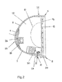
Fig. 2 zeigt einen Außenspiegel mit Blinker im Querschnitt -
Fig. 3 zeigt ein Randstück im Querschnitt -
Fig. 4 zeigt ein Blinkermodul -
Fig. 5 zeigt zwei Beispiele mit Sollbruchstellen -
Fig. 6 zeigt ein weiteres Beispiel mit Sollbruchsstellen -
Fig. 7 : zeigt eine Kameraeinheit - Als beispielhafte Ausführung für die Rückblickeinheit ist ein Außenspiegel gewählt worden. Die erfindungsgemäßen Ausführungsformen lassen sich auch auf eine Rückblickeinheit mit einem Kameramodul erstrecken. Dabei wird die Kamera in ein Kameragehäuse eingebracht und mit einem Gehäusefuß am Fahrzug montiert.
Da eine Kameralösung im Vergleich zum Anbau eines Außenspiegels sehr klein gestaltet werden kann, kann der Airbag auch nur klein dimensioniert sein, da ansonsten nicht genügend Hüllenmaterial im Gehäuse gefaltete werden kann. Allerdings ist auch für den passiven Schutz kein großer Airbag notwednig. -
Fig. 1 ist einen Längsschnitt eines Außenspiegels 1 eines Kraftfahrzeuges mit bewegbaren Teilen des Randbereichs 5 des Spiegelgehäuses 2. Der Außenspiegel 1 hat einen an der Karosserie des Fahrzeuges zu befestigenden Spiegelfuß 3, an dem das in und entgegen Fahrtrichtung 10 schwenkbare Spiegelgehäuse 2 gelagert ist. Zwischen dem Spiegelfuß 3 und dem Spiegelgehäuse 2 ist eine Trennfuge 4 vorgesehen, die den nötigen Freiraum für ein einwandfreies und ungehindertes Schwenken des Spiegelgehäuses 2 ermöglicht. In der Figur ist die Längsachse I des Außenspiegels eingezeichnet. - Das Spiegelgehäuse 2 hat eine Öffnung, die im Wesentlichen durch ein Spiegelglas 16 verschlossen wird. Zwischen dem Spiegelglas 16 und der Innenseite des Randbereiches 5 des Spiegelgehäuses 2 ist ein schmaler umlaufender Spalt 7 vorgesehen, der es ermöglicht, dass das Spiegelglas 16 ungehindert in vertikaler und in horizontaler Richtung verschwenkt werden kann.
- Im Innern des Spiegelgehäuses 2 ist ein Gehäuse 50 mit einem zusammengefalteten Airbag 51 und einer Gasausblasvorrichtung 52 eingebaut. Die Größe, die Form und Anbaurichtung der Airbageinrichtung wird an das jeweilige Spiegeldesign angepasst. Und ist in der Figur nur exemplarisch dargestellt.
- Im oberen, im unteren und im karosseriefernen Teil des Randbereiches 5 sind bewegbare bzw. herauslösbare Teilbereiche 20 im Spiegelgehäuse vorgesehen. Sie werden zum Spiegelgehäuse 2 hin durch eine Trennlinie 21 begrenzt.
Im Falle eines Auslösens des Airbags wird dieser Teil des Randbereiches 5 vollständig vom Spiegelgehäuse 2 gelöst. Der Randbereich 5 kann einstückig aus dem Spiegelgehäuse 2 herausgeformt sein. Es ist auch möglich, den Randbereich 5 durch einen separaten, angesetzten Spiegelrahmen zu bilden. Bei einer solchen Ausführungsform bliebe das Spiegelglas in der Öffnung des Spiegelgehäuses installiert und würde nicht abgesprengt werden, um Verletzungen zu vermeiden. Der Airbag entfaltete sich aus dem Randbereich des Spiegelkopfes und umhüllt Spiegelglas und Spiegelkopf sowohl in als auch entgegen die Fahrtrichtung. Dazu muss der Airbag so positioniert sein, dass der sich entfaltenden Luftsack an einem im Spiegel befindlichen Spiegelträger mit einem Glasverstellmotor und dem Spiegelglas vorbei ausbreiten kann. - Der bewegbare Teil des Randbereiches 5 ist in
Fig. 2 durch eine gestrichelte Trennlinie 21 angedeutet. Längs dieser Trennlinie 21 kann ein Teil 20 des Randbereiches aus dem Spiegelgehäuse 2 herausgelöst werden.
In einer anderen Ausführungsform wird das Spiegelglas 16 aus dem Gehäuse gesprengt. Bei der Verwendung von Plastikglas besteht dabei nur einen geringe Verletzungsgefahr. - Wie
Fig. 2 zeigt, sitzt das Spiegelglas 16 auf einem Spiegelglasträger 15, der mittels eines Verstellantriebes 17 in bekannter Weise verstellt werden kann. Das Spiegelgehäuse 2 hat eine in Fahrtrichtung 10 nach vorn weisende Rückwand 8, die im Querschnitt konkav gekrümmt ist. Das Spiegelgehäuse kann geschlossen sein oder eine Öffnung 9 aufweisen, in die eine Wiederholblinkleuchte 25 eingesetzt werden kann. Sie hat eine Lichtscheibe 26, die mit einem in der Dicke verringerten Rand 28 an der Innenseite der Rückwand 8 befestigt ist. Die Lichtscheibe 26 liegt mit ihrer Außenseite vorteilhaft bündig mit der Außenseite der Rückwand 8. Die Lichtscheibe 26 ist Teil eines Leuchtengehäuses 27, das innerhalb des Innenraumes 18 des Spiegelgehäuses 2 liegt. - Das Spiegelgehäuse 2 ist an seiner Oberseite nahe dem Randbereich 5 mit einer Wasserablaufrinne 22 versehen. In
Fig. 2 ist gegenüberliegend ein Teilbereich 20 des Randbereiches 5 dargestellt, der über eine Sollbruchstelle 31 mit dem restlichen Teil des Spiegelgehäuses 2 verbunden ist. Die Sollbruchstelle 31 verläuft längs der Trennlinie 21 und ist an der Innenseite des Spiegelgehäuses 2 vorgesehen, so dass sie von außen nicht sichtbar ist. Die Sollbruchstelle 31 wird dadurch gebildet, dass der Teilbereich 20 über einen dünnen Steg 24 mit dem Spiegelgehäuse 2 verbunden ist. Im Bereich des Steges 24 ist zwischen dem Teilbereich 20 und dem Spiegelgehäuse 2 ein Spalt 30 vorgesehen. - Die Airbagvorrichtung ist in diesem Ausführungsbeispiel auf der Spiegelträgerplatte15 installiert Ziel ist es bei einer Gefahrensituation das gesamte Spiegelgehäuse vom Rest des Außenspiegels zu trennen. Die Sprengladung des Airbags sprengt das Spiegelgehäuse 2 an der Sollbruchstelle 31 ab, wobei die Wasserablaufrinne 22 als Scharnierlinie dient. Dadurch bleibt das Spiegelgehäuse mit dem Spiegel verbunden und fliegt nicht unkontrolliert herum.
Hier kommen auch Ausführungen zum Einsatz, die flexible Gewebe wie im Stand der Technik verwenden.
In einer weiteren Ausführungsform wird das Spiegelgehäuse auch an der Wasserablaufrinne 22 vollständig vom Rest des Außenspiegels getrennt.
Das vollständige Absprengen des Spiegelgehäuses ist in diesem
Ausführungsbeispiel keine Gefahr, da die Verkabelung, die den Blinker an das elektrische System des Fahrzeugs anschließt, die abgesprengten Bauteile auffängt. - Bei der Ausführungsform nach
Fig. 3 ist der Randbereich 5 mittels einer elastomeren Zwischenschicht 32 an das Spiegelgehäuse 2 angebunden. Entsprechend der vorigen Ausführungsform kann dieser Randbereich 5 als umlaufender Rahmen ausgebildet sein, der über die elastomere Zwischenschicht 32 an das Spiegelgehäuse 2 angebunden ist. Wie bei der vorigen Ausführungsform können auch nur ein oder mehrere Teilbereiche des Randbereiches 5 über diese elastomere Zwischenschicht 32 mit dem Spiegelgehäuse 2 verbunden sein. Die einander zugewandten Ränder 35, 36 des Spiegelgehäuses 2 und des Randbereiches 5 sind jeweils im Querschnitt konvex gekrümmt. Dadurch wird eine zuverlässige Verbindung des Randbereiches 5 über die Zwischenschicht 32 mit dem Spiegelgehäuse 2 erreicht. Die Zwischenschicht 32 hat eine solche Dicke, dass sie im Übergangsbereich zwischen dem Spiegelgehäuse 2 und dem Randbereich 5 einen stetigen Übergang bildet. Dadurch sind sowohl die Innen- als auch die Außenseite des Spiegelgehäuses im Bereich der Zwischenschicht 32 nicht mit einem Absatz versehen, sondern die Innen- und die Außenseite der Zwischenschicht 32 bildet eine stetige Fortsetzung der Innen- bzw. Außenseite des Spiegelgehäuses 2 und des Randbereiches 5. -
Fig. 4 zeigt eine Ausführungsform mit einem Blinker wie inFig. 2 . Das Blinkermodul erstreckt sich von der fahrzeugfernen Seite entlang der Außenkontur der Spiegelgehäuseabdeckung. Das Blinkermodul ist dabei so aufgebaut, dass das Modul über Steckverbindungen oder Klipse mit dem Spiegelgehäuse 2 verbunden ist. Wenn der Airbag ausgelöst wird, wird das Blinkermodul aus dem Spiegelgehäuse gesprengt und der Airbag kann sich durch die entstandene Öffnung ausbreiten. Das abgesprengte Blinkermodul wird über die elektrischen Anschlüsse abgefangen und am freien Herumfliegen gehindert. Die Anbaulinien des Blinkermoduls and das Spiegelgehäuse bilden somit die Sollbruchlinien, die beim Auslösen des Airbags aufgebrochen werden. Durch das Aufbrechen des Spiegelgehäuses entlang des Blinkermoduls entsteht eine ausreichend große Öffnung, um den Luftsack austreten zu lassen. Die Austrittsöffnung erstreckt sich entlang des Speiegelgehäuses mit einer Öffnungsbreite, die der Bauhöhe des Blinkermoduls entspricht. Die Absprengbewegung beginnt am fahrzeugfernen Ende des Außenspiegels, so dass das Blinkermodul in Richtung Fahrzug herausgebrochen wird, Dadurch bleibt auch die Verkabelung, di sich normalerweise am fahrzeugnahen Endes des Blinkermoduls befindet erhalten und kann das Blinkermodul auffangen. -
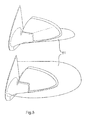
Fig. 5 zeigt ein Beispiel eines Spiegelgehäuses gegen die Fahrtrichtung gesehen.
Die weiße Linie markiert eine Sollbruchstelle, die von außen unsichtbar im Gehäuse verläuft. Das Gehäuse selbst ist in diesem Beispiel auf einem Spiegelrahmen und eine Spiegelfußverkleidung aufgesetzt. Diese Verbindung kann auch abreißbar oder flexibel gestaltet sein. Besonders vorteilhaft ist dabei einen Ausführungsform, die einen sogenannten Skalp als Spiegelgehäuse verwendet. Diese dekorative Abdeckung steht ein austauschbares Aufstecksteil dar, das in das Spiegelgehäuse gesteckt wird. Der Skalp kann mit oder ohne Beleuchtungsmittel gestaltet sein. - Die erfindungsgemäße Lösung für einen Fußgänger Airbag im Außenspiegel muss keinen flächenhafte Entfaltung des Airbags gewährleisten, Vielmehr soll der Außenspiegel mit einer beliebig geformten Luftsack umhüllt sein. Es geht darum beide Seiten der Rückblickvorrichtung, vorwärts und rückwärts mit einem Aufprallschutz zu versehen
- Die Airbagvorrichtung zum Schutz von Fußgängern nach der Erfindung ist so angepasst, dass sie innerhalb des Außenspiegels unter einer Verkleidung befestigt wird. Die Airbagvorrichtung enthält einen Airbag-Satz, der mit Befüllungsgas befüllt werden kann, um die Rückseite des Spiegels und seine Vorderseite zu bedecken, eine Aufblasvorrichtung zum Zuführen von Befüllungsgas in den Airbag und einen Behälter, in dem die Aufblasvorrichtung und der Airbag im zusammengefalteten Zustand untergebracht sind.. Die Aufblasvorrichtung ist so aufgebaut, dass die Austrittsrichtung des Befüllungsgases, das in den Airbag im Inneren des Gehäuses eingespeist wird, sich im Allgemeinen parallel zur Ausrichtung des Spiegels nach außen, erstreckt. Das Gehäuse 50 des Airbags enthält eine Rückwand, die als Öffnungswand dient, die das Hervortreten des Airbags ermöglicht. Bei der Betätigung der oben genannten Airbagvorrichtung füllt sich der Airbag mit Befüllungsgas, das von der Aufblasvorrichtung zugeführt wird, tritt aus dem Gehäuse heraus und entfaltet sich dann, um den Spiegel zu bedecken.
- Die Aufblasvorrichtung ist so aufgebaut, dass ihre Austrittsrichtung von Befüllungsgas zum Airbag im Inneren des Gehäuses im Allgemeinen parallel zur Spiegellängsachse I verläuft.
Folglich lässt im Anfangszustand der Airbagentfaltung das Gehäuse den Airbag entlang der Kontur des Außenspiegels entfalten. - Somit ist die Airbagvorrichtung zum Schutz von Fußgängern im Außenspiegel in der Lage, die Airbags auf stabile Weise und mit einer einfachen Struktur schnell zu entfalten, um den gesamten Außenspiegel zu bedecken.
- Es ist außerdem möglich, dass der Airbag einen Balg-gefalteten Bereich enthält, der in der Richtung von vorne nach hinten in der Art eines Balges gefaltet ist, und dass der Balg-gefaltete Bereich eine solche Länge hat, die ermöglicht, dass sich der nach innen gerollte Bereich bei der Entfaltung des Airbags über Außenspiegel legen kann.
- Zur Auslösung des Airbags gibt es im Stand der Technik beschrieben Methoden. Airbags werden mit Hilfe von Sensorendaten ausgelöst, wobei gängige Sensoren Verzögerungen des Fahrzeugs messen. Eine solche Methode ist für das Auslösen eines Außenairbag eher ungeeignet.
- Für einen Airbag im Außenspiegel bietet es sich an, das Auslösen von einer gemessenen Annäherung abhängig zu machen. Hier werden Ultraschall, Radar oder optische Signale auswerten.
- Das Auslösen erfolgt nicht durch einen Verzögerung des Fahrzeugs sondern durch die Annäherung von der Fahrzeugseite. Damit der Airbag nicht bei jedem vorbeifahrenden Fahrrad ausgelöst wird, muss der Auslösemechanismus intelligent gestaltet sein.
- Hier bieten sich ein Kamerasystem an, das sowohl im Außenspiegel selbst als auch am Fahrzeug befestigt sein kann. Die Kamera detektiert ein sich näherndes Objekt und die verarbeitende Software wertet die Bilder aus. Dabei wird das Objekt nach seine Gefährlichkeit klassifiziert und die Geschwindigkeit der Annäherung bestimmt.
- Eine vorteilhafte Ausführungsform des Auslösungssystems löst den Airbag nur nach einer Objekterkennung einen Fußgängers, Motorrad- oder Fahrradfahrers aus. Ein Seitenaufprall durch ein größeres Objekt löst den Außenspiegel Airbag nicht aus.
- Eine vorteilhafte Ausführung der Auslösesoftware wertet zusätzliche Parameter des Fahrzeugs aus, wie auf dem Fahrzeug -Bussystem zur Verfügung stehen. Das wird im Allgemeinen ein CAN-Bus, ein LIN- Bus oder ein ähnlicher Bus sein. Diese Daten dienen zur Verfeinerung der Auslösesoftware.
- Alle genannten Varianten der Ausführung lassen sich auf eine Rückblickeinheit mit einer Kamera ausweiten. Auch eine solche Rückblickeinheit steht, wie in
Figur 7 dargestellt, über die äußere Kontur des Fahrzeugs hinaus und wird gegebenenfalls zur Gefahr für Fußgänger. Auch hier ist der Schutz durch Auslösung eines Airbags zu begrüßen. Die Sollbruchstelle 21 entlang der Kontur des Gehäuses erlaubt den Austritt des Airbags rund um den Kamerasensor, der in der Mitte dargestellt ist. Die Gestaltung des Airbag ist dabei so, dass die Rückblickeinheit in Fahrtrichtung 10 und gegen die Fahrtrichtung 10 verhüllt ist. - Vorteilhaft ist dabei, dass bei einer Rückblickkamera, die Sensoren nicht getrennt eingebaut oder angeschlossen werden müssen. Bei einem geeigneten Blickwinkel der Kamera oder eines Teilbereichs der Kamera ist einen Auslösung des Airbags direkt nach der Erfassung der Bilddaten möglich.
Claims (12)
- Rückblickeinheit (1) die Befestigungsmittel zur Befestigung an einem Fahrzeug und wenigsten eine Öffnung zur Aufnahme eines reflektierenden Elements (16) oder einer Kamera aufweist wobei die Rückblickeinheit eine Airbagvorrichtung (50. 51, 52) enthält, dadurch gekennzeichnet, dass mindestens eine Sollbruchstelle (21, 31) in der Längsrichtung (I) der Rückblickeinheit (1) verläuft, und die Airbagvorrichtung (50, 51, 52) so gestaltet ist, dass der austretende Airbag (51) die Rückblickeinheit in Fahrt- und gegen die Fahrtrichtung umhüllt.
- Rückblickeinheit nach Anspruch 1 dadurch gekennzeichnet, dass die mindestens eine Sollbruchstelle entlang eines Rahmens (5), der die Öffnung der Rückblickeinheit umfasst, verläuft.
- Rückblickeinheit nach Anspruch 1 dadurch gekennzeichnet, dass die mindestens eine Sollbruchstelle so verläuft, dass das reflektierende Element (16) oder die Kamera aus dem Spiegelgehäuse gesprengt wird.
- Rückblickeinheit nach Anspruch 1 dadurch gekennzeichnet, dass die mindestens eine Sollbruchstelle entlang der Kontur eines Blinkermoduls (25) verläuft, die sich entlang der Längsachse (I) des Gehäuses der Rückblickeinheit erstreckt.
- Rückblickeinheit nach Anspruch 1 dadurch gekennzeichnet, dass die das Blinkermoduls (25) in das Gehäuse der Rückblickeinheit gesteckt ist und sich der Airbag (51) aus der Öffnung entfaltet, die das Blinkermodul vor dem Absprengen einnimmt.
- Rückblickeinheit nach Anspruch 1 dadurch gekennzeichnet, dass die das Blinkermoduls (25) ausgehend vom fahrzeugfernen Ende abgesprengt wird.
- Rückblickeinheit nach Anspruch 1 dadurch gekennzeichnet, dass die mindestens eine Sollbruchstelle aus einer Verringerung der Materialstärke besteht.
- Rückblickeinheit nach Anspruch 1 dadurch gekennzeichnet, dass die mindestens eine Sollbruchstelle aus einem elastischen Material besteht.
- Rückblickeinheit nach Anspruch 1 dadurch gekennzeichnet, dass die Airbagvorrichtung durch ein Steuersignal ausgelöst wird, das über einen Signalisierungsleitung zur Rückblickeinheit gesendet wird.
- Rückblickeinheit nach Anspruch 1 dadurch gekennzeichnet, die Airbagvorrichtung durch ein Steuersignal ausgelöst wird, das durch Sensoren in der Rückblickeinheit erzeugt wird.
- Rückblickeinheit nach Anspruch 7 oder 8 dadurch gekennzeichnet, die Airbagvorrichtung durch ein Steuersignal ausgelöst wird, das nach Bildauswertung mindestens eines Kamerabildes generiert wird.
- Rückblickeinheit nach Anspruch 7 oder 8 dadurch gekennzeichnet, die Airbagvorrichtung durch ein Steuersignal ausgelöst wird, dass durch Auswertung der Annäherung von Objekten generiert wird.
Applications Claiming Priority (1)
| Application Number | Priority Date | Filing Date | Title |
|---|---|---|---|
| DE102009019090A DE102009019090B4 (de) | 2009-04-20 | 2009-04-20 | Rückblickeinheit mit Airbag |
Publications (2)
| Publication Number | Publication Date |
|---|---|
| EP2243665A1 true EP2243665A1 (de) | 2010-10-27 |
| EP2243665B1 EP2243665B1 (de) | 2013-12-25 |
Family
ID=42555935
Family Applications (1)
| Application Number | Title | Priority Date | Filing Date |
|---|---|---|---|
| EP10157487.9A Not-in-force EP2243665B1 (de) | 2009-04-20 | 2010-03-24 | Rückblickeinheit mit Airbag |
Country Status (3)
| Country | Link |
|---|---|
| US (1) | US8002307B2 (de) |
| EP (1) | EP2243665B1 (de) |
| DE (1) | DE102009019090B4 (de) |
Families Citing this family (6)
| Publication number | Priority date | Publication date | Assignee | Title |
|---|---|---|---|---|
| DE102011000740B4 (de) * | 2011-02-15 | 2020-09-03 | Dr. Ing. H.C. F. Porsche Aktiengesellschaft | Außenspiegel für ein Kraftfahrzeug |
| US9067566B1 (en) | 2014-03-10 | 2015-06-30 | Ford Global Technologies, Llc | Active bolster for pedestrian protection |
| DE102014109078B3 (de) * | 2014-06-27 | 2015-10-15 | Laurent Doleac | Zweiradfahrzeug mit Fahrerschutzsystem |
| DE102014217769A1 (de) | 2014-09-05 | 2016-03-10 | Schaeffler Technologies AG & Co. KG | Verstellring für eine Nachstelleinrichtung einer Reibkupplung |
| US10611329B2 (en) * | 2016-05-23 | 2020-04-07 | Panasonic Automotive Systems Company Of America, Division Of Panasonic Corporation Of North America | Shock absorbing speaker |
| CN106515585B (zh) * | 2016-12-09 | 2023-02-07 | 重庆平步青云汽车配件有限公司 | 后视镜防撞测风装置 |
Citations (4)
| Publication number | Priority date | Publication date | Assignee | Title |
|---|---|---|---|---|
| WO1999061288A1 (de) | 1998-05-27 | 1999-12-02 | Inova Gmbh Technische Entwicklungen | Fahrzeugteil mit einer airbagvorrichtung und herstellungsverfahren für ein solches fahrzeugteil |
| US20040182629A1 (en) * | 2003-03-20 | 2004-09-23 | Honda Motor Co., Ltd. | Apparatus for a vehicle for protection of a colliding object |
| DE102008011468A1 (de) | 2007-02-28 | 2008-09-04 | Toyoda Gosei Co., Ltd., Nishikasugai | Airbagvorrichtung zum Schutz von Fußgängern |
| JP2009023600A (ja) | 2007-07-23 | 2009-02-05 | Toyota Motor Corp | 車外用エアバッグ装置 |
Family Cites Families (5)
| Publication number | Priority date | Publication date | Assignee | Title |
|---|---|---|---|---|
| US6172613B1 (en) * | 1998-02-18 | 2001-01-09 | Donnelly Corporation | Rearview mirror assembly incorporating vehicle information display |
| JP3975866B2 (ja) * | 2002-08-30 | 2007-09-12 | 豊田合成株式会社 | 歩行者保護用エアバッグ装置 |
| DE102007033796B4 (de) * | 2007-07-19 | 2011-08-25 | Key Safety Systems, Inc., Mich. | Fahrzeug mit äußerem Aufprallschutz |
| JP5077216B2 (ja) * | 2008-12-12 | 2012-11-21 | 豊田合成株式会社 | エアバッグ装置 |
| JP2010149753A (ja) * | 2008-12-25 | 2010-07-08 | Toyoda Gosei Co Ltd | 歩行者用エアバッグ装置 |
-
2009
- 2009-04-20 DE DE102009019090A patent/DE102009019090B4/de not_active Expired - Fee Related
-
2010
- 2010-03-24 EP EP10157487.9A patent/EP2243665B1/de not_active Not-in-force
- 2010-04-20 US US12/763,275 patent/US8002307B2/en not_active Expired - Fee Related
Patent Citations (4)
| Publication number | Priority date | Publication date | Assignee | Title |
|---|---|---|---|---|
| WO1999061288A1 (de) | 1998-05-27 | 1999-12-02 | Inova Gmbh Technische Entwicklungen | Fahrzeugteil mit einer airbagvorrichtung und herstellungsverfahren für ein solches fahrzeugteil |
| US20040182629A1 (en) * | 2003-03-20 | 2004-09-23 | Honda Motor Co., Ltd. | Apparatus for a vehicle for protection of a colliding object |
| DE102008011468A1 (de) | 2007-02-28 | 2008-09-04 | Toyoda Gosei Co., Ltd., Nishikasugai | Airbagvorrichtung zum Schutz von Fußgängern |
| JP2009023600A (ja) | 2007-07-23 | 2009-02-05 | Toyota Motor Corp | 車外用エアバッグ装置 |
Also Published As
| Publication number | Publication date |
|---|---|
| US8002307B2 (en) | 2011-08-23 |
| EP2243665B1 (de) | 2013-12-25 |
| US20100264633A1 (en) | 2010-10-21 |
| DE102009019090A1 (de) | 2010-11-18 |
| DE102009019090B4 (de) | 2011-03-03 |
Similar Documents
| Publication | Publication Date | Title |
|---|---|---|
| DE102004012478B4 (de) | Vorrichtung für ein Fahrzeug zum Schützen eines kollidierenden Objekts | |
| DE602006001012T2 (de) | Objekterkennung und Fussgänger Schutzsystem | |
| EP2243665B1 (de) | Rückblickeinheit mit Airbag | |
| DE60223241T2 (de) | Gefalteter airbag | |
| EP1732787B2 (de) | Türinnenverkleidung mit einem airbag zum kopf- und/oder schul teraufprallschutz bei einer seitenkollision und/oder einem überschlag und kraftfahrzeugtür mit einer solchen türinnenverkleidung | |
| DE19640434A1 (de) | Einsatztüranordnung | |
| DE3618060A1 (de) | Gaskissen zum schutz der insassen von fahrzeugen | |
| DE102016104151B4 (de) | Aussenairbag | |
| DE10316828A1 (de) | Automobilaußenbord-Airbagsystem | |
| DE102008011468A1 (de) | Airbagvorrichtung zum Schutz von Fußgängern | |
| EP1058633B1 (de) | Gassack-modul | |
| DE102014222949A1 (de) | Flexibler elektroresisitiver Aufprallerkennungssensor für am vorderen 'Träger befestigten Airbag | |
| DE10115064A1 (de) | Sicherheitseinrichtung für die Insassen eines Kraftfahrzeugs | |
| EP1940656B1 (de) | Airbagmodul für ein kraftfahrzeug | |
| DE102011118658A1 (de) | Verfahren und Vorrichtung zur Steuerung eines Schutzsystems in einem Fahrzeug | |
| DE102006015067A1 (de) | Einstückiges Verkleidungs-Band-System für Fahrzeuganwendungen | |
| DE102005027432B4 (de) | Airbag-Vorrichtung zum Schutz von Fußgängern oder dergleichen | |
| DE10261178B3 (de) | Lenkungsanordnung | |
| DE19546242C1 (de) | Schutzeinrichtung für die Insassen eines Kraftfahrzeuges | |
| DE102006042375A1 (de) | Airbagmodul zum Schutz von Personen beim Aufprall auf ein Automobil | |
| DE10114860B4 (de) | Vorrichtung zur Öffnung eines Notausstiegs in Kraftfahrzeugen | |
| DE102022131052A1 (de) | Türmontierter airbag und steuerverfahren zur entfaltung desselben | |
| DE19936353A1 (de) | Airbag-System | |
| DE102018006680B3 (de) | Lenkanordnung für ein Fahrzeug und Fahrzeug mit der Lenkanordnung | |
| DE102011100115A1 (de) | Sicherheitseinrichtung eines Fahrzeugs |
Legal Events
| Date | Code | Title | Description |
|---|---|---|---|
| PUAI | Public reference made under article 153(3) epc to a published international application that has entered the european phase |
Free format text: ORIGINAL CODE: 0009012 |
|
| 17P | Request for examination filed |
Effective date: 20100916 |
|
| AK | Designated contracting states |
Kind code of ref document: A1 Designated state(s): AT BE BG CH CY CZ DE DK EE ES FI FR GB GR HR HU IE IS IT LI LT LU LV MC MK MT NL NO PL PT RO SE SI SK SM TR |
|
| AX | Request for extension of the european patent |
Extension state: AL BA ME RS |
|
| 17Q | First examination report despatched |
Effective date: 20120410 |
|
| REG | Reference to a national code |
Ref country code: DE Ref legal event code: R079 Ref document number: 502010005738 Country of ref document: DE Free format text: PREVIOUS MAIN CLASS: B60R0001060000 Ipc: B60R0021360000 |
|
| RIC1 | Information provided on ipc code assigned before grant |
Ipc: B60R 21/36 20110101AFI20130807BHEP Ipc: B60R 1/06 20060101ALI20130807BHEP Ipc: B60R 1/12 20060101ALI20130807BHEP Ipc: B60R 21/013 20060101ALI20130807BHEP |
|
| GRAP | Despatch of communication of intention to grant a patent |
Free format text: ORIGINAL CODE: EPIDOSNIGR1 |
|
| INTG | Intention to grant announced |
Effective date: 20130913 |
|
| GRAS | Grant fee paid |
Free format text: ORIGINAL CODE: EPIDOSNIGR3 |
|
| GRAA | (expected) grant |
Free format text: ORIGINAL CODE: 0009210 |
|
| AK | Designated contracting states |
Kind code of ref document: B1 Designated state(s): AT BE BG CH CY CZ DE DK EE ES FI FR GB GR HR HU IE IS IT LI LT LU LV MC MK MT NL NO PL PT RO SE SI SK SM TR |
|
| REG | Reference to a national code |
Ref country code: GB Ref legal event code: FG4D Free format text: NOT ENGLISH |
|
| REG | Reference to a national code |
Ref country code: CH Ref legal event code: EP |
|
| REG | Reference to a national code |
Ref country code: AT Ref legal event code: REF Ref document number: 646428 Country of ref document: AT Kind code of ref document: T Effective date: 20140115 |
|
| REG | Reference to a national code |
Ref country code: IE Ref legal event code: FG4D Free format text: LANGUAGE OF EP DOCUMENT: GERMAN |
|
| REG | Reference to a national code |
Ref country code: DE Ref legal event code: R096 Ref document number: 502010005738 Country of ref document: DE Effective date: 20140213 |
|
| PG25 | Lapsed in a contracting state [announced via postgrant information from national office to epo] |
Ref country code: HR Free format text: LAPSE BECAUSE OF FAILURE TO SUBMIT A TRANSLATION OF THE DESCRIPTION OR TO PAY THE FEE WITHIN THE PRESCRIBED TIME-LIMIT Effective date: 20131225 Ref country code: FI Free format text: LAPSE BECAUSE OF FAILURE TO SUBMIT A TRANSLATION OF THE DESCRIPTION OR TO PAY THE FEE WITHIN THE PRESCRIBED TIME-LIMIT Effective date: 20131225 Ref country code: SE Free format text: LAPSE BECAUSE OF FAILURE TO SUBMIT A TRANSLATION OF THE DESCRIPTION OR TO PAY THE FEE WITHIN THE PRESCRIBED TIME-LIMIT Effective date: 20131225 Ref country code: NO Free format text: LAPSE BECAUSE OF FAILURE TO SUBMIT A TRANSLATION OF THE DESCRIPTION OR TO PAY THE FEE WITHIN THE PRESCRIBED TIME-LIMIT Effective date: 20140325 Ref country code: LT Free format text: LAPSE BECAUSE OF FAILURE TO SUBMIT A TRANSLATION OF THE DESCRIPTION OR TO PAY THE FEE WITHIN THE PRESCRIBED TIME-LIMIT Effective date: 20131225 |
|
| REG | Reference to a national code |
Ref country code: NL Ref legal event code: VDEP Effective date: 20131225 |
|
| REG | Reference to a national code |
Ref country code: LT Ref legal event code: MG4D |
|
| PG25 | Lapsed in a contracting state [announced via postgrant information from national office to epo] |
Ref country code: LV Free format text: LAPSE BECAUSE OF FAILURE TO SUBMIT A TRANSLATION OF THE DESCRIPTION OR TO PAY THE FEE WITHIN THE PRESCRIBED TIME-LIMIT Effective date: 20131225 |
|
| PG25 | Lapsed in a contracting state [announced via postgrant information from national office to epo] |
Ref country code: EE Free format text: LAPSE BECAUSE OF FAILURE TO SUBMIT A TRANSLATION OF THE DESCRIPTION OR TO PAY THE FEE WITHIN THE PRESCRIBED TIME-LIMIT Effective date: 20131225 Ref country code: IS Free format text: LAPSE BECAUSE OF FAILURE TO SUBMIT A TRANSLATION OF THE DESCRIPTION OR TO PAY THE FEE WITHIN THE PRESCRIBED TIME-LIMIT Effective date: 20140425 |
|
| PG25 | Lapsed in a contracting state [announced via postgrant information from national office to epo] |
Ref country code: NL Free format text: LAPSE BECAUSE OF FAILURE TO SUBMIT A TRANSLATION OF THE DESCRIPTION OR TO PAY THE FEE WITHIN THE PRESCRIBED TIME-LIMIT Effective date: 20131225 Ref country code: CZ Free format text: LAPSE BECAUSE OF FAILURE TO SUBMIT A TRANSLATION OF THE DESCRIPTION OR TO PAY THE FEE WITHIN THE PRESCRIBED TIME-LIMIT Effective date: 20131225 Ref country code: SK Free format text: LAPSE BECAUSE OF FAILURE TO SUBMIT A TRANSLATION OF THE DESCRIPTION OR TO PAY THE FEE WITHIN THE PRESCRIBED TIME-LIMIT Effective date: 20131225 Ref country code: CY Free format text: LAPSE BECAUSE OF FAILURE TO SUBMIT A TRANSLATION OF THE DESCRIPTION OR TO PAY THE FEE WITHIN THE PRESCRIBED TIME-LIMIT Effective date: 20131225 Ref country code: PT Free format text: LAPSE BECAUSE OF FAILURE TO SUBMIT A TRANSLATION OF THE DESCRIPTION OR TO PAY THE FEE WITHIN THE PRESCRIBED TIME-LIMIT Effective date: 20140428 Ref country code: ES Free format text: LAPSE BECAUSE OF FAILURE TO SUBMIT A TRANSLATION OF THE DESCRIPTION OR TO PAY THE FEE WITHIN THE PRESCRIBED TIME-LIMIT Effective date: 20131225 Ref country code: RO Free format text: LAPSE BECAUSE OF FAILURE TO SUBMIT A TRANSLATION OF THE DESCRIPTION OR TO PAY THE FEE WITHIN THE PRESCRIBED TIME-LIMIT Effective date: 20131225 |
|
| REG | Reference to a national code |
Ref country code: DE Ref legal event code: R097 Ref document number: 502010005738 Country of ref document: DE |
|
| PG25 | Lapsed in a contracting state [announced via postgrant information from national office to epo] |
Ref country code: LU Free format text: LAPSE BECAUSE OF FAILURE TO SUBMIT A TRANSLATION OF THE DESCRIPTION OR TO PAY THE FEE WITHIN THE PRESCRIBED TIME-LIMIT Effective date: 20140324 Ref country code: DK Free format text: LAPSE BECAUSE OF FAILURE TO SUBMIT A TRANSLATION OF THE DESCRIPTION OR TO PAY THE FEE WITHIN THE PRESCRIBED TIME-LIMIT Effective date: 20131225 |
|
| PLBE | No opposition filed within time limit |
Free format text: ORIGINAL CODE: 0009261 |
|
| REG | Reference to a national code |
Ref country code: CH Ref legal event code: PL |
|
| STAA | Information on the status of an ep patent application or granted ep patent |
Free format text: STATUS: NO OPPOSITION FILED WITHIN TIME LIMIT |
|
| PG25 | Lapsed in a contracting state [announced via postgrant information from national office to epo] |
Ref country code: PL Free format text: LAPSE BECAUSE OF FAILURE TO SUBMIT A TRANSLATION OF THE DESCRIPTION OR TO PAY THE FEE WITHIN THE PRESCRIBED TIME-LIMIT Effective date: 20131225 |
|
| 26N | No opposition filed |
Effective date: 20140926 |
|
| REG | Reference to a national code |
Ref country code: IE Ref legal event code: MM4A |
|
| REG | Reference to a national code |
Ref country code: DE Ref legal event code: R097 Ref document number: 502010005738 Country of ref document: DE Effective date: 20140926 |
|
| PG25 | Lapsed in a contracting state [announced via postgrant information from national office to epo] |
Ref country code: CH Free format text: LAPSE BECAUSE OF NON-PAYMENT OF DUE FEES Effective date: 20140331 Ref country code: LI Free format text: LAPSE BECAUSE OF NON-PAYMENT OF DUE FEES Effective date: 20140331 Ref country code: IE Free format text: LAPSE BECAUSE OF NON-PAYMENT OF DUE FEES Effective date: 20140324 |
|
| PG25 | Lapsed in a contracting state [announced via postgrant information from national office to epo] |
Ref country code: SI Free format text: LAPSE BECAUSE OF FAILURE TO SUBMIT A TRANSLATION OF THE DESCRIPTION OR TO PAY THE FEE WITHIN THE PRESCRIBED TIME-LIMIT Effective date: 20131225 |
|
| PG25 | Lapsed in a contracting state [announced via postgrant information from national office to epo] |
Ref country code: MT Free format text: LAPSE BECAUSE OF FAILURE TO SUBMIT A TRANSLATION OF THE DESCRIPTION OR TO PAY THE FEE WITHIN THE PRESCRIBED TIME-LIMIT Effective date: 20131225 |
|
| REG | Reference to a national code |
Ref country code: FR Ref legal event code: PLFP Year of fee payment: 7 |
|
| PG25 | Lapsed in a contracting state [announced via postgrant information from national office to epo] |
Ref country code: SM Free format text: LAPSE BECAUSE OF FAILURE TO SUBMIT A TRANSLATION OF THE DESCRIPTION OR TO PAY THE FEE WITHIN THE PRESCRIBED TIME-LIMIT Effective date: 20131225 |
|
| REG | Reference to a national code |
Ref country code: AT Ref legal event code: MM01 Ref document number: 646428 Country of ref document: AT Kind code of ref document: T Effective date: 20150324 |
|
| PG25 | Lapsed in a contracting state [announced via postgrant information from national office to epo] |
Ref country code: MC Free format text: LAPSE BECAUSE OF FAILURE TO SUBMIT A TRANSLATION OF THE DESCRIPTION OR TO PAY THE FEE WITHIN THE PRESCRIBED TIME-LIMIT Effective date: 20131225 |
|
| PG25 | Lapsed in a contracting state [announced via postgrant information from national office to epo] |
Ref country code: GR Free format text: LAPSE BECAUSE OF FAILURE TO SUBMIT A TRANSLATION OF THE DESCRIPTION OR TO PAY THE FEE WITHIN THE PRESCRIBED TIME-LIMIT Effective date: 20140326 Ref country code: BG Free format text: LAPSE BECAUSE OF FAILURE TO SUBMIT A TRANSLATION OF THE DESCRIPTION OR TO PAY THE FEE WITHIN THE PRESCRIBED TIME-LIMIT Effective date: 20131225 Ref country code: IT Free format text: LAPSE BECAUSE OF FAILURE TO SUBMIT A TRANSLATION OF THE DESCRIPTION OR TO PAY THE FEE WITHIN THE PRESCRIBED TIME-LIMIT Effective date: 20131225 |
|
| PG25 | Lapsed in a contracting state [announced via postgrant information from national office to epo] |
Ref country code: TR Free format text: LAPSE BECAUSE OF FAILURE TO SUBMIT A TRANSLATION OF THE DESCRIPTION OR TO PAY THE FEE WITHIN THE PRESCRIBED TIME-LIMIT Effective date: 20131225 Ref country code: HU Free format text: LAPSE BECAUSE OF FAILURE TO SUBMIT A TRANSLATION OF THE DESCRIPTION OR TO PAY THE FEE WITHIN THE PRESCRIBED TIME-LIMIT; INVALID AB INITIO Effective date: 20100324 Ref country code: BE Free format text: LAPSE BECAUSE OF FAILURE TO SUBMIT A TRANSLATION OF THE DESCRIPTION OR TO PAY THE FEE WITHIN THE PRESCRIBED TIME-LIMIT Effective date: 20140331 |
|
| PG25 | Lapsed in a contracting state [announced via postgrant information from national office to epo] |
Ref country code: AT Free format text: LAPSE BECAUSE OF NON-PAYMENT OF DUE FEES Effective date: 20150324 |
|
| REG | Reference to a national code |
Ref country code: FR Ref legal event code: PLFP Year of fee payment: 8 |
|
| REG | Reference to a national code |
Ref country code: FR Ref legal event code: PLFP Year of fee payment: 9 |
|
| PG25 | Lapsed in a contracting state [announced via postgrant information from national office to epo] |
Ref country code: MK Free format text: LAPSE BECAUSE OF FAILURE TO SUBMIT A TRANSLATION OF THE DESCRIPTION OR TO PAY THE FEE WITHIN THE PRESCRIBED TIME-LIMIT Effective date: 20131225 |
|
| PGFP | Annual fee paid to national office [announced via postgrant information from national office to epo] |
Ref country code: GB Payment date: 20200323 Year of fee payment: 11 |
|
| REG | Reference to a national code |
Ref country code: DE Ref legal event code: R084 Ref document number: 502010005738 Country of ref document: DE |
|
| PGFP | Annual fee paid to national office [announced via postgrant information from national office to epo] |
Ref country code: FR Payment date: 20210323 Year of fee payment: 12 |
|
| PGFP | Annual fee paid to national office [announced via postgrant information from national office to epo] |
Ref country code: DE Payment date: 20210319 Year of fee payment: 12 |
|
| GBPC | Gb: european patent ceased through non-payment of renewal fee |
Effective date: 20210324 |
|
| PG25 | Lapsed in a contracting state [announced via postgrant information from national office to epo] |
Ref country code: GB Free format text: LAPSE BECAUSE OF NON-PAYMENT OF DUE FEES Effective date: 20210324 |
|
| REG | Reference to a national code |
Ref country code: DE Ref legal event code: R119 Ref document number: 502010005738 Country of ref document: DE |
|
| PG25 | Lapsed in a contracting state [announced via postgrant information from national office to epo] |
Ref country code: FR Free format text: LAPSE BECAUSE OF NON-PAYMENT OF DUE FEES Effective date: 20220331 Ref country code: DE Free format text: LAPSE BECAUSE OF NON-PAYMENT OF DUE FEES Effective date: 20221001 |