EP2242960B1 - Saugleitung für kondensatpumpe - Google Patents
Saugleitung für kondensatpumpe Download PDFInfo
- Publication number
- EP2242960B1 EP2242960B1 EP09703989.5A EP09703989A EP2242960B1 EP 2242960 B1 EP2242960 B1 EP 2242960B1 EP 09703989 A EP09703989 A EP 09703989A EP 2242960 B1 EP2242960 B1 EP 2242960B1
- Authority
- EP
- European Patent Office
- Prior art keywords
- conduit
- membrane
- tubular member
- water
- rim
- Prior art date
- Legal status (The legal status is an assumption and is not a legal conclusion. Google has not performed a legal analysis and makes no representation as to the accuracy of the status listed.)
- Not-in-force
Links
- XLYOFNOQVPJJNP-UHFFFAOYSA-N water Substances O XLYOFNOQVPJJNP-UHFFFAOYSA-N 0.000 claims description 54
- 239000012528 membrane Substances 0.000 claims description 32
- 238000010438 heat treatment Methods 0.000 claims description 18
- 230000003584 silencer Effects 0.000 description 26
- 230000005499 meniscus Effects 0.000 description 13
- 238000004378 air conditioning Methods 0.000 description 10
- 230000037452 priming Effects 0.000 description 3
- 230000003247 decreasing effect Effects 0.000 description 2
- 238000000034 method Methods 0.000 description 2
- 239000000203 mixture Substances 0.000 description 2
- 239000000523 sample Substances 0.000 description 2
- 238000009833 condensation Methods 0.000 description 1
- 230000005494 condensation Effects 0.000 description 1
- 238000001816 cooling Methods 0.000 description 1
- 230000007423 decrease Effects 0.000 description 1
- 230000001419 dependent effect Effects 0.000 description 1
- 238000001514 detection method Methods 0.000 description 1
- 230000035622 drinking Effects 0.000 description 1
- 230000000694 effects Effects 0.000 description 1
- 230000005484 gravity Effects 0.000 description 1
- 238000009434 installation Methods 0.000 description 1
- 230000007794 irritation Effects 0.000 description 1
- 239000007788 liquid Substances 0.000 description 1
- 230000002093 peripheral effect Effects 0.000 description 1
- 238000005086 pumping Methods 0.000 description 1
- 238000003756 stirring Methods 0.000 description 1
- 239000010902 straw Substances 0.000 description 1
- 239000002351 wastewater Substances 0.000 description 1
Images

Classifications
-
- F—MECHANICAL ENGINEERING; LIGHTING; HEATING; WEAPONS; BLASTING
- F24—HEATING; RANGES; VENTILATING
- F24F—AIR-CONDITIONING; AIR-HUMIDIFICATION; VENTILATION; USE OF AIR CURRENTS FOR SCREENING
- F24F13/00—Details common to, or for air-conditioning, air-humidification, ventilation or use of air currents for screening
- F24F13/22—Means for preventing condensation or evacuating condensate
- F24F13/222—Means for preventing condensation or evacuating condensate for evacuating condensate
-
- F—MECHANICAL ENGINEERING; LIGHTING; HEATING; WEAPONS; BLASTING
- F24—HEATING; RANGES; VENTILATING
- F24F—AIR-CONDITIONING; AIR-HUMIDIFICATION; VENTILATION; USE OF AIR CURRENTS FOR SCREENING
- F24F11/00—Control or safety arrangements
- F24F11/30—Control or safety arrangements for purposes related to the operation of the system, e.g. for safety or monitoring
-
- F—MECHANICAL ENGINEERING; LIGHTING; HEATING; WEAPONS; BLASTING
- F24—HEATING; RANGES; VENTILATING
- F24F—AIR-CONDITIONING; AIR-HUMIDIFICATION; VENTILATION; USE OF AIR CURRENTS FOR SCREENING
- F24F13/00—Details common to, or for air-conditioning, air-humidification, ventilation or use of air currents for screening
- F24F13/22—Means for preventing condensation or evacuating condensate
- F24F13/222—Means for preventing condensation or evacuating condensate for evacuating condensate
- F24F2013/227—Condensate pipe for drainage of condensate from the evaporator
-
- F—MECHANICAL ENGINEERING; LIGHTING; HEATING; WEAPONS; BLASTING
- F24—HEATING; RANGES; VENTILATING
- F24F—AIR-CONDITIONING; AIR-HUMIDIFICATION; VENTILATION; USE OF AIR CURRENTS FOR SCREENING
- F24F2110/00—Control inputs relating to air properties
-
- F—MECHANICAL ENGINEERING; LIGHTING; HEATING; WEAPONS; BLASTING
- F24—HEATING; RANGES; VENTILATING
- F24F—AIR-CONDITIONING; AIR-HUMIDIFICATION; VENTILATION; USE OF AIR CURRENTS FOR SCREENING
- F24F2140/00—Control inputs relating to system states
- F24F2140/30—Condensation of water from cooled air
Definitions
- the present invention relates to conduits for use with condensate removal pumps which are employed to remove waste water from air conditioning systems.
- Air conditioning systems take in warm air and expel cooler air in order to provide a more comfortable living or working environment. The process of chilling the air causes condensation to form on the heat exchanger, producing a steady stream of water dripping down into a collection tray and then to a drain.
- the amount of water produced depends on the humidity level in the environment and other factors, but 10 litres every hour is quite common.
- a self priming condensate removal pump is typically employed to convey the water through a discharge tube to the outside of a building.
- Such pumps are preferably demand driven so that they only operate when there is water waiting to be discharged from the system.
- differential temperature sensors are preferred to water level sensors since water level sensors can be difficult and time consuming to install, particularly when there is limited space is available.
- differential temperature sensors are less accurate than water level sensors and can leave the pump running for long periods of time, even when there is no water to pump. This is wasteful of energy, causes wear to the pump and creates unwanted noise.
- a further problem associated with known condensate removal pumps is the noise created when the water has nearly run out.
- a hose conveys the water from the drainage pipe of the air conditioning unit to the inlet of the pump.
- a mixture of water and air is drawn up the tube causing a gurgling sound, similar to that made by a drinking straw, to be produced.
- This noise causes irritation and complaints from users.
- differential temperature sensing is used to control the pump as the pump is left running for long periods of time.
- a conduit for a condensate removal pump comprising a tubular member having a rim at a distal end thereof, wherein the rim is perpendicular to the axis of the tubular member.
- EP 1 318 361 A1 discloses a pump assembly comprising a pump and a pump reservoir.
- a tubular pump inlet is arranged so that it depends into the pump reservoir, the distal rim of the pump inlet is perpendicular to the axis of the pump inlet.
- EP 0 552 913 A1 discloses a pump for periodically removing condensate from a sump in an air conditioner.
- the inlet to the pump is in the form of a pipe having a distal rim which is perpendicular to the axis of the pipe.
- the present invention provides, in accordance with claim 1, a conduit for a condensate removal pump comprising a tubular member having a rim at a distal end thereof, characterised in that the rim is profiled such that only a portion of the rim lies in a plane which is located at the extreme distal end of the tubular member and which is perpendicular to the axis of the tubular member, the conduit further comprising a resilient membrane which extends across the interior of the tubular member; the membrane having at least one slit which is arranged to open to allow water to pass through the membrane when water is drawn through the conduit by a condensate removal pump.
- a conduit for a condensate removal pump comprising a tubular member having a rim at a distal end thereof, characterised in that the rim is profiled such that only a portion of the rim lies in a plane which is located at the extreme distal end of the tubular member and which is perpendicular to the axis of the tubular member, the conduit
- the conduit of the present invention helps to minimise noise nuisance from gurgling as the membrane helps to minimise noise escaping from within the tubular member and the profiled rim helps to prevent a mixture of water and air being draw into the tubular member.
- the water level surrounding the tubular member decreases.
- the surface of the water forms a meniscus on the outer surface of the tubular member due to surface tension.
- the meniscus clings onto the rim until the water level has decreased to such an extent that the surface tension is no longer able to maintain the meniscus in contact with the rim. At this point the meniscus breaks suddenly.
- the rim may have any desired configuration. For example, an oblique taper or curved configuration. However the rim preferably has a castellated configuration which helps to ensure that the meniscus breaks at the lowest possible water level.
- the membrane comprises a single slit to minimise the number of noise paths through the membrane.
- the membrane is located proximate the distal end of the tubular member to maximise the noise shielding effect.
- the membrane is supported by a support member and moveable with respect to the tubular member.
- a resilient member is provided for controlling movement of the membrane. This arrangement provides a safeguard in the event that the slit becomes blocked by allowing the membrane to move and provide a bypass for the water.
- the present invention provides a combination of a conduit according to the first aspect of the present invention and a combined sensor and suction tube assembly.
- the combined sensor and suction tube assembly comprising: a tube having a proximal end which is arranged to be connected to the inlet of a condensate removal pump and a distal end which is arranged so that water may be drawn through the tube, a self heating thermistor coupled to the tube, and a relay means which is arranged to relay an operational parameter of the self heating thermistor indicative of the presence of water to the condensate removal pump, wherein the combined sensor and suction tube assembly is sized to fit within a pipe having an inner diameter of no more than 20mm, wherein the conduit is arranged to be connected to the distal end of the combined sensor and suction tube assembly.
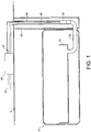
- Figure 1 shows a wall mounted air conditioning unit 10 which comprises a condensate tray 20 into which condensed water drips from the cooling fins (not shown).
- a 14mm internal diameter drainage pipe 30 extends from the condensate tray 20, through plastic trunking 40 into a cavity above the ceiling 5.
- a self priming condensate removal pump 60 is located in the ceiling cavity for pumping the condensed water to an outside drain through discharge tube 61.
- a combined sensor, suction tube and silencer assembly 50 is located within the drainage pipe 30.
- a hose 65 connects a proximal end 49 of the suction tube 55 (see Figure 2 ) to the inlet of the pump 60 and a cable 69 connects self heating thermistors 56, 57 (see Figure 2 ) to control circuitry of the pump 60 via connector 67.
- the combined sensor, suction tube and silencer assembly 50 comprises a suction tube 55 located within a housing 59.
- First and second self heating thermistors 56, 57 are supported within the housing 59 by the cable 69 which is secured to the outer surface of the suction tube 55 by a clip (not shown).
- the first self heating thermistor 56 is located proximate the distal end 48 of the suction tube 55 and the second self heating thermistor is located approximately half way along the length of the suction tube 55.
- Both self heating thermistors 56, 57 are provided with a small electrical current of approximately 20mA each via cable 69. When there is no water present the self heating thermistors are hot and their electrical resistance is high. Conversely, when there is water present, the self heating thermistors are cooled by the water and their electrical resistance falls. The electrical resistance of the self heating thermistors is an operational parameter which may be relayed to the pump control circuitry via the cable 69 to indicate the presence or absence of water in the pipe 30.
- the combined sensor, suction tube and silencer assembly 50 further comprises a silencer conduit 51 which comprises a tubular member 47 connected to the distal end 48 of the suction tube 55.
- a gap 58 is located between the housing 59 and the silencer conduit 51 to allow water to access the first and second self heating thermistors 56, 57.
- the silencer conduit 51 has a profiled rim 53, 54 which has a castellated configuration such that lower portions of the rim 53 are located at the extreme distal end of the silencer conduit 51 in a plane which is perpendicular to the axis of the tubular member 47, and upper portions of the rim 54 are located in a plane perpendicular to the axis of the tubular member 47 but located further towards the proximal end of the suction tube 55.
- Figure 3 shows an alternative view of the rim 53, 54 at 90° to the view shown in Figure 2 .
- a resilient membrane 52 extends across the interior of the tubular member 47 to help prevent noise from within the suction tube 55 and hose 65 escaping.
- the resilient membrane 52 has a slit (not shown) which is arranged to open to allow water to pass through the membrane when water is sucked through the suction tube 55 by the pump 60.
- a slit (not shown) which is arranged to open to allow water to pass through the membrane when water is sucked through the suction tube 55 by the pump 60.
- the slit remains substantially closed thereby helping to prevent noise from within the suction tube 55 and hose 65 escaping.
- suction tube and silencer assembly 50 is suspended within the drainage pipe 30 of the air conditioning unit 10. Condensed water is collected by the condensate tray 20 and flows into the drainage pipe 30 where it encounters the lower end of the combined sensor, suction tube and silencer assembly 50. Initially the pump 60 does not operate so that the water level in the drainage pipe 30 continues to rise until it encounters the first self heating thermistor 56. At this point the electrical resistance of the self heating thermistor 56 falls and the pump is switched on.
- the second self heating thermistor 57 provides an emergency water level sensing facility as a fail safe.
- the pump 60 When the pump 60 is operating the level of the water falls until it reaches the profiled rim 53, 54.
- the surface of the water forms a meniscus on the outer surface of the tubular member 47 due to surface tension.
- the meniscus As the water level moves past the rim 53, 54 the meniscus clings onto the rim 53, until the water level has decreased to such an extent that the surface tension is no longer sufficient to maintain the meniscus in contact with the rim 53, 54. At this point the meniscus breaks suddenly.
- Figure 4 shows an alternative configuration for the profiled rim of the silencer conduit 51.
- the lower portion of the rim 54' has a curved shape.
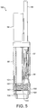
- Figure 5 shows a second embodiment of a combined sensor, suction tube and silencer assembly 150 according to the present invention. Where possible like reference numerals have been used to indicate like features.
- the combined sensor, suction tube and silencer assembly 150 comprises a suction tube 55 located within a housing 59.
- First and second self heating thermistors 56, 57 are supported within the housing 59 by a cable 69.
- the combined sensor, suction tube and silencer assembly 150 further comprises a silencer conduit 151 which comprises a tubular member 147 connected to the suction tube 55.
- the rim of the silencer conduit 151 may be as described above with reference to any one of Figures 2, 3 or 4 .
- a support ring 155 is fixed within the tubular member 147 and a resilient membrane 152 is supported on the support ring 155.
- the resilient membrane 152 extends across the interior of the tubular member 147 and has a slit which is arranged to open to allow water to pass through the membrane when water is sucked through the suction tube 55.
- the support ring 155 bears against a shoulder 156 formed in the silencer conduit 151.
- a helical spring 160 is located within the tubular member 147. The helical spring bears against the upper surface of the resilient membrane 152 at its lowermost end and against a rim 157 formed in the silencer conduit 151 at its uppermost end.
- the strength of the helical spring 160 is such that it holds the resilient membrane 152 in place against the support ring 155 during normal operation of the combined sensor, suction tube and silencer assembly 150. That is to say when there is no blockage of the slit in the resilient membrane 152. However, should the slit in the resilient membrane 152 become blocked, the helical spring 160 will compress to allow the resilient membrane 152 to move upwardly within the tubular member 147 to allow water to pass into the suction tube 55. This provides an additional safeguard in the event that the resilient membrane 152 becomes blocked by debris.
- the resilient membrane 152 may be fixedly attached to the support ring 155 and the support ring 155 may be moveable with respect to the tubular member 147.
- the support ring 155 may be arranged to pivot within the tubular member 147 about a sprung hinge.
- the sprung hinge is arranged to hold the support ring in place during normal operation, and to allow the support ring to move, to allow water to flow into the suction tube 55, in the event that the slit in the resilient membrane becomes blocked.
- the combined sensor, suction tube and silencer assembly 50 it is not necessary for the combined sensor, suction tube and silencer assembly 50 to be located within the drainage pipe 30 of the air conditioning unit 10. If desired the combined sensor, suction tube and silencer assembly 50 could be suspended directly into the condensate tray 20 or other reservoir of liquid to be removed.
- the pump may be a gravity fed pump, appropriately positioned, rather than a self priming pump.
- the silencer conduit 51 could be an integral part of the suction tube 55.
- the assembly 50 could be without a silencer conduit 51.
- the silencer conduit 51 could be used in combination with a known sensor assembly such as a differential temperature sensor, float switch or conductivity probe.
Landscapes
- Engineering & Computer Science (AREA)
- Chemical & Material Sciences (AREA)
- Combustion & Propulsion (AREA)
- Mechanical Engineering (AREA)
- General Engineering & Computer Science (AREA)
- Reciprocating Pumps (AREA)
- Devices For Blowing Cold Air, Devices For Blowing Warm Air, And Means For Preventing Water Condensation In Air Conditioning Units (AREA)
- Endoscopes (AREA)
- Structures Of Non-Positive Displacement Pumps (AREA)
- Air Conditioning Control Device (AREA)
Claims (6)
- Leitung (51) für eine Kondensatbeseitigungspumpe (60), welche aufweist:ein rohrförmiges Element (47), das an seinem distalen Ende eine Krempe (53, 54) aufweist, dadurch gekennzeichnet, dass die Krempe (53, 54) derart profiliert ist, dass nur ein Abschnitt der Krempe (53) in einer Ebene liegt, die am äußersten distalen Ende des rohrförmigen Elements (47) angeordnet ist und die senkrecht zur Achse des rohrförmigen Elements (47) ist,wobei die Leitung (51) ferner eine elastische Membrane (52) aufweist, die sich über den Innenraum des rohrförmigen Elements (47) erstreckt, wobei die Membrane (52) zumindest einen Schlitz aufweist, der zum Öffnen angeordnet ist, um zu erlauben, dass Wasser durch die Membrane (52) hindurchtritt, wenn von einer Kondensatbeseitigungspumpe (60) Wasser durch die Leitung (51) gesaugt wird.
- Leitung (51) nach Anspruch 1, wobei die Krempe (53, 54) eine durchbrochene Konfiguration aufweist.
- Leitung (51) nach Anspruch 1 oder 2, wobei die Membrane (52) einen einzelnen Schlitz aufweist.
- Leitung (51) nach einem der Ansprüche 1 bis 3, wobei die Membrane (52) nächst dem distalen Ende des rohrförmigen Elements (47) angeordnet ist.
- Leitung (51) nach einem der Ansprüche 1 bis 4, wobei die Membrane (52) von einem Trägerelement (155) getragen ist, und wobei die Membrane (52) in Bezug auf das rohrförmige Element (47) bewegbar ist, wobei die Leitung (51) ferner ein elastisches Element (160) aufweist, um eine Bewegung der Membrane (52) zu steuern.
- Kombination einer Leitung (51) nach einem der Ansprüche 1 bis 5 und einer kombinierten Sensor- und Saugrohranordnung (50), wobei die kombinierte Sensor- und Saugrohranordnung (50) aufweist:- ein Rohr (55) mit einem proximalen Ende (49), das zur Verbindung mit dem Einlass einer Kondensatbeseitigungspumpe (60) angeordnet ist, und einem distalen Ende (48), das so angeordnet ist, dass Wasser durch das Rohr (55) gesaugt werden kann,- einen selbstheizenden Thermistor (56), der mit dem Rohr (55) verbunden ist, und- ein Übertragungsmittel (69), das angeordnet ist, um einen Betriebsparameter des selbstheizenden Thermistors (56), der das Vorhandensein von Wasser angibt, zur Kondensatbeseitigungspumpe (60) zu übertragen,- wobei die kombinierte Sensor- und Saugrohranordnung (50) so bemessen ist, dass sie in ein Rohr (30) mit einem Innendurchmesser von nicht mehr als 20mm passt,wobei die Leitung (51) angeordnet ist, um mit dem distalen Ende (48) der kombinierten Sensor- und Saugrohranordnung (50) verbunden zu werden.
Applications Claiming Priority (2)
| Application Number | Priority Date | Filing Date | Title |
|---|---|---|---|
| GBGB0801063.9A GB0801063D0 (en) | 2008-01-21 | 2008-01-21 | Conduit for a condensate removal pump |
| PCT/GB2009/000147 WO2009093010A1 (en) | 2008-01-21 | 2009-01-20 | Conduit for a condensate removal pump |
Publications (2)
| Publication Number | Publication Date |
|---|---|
| EP2242960A1 EP2242960A1 (de) | 2010-10-27 |
| EP2242960B1 true EP2242960B1 (de) | 2017-08-23 |
Family
ID=39166096
Family Applications (1)
| Application Number | Title | Priority Date | Filing Date |
|---|---|---|---|
| EP09703989.5A Not-in-force EP2242960B1 (de) | 2008-01-21 | 2009-01-20 | Saugleitung für kondensatpumpe |
Country Status (7)
| Country | Link |
|---|---|
| US (1) | US8798449B2 (de) |
| EP (1) | EP2242960B1 (de) |
| JP (1) | JP5305362B2 (de) |
| BR (1) | BRPI0907037A2 (de) |
| GB (1) | GB0801063D0 (de) |
| RU (1) | RU2488045C2 (de) |
| WO (1) | WO2009093010A1 (de) |
Families Citing this family (14)
| Publication number | Priority date | Publication date | Assignee | Title |
|---|---|---|---|---|
| US9713211B2 (en) * | 2009-09-24 | 2017-07-18 | Cree, Inc. | Solid state lighting apparatus with controllable bypass circuits and methods of operation thereof |
| US10264637B2 (en) | 2009-09-24 | 2019-04-16 | Cree, Inc. | Solid state lighting apparatus with compensation bypass circuits and methods of operation thereof |
| US8602579B2 (en) * | 2009-09-25 | 2013-12-10 | Cree, Inc. | Lighting devices including thermally conductive housings and related structures |
| US8777449B2 (en) * | 2009-09-25 | 2014-07-15 | Cree, Inc. | Lighting devices comprising solid state light emitters |
| US9285103B2 (en) * | 2009-09-25 | 2016-03-15 | Cree, Inc. | Light engines for lighting devices |
| GB201109240D0 (en) | 2011-06-01 | 2011-07-13 | Charles Austen Pumps Ltd | Condensate collection device |
| US9839083B2 (en) | 2011-06-03 | 2017-12-05 | Cree, Inc. | Solid state lighting apparatus and circuits including LED segments configured for targeted spectral power distribution and methods of operating the same |
| US9631833B2 (en) | 2011-06-17 | 2017-04-25 | Emerson Electric Co. | Climate control systems, and methods relating thereto |
| US8572991B2 (en) | 2011-06-17 | 2013-11-05 | Emerson Electric Co. | Condensate liquid level sensor and drain fitting |
| FR2982354B1 (fr) * | 2011-11-08 | 2013-12-20 | Sauermann Ind Sa | Dispositif de relevage de condensats, mettant en oeuvre un metal bactericide. |
| JP6322802B2 (ja) * | 2013-03-13 | 2018-05-16 | パナソニックIpマネジメント株式会社 | 洗浄機能付きレンジフード |
| US10788241B2 (en) * | 2017-10-26 | 2020-09-29 | Rheem Manufacturing Company | Air conditioner with condensation drain assembly and improved filter rack |
| GB2597667B (en) * | 2020-07-27 | 2022-11-02 | Aspen Pumps Ltd | Condensate pump arrangement |
| CN114135999B (zh) * | 2021-11-29 | 2023-01-13 | 浙江富士精工科技有限公司 | 空调用智能排水泵及其制造方法 |
Family Cites Families (29)
| Publication number | Priority date | Publication date | Assignee | Title |
|---|---|---|---|---|
| US996588A (en) | 1909-09-02 | 1911-06-27 | Nat Carbonated Liquid Co | Combined union and check valve. |
| US3227872A (en) * | 1959-05-25 | 1966-01-04 | Robert C Nemeth | Mass spectrometer leak detecting device in combination with a gettering chamber |
| US3905203A (en) * | 1973-06-15 | 1975-09-16 | Carlyle W Jacob | Refrigeration and water condensate removal apparatus |
| US4383415A (en) * | 1979-12-04 | 1983-05-17 | Jacob Carlyle W | Refrigeration and water condensate removal apparatus |
| US4392782A (en) * | 1980-11-13 | 1983-07-12 | Comact Pump Corporation | Liquid level controller |
| US4507056A (en) * | 1981-09-11 | 1985-03-26 | Logic Devices, Inc. | Liquid circulation apparatus and method |
| JPH0545829Y2 (de) * | 1988-01-06 | 1993-11-26 | ||
| US5182925A (en) * | 1991-05-13 | 1993-02-02 | Mile High Equipment Company | Integrally formed, modular ice cuber having a stainless steel evaporator and microcontroller |
| JP2508238Y2 (ja) * | 1991-10-01 | 1996-08-21 | 三機工業株式会社 | 冷房機における吸引式ドレン強制排出装置 |
| GB9201466D0 (en) | 1992-01-23 | 1992-03-11 | Imi Air Conditioning Ltd | Improvements relating to air conditioners |
| JPH06221596A (ja) * | 1993-01-26 | 1994-08-09 | Mitsubishi Electric Corp | 空気調和機のドレンポンプ制御装置 |
| US5301516A (en) * | 1993-02-11 | 1994-04-12 | Forrest Poindexter | Potable water collection apparatus |
| JPH07280417A (ja) | 1994-04-13 | 1995-10-27 | Mitsubishi Heavy Ind Ltd | コンテナ用冷凍ユニットのドレンホース |
| DE19653879A1 (de) * | 1996-12-21 | 1998-06-25 | Mannesmann Vdo Ag | Füllstandsgrenzgeber und Verfahren zur Ermittlung eines Unter- oder Überschreitens einer vorgesehenen Füllhöhe von Flüssigkeit in einem Behälter |
| US5882416A (en) * | 1997-06-19 | 1999-03-16 | Advanced Technology Materials, Inc. | Liquid delivery system, heater apparatus for liquid delivery system, and vaporizer |
| DE29909689U1 (de) | 1999-06-02 | 1999-08-12 | Liebherr-Hausgeräte GmbH, 88416 Ochsenhausen | Entwässerungsventil |
| JP2001159556A (ja) | 1999-12-03 | 2001-06-12 | Matsushita Refrig Co Ltd | 空気調和機の水位検知装置 |
| JP2002162285A (ja) | 2000-10-31 | 2002-06-07 | Applied Materials Inc | 液体収容装置および液面検知方法 |
| JP2003097450A (ja) * | 2001-09-27 | 2003-04-03 | Daikin Ind Ltd | ベローズポンプ、ドレンポンプユニットおよび空気調和機 |
| ES2252399T3 (es) * | 2001-12-04 | 2006-05-16 | Aspen Pumps Limited | Mejoras en o relacionadas con bombas. |
| CH695513A5 (fr) * | 2002-02-06 | 2006-06-15 | Gotec S A | Pompe monobloc pour l'évacuation de liquide de condensation. |
| DE10241237A1 (de) * | 2002-09-06 | 2004-03-25 | Friess GmbH Kälte-Klima-Umwelttechnik Werksvertretungen | Vorrichtung zum Ableiten von Kondensat- und Tauwasser aus einem Kühl- oder Klimagerät |
| EP1557617A4 (de) * | 2002-10-29 | 2009-12-16 | Daikin Ind Ltd | Abwasserabführstruktur für klimaanlagen |
| JP2004360982A (ja) * | 2003-06-04 | 2004-12-24 | Shin Setsubi Kogyo Kk | 天井埋込型空調機の漏水防止装置 |
| US6796135B1 (en) * | 2003-06-12 | 2004-09-28 | Delphi Technologies, Inc. | Method and apparatus for odor-free operation of an air conditioning system |
| US6951062B2 (en) * | 2003-12-24 | 2005-10-04 | Advanced Test Products, Inc. | Method and apparatus for restricting foreign objects from entering a device |
| DE102004026261B4 (de) | 2004-05-28 | 2015-04-16 | Liebherr-Hausgeräte Ochsenhausen GmbH | Tauwasserablaufventil |
| KR20070004340A (ko) * | 2005-07-04 | 2007-01-09 | 삼성전자주식회사 | 배관 내장형 필터 및 이를 갖춘 공기조화기 |
| US20090071181A1 (en) * | 2007-09-19 | 2009-03-19 | Spanger Gerald S | Evaporator unit |
-
2008
- 2008-01-21 GB GBGB0801063.9A patent/GB0801063D0/en not_active Ceased
-
2009
- 2009-01-20 WO PCT/GB2009/000147 patent/WO2009093010A1/en not_active Ceased
- 2009-01-20 EP EP09703989.5A patent/EP2242960B1/de not_active Not-in-force
- 2009-01-20 JP JP2010542689A patent/JP5305362B2/ja not_active Expired - Fee Related
- 2009-01-20 US US12/863,579 patent/US8798449B2/en not_active Expired - Fee Related
- 2009-01-20 BR BRPI0907037-0A patent/BRPI0907037A2/pt not_active IP Right Cessation
- 2009-01-20 RU RU2010134929/06A patent/RU2488045C2/ru not_active IP Right Cessation
Non-Patent Citations (1)
| Title |
|---|
| None * |
Also Published As
| Publication number | Publication date |
|---|---|
| JP2011510253A (ja) | 2011-03-31 |
| JP5305362B2 (ja) | 2013-10-02 |
| BRPI0907037A2 (pt) | 2015-07-07 |
| US8798449B2 (en) | 2014-08-05 |
| RU2010134929A (ru) | 2012-02-27 |
| GB0801063D0 (en) | 2008-02-27 |
| EP2242960A1 (de) | 2010-10-27 |
| WO2009093010A1 (en) | 2009-07-30 |
| RU2488045C2 (ru) | 2013-07-20 |
| US20110019984A1 (en) | 2011-01-27 |
Similar Documents
| Publication | Publication Date | Title |
|---|---|---|
| EP2242960B1 (de) | Saugleitung für kondensatpumpe | |
| US20090064698A1 (en) | Condensate liquid pumping system | |
| US6976367B2 (en) | Condensate overflow prevention apparatus | |
| US20170363317A1 (en) | Condensate collection device | |
| AU2009233601B2 (en) | Condensation pump for roof-top air conditioner | |
| US8683821B2 (en) | Sediment trap system and method | |
| US20090071181A1 (en) | Evaporator unit | |
| CN109519394B (zh) | 泵密封件泄漏检测系统 | |
| JP2009270726A (ja) | 空調機 | |
| EP1462040A1 (de) | Vorrichtung zur Zubereitung von warmem Wasser | |
| US5271237A (en) | Apparatus for condensate removal | |
| JP4247435B2 (ja) | ドレン排水装置付き空気調和機 | |
| US7673858B2 (en) | Low pressure steam humidifier | |
| EP1813877A3 (de) | Innenraumeinheit einer Klimaanlage | |
| US20250207812A1 (en) | Condensate Transfer Systems for Self-Contained Heat Pump Room Conditioning Units | |
| KR20080060857A (ko) | 공기조화기의 응축수 배출장치 | |
| CN1877136A (zh) | 直线式泵装置 | |
| JP2007247838A (ja) | ドレントラップ装置 | |
| JP3112781U (ja) | ドレントラップ | |
| CN212362408U (zh) | 空调排水装置及空调 | |
| CN214841205U (zh) | 一种基于窄带物联网的回风净化装置 | |
| CN115164306B (zh) | 空调烟机及控制方法 | |
| CN209541134U (zh) | 一种风机盘管用洁净排水装置 | |
| US7614662B2 (en) | Pipe fitting with orientation indicator | |
| CN116045720A (zh) | 换热设备 |
Legal Events
| Date | Code | Title | Description |
|---|---|---|---|
| PUAI | Public reference made under article 153(3) epc to a published international application that has entered the european phase |
Free format text: ORIGINAL CODE: 0009012 |
|
| 17P | Request for examination filed |
Effective date: 20100709 |
|
| AK | Designated contracting states |
Kind code of ref document: A1 Designated state(s): AT BE BG CH CY CZ DE DK EE ES FI FR GB GR HR HU IE IS IT LI LT LU LV MC MK MT NL NO PL PT RO SE SI SK TR |
|
| AX | Request for extension of the european patent |
Extension state: AL BA RS |
|
| DAX | Request for extension of the european patent (deleted) | ||
| GRAP | Despatch of communication of intention to grant a patent |
Free format text: ORIGINAL CODE: EPIDOSNIGR1 |
|
| INTG | Intention to grant announced |
Effective date: 20170302 |
|
| GRAS | Grant fee paid |
Free format text: ORIGINAL CODE: EPIDOSNIGR3 |
|
| GRAA | (expected) grant |
Free format text: ORIGINAL CODE: 0009210 |
|
| AK | Designated contracting states |
Kind code of ref document: B1 Designated state(s): AT BE BG CH CY CZ DE DK EE ES FI FR GB GR HR HU IE IS IT LI LT LU LV MC MK MT NL NO PL PT RO SE SI SK TR |
|
| REG | Reference to a national code |
Ref country code: GB Ref legal event code: FG4D |
|
| REG | Reference to a national code |
Ref country code: CH Ref legal event code: EP |
|
| REG | Reference to a national code |
Ref country code: AT Ref legal event code: REF Ref document number: 921775 Country of ref document: AT Kind code of ref document: T Effective date: 20170915 |
|
| REG | Reference to a national code |
Ref country code: IE Ref legal event code: FG4D |
|
| REG | Reference to a national code |
Ref country code: CH Ref legal event code: NV Representative=s name: KIRKER AND CIE S.A., CH |
|
| REG | Reference to a national code |
Ref country code: DE Ref legal event code: R096 Ref document number: 602009047878 Country of ref document: DE |
|
| REG | Reference to a national code |
Ref country code: NL Ref legal event code: MP Effective date: 20170823 |
|
| REG | Reference to a national code |
Ref country code: LT Ref legal event code: MG4D |
|
| REG | Reference to a national code |
Ref country code: AT Ref legal event code: MK05 Ref document number: 921775 Country of ref document: AT Kind code of ref document: T Effective date: 20170823 |
|
| REG | Reference to a national code |
Ref country code: FR Ref legal event code: PLFP Year of fee payment: 10 |
|
| REG | Reference to a national code |
Ref country code: NL Ref legal event code: FP |
|
| PG25 | Lapsed in a contracting state [announced via postgrant information from national office to epo] |
Ref country code: AT Free format text: LAPSE BECAUSE OF FAILURE TO SUBMIT A TRANSLATION OF THE DESCRIPTION OR TO PAY THE FEE WITHIN THE PRESCRIBED TIME-LIMIT Effective date: 20170823 Ref country code: LT Free format text: LAPSE BECAUSE OF FAILURE TO SUBMIT A TRANSLATION OF THE DESCRIPTION OR TO PAY THE FEE WITHIN THE PRESCRIBED TIME-LIMIT Effective date: 20170823 Ref country code: HR Free format text: LAPSE BECAUSE OF FAILURE TO SUBMIT A TRANSLATION OF THE DESCRIPTION OR TO PAY THE FEE WITHIN THE PRESCRIBED TIME-LIMIT Effective date: 20170823 Ref country code: FI Free format text: LAPSE BECAUSE OF FAILURE TO SUBMIT A TRANSLATION OF THE DESCRIPTION OR TO PAY THE FEE WITHIN THE PRESCRIBED TIME-LIMIT Effective date: 20170823 Ref country code: NO Free format text: LAPSE BECAUSE OF FAILURE TO SUBMIT A TRANSLATION OF THE DESCRIPTION OR TO PAY THE FEE WITHIN THE PRESCRIBED TIME-LIMIT Effective date: 20171123 Ref country code: SE Free format text: LAPSE BECAUSE OF FAILURE TO SUBMIT A TRANSLATION OF THE DESCRIPTION OR TO PAY THE FEE WITHIN THE PRESCRIBED TIME-LIMIT Effective date: 20170823 |
|
| PG25 | Lapsed in a contracting state [announced via postgrant information from national office to epo] |
Ref country code: BG Free format text: LAPSE BECAUSE OF FAILURE TO SUBMIT A TRANSLATION OF THE DESCRIPTION OR TO PAY THE FEE WITHIN THE PRESCRIBED TIME-LIMIT Effective date: 20171123 Ref country code: PL Free format text: LAPSE BECAUSE OF FAILURE TO SUBMIT A TRANSLATION OF THE DESCRIPTION OR TO PAY THE FEE WITHIN THE PRESCRIBED TIME-LIMIT Effective date: 20170823 Ref country code: IS Free format text: LAPSE BECAUSE OF FAILURE TO SUBMIT A TRANSLATION OF THE DESCRIPTION OR TO PAY THE FEE WITHIN THE PRESCRIBED TIME-LIMIT Effective date: 20171223 Ref country code: GR Free format text: LAPSE BECAUSE OF FAILURE TO SUBMIT A TRANSLATION OF THE DESCRIPTION OR TO PAY THE FEE WITHIN THE PRESCRIBED TIME-LIMIT Effective date: 20171124 Ref country code: LV Free format text: LAPSE BECAUSE OF FAILURE TO SUBMIT A TRANSLATION OF THE DESCRIPTION OR TO PAY THE FEE WITHIN THE PRESCRIBED TIME-LIMIT Effective date: 20170823 Ref country code: ES Free format text: LAPSE BECAUSE OF FAILURE TO SUBMIT A TRANSLATION OF THE DESCRIPTION OR TO PAY THE FEE WITHIN THE PRESCRIBED TIME-LIMIT Effective date: 20170823 |
|
| PG25 | Lapsed in a contracting state [announced via postgrant information from national office to epo] |
Ref country code: DK Free format text: LAPSE BECAUSE OF FAILURE TO SUBMIT A TRANSLATION OF THE DESCRIPTION OR TO PAY THE FEE WITHIN THE PRESCRIBED TIME-LIMIT Effective date: 20170823 Ref country code: RO Free format text: LAPSE BECAUSE OF FAILURE TO SUBMIT A TRANSLATION OF THE DESCRIPTION OR TO PAY THE FEE WITHIN THE PRESCRIBED TIME-LIMIT Effective date: 20170823 |
|
| REG | Reference to a national code |
Ref country code: DE Ref legal event code: R097 Ref document number: 602009047878 Country of ref document: DE |
|
| PG25 | Lapsed in a contracting state [announced via postgrant information from national office to epo] |
Ref country code: SK Free format text: LAPSE BECAUSE OF FAILURE TO SUBMIT A TRANSLATION OF THE DESCRIPTION OR TO PAY THE FEE WITHIN THE PRESCRIBED TIME-LIMIT Effective date: 20170823 Ref country code: EE Free format text: LAPSE BECAUSE OF FAILURE TO SUBMIT A TRANSLATION OF THE DESCRIPTION OR TO PAY THE FEE WITHIN THE PRESCRIBED TIME-LIMIT Effective date: 20170823 Ref country code: IT Free format text: LAPSE BECAUSE OF FAILURE TO SUBMIT A TRANSLATION OF THE DESCRIPTION OR TO PAY THE FEE WITHIN THE PRESCRIBED TIME-LIMIT Effective date: 20170823 |
|
| PLBE | No opposition filed within time limit |
Free format text: ORIGINAL CODE: 0009261 |
|
| STAA | Information on the status of an ep patent application or granted ep patent |
Free format text: STATUS: NO OPPOSITION FILED WITHIN TIME LIMIT |
|
| 26N | No opposition filed |
Effective date: 20180524 |
|
| PG25 | Lapsed in a contracting state [announced via postgrant information from national office to epo] |
Ref country code: SI Free format text: LAPSE BECAUSE OF FAILURE TO SUBMIT A TRANSLATION OF THE DESCRIPTION OR TO PAY THE FEE WITHIN THE PRESCRIBED TIME-LIMIT Effective date: 20170823 |
|
| PG25 | Lapsed in a contracting state [announced via postgrant information from national office to epo] |
Ref country code: LU Free format text: LAPSE BECAUSE OF NON-PAYMENT OF DUE FEES Effective date: 20180120 |
|
| REG | Reference to a national code |
Ref country code: IE Ref legal event code: MM4A |
|
| REG | Reference to a national code |
Ref country code: BE Ref legal event code: MM Effective date: 20180131 |
|
| PG25 | Lapsed in a contracting state [announced via postgrant information from national office to epo] |
Ref country code: BE Free format text: LAPSE BECAUSE OF NON-PAYMENT OF DUE FEES Effective date: 20180131 |
|
| PG25 | Lapsed in a contracting state [announced via postgrant information from national office to epo] |
Ref country code: IE Free format text: LAPSE BECAUSE OF NON-PAYMENT OF DUE FEES Effective date: 20180120 |
|
| PG25 | Lapsed in a contracting state [announced via postgrant information from national office to epo] |
Ref country code: MC Free format text: LAPSE BECAUSE OF FAILURE TO SUBMIT A TRANSLATION OF THE DESCRIPTION OR TO PAY THE FEE WITHIN THE PRESCRIBED TIME-LIMIT Effective date: 20170823 |
|
| PG25 | Lapsed in a contracting state [announced via postgrant information from national office to epo] |
Ref country code: MT Free format text: LAPSE BECAUSE OF NON-PAYMENT OF DUE FEES Effective date: 20180120 |
|
| PG25 | Lapsed in a contracting state [announced via postgrant information from national office to epo] |
Ref country code: TR Free format text: LAPSE BECAUSE OF FAILURE TO SUBMIT A TRANSLATION OF THE DESCRIPTION OR TO PAY THE FEE WITHIN THE PRESCRIBED TIME-LIMIT Effective date: 20170823 |
|
| PGFP | Annual fee paid to national office [announced via postgrant information from national office to epo] |
Ref country code: NL Payment date: 20200120 Year of fee payment: 12 Ref country code: DE Payment date: 20200121 Year of fee payment: 12 |
|
| PG25 | Lapsed in a contracting state [announced via postgrant information from national office to epo] |
Ref country code: HU Free format text: LAPSE BECAUSE OF FAILURE TO SUBMIT A TRANSLATION OF THE DESCRIPTION OR TO PAY THE FEE WITHIN THE PRESCRIBED TIME-LIMIT; INVALID AB INITIO Effective date: 20090120 Ref country code: PT Free format text: LAPSE BECAUSE OF FAILURE TO SUBMIT A TRANSLATION OF THE DESCRIPTION OR TO PAY THE FEE WITHIN THE PRESCRIBED TIME-LIMIT Effective date: 20170823 |
|
| PGFP | Annual fee paid to national office [announced via postgrant information from national office to epo] |
Ref country code: CH Payment date: 20200120 Year of fee payment: 12 |
|
| PG25 | Lapsed in a contracting state [announced via postgrant information from national office to epo] |
Ref country code: CY Free format text: LAPSE BECAUSE OF FAILURE TO SUBMIT A TRANSLATION OF THE DESCRIPTION OR TO PAY THE FEE WITHIN THE PRESCRIBED TIME-LIMIT Effective date: 20170823 Ref country code: MK Free format text: LAPSE BECAUSE OF NON-PAYMENT OF DUE FEES Effective date: 20170823 |
|
| PGFP | Annual fee paid to national office [announced via postgrant information from national office to epo] |
Ref country code: FR Payment date: 20200116 Year of fee payment: 12 |
|
| PGFP | Annual fee paid to national office [announced via postgrant information from national office to epo] |
Ref country code: CZ Payment date: 20201222 Year of fee payment: 13 |
|
| PGFP | Annual fee paid to national office [announced via postgrant information from national office to epo] |
Ref country code: GB Payment date: 20210118 Year of fee payment: 13 |
|
| REG | Reference to a national code |
Ref country code: DE Ref legal event code: R119 Ref document number: 602009047878 Country of ref document: DE |
|
| REG | Reference to a national code |
Ref country code: CH Ref legal event code: PL |
|
| REG | Reference to a national code |
Ref country code: NL Ref legal event code: MM Effective date: 20210201 |
|
| PG25 | Lapsed in a contracting state [announced via postgrant information from national office to epo] |
Ref country code: NL Free format text: LAPSE BECAUSE OF NON-PAYMENT OF DUE FEES Effective date: 20210201 Ref country code: FR Free format text: LAPSE BECAUSE OF NON-PAYMENT OF DUE FEES Effective date: 20210131 |
|
| PG25 | Lapsed in a contracting state [announced via postgrant information from national office to epo] |
Ref country code: DE Free format text: LAPSE BECAUSE OF NON-PAYMENT OF DUE FEES Effective date: 20210803 Ref country code: CH Free format text: LAPSE BECAUSE OF NON-PAYMENT OF DUE FEES Effective date: 20210131 Ref country code: LI Free format text: LAPSE BECAUSE OF NON-PAYMENT OF DUE FEES Effective date: 20210131 |
|
| GBPC | Gb: european patent ceased through non-payment of renewal fee |
Effective date: 20220120 |
|
| PG25 | Lapsed in a contracting state [announced via postgrant information from national office to epo] |
Ref country code: GB Free format text: LAPSE BECAUSE OF NON-PAYMENT OF DUE FEES Effective date: 20220120 Ref country code: CZ Free format text: LAPSE BECAUSE OF NON-PAYMENT OF DUE FEES Effective date: 20220120 |