EP2242950B1 - Feuerungsanlage mit wurfbeschicker - Google Patents
Feuerungsanlage mit wurfbeschicker Download PDFInfo
- Publication number
- EP2242950B1 EP2242950B1 EP09712060.4A EP09712060A EP2242950B1 EP 2242950 B1 EP2242950 B1 EP 2242950B1 EP 09712060 A EP09712060 A EP 09712060A EP 2242950 B1 EP2242950 B1 EP 2242950B1
- Authority
- EP
- European Patent Office
- Prior art keywords
- wings
- height
- fuel
- wing
- throw feeder
- Prior art date
- Legal status (The legal status is an assumption and is not a legal conclusion. Google has not performed a legal analysis and makes no representation as to the accuracy of the status listed.)
- Active
Links
- 239000000446 fuel Substances 0.000 claims description 32
- 239000002245 particle Substances 0.000 description 5
- 230000000694 effects Effects 0.000 description 2
- 230000035939 shock Effects 0.000 description 2
- 229910000831 Steel Inorganic materials 0.000 description 1
- 230000005540 biological transmission Effects 0.000 description 1
- 238000002485 combustion reaction Methods 0.000 description 1
- 238000010304 firing Methods 0.000 description 1
- 239000000463 material Substances 0.000 description 1
- 230000000630 rising effect Effects 0.000 description 1
- 239000007787 solid Substances 0.000 description 1
- 239000010959 steel Substances 0.000 description 1
Images

Classifications
-
- F—MECHANICAL ENGINEERING; LIGHTING; HEATING; WEAPONS; BLASTING
- F23—COMBUSTION APPARATUS; COMBUSTION PROCESSES
- F23B—METHODS OR APPARATUS FOR COMBUSTION USING ONLY SOLID FUEL
- F23B40/00—Combustion apparatus with driven means for feeding fuel into the combustion chamber
- F23B40/02—Combustion apparatus with driven means for feeding fuel into the combustion chamber the fuel being fed by scattering over the fuel-supporting surface
-
- B—PERFORMING OPERATIONS; TRANSPORTING
- B65—CONVEYING; PACKING; STORING; HANDLING THIN OR FILAMENTARY MATERIAL
- B65G—TRANSPORT OR STORAGE DEVICES, e.g. CONVEYORS FOR LOADING OR TIPPING, SHOP CONVEYOR SYSTEMS OR PNEUMATIC TUBE CONVEYORS
- B65G31/00—Mechanical throwing machines for articles or solid materials
- B65G31/04—Mechanical throwing machines for articles or solid materials comprising discs, drums, or like rotary impellers
-
- F—MECHANICAL ENGINEERING; LIGHTING; HEATING; WEAPONS; BLASTING
- F23—COMBUSTION APPARATUS; COMBUSTION PROCESSES
- F23K—FEEDING FUEL TO COMBUSTION APPARATUS
- F23K3/00—Feeding or distributing of lump or pulverulent fuel to combustion apparatus
Definitions
- the invention relates to a furnace with throw feeder comprising a blast wheel with a plurality of arranged on a base plate wings.
- the invention is used in furnaces with blower throw litter.
- the solid, small-particle fuel is introduced into the furnace with the aid of the centrifugal wheel arranged in a throw feeder. By changing the speed of the blast wheel the throw distance can be adjusted.
- the blast wheel is arranged horizontally, that is, the axis of rotation of the blast wheel is vertical.
- the fuel is introduced from above in the region of the hub of the blast wheel in the housing of the throwing feeder and then with the help of the blades of the blast wheel horizontally outwards and - promoted through openings of the throw feeder - in the furnace. So far, centrifugal wheels were used for this purpose, in which the wings have a constant height.
- the high-speed rotating impeller is subject to high wear.
- a firing plant with throw feeder according to the preamble of claim 1 is made US4646637 known.
- An object of the invention is now to improve the energy transfer from the blast wheel to the fuel and thus to reduce the wear of the upper edges of the blades of the blast wheel.
- the object is achieved by a blast wheel according to claim 1, according to which the height of the wing in the radial direction increases at least in one area and optionally remains the same in one or more remaining areas, and the height of the wing at the inner end of the wing smaller than at the outer End of the wing is.
- the height of the wing increases to the outside, it can remain the same over some areas, but it must not decrease in any area. In any case, the wing is less inside than outside. As a result, the fuel particles hit when moving outward on ever higher wing areas, they slide on the wings outward and are accelerated continuously without shocks.
- the wear load is distributed from the inner wing upper edge to a larger area, thereby reducing wear on the upper wing edge.
- the speed of the blast wheel can be reduced.
- the height of the wings rises from the inner end to a first area and then remains the same in a second area to the outer end. This has the advantage that in the inner region of the wings, where the fuel is usually supplied, the fuel is accelerated continuously at the rising top edges of the wings and in the second area, where no more fuel is supplied directly from above, further outward is directed.
- the height of the wing at the inner end should be zero. If this does not guarantee the strength of the wing, the wing can be further reinforced outside, for example by additional sheets.
- the effect according to the invention should in any case also be established when the height of the wings at the inner end is less than half the maximum height of the wings.
- the effect of the invention can be increased if the wings are moved out of the region of the hub of the base plate, since the supply of the fuel is indeed usually concentric with the hub.
- the inner ends of the wings have a distance from the hub of the base plate.
- the arrangement and shape of the wings may be varied as needed, apart from the height of the wings: the wings may be straight or curved; they may extend radially outward from the hub, may be tangential to the hub, or they may not directly or indirectly (via an imaginary extension) contact the hub.
- the wings can connect directly to the hub or just start at a distance from the hub.
- the wings are usually always reach to the edge of the base plate and they are connected along the entire lower edge fixed to the base plate.
- the number of wings also depends on the fuel type and quantity. Common are 2, 4 or 6 wings.
- blast wheel according to the invention is installed in a throw feeder, then this comprises at least one housing with at least one feed opening for fuel and at least one discharge opening for fuel.
- a feed opening for fuel is provided, which is concentric with the axis of rotation of the impeller, so that fuel can be applied in the direction of the axis of rotation on the impeller.
- a circumferential ejection opening may be provided for fuel, which is arranged normal to the axis of rotation of the impeller, so that fuel in the plane of the impeller can be ejected from the blast wheel.
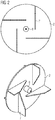
- Fig. 1 schematically a throw feeder is shown, in whose housing 1 a centrifugal wheel is arranged.
- the housing 1 has a central supply opening 5, through which fuel (see arrows) can be supplied from above. This fuel (see arrows) exits the housing 1 through the discharge opening 6 again.
- the fuel is transported through the blast wheel.
- This consists of a base plate 2, a hub 8 and wings.
- the left part of the figure shows a blast wheel with conventional wings 4, which have constant height over the entire length.
- the right part of the figure shows an inventive impeller with wings 7, the height of which increases from the inside to the outside.
- the height of the wing 7 increases from a height less than half the maximum height of the wing to the maximum height.
- the height of the wing 7 to the outer end of the wing 7 remains the same (maximum height).
- the hub 8 is here the same height as the inner end of the wing 7.
- what is essential is the ratio to the feed opening 5, the diameter - seen in the radial direction - ends before the wing 7 has reached its maximum height.
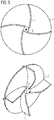
- Fig. 2 shows another possible embodiment of the blast wheel.
- four wings 7 are mounted on the base plate 2.
- the wings 7 close on its inside not on the hub 8, but are offset by about a third radius of the base plate 2 to the outside.
- the inner height of the wing is chosen as low as possible, approximately in the thickness of the sheet of the wings.
- the height of the wings rises along a straight line and reach after about 2/3 of the length of the wing 7, the maximum height.
- Fig. 3 shows a further embodiment of the blast wheel.
- four wings 7 are also arranged on the base plate 2, but the wings 7 are bent here and connect tangentially to the hub 8 at.
- the wings 7 have at their inner end a height of slightly less than half of the maximum height. The maximum height of the wings 7 is reached slightly after half the length of the wings.
- the material used for the wings is highly wear-resistant steel.
- the base plate 2 of the spinners shown here has a diameter of 450mm, the maximum height of the wings 7 is 85mm. However, these sizes must always be adapted to a specific system.
Landscapes
- Engineering & Computer Science (AREA)
- Mechanical Engineering (AREA)
- Chemical & Material Sciences (AREA)
- Combustion & Propulsion (AREA)
- General Engineering & Computer Science (AREA)
- Physics & Mathematics (AREA)
- Thermal Sciences (AREA)
- Structures Of Non-Positive Displacement Pumps (AREA)
- Supercharger (AREA)
Description
- Die Erfindung betrifft eine Feuerungsanlage mit Wurfbeschicker umfassend ein Schleuderrad mit mehreren, auf einer Grundplatte angeordneten Flügeln.
- Die Erfindung wird bei Feuerungsanlagen mit Schleuderrad-Wurfbeschickung eingesetzt. Der feste, kleinteilige Brennstoff wird dabei mit Hilfe des in einem Wurfbeschicker angeordneten Schleuderrades in den Feuerraum eingebracht. Durch Änderung der Drehzahl des Schleuderrades kann die Wurfweite eingestellt werden.
- In der Regel ist dabei das Schleuderrad waagrecht angeordnet, also die Drehachse des Schleuderrads steht senkrecht. Der Brennstoff wird von oben im Bereich der Nabe des Schleuderrades in das Gehäuse des Wurfbeschickers eingebracht und dann mit Hilfe der Flügel des Schleuderrades waagrecht nach außen und - durch Öffnungen des Wurfbeschickers - in den Feuerraum gefördert. Bisher wurden hierzu Schleuderräder verwendet, bei denen die Flügel eine konstante Höhe haben.
- Je nach Brennstoff ist das mit hoher Geschwindigkeit rotierende Schleuderrad jedoch einem hohen Verschleiß unterworfen. Die Brennstoffteilchen treffen bei Eintritt in den Wurfbeschicker nur auf die Oberkante der Flügel und werden daher nur stoßartig auf die erforderliche Austrittsgeschwindigkeit beschleunigt. Dadurch ergibt sich eine verlustreiche Übertragung der kinetischen Energie des Schleuderrades auf den Brennstoff, die mit hohem Verschleiß der Flügel des Schleuderrades verbunden ist.
- Eine Möglichkeit zur Verringerung des Verschleißes bestünde nun darin, die Drehzahl des Schleuderrades möglichst gering einzustellen. Dadurch wird aber die Wurfweite für den Brennstoff eingeschränkt und möglicherweise die optimale Brennstoffverteilung im Feuerraum nicht erreicht. Eine Feuerungsanlage mit Wurfbeschicker gemäß dem Oberbegriff des Anspruchs 1 ist aus
US4646637 bekannt. - Eine Aufgabe der Erfindung ist es nun, die Energieübertragung vom Schleuderrad auf den Brennstoff zu verbessern und damit den Verschleiß der Oberkanten der Flügel des Schleuderrades zu verringern.
- Die Aufgabe wird durch ein Schleuderrad nach Anspruch 1 gelöst, gemäß welchem die Höhe der Flügel in radialer Richtung zumindest in einem Bereich zunimmt und gegebenenfalls in einem oder mehreren übrigen Bereichen gleich bleibt, und die Höhe des Flügels am inneren Ende des Flügels kleiner als am äußeren Ende des Flügels ist.
- Mit anderen Worten nimmt also die Höhe des Flügels nach außen hin zu, sie kann über manche Bereiche auch gleichbleiben, sie darf aber in keinem Bereich abnehmen. Auf jeden Fall ist der Flügel innen weniger hoch als außen. Dadurch treffen die Brennstoffteilchen beim nach außen Wandern auf immer höhere Flügelbereiche, sie gleiten dabei an den Flügeln nach außen und werden kontinuierlich ohne Stöße beschleunigt.
- Als Folge davon wird die Verschleißbelastung von der inneren Flügeloberkante auf einen größere Fläche verteilt, sodass dadurch der Verschleiß an der Flügeloberkante verringert wird.
- Da weiters durch die Verringerung der Stöße eine bessere kinetische Energieübertragung vom Schleuderrad auf den Brennstoff erfolgt, kann die Drehzahl des Schleuderrades verringert werden.
- Eine mögliche Ausführungsform besteht darin, dass die Höhe der Flügel vom inneren Ende an in einem ersten Bereich ansteigt und anschließend in einem zweiten Bereich bis zum äußeren Ende gleich bleibt. Dies hat den Vorteil, dass im inneren Bereich der Flügel, wo in der Regel der Brennstoff zugeführt wird, der Brennstoff kontinuierlich an den aufsteigenden Oberkanten der Flügel beschleunigt wird und in zweiten Bereich, wo kein Brennstoff mehr direkt von oben zugeführt wird, weiter nach außen geleitet wird.
- Im Idealfall sollte die Höhe des Flügels am inneren Ende gleich Null sein. Falls dadurch die Festigkeit des Flügels nicht gewährleistet ist, kann der Flügel weiter außen verstärkt werden, etwa durch zusätzliche Bleche.
- Der erfindungsgemäße Effekt sollte sich aber auf jeden Fall auch einstellen, wenn die Höhe der Flügel am inneren Ende kleiner als die halbe maximale Höhe der Flügel ist.
- Natürlich kann der Effekt der Erfindung gesteigert werden, wenn die Flügel aus dem Bereich der Nabe der Grundplatte herausgerückt werden, da die Zuleitung des Brennstoffes ja in der Regel konzentrisch zur Nabe erfolgt. Diesbezüglich kann vorgesehen werden, dass die inneren Enden der Flügel einen Abstand zur Nabe der Grundplatte aufweisen.
- Die Anordnung und die Form der Flügel kann abgesehen von der Höhe der Flügel je nach Bedarf variiert werden: die Flügel können gerade oder gebogen sein; sie können radial von der Nabe nach außen verlaufen, sie können tangential zur Nabe angeordnet sein oder sie können weder direkt noch indirekt (über eine gedachte Verlängerung) die Nabe berühren. Die Flügel können direkt an die Nabe anschließen oder eben erst in einem Abstand von der Nabe beginnen.
- Die Flügel werden aber in der Regel immer bis zum Rand der Grundplatte reichen und sie sind längs der gesamten Unterkante fest mit der Grundplatte verbunden.
- Auch die Anzahl der Flügel hängt von der Brennstoffart und -menge ab. Gebräuchlich sind 2, 4 oder 6 Flügel.
- Wird das erfindungsgemäße Schleuderrad in einen Wurfbeschicker eingebaut, so umfasst dieser zumindest ein Gehäuse mit zumindest einer Zufuhröffnung für Brennstoff und zumindest einer Auswurföffnung für Brennstoff.
- Dabei ist eben zweckmäßigerweise eine Zufuhröffnung für Brennstoff vorgesehen, die konzentrisch zur Drehachse des Schleuderrades ist, sodass Brennstoff in Richtung der Drehachse auf das Schleuderrad aufgebracht werden kann.
- Ebenso kann eine umlaufende Auswurföffnung für Brennstoff vorgesehen sein, die normal zur Drehachse des Schleuderrades angeordnet ist, sodass Brennstoff in der Ebene des Schleuderrads aus dem Schleuderrad ausgeworfen werden kann.
- Damit der Brennstoff in jenem Bereich auftrifft, wo die Flügelhöhe gering ist, kann vorgesehen werden, dass die maximale Höhe der Flügel erst außerhalb des Durchmessers der Zuführöffnung erreicht wird.
- Ein Ausführungsbeispiel der Erfindung ist in den Figuren dargestellt und wird im Folgenden erläutert. Dabei zeigen:
-
Fig. 1 eine schematische Darstellung eines Wurfbeschickers mit Schleuderrad gemäß dem bisherigen Stand der Technik (links) sowie gemäß der Erfindung (rechts), -
Fig. 2 Ansicht und Draufsicht für ein erfindungsgemäßes Schleuderrad mit geraden Flügeln, -
Fig. 3 Ansicht und Draufsicht für ein erfindungsgemäßes Schleuderrad mit gebogenen Flügeln. - In
Fig. 1 ist schematisch ein Wurfbeschicker dargestellt, in dessen Gehäuse 1 ein Schleuderrad angeordnet ist. Das Gehäuse 1 weist eine zentrale Zufuhröffnung 5 auf, durch welche Brennstoff (siehe Pfeile) von oben zugeführt werden kann. Dieser Brennstoff (siehe Pfeile) tritt aus dem Gehäuse 1 durch die Auswurföffnung 6 wieder aus. - Der Brennstoff wird dabei durch das Schleuderrad befördert. Dies besteht aus einer Grundplatte 2, einer Nabe 8 und Flügeln. Der linke Teil der Figur zeigt ein Schleuderrad mit herkömmlichen Flügeln 4, die über die gesamte Länge konstante Höhe haben.
- Der rechte Teil der Figur zeigt ein erfindungsgemäßes Schleuderrad mit Flügeln 7, deren Höhe von innen nach außen zunimmt. In einem ersten Bereich nimmt die Höhe des Flügels 7 von einer Höhe, die kleiner als die halbe maximale Höhe des Flügels ist, bis zur maximalen Höhe zu. Im zweiten Bereich bleibt die Höhe des Flügels 7 bis zum äußeren Ende des Flügels 7 gleich (maximale Höhe). Die Nabe 8 ist hier gleich hoch wie das innere Ende des Flügels 7. Der erste Bereich des Flügels, der direkt an die Nabe 8 anschließt, reicht etwa bis zur Hälfte des Flügels. Wesentlich ist jedoch das Verhältnis zur Zuführöffnung 5, deren Durchmesser - in radialer Richtung gesehen - endet, bevor der Flügel 7 seine maximale Höhe erreicht hat.
- Durch das Zuführen des Brennstoffs von oben wird erreicht, dass die Brennstoffteilchen möglichst weit unter die Oberkante der Flügel bzw. sogar bis zur Grundplatte fallen. Die Brennstoffteilchen werden folglich nicht nur von der Flügeloberkante, sondern vom gesamten, in diesem Bereich niedrigeren Flügel erfasst und nach außen gefördert.
-
Fig. 2 zeigt eine andere mögliche Ausführung des Schleuderrads. Hier sind vier Flügel 7 auf der Grundplatte 2 angebracht. Die Flügel 7 schließen an ihrer Innenseite nicht an der Nabe 8 an, sondern sind etwa um einen Drittel Radius der Grundplatte 2 nach außen versetzt. Die innere Höhe des Flügel ist so niedrig wie möglich gewählt, etwa in der Dicke des Blechs der Flügel. Die Höhe der Flügel steigt längs einer Geraden an und erreich nach etwa 2/3 der Länge des Flügels 7 die maximale Höhe. -
Fig. 3 zeigt eine weitere Ausführungsform des Schleuderrads. Hier sind ebenfalls vier Flügel 7 auf der Grundplatte 2 angeordnet, allerdings sind die Flügel 7 hier gebogen und schließen tangential an die Nabe 8 an. Die Flügel 7 haben an ihrem inneren Ende eine Höhe von etwas weniger als der Hälfte der maximalen Höhe. Die maximale Höhe der Flügel 7 wird etwas nach der Hälfte der Länge der Flügel erreicht. - Als Werkstoff für die Flügel wird hoch verschleißfester Stahl verwendet.
- Die Grundplatte 2 der hier gezeigten Schleuderräder hat einen Durchmesser von 450mm, die maximale Höhe der Flügel 7 beträgt 85mm. Diese Größen sind jedoch immer für eine bestimmte Anlage anzupassen.
-
- 1
- Gehäuse des Wurfbeschickers
- 2
- Grundplatte
- 3
- Drehachse
- 4
- Flügel mit konstanter Höhe (Stand der Technik)
- 5
- Zufuhröffnung
- 6
- Auswurföffnung
- 7
- Flügel
- 8
- Nabe
Claims (6)
- Feuerungsanlage mit einem Wurfbeschicker umfassend zumindest ein Gehäuse (1) mit zumindest einer Zufuhröffnung (5) für Brennstoff, die konzentrisch zur Drehachse (3) des Schleuderrades ist, mit zumindest einer Auswurföffnung (6) für Brennstoff und mit einem Schleuderrad mit mehreren, auf einer Grundplatte (2) angeordneten Flügeln (7), wobei die Höhe der Flügel (7) in radialer Richtung zumindest in einem Bereich zunimmt und in einem oder mehreren übrigen Bereichen gleich bleibt, und die Höhe des Flügels (7) am inneren Ende des Flügels (7) kleiner als am äußeren Ende des Flügels ist, dadurch gekennzeichnet, dass die maximale Höhe der Flügel (7) erst außerhalb des Durchmessers der Zuführöffnung (5) erreicht wird.
- Wurfbeschicker nach Anspruch 1, dadurch gekennzeichnet, dass die Höhe der Flügel (7) vom inneren Ende an in einem ersten Bereich ansteigt und anschließend in einem zweiten Bereich bis zum äußeren Ende gleich bleibt.
- Wurfbeschicker nach einem der Ansprüche 1 oder 2, dadurch gekennzeichnet, dass die Höhe der Flügel (7) am inneren Ende gleich Null ist.
- Wurfbeschicker nach einem der Ansprüche 1 bis 3, dadurch gekennzeichnet, dass die Höhe der Flügel (7) am inneren Ende kleiner als die halbe maximale Höhe der Flügel (7) ist.
- Wurfbeschicker nach einem der Ansprüche 1 bis 4, dadurch gekennzeichnet, dass die inneren Enden der Flügel (7) einen Abstand zur Nabe (8) der Grundplatte (2) aufweisen.
- Wurfbeschicker nach einem der Ansprüche 1 bis 5, dadurch gekennzeichnet, dass eine umlaufende Auswurföffnung (6) für Brennstoff vorgesehen ist, die normal zur Drehachse (3) des Schleuderrades angeordnet ist, so dass Brennstoff in der Ebene des Schleuderrads aus dem Schleuderrad ausgeworfen werden kann.
Applications Claiming Priority (2)
| Application Number | Priority Date | Filing Date | Title |
|---|---|---|---|
| DE102008009683A DE102008009683B4 (de) | 2008-02-18 | 2008-02-18 | Schleuderrad eines Wurfbeschickers |
| PCT/EP2009/051619 WO2009103654A2 (de) | 2008-02-18 | 2009-02-12 | Schleuderrad eines wurfbeschickers |
Publications (2)
| Publication Number | Publication Date |
|---|---|
| EP2242950A2 EP2242950A2 (de) | 2010-10-27 |
| EP2242950B1 true EP2242950B1 (de) | 2018-10-17 |
Family
ID=40730608
Family Applications (1)
| Application Number | Title | Priority Date | Filing Date |
|---|---|---|---|
| EP09712060.4A Active EP2242950B1 (de) | 2008-02-18 | 2009-02-12 | Feuerungsanlage mit wurfbeschicker |
Country Status (6)
| Country | Link |
|---|---|
| US (1) | US20100319591A1 (de) |
| EP (1) | EP2242950B1 (de) |
| CN (1) | CN101946124A (de) |
| CA (1) | CA2715821A1 (de) |
| DE (1) | DE102008009683B4 (de) |
| WO (1) | WO2009103654A2 (de) |
Families Citing this family (7)
| Publication number | Priority date | Publication date | Assignee | Title |
|---|---|---|---|---|
| AT11833U1 (de) * | 2010-03-16 | 2011-05-15 | Wilde Andreas Ing | Vorrichtung zur wurfbeschickung eines rostes mit kleinstückeligem brennstoff |
| DE102011110078B4 (de) | 2011-08-20 | 2014-07-10 | Saxil-Werk Gmbh | Schüttgutsilo und das Verfahren zum Betreiben desselben. |
| CN110542114B (zh) * | 2018-05-28 | 2021-04-13 | 张金旗 | 生物质颗粒燃料抛料机 |
| US20200033008A1 (en) * | 2018-07-26 | 2020-01-30 | David Baker | Chip fuel feeder |
| CN110440280B (zh) * | 2019-08-01 | 2021-06-18 | 安徽德邦化工有限公司 | 一种高效节能锅炉 |
| CN112278870A (zh) * | 2020-08-14 | 2021-01-29 | 山东理工大学 | 一种气力吸送式分离增强装置 |
| CN114889990A (zh) * | 2022-03-21 | 2022-08-12 | 江西源生狼和药业有限公司 | 一种用于艾叶汁液收集加工装置 |
Citations (2)
| Publication number | Priority date | Publication date | Assignee | Title |
|---|---|---|---|---|
| DE8806500U1 (de) * | 1988-05-18 | 1988-07-07 | Teutrine, Annemarie, 4740 Oelde, De | |
| US4759156A (en) * | 1986-08-19 | 1988-07-26 | Acd, Inc. | Blast media transport and throwing wheel |
Family Cites Families (15)
| Publication number | Priority date | Publication date | Assignee | Title |
|---|---|---|---|---|
| FR781237A (fr) * | 1934-11-14 | 1935-05-11 | Cie Parisienne De Distrib De C | Chargeur-conducteur automatique de chaudières pour chauffage central |
| DE686716C (de) * | 1937-11-19 | 1940-01-15 | Alois Kulis | Beschickungsvorrichtung fuer Feuerungen |
| DE1577554A1 (de) * | 1966-02-15 | 1970-07-23 | Wilhelm Ahrens | Schleuderradvorrichtung fuer Strahlanlagen |
| US3610182A (en) * | 1969-10-03 | 1971-10-05 | Air Preheater | Sawdust feeder for incinerator |
| US3993225A (en) * | 1975-09-11 | 1976-11-23 | Mario Manni | Portable spreader for particulate material |
| FR2382388A1 (fr) * | 1977-03-03 | 1978-09-29 | Fouquet Dany | Appareillage de transport pour produits granuleux ou pulverulents |
| US4646637A (en) * | 1985-12-26 | 1987-03-03 | Cloots Henry R | Method and apparatus for fluidized bed combustion |
| US5134944A (en) * | 1991-02-28 | 1992-08-04 | Keller Leonard J | Processes and means for waste resources utilization |
| CA2066860C (en) * | 1992-04-22 | 1996-03-19 | Donald R. Kirby | Material spreading apparatus |
| DE19733946A1 (de) * | 1997-08-06 | 1999-02-11 | Ecm Ingenieur Unternehmen Fuer | Verfahren und Einrichtung zur thermischen Behandlung von Reststoffen |
| US6343986B1 (en) * | 1999-05-26 | 2002-02-05 | David A. Hofer | Combine straw and chaff spreader |
| US6517281B1 (en) * | 2000-05-19 | 2003-02-11 | Highway Equipment Company | Adjustable spinner for a particulate material spreader |
| DE10231522B4 (de) * | 2002-07-12 | 2007-04-05 | Maschinen- Und Antriebstechnik Gmbh & Co. Kg | Verfahren zur Förderung von Getreide und ähnlich hochwertigen Schüttgut, insbesondere der Landwirtschaft und eine Vorrichtung zur Durchführung des Verfahrens |
| US7331855B2 (en) * | 2005-07-15 | 2008-02-19 | Deere & Company | Wide-spread impeller spreader for harvesting combine |
| US7473171B1 (en) * | 2007-07-26 | 2009-01-06 | Cnh America Llc | Molded spreader disk |
-
2008
- 2008-02-18 DE DE102008009683A patent/DE102008009683B4/de not_active Expired - Fee Related
-
2009
- 2009-02-12 CN CN2009801055121A patent/CN101946124A/zh active Pending
- 2009-02-12 CA CA2715821A patent/CA2715821A1/en not_active Withdrawn
- 2009-02-12 US US12/866,747 patent/US20100319591A1/en not_active Abandoned
- 2009-02-12 EP EP09712060.4A patent/EP2242950B1/de active Active
- 2009-02-12 WO PCT/EP2009/051619 patent/WO2009103654A2/de active Application Filing
Patent Citations (2)
| Publication number | Priority date | Publication date | Assignee | Title |
|---|---|---|---|---|
| US4759156A (en) * | 1986-08-19 | 1988-07-26 | Acd, Inc. | Blast media transport and throwing wheel |
| DE8806500U1 (de) * | 1988-05-18 | 1988-07-07 | Teutrine, Annemarie, 4740 Oelde, De |
Also Published As
| Publication number | Publication date |
|---|---|
| WO2009103654A2 (de) | 2009-08-27 |
| CN101946124A (zh) | 2011-01-12 |
| WO2009103654A3 (de) | 2010-01-28 |
| CA2715821A1 (en) | 2009-08-27 |
| EP2242950A2 (de) | 2010-10-27 |
| US20100319591A1 (en) | 2010-12-23 |
| DE102008009683A1 (de) | 2009-08-20 |
| DE102008009683B4 (de) | 2010-10-21 |
Similar Documents
| Publication | Publication Date | Title |
|---|---|---|
| EP2242950B1 (de) | Feuerungsanlage mit wurfbeschicker | |
| EP0226987B1 (de) | Vorrichtung zum Klassieren von staubförmigen Schüttgütern | |
| EP1621522B1 (de) | Vorrichtung zum Wenden und Rückvermischen von Feuchtgut | |
| DE1954993C3 (de) | Zerstäuberrad zum Zerstäuben von stark schleißenden Materialien | |
| WO2016177358A1 (de) | Zerkleinerungsmaschine mit einem rotorsystem und verfahren zum zerkleinern von aufgabegut | |
| EP2905080A1 (de) | Rührwerkskugelmühle | |
| DE112013004298T5 (de) | Dreh-Sortiermaschine und Vertikalmühle | |
| EP2886198B1 (de) | Betriebsverfahren für eine Mahlkörpermühle und Mahlkörpermühe dafür | |
| WO2013083509A1 (de) | Siebvorrichtung zum sieben einer faserstoffsuspension | |
| EP3044138B1 (de) | Zellenradbunker zur förderung und vereinzelung von wenigstens einen schaft aufweisenden verbindungselementen | |
| EP3202290B1 (de) | Mahlwerk, mühle, kaffeezubereitungsvorrichtung mit mühle sowie mahlverfahren | |
| EP3335808A1 (de) | Sichtrad für einen zentrifugalkraft-windsichter | |
| EP2963243B1 (de) | Strömungsmaschine mit laufschaufeln mit in richtung der hinterkante abgesenkter schaufelspitze | |
| WO2013020976A1 (de) | Strukturierung der oberfläche der ogive eines geschosses | |
| DE102006017856A1 (de) | Zellenradschleuse für großes Schüttgut mit geringer Antriebsleistung | |
| EP1832386A1 (de) | Schleifrad zur spanabhebenden Bearbeitung von Gegenständen, insbesondere von natürlichen oder künstlichen Steinen | |
| EP1337344A1 (de) | Vollmantel-schneckenzentrifuge mit verteiler | |
| EP2372244B1 (de) | Vorrichtung zur Wurfbeschickung eines Rostes mit kleinstückeligem Brennstoff | |
| DE102012108539A1 (de) | Kohlenstaubmühle mit Biomassevermahlungsbereich | |
| DE102013101385A1 (de) | Pelletstaubabsaugung | |
| DE102010053172B4 (de) | Impeller zum Beschleunigen von Strahlmittel | |
| DE102007044888B4 (de) | Schleuderkanten-Verschleißeinheit | |
| EP3546871B1 (de) | Trennvorrichtung zum trennen eines festen stoffes aus einem förderstrom und verfahren zum warten einer solchen trennvorrichtung | |
| DE102010055800B4 (de) | Knetvorrichtung | |
| DE1778116C3 (de) | Trocknungstrommel mit zentralem Austrittsstutzen |
Legal Events
| Date | Code | Title | Description |
|---|---|---|---|
| PUAI | Public reference made under article 153(3) epc to a published international application that has entered the european phase |
Free format text: ORIGINAL CODE: 0009012 |
|
| 17P | Request for examination filed |
Effective date: 20100629 |
|
| AK | Designated contracting states |
Kind code of ref document: A2 Designated state(s): AT BE BG CH CY CZ DE DK EE ES FI FR GB GR HR HU IE IS IT LI LT LU LV MC MK MT NL NO PL PT RO SE SI SK TR |
|
| AX | Request for extension of the european patent |
Extension state: AL BA RS |
|
| DAX | Request for extension of the european patent (deleted) | ||
| RAP1 | Party data changed (applicant data changed or rights of an application transferred) |
Owner name: CHRISTOF INTERNATIONAL MANAGEMENT GMBH |
|
| 17Q | First examination report despatched |
Effective date: 20160127 |
|
| RAP1 | Party data changed (applicant data changed or rights of an application transferred) |
Owner name: CHRISTOF INTERNATIONAL MANAGEMENT GMBH |
|
| GRAP | Despatch of communication of intention to grant a patent |
Free format text: ORIGINAL CODE: EPIDOSNIGR1 |
|
| STAA | Information on the status of an ep patent application or granted ep patent |
Free format text: STATUS: GRANT OF PATENT IS INTENDED |
|
| INTG | Intention to grant announced |
Effective date: 20180627 |
|
| GRAS | Grant fee paid |
Free format text: ORIGINAL CODE: EPIDOSNIGR3 |
|
| GRAA | (expected) grant |
Free format text: ORIGINAL CODE: 0009210 |
|
| STAA | Information on the status of an ep patent application or granted ep patent |
Free format text: STATUS: THE PATENT HAS BEEN GRANTED |
|
| AK | Designated contracting states |
Kind code of ref document: B1 Designated state(s): AT BE BG CH CY CZ DE DK EE ES FI FR GB GR HR HU IE IS IT LI LT LU LV MC MK MT NL NO PL PT RO SE SI SK TR |
|
| REG | Reference to a national code |
Ref country code: GB Ref legal event code: FG4D Free format text: NOT ENGLISH |
|
| REG | Reference to a national code |
Ref country code: CH Ref legal event code: EP |
|
| REG | Reference to a national code |
Ref country code: IE Ref legal event code: FG4D Free format text: LANGUAGE OF EP DOCUMENT: GERMAN |
|
| REG | Reference to a national code |
Ref country code: DE Ref legal event code: R096 Ref document number: 502009015372 Country of ref document: DE Ref country code: AT Ref legal event code: REF Ref document number: 1054487 Country of ref document: AT Kind code of ref document: T Effective date: 20181115 |
|
| REG | Reference to a national code |
Ref country code: NL Ref legal event code: MP Effective date: 20181017 |
|
| REG | Reference to a national code |
Ref country code: LT Ref legal event code: MG4D |
|
| PG25 | Lapsed in a contracting state [announced via postgrant information from national office to epo] |
Ref country code: NL Free format text: LAPSE BECAUSE OF FAILURE TO SUBMIT A TRANSLATION OF THE DESCRIPTION OR TO PAY THE FEE WITHIN THE PRESCRIBED TIME-LIMIT Effective date: 20181017 |
|
| PG25 | Lapsed in a contracting state [announced via postgrant information from national office to epo] |
Ref country code: IS Free format text: LAPSE BECAUSE OF FAILURE TO SUBMIT A TRANSLATION OF THE DESCRIPTION OR TO PAY THE FEE WITHIN THE PRESCRIBED TIME-LIMIT Effective date: 20190217 Ref country code: FI Free format text: LAPSE BECAUSE OF FAILURE TO SUBMIT A TRANSLATION OF THE DESCRIPTION OR TO PAY THE FEE WITHIN THE PRESCRIBED TIME-LIMIT Effective date: 20181017 Ref country code: BG Free format text: LAPSE BECAUSE OF FAILURE TO SUBMIT A TRANSLATION OF THE DESCRIPTION OR TO PAY THE FEE WITHIN THE PRESCRIBED TIME-LIMIT Effective date: 20190117 Ref country code: LT Free format text: LAPSE BECAUSE OF FAILURE TO SUBMIT A TRANSLATION OF THE DESCRIPTION OR TO PAY THE FEE WITHIN THE PRESCRIBED TIME-LIMIT Effective date: 20181017 Ref country code: NO Free format text: LAPSE BECAUSE OF FAILURE TO SUBMIT A TRANSLATION OF THE DESCRIPTION OR TO PAY THE FEE WITHIN THE PRESCRIBED TIME-LIMIT Effective date: 20190117 Ref country code: ES Free format text: LAPSE BECAUSE OF FAILURE TO SUBMIT A TRANSLATION OF THE DESCRIPTION OR TO PAY THE FEE WITHIN THE PRESCRIBED TIME-LIMIT Effective date: 20181017 Ref country code: HR Free format text: LAPSE BECAUSE OF FAILURE TO SUBMIT A TRANSLATION OF THE DESCRIPTION OR TO PAY THE FEE WITHIN THE PRESCRIBED TIME-LIMIT Effective date: 20181017 Ref country code: PL Free format text: LAPSE BECAUSE OF FAILURE TO SUBMIT A TRANSLATION OF THE DESCRIPTION OR TO PAY THE FEE WITHIN THE PRESCRIBED TIME-LIMIT Effective date: 20181017 Ref country code: LV Free format text: LAPSE BECAUSE OF FAILURE TO SUBMIT A TRANSLATION OF THE DESCRIPTION OR TO PAY THE FEE WITHIN THE PRESCRIBED TIME-LIMIT Effective date: 20181017 |
|
| REG | Reference to a national code |
Ref country code: CH Ref legal event code: NV Representative=s name: ISLER AND PEDRAZZINI AG, CH |
|
| PG25 | Lapsed in a contracting state [announced via postgrant information from national office to epo] |
Ref country code: SE Free format text: LAPSE BECAUSE OF FAILURE TO SUBMIT A TRANSLATION OF THE DESCRIPTION OR TO PAY THE FEE WITHIN THE PRESCRIBED TIME-LIMIT Effective date: 20181017 Ref country code: GR Free format text: LAPSE BECAUSE OF FAILURE TO SUBMIT A TRANSLATION OF THE DESCRIPTION OR TO PAY THE FEE WITHIN THE PRESCRIBED TIME-LIMIT Effective date: 20190118 Ref country code: PT Free format text: LAPSE BECAUSE OF FAILURE TO SUBMIT A TRANSLATION OF THE DESCRIPTION OR TO PAY THE FEE WITHIN THE PRESCRIBED TIME-LIMIT Effective date: 20190217 |
|
| REG | Reference to a national code |
Ref country code: DE Ref legal event code: R097 Ref document number: 502009015372 Country of ref document: DE |
|
| PG25 | Lapsed in a contracting state [announced via postgrant information from national office to epo] |
Ref country code: IT Free format text: LAPSE BECAUSE OF FAILURE TO SUBMIT A TRANSLATION OF THE DESCRIPTION OR TO PAY THE FEE WITHIN THE PRESCRIBED TIME-LIMIT Effective date: 20181017 Ref country code: DK Free format text: LAPSE BECAUSE OF FAILURE TO SUBMIT A TRANSLATION OF THE DESCRIPTION OR TO PAY THE FEE WITHIN THE PRESCRIBED TIME-LIMIT Effective date: 20181017 Ref country code: CZ Free format text: LAPSE BECAUSE OF FAILURE TO SUBMIT A TRANSLATION OF THE DESCRIPTION OR TO PAY THE FEE WITHIN THE PRESCRIBED TIME-LIMIT Effective date: 20181017 |
|
| PLBE | No opposition filed within time limit |
Free format text: ORIGINAL CODE: 0009261 |
|
| STAA | Information on the status of an ep patent application or granted ep patent |
Free format text: STATUS: NO OPPOSITION FILED WITHIN TIME LIMIT |
|
| PG25 | Lapsed in a contracting state [announced via postgrant information from national office to epo] |
Ref country code: EE Free format text: LAPSE BECAUSE OF FAILURE TO SUBMIT A TRANSLATION OF THE DESCRIPTION OR TO PAY THE FEE WITHIN THE PRESCRIBED TIME-LIMIT Effective date: 20181017 Ref country code: RO Free format text: LAPSE BECAUSE OF FAILURE TO SUBMIT A TRANSLATION OF THE DESCRIPTION OR TO PAY THE FEE WITHIN THE PRESCRIBED TIME-LIMIT Effective date: 20181017 Ref country code: SK Free format text: LAPSE BECAUSE OF FAILURE TO SUBMIT A TRANSLATION OF THE DESCRIPTION OR TO PAY THE FEE WITHIN THE PRESCRIBED TIME-LIMIT Effective date: 20181017 |
|
| 26N | No opposition filed |
Effective date: 20190718 |
|
| PG25 | Lapsed in a contracting state [announced via postgrant information from national office to epo] |
Ref country code: SI Free format text: LAPSE BECAUSE OF FAILURE TO SUBMIT A TRANSLATION OF THE DESCRIPTION OR TO PAY THE FEE WITHIN THE PRESCRIBED TIME-LIMIT Effective date: 20181017 Ref country code: MC Free format text: LAPSE BECAUSE OF FAILURE TO SUBMIT A TRANSLATION OF THE DESCRIPTION OR TO PAY THE FEE WITHIN THE PRESCRIBED TIME-LIMIT Effective date: 20181017 Ref country code: LU Free format text: LAPSE BECAUSE OF NON-PAYMENT OF DUE FEES Effective date: 20190212 |
|
| REG | Reference to a national code |
Ref country code: BE Ref legal event code: MM Effective date: 20190228 |
|
| REG | Reference to a national code |
Ref country code: IE Ref legal event code: MM4A |
|
| PG25 | Lapsed in a contracting state [announced via postgrant information from national office to epo] |
Ref country code: IE Free format text: LAPSE BECAUSE OF NON-PAYMENT OF DUE FEES Effective date: 20190212 |
|
| PG25 | Lapsed in a contracting state [announced via postgrant information from national office to epo] |
Ref country code: FR Free format text: LAPSE BECAUSE OF NON-PAYMENT OF DUE FEES Effective date: 20190228 Ref country code: BE Free format text: LAPSE BECAUSE OF NON-PAYMENT OF DUE FEES Effective date: 20190228 |
|
| PG25 | Lapsed in a contracting state [announced via postgrant information from national office to epo] |
Ref country code: TR Free format text: LAPSE BECAUSE OF FAILURE TO SUBMIT A TRANSLATION OF THE DESCRIPTION OR TO PAY THE FEE WITHIN THE PRESCRIBED TIME-LIMIT Effective date: 20181017 |
|
| PG25 | Lapsed in a contracting state [announced via postgrant information from national office to epo] |
Ref country code: MT Free format text: LAPSE BECAUSE OF FAILURE TO SUBMIT A TRANSLATION OF THE DESCRIPTION OR TO PAY THE FEE WITHIN THE PRESCRIBED TIME-LIMIT Effective date: 20181017 |
|
| PG25 | Lapsed in a contracting state [announced via postgrant information from national office to epo] |
Ref country code: CY Free format text: LAPSE BECAUSE OF FAILURE TO SUBMIT A TRANSLATION OF THE DESCRIPTION OR TO PAY THE FEE WITHIN THE PRESCRIBED TIME-LIMIT Effective date: 20181017 |
|
| PG25 | Lapsed in a contracting state [announced via postgrant information from national office to epo] |
Ref country code: HU Free format text: LAPSE BECAUSE OF FAILURE TO SUBMIT A TRANSLATION OF THE DESCRIPTION OR TO PAY THE FEE WITHIN THE PRESCRIBED TIME-LIMIT; INVALID AB INITIO Effective date: 20090212 |
|
| REG | Reference to a national code |
Ref country code: AT Ref legal event code: PC Ref document number: 1054487 Country of ref document: AT Kind code of ref document: T Owner name: CHRISTOF GLOBAL IMPACT LTD., GB Effective date: 20211005 |
|
| REG | Reference to a national code |
Ref country code: GB Ref legal event code: 732E Free format text: REGISTERED BETWEEN 20211104 AND 20211110 |
|
| REG | Reference to a national code |
Ref country code: DE Ref legal event code: R081 Ref document number: 502009015372 Country of ref document: DE Owner name: CHRISTOF GLOBAL IMPACT LTD., GB Free format text: FORMER OWNER: CHRISTOF INTERNATIONAL MANAGEMENT GMBH, WIEN, AT |
|
| PGFP | Annual fee paid to national office [announced via postgrant information from national office to epo] |
Ref country code: CH Payment date: 20220218 Year of fee payment: 14 Ref country code: AT Payment date: 20220228 Year of fee payment: 14 |
|
| PG25 | Lapsed in a contracting state [announced via postgrant information from national office to epo] |
Ref country code: MK Free format text: LAPSE BECAUSE OF FAILURE TO SUBMIT A TRANSLATION OF THE DESCRIPTION OR TO PAY THE FEE WITHIN THE PRESCRIBED TIME-LIMIT Effective date: 20181017 |
|
| REG | Reference to a national code |
Ref country code: CH Ref legal event code: PL |
|
| REG | Reference to a national code |
Ref country code: AT Ref legal event code: MM01 Ref document number: 1054487 Country of ref document: AT Kind code of ref document: T Effective date: 20230212 |
|
| PG25 | Lapsed in a contracting state [announced via postgrant information from national office to epo] |
Ref country code: LI Free format text: LAPSE BECAUSE OF NON-PAYMENT OF DUE FEES Effective date: 20230228 Ref country code: CH Free format text: LAPSE BECAUSE OF NON-PAYMENT OF DUE FEES Effective date: 20230228 Ref country code: AT Free format text: LAPSE BECAUSE OF NON-PAYMENT OF DUE FEES Effective date: 20230212 |
|
| PGFP | Annual fee paid to national office [announced via postgrant information from national office to epo] |
Ref country code: DE Payment date: 20240228 Year of fee payment: 16 Ref country code: GB Payment date: 20240220 Year of fee payment: 16 |