EP2242419B1 - Vorrichtung und verfahren zur feststellung der blickrichtung - Google Patents
Vorrichtung und verfahren zur feststellung der blickrichtung Download PDFInfo
- Publication number
- EP2242419B1 EP2242419B1 EP08718518.7A EP08718518A EP2242419B1 EP 2242419 B1 EP2242419 B1 EP 2242419B1 EP 08718518 A EP08718518 A EP 08718518A EP 2242419 B1 EP2242419 B1 EP 2242419B1
- Authority
- EP
- European Patent Office
- Prior art keywords
- light
- eye
- grating
- diffractive
- substrate
- Prior art date
- Legal status (The legal status is an assumption and is not a legal conclusion. Google has not performed a legal analysis and makes no representation as to the accuracy of the status listed.)
- Active
Links
Images


Classifications
-
- G—PHYSICS
- G06—COMPUTING OR CALCULATING; COUNTING
- G06F—ELECTRIC DIGITAL DATA PROCESSING
- G06F3/00—Input arrangements for transferring data to be processed into a form capable of being handled by the computer; Output arrangements for transferring data from processing unit to output unit, e.g. interface arrangements
- G06F3/01—Input arrangements or combined input and output arrangements for interaction between user and computer
- G06F3/011—Arrangements for interaction with the human body, e.g. for user immersion in virtual reality
- G06F3/013—Eye tracking input arrangements
-
- A—HUMAN NECESSITIES
- A61—MEDICAL OR VETERINARY SCIENCE; HYGIENE
- A61B—DIAGNOSIS; SURGERY; IDENTIFICATION
- A61B3/00—Apparatus for testing the eyes; Instruments for examining the eyes
- A61B3/10—Objective types, i.e. instruments for examining the eyes independent of the patients' perceptions or reactions
- A61B3/113—Objective types, i.e. instruments for examining the eyes independent of the patients' perceptions or reactions for determining or recording eye movement
Definitions
- the present invention relates to the determination of the gaze direction of an eye.
- the gaze direction of a person may be used to select options displayed on a computer screen.
- an eye tracker device providing information on the gaze direction may be used, for example, as a pointing and selecting device instead of a computer mouse.
- the orientation of the eye may be determined based on the position of the pupil with respect to the position of the first Purkinje image.
- Patent application PCT/FI2006/050043 discloses an eye tracker device comprising a diffractive beam expander to provide two illuminating beams.
- the use of two Purkinje images makes the determination substantially independent of the distance between the eye and the tracker device.
- Said application discloses also that the eye tracker device may be used in combination with a virtual display unit, wherein said virtual display unit is arranged to display virtual images.
- An object of the present invention is to provide a device and a method for determining the gaze direction.
- a device for determining the gaze direction of an eye comprising:
- a method for determining the gaze direction of an eye comprising:
- the splitting of a single collimated beam by the in-coupling grating into at least two parts provides a simple and stable way to arrange the illumination of the eye.
- the device comprises also an optical engine and a further diffractive beam expander to display virtual images.
- the same out-coupling grating may be used for providing the illuminating beams and an virtual image.
- the device comprises also an optical engine and a further diffractive beam expander to display virtual images.
- the first diffractive beam expander of the eye tracker unit and the second diffractive beam expander for displaying virtual images may be implemented on the same substrate.
- the diffractive features of the output grating of the first diffractive beam expander may be substantially perpendicular to the diffractive features of the out-coupling grating of the second diffractive beam expander. Consequently, only minimum amount of illuminating light is coupled out of the substrate by the output grating of the second diffractive beam expander and/or the illuminating light coupled out of the substrate by the output grating of the second diffractive beam expander propagate in directions which do not disturb the determination of the gaze direction.
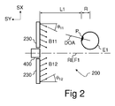
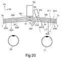
- the gaze direction GZD of the eye E1 may be expressed by the zenith angle ⁇ 1 and the azimuth angle ⁇ 1 of the gaze direction GZD with respect to the directions SX, SY, and SZ of a reference coordinate system.
- the direction SZ defines the vertical direction and the direction SX defines the horizontal direction of the reference coordinate system.
- the directions SX, SY, and SZ are orthogonal. See Fig. 11 a for the definition of the zenith and azimuth angles.
- the gaze direction GZD may be defined by a line passing through the center of the fovea FV and the principal point of the lens LNS of the eye E1.
- a reference line REF1 is parallel to the direction SY of the reference coordinate system.
- the position of the eye E1 may be moved in the directions SX, SY, and/or SZ.
- the reference line REF1 does not, in general, pass through the center O of the eye E1.
- Objects 1002, 1003 are located at a considerable or infinite distance from the eye E1.
- the objects 1002, 1003 may be physical objects (e.g. bodies), images displayed on a remote display screen, or images displayed by a virtual display.
- the angular coordinates of the objects 1002, 1003 are known with respect to a point C on the reference line REF1, and that the distance between the eye E1 and the objects 1002, 1003 is long when compared to the distance between the point C and the eye center O.
- the ratio of the distances may be e.g. greater than or equal to ten.
- the objects 1002, 1003 may be associated with gaze directions GZD. Consequently, by knowing the zenith angle ⁇ 1 and the azimuth angle ⁇ 1 of the gaze direction GZD, it may be determined which object the eye E1 is looking at, e.g. whether the eye E1 is looking at the star 1002 or the hexagon 1003.
- the actual form of the eye E1 is slightly non-spherical, but the form of the cornea may be approximated by a spherical surface.
- the center O of the eye E1 refers to the center of a best-fit sphere, said sphere being fitted with the corneal surface.
- the radius R of the eye E1 refers to the radius of said best-fit sphere.
- the direction DOA of the optical axis of the eye E1 is defined by a line passing through the center O of the eye E1 and the best fit center of the pupil P.
- the pupil is surrounded by the iris IRI.
- the determination of the best-fit center of the pupil P may also be determined partly or completely based on the location of the iris IRI.
- the gaze direction GZD deviates typically 3 - 5 degrees from the direction DOA of the optical axis.
- the relationship between the zenith and azimuth angles ⁇ 1', ⁇ 1' of the direction DOA and the zenith and azimuth angles ⁇ 1, ⁇ 1 of the gaze direction GZD may be established by e.g. calibration measurements. Said relationship may be expressed e.g. as regression equations.
- the zenith angle ⁇ 1' and the azimuth angle ⁇ 1' of the optical axis direction DOA may, in turn, be determined by an eye tracker device 200.
- the eye tracker device 200 may comprise one or more out-coupling gratings or grating portions 230 and an imaging unit 400.
- the out-coupling gratings 230 provide at least two substantially collimated light beams B11, B12, which are directed towards the eye E1, and which beams B11, B12 have different directions.
- the imaging unit 400 provides an image of the eye E1.
- the direction of the first illuminating beam B11 may be identified by the zenith angle ⁇ 11 and azimuth angle ⁇ 11 of said beam B11.
- the direction of the second illuminating beam B12 may be identified by the zenith angle ⁇ 12 and azimuth angle ⁇ 12 of said beam B11. Only the zenith angles ⁇ 11 and ⁇ 12 are shown in Fig. 2 .
- the beams B11 and B12 propagate in different directions, i.e. ⁇ 11 ⁇ ⁇ 12 and/or ⁇ 11 ⁇ ⁇ 12 .
- L1 denotes the distance between the imaging unit 400 and the pupil P of the eye E1.
- the imaging unit 400 comprises imaging optics to focus light onto an image sensor, which may be e.g. a charge coupled device (CCD) or a CMOS image sensor.
- the imaging unit 400 may comprise means for automatic focusing.
- light of the beam B11 is reflected from the corneal surface providing a plurality of reflected rays, which propagate in several different directions.
- a narrow fan of reflected light rays is received by the aperture of the imaging unit 400.
- Said fan is herein represented by a single ray NC, which is the weighted average of said fan.
- the ray NC is reflected from a reflection point N on the surface of the eye E1 to the principal point C of the imaging optics of the imaging unit 400.
- the second illuminating beam B12 (not shown in Fig. 3 ) is reflected from the corneal surface towards the imaging unit 400.
- the second illuminating beam B12 is reflected from a point M (not shown) on the surface of the eye E1 to the principal point C of the imaging optics of the imaging unit 400.
- Fig. 4 shows an image 401 of the eye E1 as acquired by the imaging unit 400.
- the first illuminating beam B11 is directed towards the eye E1 such that the reflection of the first beam B11 provides a first reflection spot G1 appearing in the image 401.
- the second illuminating beam B12 is directed towards the eye E1 such that the reflection of the second beam B12 provides a second reflection spot G2 appearing in the image 401.
- Image analysis algorithms may be applied to determine the coordinates X1, Z1, X2, Z2 of the reflection spots G1, G2, and the coordinates X3, Z3 of the pupil P in the image 401.
- the reflection spots G1, G2, i.e. the first Purkinje images should be distinguished from the other Purkinje images originating from the inside of the eye E1.
- the pupil refers to the circular transparent zone in the center of the iris IRI. It is the position of this black zone which can be determined by the camera 400 arranged to view the eye E1.
- the angular position of the first reflection spot G1 can be defined by a horizontal angle and a vertical angle between the reference direction REF1 and a line drawn from the point C of the imaging optics to the center of the reflection spot G1, i.e. to the point N shown in Fig. 3 .
- the angular positions of the reflection spots G1, G2 and the pupil P can be determined based on the acquired image 401.
- the relationship between the position of a pixel in the acquired image and the angular position of a feature imaged on said pixel may be calculated based on the known distance between the imaging optics and the image sensor. The relationship may also be determined experimentally in a test bench.
- the angular difference corresponding to the difference between the positions of the reflection spots G1, G2 establishes a yardstick, which makes the determination of the gaze direction substantially independent of the distance L1 between the imaging optics 400 and the eye E1.
- the algorithm for determining the gaze direction GZD and/or the direction DOA of the optical axis, based on the positions of the reflection spots G1, G2 and the pupil P1, has been described e.g. in the patent publication WO2007085682 A1 .
- the determination of the gaze direction GZD and/or the direction DOA of the optical axis may comprise:
- the pupil and the lens of the eye E1 are not on the surface of the eye E1, but inside the eye E1.
- the relationship between the gaze direction GZD and the direction DOA of the optical axis established by the above algorithm may be determined by calibration (See the discussion in the context of Fig. 21 ).
- the gaze direction GZD may be determined on the basis of the direction DOA of the optical axis of the eye E1 by using one or more regression equations.
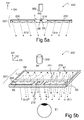
- an eye tracking device 200 may comprise a light source 350 and a diffractive beam expander 207 to provide at least two substantially collimated illuminating beams B11, B12.
- the eye tracking device 200 comprises also an imaging unit 400 and a data processing unit 550 (see Fig. 17 ).
- the light source 350 may be e.g. a laser which is adapted to emit e.g. infrared light.
- the imaging unit 400 is sensitive to the wavelength of the light source 350.
- the imaging unit 400 may comprise optical filters to reject light at other wavelengths.
- the diffractive beam expander may comprise an in-coupling grating 210 and out-coupling gratings 230.
- the gratings 230 may also be portions of the same grating.
- the gratings 210, 230 may be implemented on a substantially planar transparent substrate 7.
- the substrate 7 has a first substantially planar surface and a second substantially planar surface which is substantially parallel to said first planar surface.
- the substrate 7 is waveguiding, which means that in-coupled light may propagate within said substrate 7 such that said propagating light may be confined to said substrate 7 by total internal reflections (TIR).
- TIR total internal reflections
- the light source 350 may provide a narrow light beam B4.
- the narrow beam B4 impinges on the in-coupling grating 210 which diffracts light of said narrow beam into at least two different directions.
- the in-coupling grating acts as a diffractive beam splitter which provides a first in-coupled beam B5 and a second in-coupled beam B6.
- the beams B5 and B6 propagating within the substrate 7 are confined to the substrate 7 by total internal reflections.
- the first in-coupled beam B5 may substantially correspond to the reflective or transmissive diffraction order -1 and the second in-coupled beam B6 may substantially correspond to the reflective or transmissive diffraction order +1.
- the light of the beams B5 and B6 may be coupled out of the substrate 7 by the out-coupling gratings 230.
- the out-coupling gratings 230 provide the illuminating beams B11, B12.
- U.S. patent 6,580,529 discloses a diffractive beam expander for expanding a light beam in two dimensions.
- the diffractive beam expander 207 may further comprise a first expanding grating 221 and a second expanding grating 222.
- the first expanding grating 221 may provide a first internal beam B7 by diffracting light of the first in-coupled beam B5.
- the second expanding grating 221 may provide a second internal beam B8 by diffracting light of the second in-coupled beam B5.
- the internal beams B7, B8 have been expanded in the direction SX when compared to the original narrow beam B4 provided by the light source 350.
- the narrow beam B4 may be substantially perpendicular to the in-coupling grating 210.
- the out-coupling grating, out-coupling gratings, or out-coupling grating portions 230 may provide the illuminating beams B11, B12 by diffracting light of the internal beams B7, B8 out of the substrate 7.
- the illuminating beams B11, B12 may be directed such, and the tracker device 200 may be positioned with respect to the eye E1 such that the illuminating beams B11, B12 impinge on the corneal surface of the eye E1.
- the out-coupling grating 230 may provide beam expansion in the direction SZ. Consequently, the illuminating beams B11, B12 may now be expanded in the directions SX and SZ when compared to the dimensions of the narrow beam B4.
- the gratings 210, 221, 222 and 230 may have substantially linear diffractive features, e.g. a plurality of ridges and/or grooves.
- the diffractive features of the in-coupling grating 210 may be substantially parallel to the direction SZ.
- the diffractive features of the out-coupling grating 230 may be substantially parallel to the direction SX.
- the orientation of diffractive features in the expanding gratings may be selected such that the internal beams B7, B8 have different azimuth angles.
- diffraction of the beams B7, B8 at the out-coupling grating 230 provides the illuminating beams B11 and B12 which propagate in different directions, although the orientation of diffractive features at a first grating portion interacting with the beam B7 is the same as the orientation of diffractive features at a second grating portion interacting with the beam B8. Consequently, even the same portion of the grating 230 may be used to diffract light in the direction of the beam B11 and in the direction of the beam B12. Even the same point of the grating 230 may diffract light in the direction of the beam B11 and in the direction of the beam B12.
- the preferred distance in case of a goggle-type device may be e.g. in the range of 5 to 50 mm
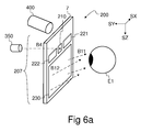
- Fig. 6a shows a three dimensional view of an eye tracker device 200.
- the imaging unit 400 may be arranged to monitor the eye E1 through the substrate 7 of the diffractive beam expander 207.
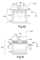
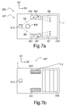
- Fig. 6b shows the positions of the gratings on the diffractive beam expander 207 of the eye tracker device 200 of Fig. 6a .
- Fig. 6c shows the orientation of diffractive features of the gratings 210, 221, 222, and 230 in the eye tracker device 200 of Fig. 6a .
- the gratings 210, 221, 222, and 230 may be in a plane defined by the directions SX and SZ.
- the diffractive features of the in-coupling grating 210 may be substantially parallel to the direction SZ.
- the diffractive features of the out-coupling grating 230 may be substantially parallel to the direction SZ.
- the grating periods d 221 and d 222 of the expanding gratings 221, 222 and the orientation angles ⁇ 221 , ⁇ 222 of the diffractive features of the expanding gratings 221, 222 may be selected such that the internal beams B7, B8 propagate in different azimuthal directions within the substrate 7.
- Fig. 7a shows another layout of the gratings 210, 221, 222, 230.
- Light B8 diffracted from the expanding grating 221 may impinge on the same grating 221 again, thereby providing an auxiliary beam B5' which propagates in the same direction as the original in-coupled beam B5.
- Light of the auxiliary beam B5' may provide further light rays which propagate in the direction of the internal beam B7.
- the expanding grating 222 may provide one or more auxiliary beams B6' in a similar fashion.
- the expanding gratings 221, 222 provide internal beams B7, B8 which have been expanded in the direction SZ.
- the narrow beam B4 emitted from the light source 350 may be inclined with respect to the in-coupling grating 210 so that the in-coupled beams B5, B6 do not propagate in opposite directions within the substrate 7.
- the azimuth angle of the beam B5 may be e.g. in the range of -90 to -45 degrees and The azimuth angle of the beam B6 may be e.g. in the range of 45 to 90 degrees
- the hatch patterns in Fig. 7b show schematically the orientation of the diffractive features in the gratings 210, 221, 222, 230.
- the orientation of the diffractive features in the gratings 221 and 222 may be selected e.g. according to eq.
- ⁇ 2 ⁇ d 221 - ⁇ d 210 ⁇ cos ⁇ + sin ⁇ B ⁇ 4 ⁇ sin ⁇ , where ⁇ B4 is the zenith angle of the beam B4 outside the substrate 7, p is the angle between the orientation of the diffractive features of the grating 210 and the diffractive features of the grating 221, ⁇ denotes the wavelength, d 221 denotes the grating period of the grating 221, and d 210 denotes the grating period of the grating 210.
- the angle p of the grating lines of 222 and 221 may be e.g. in the range of 10-30 degrees.
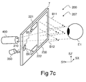
- Fig. 7c shows in a three dimensional view the eye tracker device 200 of Figs. 7a and 7b .
- the in-coupling grating may diffract light of the beam B4 into three or more different directions.
- the in-coupled beams B5 and B6 may be formed by diffractions in the diffraction orders -1 and +1, and a third beam B9 may be formed by diffraction in the zeroth diffraction order.
- the in-coupled beams B5 and B6 propagate within the substrate 7 towards the out-coupling grating 230 and/or towards expanding grating portions 221, 222, in order to form illuminating beams B11, B12 coupled out of the substrate 7.
- the third beam B9 corresponding to the zeroth diffraction order impinges on the opposite plane of the substrate at such an angle that it is not confined to the substrate 7 by total internal reflection.
- the beam B9 is transmitted through the substrate 7 and it is coupled out of the substrate 7.
- the in-coupling grating may diffract light of the beam B4 e.g. also in the diffraction order 2 in order to provide a further in-coupled beam B10 which may propagate within the substrate 7 towards the out-coupling grating 230 and/or towards a further expanding grating portions (not shown) in order to form a third illuminating beam (not shown), which is coupled out of the substrate 7 towards the eye.
- a further in-coupled beam may be provided also by diffraction in the diffraction order -2.
- the gaze direction may be determined using three or more different illuminating beams propagating in different directions.
- the gaze direction detecting algorithm developed for two beams may be used three times. The first time by using the a first illuminating beam and a second illuminating beam, the second time by using the first illuminating beam and a third illuminating beam, and the third time by using the second illuminating beam and the third illuminating beam.
- the zenith angles of the three determined gaze directions may be e.g. averaged in order to improve accuracy.
- the azimuth angles of the three determined gaze directions may be e.g. averaged in order to improve accuracy.
- Fig. 8a shows yet another layout of a diffractive beam expander 207 wherein the perimeter of the expanding gratings 221, 222 is inclined with respect to the direction of the diffractive features of the out-coupling grating 230.
- the narrow beam B4 emitted from the light source 350 may be inclined with respect to the in-coupling grating 210 to provide in-coupled beams B5, B6 which are inclined with respect to the direction of the diffractive features of the out-coupling grating 230.
- the elongated expanding gratings 221, 222 may be substantially aligned with the directions of the in-coupled beams B5, B6.
- the hatch patterns in Fig. 8b show the approximate orientation of the diffractive features in the gratings 210, 221, 222, 230 in the device of Fig. 8a .
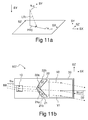
- Fig. 9 shows a virtual display device 100.
- the virtual display device 200 may comprise an optical engine 150 and a diffractive beam expander 107.
- the optical engine 150 may comprise a micro-display 170 and imaging optics 160 ( Fig. 10a ).
- the imaging optics 160 converts a real image 605 ( Fig. 10b ) formed by the micro-display 170 into a virtual image 1002 ( Fig. 19 ) which is observable through a viewing aperture 35 of the diffractive beam expander 107.
- the diffractive beam expander 107 may comprise an input grating 10, at least one beam-deflecting portion 21 a, 22a, at least one direction-restoring portion 21 b, 22b, and an output grating 30.
- the gratings 10, 30 and the portions 21a, 21b, 22a, 22b may be implemented on a substantially planar waveguiding substrate 7.
- the optical engine provides an input beam B0.
- the input beam B0 impinging on the input grating 10 may be coupled into the substrate 7 such that a corresponding in-coupled beam B1 propagates within said substrate towards the beam-deflecting portions 21 a, 22a.
- planar surfaces of the waveguiding substrate 7 are in planes defined by the directions SX and SZ.
- the restored beam V1 has been shifted with respect to the original in-coupled beam B1 and it propagates substantially in the same direction as the original in-coupled beam B1.
- a part of the in-coupled beam B1 may impinge on a second beam-deflecting grating portion 22a, which may diffract light towards the second direction-restoring grating portion 22b providing a second deflected light beam U2.
- the restoring portion 22b diffracts light of the beam U2 providing a second restored light beam V2.
- the second restored beam V2 has been shifted with respect to the original in-coupled beam B1 and it propagates substantially in the same direction as the original in-coupled beam B1.
- a part of the original in-coupled beam B1 may propagate within the substrate 7 without being diffracted by the portions 21 a, 21 b, 22a, 22b.
- the undiffracted part of the beam B1, the restored beam V1 and/or the restored beam V2 may together from an enlarged beam which propagates in the same direction as the original in-coupled beam B1.
- the enlarged beam may be subsequently coupled out of the substrate 7 by the output grating 30 to provide an output beam B2 which is expanded in two directions SX and SZ when compared to the dimensions of the input beam B0.
- the output beam B2 may be arranged to impinge on the eye E1 of an observer.
- the height H2 of the output beam B2 is greater than the height H0 of the input beam B0.
- the diffractive beam expander 107 provides beam expansion in the direction SZ.
- the width W2 of the output beam B2 may be greater than the width W0 of the input beam B0.
- the maximum height H2 and the maximum width W2 of the output beam B2 are limited by the dimensions of the viewing aperture 35.
- the height and the width of the input grating 10 may be selected to be substantially equal to or greater than the dimensions of the input beam B0, in order to maximize the efficiency of coupling light into the substrate 7.
- the gratings and the grating portions are diffractive elements.
- the gratings and the grating portions may be e.g. surface relief gratings implemented by molding or embossing on either of the planar surfaces 41, 42 ( Fig. 10a ).
- the profile of the gratings may be e.g. sinusoidal, binary rectangular or blazed. Yet, the profile of the gratings may be binary slanted or sinusoidal slanted.
- One or more gratings and/or portions may be embedded within the substrate 7.
- the gratings 10, 30 and the grating portions 21 a, 21 b, 22a, 22b may be in one or more planes defined by the directions SX and SY.
- the substrate 7 may comprise or consist of e.g. polycarbonate, polymethyl methacrylate (PMMA), or glass.
- the optical engine 150 may comprise a micro-display 170 and imaging optics 160.
- the imaging optics 160 may comprise one or more optical elements such as lenses, mirrors, prisms or diffractive elements.
- Light rays transmitted from a point PX1 of the micro-display 170 are substantially collimated by the imaging optics 160 to form parallel rays of light which constitute the beam B0 provided by the optical engine 150.
- the distance L3 between the micro-display 170 and the imaging optics 160 is set such that the pixels of the micro-display 170 are substantially at the focal distance of the imaging optics 160.
- a plurality of beams B0 are provided in order to display a virtual image, which consists of a plurality of pixels.
- Light of the input beam B0 is coupled into the waveguiding substrate 7 by the input grating 10.
- the in-coupled light propagates within the substrate 7 as the in-coupled beam B1.
- a part of the in-coupled beam B1 interacts with the first deflecting grating portion 21 a providing the deflected beam U1.
- a part of the deflected beam U1 interacts with the restoring grating portion 21 b providing the first restored beam V1.
- a part of the in-coupled beam B1 may remain undiffracted (not shown in Fig. 10a ).
- the output grating 30 diffracts the expanded output beam B2 towards the eye E1 of the observer.
- the enlarged light beams B2 provided by the diffractive beam expander 107 provide for a viewer an impression of a virtual image 1002 displayed at an infinite distance from the viewer.
- human viewers typically perceive that the displayed virtual image 1002 is only a few meters away from them, despite the infinite distance.
- the virtual image 1002 may be e.g. a star pattern as shown in Fig. 19 .
- the diffractive beam expander 107 may be mono-ocular, i.e. it may have only one output grating 30.
- the input grating 10, the output grating 30 and/or the grating portions 21 a, 21 b, 22a, 22b may be slanted or blazed surface relief gratings in order to maximize the efficiency of coupling light into the substrate 7 and out of the substrate 7.
- the diffractive beam expander 107 may comprise one or more optically absorbing structures 80 to eliminate stray light.
- the substrate 7 has a first substantially planar surface 41 and a second substantially planar surface 42 , which is substantially parallel to said first planar surface 41.
- the gratings 10, 30 and the portions 21 a, 21 b, 22a, 22b may be on the same planar surface 41, 42, or on opposite surfaces 41, 42.
- the input beam B0 may also be transmitted through the substrate 7 before impinging on the input grating 10.
- the micro-display 170 may be e.g. a liquid crystal display, an array of micromechanically movable mirrors, an array of light emitting diodes, or a unit comprising at least one movable and modulatable light-emitting point.
- Fig. 10b shows a real image 605 formed on the micro-display 170.
- the real image may be formed of light-emitting pixels or light-emitting points PX1.
- the optical engine 150 may also comprise a light-emitting point to provide a light beam and a beam-steering unit to rapidly vary the direction of said beam, wherein optical power provided by said light emitting point may be modulated based on the direction of said beam.
- the beam-steering unit may comprise e.g. one or more turning reflectors to change the direction of the beam.
- the optical engine 150 may also directly provide a virtual image by using a scanning method.
- Fig. 11 a shows the azimuth angle ⁇ LR1 of a light ray LR1 and the zenith angle ⁇ LR1 in the coordinate system defined by the directions SX-SY-SZ.
- the zenith angle is an angle between the direction of a light ray or beam and the direction -SY.
- the direction -SY is opposite the direction SY.
- the azimuth angle is an angle between the projection PRO and the direction SX, wherein said projection PRO is the projection of the direction of the light ray LR1 in a plane defined by the directions SX and SZ.
- the projection PRO forms the left side of the azimuth angle.
- the projection of the input beam B0 on the SX-SZ-plane has an azimuth angle ⁇ IN with respect to the direction SX.
- the projections of the in-coupled beam B1 and the restored beams V1, V2 have an azimuth angle with respect to the direction SX.
- the projection of the output beam B2 has an azimuth angle ⁇ OUT with respect to the direction SX.
- An intermediate grating 21 may comprise the deflecting portion 21 a and a restoring portion 21 b.
- a second intermediate grating 22 may comprise the deflecting portion 22a and a restoring portion 22b.
- the direction of the input beam B0 has a zenith angle ⁇ IN with respect to the direction -SY.
- the direction of the output beam B2 has a zenith angle ⁇ OUT with respect to the direction -SY.
- the orientation of the diffractive features of the gratings 10, 30 and the grating portions 21 a, 21 b, 22a, 22b and the grating periods of the gratings 10, 30 and the grating portions 21 a, 21 b, 22a, 22b may be selected such that the zenith angle ⁇ IN of the input beam B0 is substantially equal to the zenith angle ⁇ OUT of the output beam B2, and such that the azimuth angle ⁇ IN of the input beam B0 is substantially equal to the azimuth angle ⁇ OUT of the output beam B2.
- the output beam B2 may also be coupled out of the substrate 7 upwards in the direction SY.
- the orientation of the diffractive features of the gratings 10, 30 and the grating portions 21 a, 21b, 22a, 22b and the grating periods of the gratings 10, 30 and the grating portions 21 a, 21b, 22a, 22b may be selected such that the direction of the input beam B0 is substantially parallel to the direction of the output beam B2.
- the beam expander 107 may expand the exit pupil of the optical engine 150.
- the plurality of light beams B2 impinging on the eye E1 of the viewer create an impression of the same virtual image as when viewing the virtual image provided by the optical engine 150 without the beam expander 107.
- the beam expander 107 thanks to the beam expander 107, the viewer has a considerable freedom to move his eye E1 with respect to the virtual display unit 200 in the directions SX, SZ, and SY.
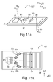
- the diffractive beam expander 107 may comprise an input grating 10, the deflecting portions 21 a, 22a, restoring portions 21 b, 22b, and an output grating 30.
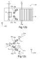
- the hatch patterns in Fig. 12b show the approximate orientation of the diffractive features of the gratings 10, 30 and the grating portions 21 a, 21 b, 22a, 22b.
- the gratings 10, 30 and the grating portions 21 a, 21 b, 22a, 22b may comprise substantially linear diffractive features, e.g. a plurality of microscopic grooves and/or ridges.
- the features F10 of the grating 10 and the features F30 of the grating 30 may be substantially parallel to the direction SZ.
- the grating period of the input grating 10 and the output grating 30 is d 0 .
- the portions 21 a, 21 b, 22a, 22b have substantially linear diffractive features F 21a , F 21b , F 22a , F 22b , which have grating periods d 21a , d 21b , d 22a , d 22b , and orientation angles ⁇ 21a , ⁇ 21b , ⁇ 22a , ⁇ 22b , respectively.
- An orientation angle defines herein the direction of the diffractive features with respect to the direction of the diffractive features of the grating 10.
- the first deflecting grating portion 21 a has a plurality of diffractive features F 21a , which have an angle ⁇ 21a with respect to the direction SZ.
- the first deflecting grating portion 21 a has a grating period d 21a .
- the second deflecting grating portion 22a has a plurality of diffractive features F 22a , which have an angle ⁇ 22a with respect to the direction SZ.
- the second deflecting grating portion 22a has a grating period d 22a .
- the first restoring grating portion 21 b has a plurality of diffractive features F 21b , which have an angle ⁇ 21b with respect to the direction SZ.
- the first restoring grating portion 21 b has a grating period d 21b .
- the second restoring grating portion 22b has a plurality of diffractive features F 22b , which have an angle ⁇ 22b with respect to the direction SZ.
- the second restoring grating portion 22b has a grating period d 22b .
- the grating periods of the grating portions 21 a, 21 b, 22a, 22b, 21 c, 22c may now be solved using eq. (2).
- the grating periods of the grating portions 21 a, 21 b, 22a, 22b, 21 c, 22c may be selected using eq. (2) such that diffraction is allowed only in the zeroth and in the first diffraction modes.
- the sign of the first order diffraction depends on the chosen coordinates.
- the angle ⁇ 21a between the direction of the diffractive features F 21a of said first deflecting grating portion 21 a and the direction SZ of the diffractive features F 10 of said input grating 10 may be in the range of 55 to 65 degrees.
- the orientation angle ⁇ 21a may be substantially equal to 60 degrees.
- the orientation angle ⁇ 22a may be substantially equal to 120 degrees, respectively.
- the first deflecting portion 21 a and the first restoring portion 21 b may have the same orientation of diffractive features and the same grating period.
- the second deflecting portion 22a and the second restoring portion 22b may have the same orientation of diffractive features and the same grating period.
- the first auxiliary reflecting portion 21 c (See Fig. 15a ) and the first restoring portion 21 b may have the same orientation of diffractive features and the same grating period.
- the second auxiliary reflecting portion 22c (see Fig. 15a ) and the second restoring portion 22b may have the same orientation of diffractive features and the same grating period.
- a line AX1 may intersect the input grating 10 and the output grating 30.
- the line AX may pass through the center of the input grating 10 and through the center of the output grating 30.
- the deflection portion 21a and the restoring portion 21b may be on different sides of the line AX1.
- the deflecting portion 22a and the restoring portion 22b may be on different sides of the line AX1. Consequently, the deflected beams U1 and U2 cross the line AX1.
- the line AX1 is, in fact, a projection of a plane PLN1.
- the deflection portion 21 a and the restoring portion 21 b may be on different sides of the plane PLN1 defined by the directions SX and SY.
- the deflecting portion 22a and the restoring portion 22b may be on different sides of the plane PLN1. Consequently, the deflected beams U1 and U2 pass through the plane PLN1.
- the diffractive beam expander 107 may comprise:
- Said first deflecting grating portion 21 a and said second restoring grating portion 22b may be on a first side of the reference plane PLN1, and said second deflecting grating portion 22a and said first restoring grating portion 21 b may be on a second side of said reference plane PLN1, said reference plane PLN1 being substantially perpendicular to the plane of said input grating 10.
- the diffractive beam expander 107 may comprise an input grating 10, an output grating 30, deflecting portions 21 a, 22a, and restoring portions 21 b, 22b.
- the beam expander 107 may have auxiliary deflecting portions 21c, 22c.
- the first auxiliary deflecting portion diffracts light of the in-coupled beam B1 towards the first restoring portion 21b.
- the second auxiliary deflecting portion diffracts light of the in-coupled beam B1 towards the second restoring portion 22b.
- the restoring portions 21b, 22b diffract the light again, providing auxiliary restored beams V1c and V2c, which are substantially parallel to the original in-coupled beam B1 and the restored beams V1 and V2.
- the portions 21 a, 22b and 22c may be on a first side of a plane PLN1, and the portions 22a, 21 b, and 21 c may be on a second side of said plane PLN, said plane PLN1 being substantially perpendicular to the plane of the input grating 10.
- the line AX1 is the projection of said plane PLN1 (see Fig. 14 ).
- the substrate 7 of Fig. 15a may also comprise an in-coupling grating 210, expanding gratings 221, 222, and an out-coupling grating 230 for providing the illuminating light beams B11, B12 needed for eye tracking.
- the gratings 210, 221, 222 and 230 form a second diffractive beam expander 207 which splits a narrow collimated beam impinging on the in-coupling grating 210 into at least two parts and provides the two enlarged beams B11, B12, which propagate in different directions (see also Figs. 5b and 7c ).
- the hatching in Fig. 15c shows, by ways of example, the orientation of the diffractive features in the gratings and grating portions 10, 21 a, 21 b, 21 c, 22a, 22b, 22c, 30, 210, 221, 222, and 230.
- the diffractive features of the output grating 30 may be substantially parallel to the diffractive features of the out-coupling grating 230.
- the output grating 30 may also have substantially the same grating period as the out-coupling grating 230. Consequently, the output grating 30 and the out-coupling grating 230 may constitute together a single grating 30.
- a common portion CPR of the output grating 30 and the out-coupling grating 230 may simultaneously contribute to the illuminating beams B11, B12 as well as to the plurality of beams B2 corresponding to the displayed virtual image.
- the imaging unit 400 may be arranged to monitor the eye E1 through a portion of the substrate 7 which does not comprise diffractive features. Such an unobstructed portion may reside e.g. between the grating portions 21 a and 21 b.
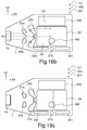
- Figs. 16a , 16b and 16c show another way to implement the gratings and the grating portions 10, 21 a, 21 b, 22a, 22b, 30, 210, 221, 222, 230 on the same substrate 7.
- the hatching in Fig. 16c shows the orientation of the diffractive features in the gratings and grating portions 10, 21a, 21b, 21c, 22a, 22b, 22c, 30, 210, 221, 222, and 230.
- the diffractive features of the output grating 30 may be substantially perpendicular to the diffractive features of the out-coupling grating 230.
- the output grating 30 couples a minimum amount of illuminating light out of the substrate 7 although the internal beams B7 and B8 may impinge on the output grating 30 several times before reaching the actual output grating 230.
- Light beams, in particular infrared beams, which would illuminate the eye E1 from undesired directions can be substantially avoided.
- the output grating 30 may at least partly transparent to infrared light.
- the imaging unit 400 may be arranged to monitor the eye e.g. through the output grating 30.
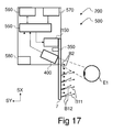
- an eye tracker device 200 may comprise an imaging unit 400 to acquire an image of the eye E1, a light source 350 to provide a first substantially collimated light beam B0, a first diffractive beam expander 207 to expand the light of said first light beam B0 and to provide at least two enlarged substantially collimated illuminating beams B11, B12.
- the eye tracker device 200 may comprise a data processing unit 550 to determine the gaze direction GZD on the basis of the image 401 acquired by the imaging unit 400.
- the eye tracker device 200 may comprise a command interface 570 and a communications unit 560.
- the command interface 570 may be a push-button device, joystick or keyboard, which allows a user to send commands to the device 700.
- the command interface 570 may also be a voice command device or a gesture recognition device.
- the communications unit 560 may be an interface module for communicating with a computer or mobile device.
- the communications unit 560 may also be an optical or radio frequency transmitter/receiver, which allows communication via internet or radio network.
- the eye tracking device 200 may comprise a position sensor 580 to determine the position of the device 200 with respect to at least one external reference.
- the external reference may be e.g. a real object or an image displayed on a screen.
- the position sensor 580 may be e.g. a camera.
- the position sensor may also be an inertial position sensor comprising one or more gyroscopes and/or accelerometers.
- a virtual display device 500 may comprise an optical engine 150 and a further diffractive beam expander 107.
- the first diffractive beam expander 207 for tracking the gaze direction and the second diffractive beam expander 107 for displaying virtual images may be implemented on the same substrate 7.
- the eye tracking device 200 or the virtual display device 500 may be a compact, portable and lightweight device.
- the second diffractive beam expander 107 may be arranged to expand the exit pupil of the optical engine 150 such as an expander disclosed in the patent application US 2006/0126182 .
- the second diffractive beam expander 107 may be arranged to expand the exit pupil of the optical engine 150 such as an expander disclosed in the patent application PCT/FI2007/050322 .
- the second diffractive beam expander 107 may be arranged to expand the exit pupil of the optical engine 150 such as an expander disclosed in the patent application PCT/FI2006/050590 .
- the same substrate 7 may comprise gratings or grating areas 10, 21, 21', 30, 30', 210, 221, 222, 230 to implement a bi-ocular beam expander 107 suitable for displaying virtual images to both eyes of a viewer and a bi-ocular beam expander 207 for providing the illuminating beams B11, B12 in order to track the gaze direction of at least one eye of said viewer.
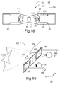
- the bi-ocular beam expander 107 may be used to implement a virtual display device 500 shown in Fig. 19 .
- the output beams B2 provided by the output gratings 30, 30' to the eyes E1, E2 of a viewer provide for the viewer an impression of a virtual image 1002 displayed at an infinite distance from the viewer.
- the virtual image 1002 may be e.g. a star pattern as shown in Fig. 19 , corresponding to a real image 605 generated by a micro-display 170 ( Fig. 10b ).
- the virtual image 1002 may be e.g. graphics and/or text.
- the virtual display device 500 may further comprise the eye tracer unit 200 to monitor the gaze direction of the eye E1.
- the display device of Fig. 19 may further comprise earpieces 589 which may be positioned on the ears of the viewer in order to facilitate positioning of the virtual display device 500 in front of the eyes E1, E2 of the viewer.
- the display device 500 may also be attached to a headgear, e.g. to a helmet.
- the virtual display device 500 may comprise stacked beam expanders 107 in order to display color images.
- a first diffractive beam expander 107 implemented on a first substrate 7 may be arranged to display red components B2R of a virtual image.
- a second diffractive beam expander 107 implemented on a second substrate 7b may be arranged to display green B2G and blue B2B components of the virtual image through the first beam expander.
- a third diffractive beam expander 107 implemented on a third substrate 7' may be arranged to display red components B2R of a virtual image to the left eye of a viewer.
- a fourth diffractive beam expander 107 implemented on a fourth substrate 7b' may be arranged to display green B2G and blue B2B components of the virtual image through the third beam expander.
- Each of the beam expanders 107 may have its own input grating 10, 10b, 10', 10b' and output grating 30, 30b, 30', 30b'.
- a fifth beam expander 207 may be implemented on the first substrate 7 for providing the illuminating beams B11, B12.
- the light source 350 may also be on the same side of the substrate 7 as the monitored eye E1.
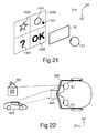
- the eye E1 of a viewer may see a displayed virtual image 1000 through the output aperture 35 of the virtual display 100, 500.
- the virtual image 1000 may comprise displayed objects 1002, 1003, 1004, 1005, for example a star 1002, a hexagon 1003, a symbol "OK” 1005 and a question mark "?” 1004.
- the objects or locations of the virtual image 1000 are advantageously associated with gaze directions.
- the eye E1 when the eye E1 is looking at an object or location decided by the viewer, it can be determined on the basis of the gaze direction which object or location the eye E1 is looking at.
- each object or location may be associated with an option, and the viewer may select an option by looking at the respective object or location.
- the user may confirm the selection e.g. by pushing a button of the command interface 570 ( Fig. 17 ).
- the user may also confirm the selection by blinking his eye, or by staring at a predetermined object or location for an extended period.
- the user may choose between options represented by the object 1002 (star) or the object 1003 (hexagon), by directing his gaze. If the hexagon is chosen, the device 500 may provide visual feedback by blinking after the selection. The user may confirm the selection e.g. by looking at the symbol "OK”. Yet, the user may ask for further information by looking at the question mark "?".
- the objects 1002, 1003, 1004, 1005 of the virtual image 1000 may be associated with the gaze directions in the software and/or hardware level by e.g. by converting the pixel coordinates of the objects into angular coordinates.
- the angular coordinates of a displayed object may be compared with the gaze direction to determine whether the user is looking at said object or not.
- a visible or invisible cursor 1001 may be adapted to move over the virtual image 1000, following the determined gaze direction of the eye E1.
- the cursor 1001 helps the user to understand that the tracker device is really following his gaze. In other words, the cursor 1001 provides visual feedback to the user.
- the detected gaze direction may be calibrated e.g. by moving a blinking cursor 1001 over the virtual image 1000, and asking the user to look at the cursor 1001. Further, the user may be asked to push the button of the command interface 570 when he is actually looking at the cursor 1001.
- the user may also view physical objects 901 (a house), 902 (a car) through the beam expander 107, 207.
- the position of the device 500 may be fixed with respect to the objects 901, 902, or the device 500 may comprise a position sensor 580 ( Fig. 17 ) to monitor the position of the device 500 with respect to at least one object 901, 902.
- the objects 901, 902, the locations of the objects, and/or the features of a landscape may be associated with the gaze directions. For example, it may be determined whether the user is looking at the house 901 or the car 902. Further, the objects 901, 902 may be associated with options such that an option may be selected by looking at the respective object.
- the device 200, 500 may further comprise e.g. a data processing unit, memory and communications unit to provide access to a mobile telephone network, internet or local area network.
- the device 200, 500 may be, for example, selected from the following list: a display module connectable to a further device, portable device, device with wireless telecommunicating capabilities, imaging device, mobile phone, gaming device, music recording/playing device (based on e.g. MP3-format), remote control transmitter or receiver, navigation instrument, measuring instrument, target finding device, aiming device, navigation device, personal digital assistant (PDA), communicator, portable internet appliance, hand-held computer, accessory to a mobile phone.
- PDA personal digital assistant
Landscapes
- Engineering & Computer Science (AREA)
- Life Sciences & Earth Sciences (AREA)
- Health & Medical Sciences (AREA)
- General Engineering & Computer Science (AREA)
- Human Computer Interaction (AREA)
- Physics & Mathematics (AREA)
- Theoretical Computer Science (AREA)
- Biomedical Technology (AREA)
- Biophysics (AREA)
- Ophthalmology & Optometry (AREA)
- General Physics & Mathematics (AREA)
- Heart & Thoracic Surgery (AREA)
- Medical Informatics (AREA)
- Molecular Biology (AREA)
- Surgery (AREA)
- Animal Behavior & Ethology (AREA)
- General Health & Medical Sciences (AREA)
- Public Health (AREA)
- Veterinary Medicine (AREA)
- Eye Examination Apparatus (AREA)
Claims (15)
- Vorrichtung (200, 500), aufweisend:- eine Abbildungseinheit (400), die konfiguriert ist, ein Bild (401) eines Auges (E1) zu erlangen,- ein im Wesentlichen planares Wellenleitungssubstrat (7),- eine Lichtquelle (350), die konfiguriert ist, einen ersten Lichtstrahl (B4) bereitzustellen, wobei der erste Lichtstrahl (B4) im Wesentlichen kollimiert ist,- ein einkoppelndes Gitter (210), das konfiguriert ist, Licht des Lichtstrahls (B4) in das Substrat (7) abzulenken und einen ersten eingekoppelten Strahl (B5) und einen zweiten eingekoppelten Strahl (B6) zu bilden, die sich innerhalb des Substrats (7) in unterschiedlichen Richtungen ausbreiten,- einen ersten expandierenden Gitterabschnitt (221), der konfiguriert ist, einen ersten expandierten internen Strahl (B7) durch Ablenken von Licht des ersten eingekoppelten Strahls (B5) bereitzustellen,- einen zweiten expandierenden Gitterabschnitt (222), der konfiguriert ist, einen zweiten expandierten internen Strahl (B8) durch Ablenken von Licht des zweiten eingekoppelten Strahls (B6) bereitzustellen,- einen ersten auskoppelnden Gitterabschnitt (230), der konfiguriert ist, einen ersten im Wesentlichen kollimierten Beleuchtungsstrahl (B11) durch Ablenken von Licht des ersten expandierten internen Strahls (B7) aus dem Substrat (7) zu bilden,- einen zweiten auskoppelnden Gitterabschnitt (230), der konfiguriert ist, einen zweiten im Wesentlichen kollimierten Beleuchtungsstrahl (B12) durch Ablenken von Licht des zweiten expandierten internen Strahls (B8) aus dem Substrat (7) zu bilden, wobei die Beleuchtungsstrahlen (B11, B12) unterschiedliche Richtungen aufweisen, sodass der erste Beleuchtungsstrahl (B11) eine erste Reflexionsstelle bereitstellt, wenn Licht von der Oberfläche des Auges (E1) reflektiert wird, und der zweite Beleuchtungsstrahl (B12) eine zweite Reflexionsstelle (G2) bereitstellt, wenn Licht von der Oberfläche des Auges (E1) reflektiert wird, wobei die Reflexionsstellen in dem Bild (401) erscheinen, und- eine Datenverarbeitungseinheit (550), die konfiguriert ist, die Blickrichtung (GZD) des Auges (E1) in Bezug auf die Vorrichtung (200, 500) basierend auf der Position der ersten Reflexionsstelle (G1) in dem Bild (401), auf der Position der zweiten Reflexionsstelle (G2) in dem Bild (401), auf der Position der Pupille (P) und/oder der Iris (IRI) des Auges (E1) in dem Bild (401) und auf den Richtungen der Beleuchtungslichtstrahlen (B11, B12) zu bestimmen.
- Vorrichtung (200, 500) nach Anspruch 1, wobei der erste eingekoppelte Strahl (B5) im Wesentlichen der reflektierenden oder lichtdurchlässigen Gitterordnung -1 entspricht und der zweite eingekoppelte Strahl (B6) im Wesentlichen der reflektierenden oder lichtdurchlässigen Gitterordnung +1 entspricht.
- Vorrichtung (200, 500) nach Anspruch 2, wobei das einkoppelnde Gitter (210) ferner konfiguriert ist, Licht des Lichtstrahls (B4) in der Gitterordnung 2 oder -2 abzulenken, um einen dritten eingekoppelten Strahl (B10) zu bilden, der sich innerhalb des Substrats (7) ausbreitet.
- Vorrichtung (200, 500) nach einem der vorstehenden Ansprüche 1 bis 3, wobei Ablenkmerkmale des ersten auskoppelnden Gitterabschnitts (230) im Wesentlichen parallel zu Ablenkmerkmalen des zweiten auskoppelnden Gitterabschnitts (230) sind.
- Vorrichtung (200, 500) nach Anspruch 4, wobei der erste auskoppelnde Gitterabschnitt (230) den zweiten auskoppelnden Gitterabschnitt (230) überlappt.
- Vorrichtung (200, 500) nach irgendeinem der vorstehenden Ansprüche 1 bis 5, ferner aufweisend eine Positionsdetektiereinheit (580), um die Position der Vorrichtung (500) in Bezug auf mindestens einen externen Bezug (901) zu bestimmen.
- Vorrichtung (200, 500) nach irgendeinem der vorstehenden Ansprüche 1 bis 6, die angepasst ist, ein reales Objekt (901) oder einen Ort mit einer Blickrichtung zu verbinden.
- Vorrichtung (500) nach irgendeinem der vorstehenden Ansprüche 1 bis 7, ferner aufweisend eine optische Engine (150), die konfiguriert ist, mindestens einen Lichtstrahl (B0) und einen ablenkenden Strahlaufweiter (107) bereitzustellen, um den mindestens einen Lichtstrahl (B0) zu expandieren, sodass ein virtuelles Bild (1001) durch eine Schauöffnung (35) des ablenkenden Strahlaufweiters (107) visuell beobachtbar ist.
- Vorrichtung (500) nach Anspruch 8, wobei ein Ausgangsgitterabschnitt (30) des ablenkenden Strahlaufweiters (107) den ersten auskoppelnden Abschnitt (230) überlappt.
- Vorrichtung (500) nach Anspruch 8, wobei ein Ausgangsgitterabschnitt (30) des ablenkenden Strahlaufweiters (107) im Wesentlichen zu dem ersten auskoppelnden Abschnitt (230) senkrecht ist.
- Vorrichtung (500) nach irgendeinem der vorstehenden Ansprüche 8 bis 10, die angepasst ist, ein virtuelles Objekt (1001) mit einer Blickrichtung zu verbinden.
- Verfahren, aufweisend:- Erlangen eines Bildes (401) eines Auges (E1) unter Verwendung einer Abbildungseinheit (400),- Bereitstellen eines im Wesentlichen kollimierten ersten Lichtstrahls (B4) unter Verwendung einer Lichtquelle (350),- Ablenken des Lichtes des ersten Lichtstrahls (B4) unter Verwendung eines einkoppelnden Gitters (210), um einen ersten eingekoppelten Strahl (B5) und einen zweiten eingekoppelten Strahl (B6) zu bilden, die sich in unterschiedlichen Richtungen innerhalb eines im Wesentlichen planaren Wellenleitungssubstrats (7) ausbreiten,- Ablenken des Lichtes des ersten eingekoppelten Strahls (B5) durch einen ersten expandierenden Gitterabschnitt (221), um einen ersten expandierten internen Strahl (B7) bereitzustellen, der sich innerhalb des Substrats (7) ausbreitet,- Ablenken des Lichtes des zweiten eingekoppelten Strahls (B6) durch einen zweiten expandierenden Gitterabschnitt (222), um einen zweiten expandierten internen Strahl (B8) bereitzustellen, der sich innerhalb des Substrats (7) ausbreitet,- Ablenken des Lichtes des ersten expandierten internen Strahls (B7) durch einen ersten auskoppelnden Gitterabschnitt (230) aus dem Substrat (7), um einen ersten im Wesentlichen kollimierten Beleuchtungsstrahl (B11) zu bilden,- Ablenken des Lichtes des zweiten expandierten internen Strahls (B8) durch einen zweiten auskoppelnden Gitterabschnitt (230) aus dem Substrat (7), um einen zweiten im Wesentlichen kollimierten Beleuchtungsstrahl (B12) zu bilden, wobei die Beleuchtungsstrahlen (B11, B12) unterschiedliche Richtungen aufweisen, sodass der erste Beleuchtungsstrahl (B11) eine erste Reflexionsstelle (G1) bereitstellt, wenn Licht von der Oberfläche des Auges (E1) reflektiert wird, und der zweite Beleuchtungsstrahl (B12) eine zweite Reflexionsstelle (G2) bereitstellt, wenn Licht von der Oberfläche des Auges (E1) reflektiert wird, wobei die Reflexionsstellen in dem Bild (401) erscheinen, und- Bestimmen der Blickrichtung (GZD) des Auges (E1) basierend auf der Position der ersten Reflexionsstelle (G1) in dem Bild (401), auf der Position der zweiten Reflexionsstelle (G2) in dem Bild (401), auf der Position der Pupille (P) und/oder Iris (IRI) des Auges (E1) in dem Bild (401) und auf den Richtungen der beleuchtenden Lichtstrahlen (B11, B12).
- Verfahren nach Anspruch 12, wobei Ablenkmerkmale des ersten auskoppelnden Gitterabschnitts (230) im Wesentlichen parallel zu Ablenkmerkmalen des zweiten auskoppelnden Gitterabschnitts (230) sind.
- Verfahren nach Anspruch 13, wobei der erste auskoppelnde Gitterabschnitt (230) den zweiten auskoppelnden Gitterabschnitt (230) überlappt.
- Verfahren nach irgendeinem der Ansprüche 12 bis 14, ferner aufweisend:- Bereitstellen von mindestens einem Lichtstrahl (B0) durch Verwenden der optischen Engine (150),- Anzeigen eines virtuellen Bildes (1001) durch Expandieren des mindestens einen Lichtstrahls (B0) unter Verwendung eines ablenkenden Strahlaufweiters (107), wobei das virtuelle Bild (100) durch eine Schauöffnung (35) des ablenkenden Strahlaufweiters (107) beobachtbar ist.
Priority Applications (1)
| Application Number | Priority Date | Filing Date | Title |
|---|---|---|---|
| PL08718518T PL2242419T3 (pl) | 2008-02-14 | 2008-02-14 | Urządzenie i sposób określania kierunku spojrzenia |
Applications Claiming Priority (1)
| Application Number | Priority Date | Filing Date | Title |
|---|---|---|---|
| PCT/FI2008/050065 WO2009101238A1 (en) | 2008-02-14 | 2008-02-14 | Device and method for determining gaze direction |
Publications (3)
| Publication Number | Publication Date |
|---|---|
| EP2242419A1 EP2242419A1 (de) | 2010-10-27 |
| EP2242419A4 EP2242419A4 (de) | 2013-03-13 |
| EP2242419B1 true EP2242419B1 (de) | 2016-01-13 |
Family
ID=40956684
Family Applications (1)
| Application Number | Title | Priority Date | Filing Date |
|---|---|---|---|
| EP08718518.7A Active EP2242419B1 (de) | 2008-02-14 | 2008-02-14 | Vorrichtung und verfahren zur feststellung der blickrichtung |
Country Status (6)
| Country | Link |
|---|---|
| US (1) | US8494229B2 (de) |
| EP (1) | EP2242419B1 (de) |
| CN (1) | CN101945612B (de) |
| ES (1) | ES2562063T3 (de) |
| PL (1) | PL2242419T3 (de) |
| WO (1) | WO2009101238A1 (de) |
Cited By (2)
| Publication number | Priority date | Publication date | Assignee | Title |
|---|---|---|---|---|
| US10248197B2 (en) | 2017-04-27 | 2019-04-02 | Imam Abdulrahman Bin Faisal University | Systems and methodologies for real time eye tracking for electronic device interaction |
| US12399366B2 (en) | 2020-10-20 | 2025-08-26 | Samsung Electronics Co., Ltd. | Waveguide structure with segmented diffractive optical elements and near-eye display apparatus employing the same |
Families Citing this family (203)
| Publication number | Priority date | Publication date | Assignee | Title |
|---|---|---|---|---|
| US10039445B1 (en) | 2004-04-01 | 2018-08-07 | Google Llc | Biosensors, communicators, and controllers monitoring eye movement and methods for using them |
| GB0522968D0 (en) | 2005-11-11 | 2005-12-21 | Popovich Milan M | Holographic illumination device |
| GB0718706D0 (en) | 2007-09-25 | 2007-11-07 | Creative Physics Ltd | Method and apparatus for reducing laser speckle |
| US11726332B2 (en) | 2009-04-27 | 2023-08-15 | Digilens Inc. | Diffractive projection apparatus |
| US9335604B2 (en) | 2013-12-11 | 2016-05-10 | Milan Momcilo Popovich | Holographic waveguide display |
| EP2446642B1 (de) | 2009-06-23 | 2017-04-12 | Nokia Technologies Oy | Verfahren und vorrichtung zum verarbeiten von audiosignalen |
| US8233204B1 (en) | 2009-09-30 | 2012-07-31 | Rockwell Collins, Inc. | Optical displays |
| US11300795B1 (en) | 2009-09-30 | 2022-04-12 | Digilens Inc. | Systems for and methods of using fold gratings coordinated with output couplers for dual axis expansion |
| US11320571B2 (en) | 2012-11-16 | 2022-05-03 | Rockwell Collins, Inc. | Transparent waveguide display providing upper and lower fields of view with uniform light extraction |
| US10795160B1 (en) | 2014-09-25 | 2020-10-06 | Rockwell Collins, Inc. | Systems for and methods of using fold gratings for dual axis expansion |
| US8659826B1 (en) | 2010-02-04 | 2014-02-25 | Rockwell Collins, Inc. | Worn display system and method without requiring real time tracking for boresight precision |
| US8890946B2 (en) | 2010-03-01 | 2014-11-18 | Eyefluence, Inc. | Systems and methods for spatially controlled scene illumination |
| WO2011121484A1 (en) * | 2010-03-31 | 2011-10-06 | Koninklijke Philips Electronics N.V. | Head-pose tracking system |
| US9274349B2 (en) | 2011-04-07 | 2016-03-01 | Digilens Inc. | Laser despeckler based on angular diversity |
| KR101773845B1 (ko) * | 2011-05-16 | 2017-09-01 | 삼성전자주식회사 | 휴대용 단말기에서 입력 처리 방법 및 장치 |
| US8885877B2 (en) | 2011-05-20 | 2014-11-11 | Eyefluence, Inc. | Systems and methods for identifying gaze tracking scene reference locations |
| US8911087B2 (en) | 2011-05-20 | 2014-12-16 | Eyefluence, Inc. | Systems and methods for measuring reactions of head, eyes, eyelids and pupils |
| EP2581034B1 (de) * | 2011-10-11 | 2016-02-17 | Tobii AB | Augenverfolgungsbeleuchtung |
| US10670876B2 (en) | 2011-08-24 | 2020-06-02 | Digilens Inc. | Waveguide laser illuminator incorporating a despeckler |
| WO2016020630A2 (en) | 2014-08-08 | 2016-02-11 | Milan Momcilo Popovich | Waveguide laser illuminator incorporating a despeckler |
| US20140204455A1 (en) | 2011-08-24 | 2014-07-24 | Milan Momcilo Popovich | Wearable data display |
| US9715067B1 (en) | 2011-09-30 | 2017-07-25 | Rockwell Collins, Inc. | Ultra-compact HUD utilizing waveguide pupil expander with surface relief gratings in high refractive index materials |
| US8634139B1 (en) | 2011-09-30 | 2014-01-21 | Rockwell Collins, Inc. | System for and method of catadioptric collimation in a compact head up display (HUD) |
| US9366864B1 (en) | 2011-09-30 | 2016-06-14 | Rockwell Collins, Inc. | System for and method of displaying information without need for a combiner alignment detector |
| US9599813B1 (en) | 2011-09-30 | 2017-03-21 | Rockwell Collins, Inc. | Waveguide combiner system and method with less susceptibility to glare |
| WO2013064914A1 (en) * | 2011-10-31 | 2013-05-10 | Sony Ericsson Mobile Communications Ab | Amplifying audio-visual data based on user's head orientation |
| US8970452B2 (en) | 2011-11-02 | 2015-03-03 | Google Inc. | Imaging method |
| US8929589B2 (en) | 2011-11-07 | 2015-01-06 | Eyefluence, Inc. | Systems and methods for high-resolution gaze tracking |
| DE102011055967B4 (de) * | 2011-12-02 | 2016-03-10 | Seereal Technologies S.A. | Messverfahren und Vorrichtung zur Durchführung des Messverfahrens |
| CN103164017B (zh) * | 2011-12-12 | 2016-03-30 | 联想(北京)有限公司 | 一种眼控输入方法及电子设备 |
| US20150010265A1 (en) | 2012-01-06 | 2015-01-08 | Milan, Momcilo POPOVICH | Contact image sensor using switchable bragg gratings |
| US20130241805A1 (en) * | 2012-03-15 | 2013-09-19 | Google Inc. | Using Convergence Angle to Select Among Different UI Elements |
| US9523852B1 (en) | 2012-03-28 | 2016-12-20 | Rockwell Collins, Inc. | Micro collimator system and method for a head up display (HUD) |
| CN103376554B (zh) * | 2012-04-24 | 2017-12-26 | 联想(北京)有限公司 | 手持电子设备和显示方法 |
| JP6238965B2 (ja) | 2012-04-25 | 2017-11-29 | ロックウェル・コリンズ・インコーポレーテッド | ホログラフィック広角ディスプレイ |
| US9423870B2 (en) * | 2012-05-08 | 2016-08-23 | Google Inc. | Input determination method |
| WO2013167864A1 (en) | 2012-05-11 | 2013-11-14 | Milan Momcilo Popovich | Apparatus for eye tracking |
| US9148537B1 (en) * | 2012-05-18 | 2015-09-29 | hopTo Inc. | Facial cues as commands |
| US9395826B1 (en) | 2012-05-25 | 2016-07-19 | hopTo Inc. | System for and method of translating motion-based user input between a client device and an application host computer |
| EP2709060B1 (de) * | 2012-09-17 | 2020-02-26 | Apple Inc. | Verfahren und Vorrichtung zur Bestimmung eines Blickpunkts auf ein dreidimensionales Objekt |
| US9933684B2 (en) | 2012-11-16 | 2018-04-03 | Rockwell Collins, Inc. | Transparent waveguide display providing upper and lower fields of view having a specific light output aperture configuration |
| US9612656B2 (en) | 2012-11-27 | 2017-04-04 | Facebook, Inc. | Systems and methods of eye tracking control on mobile device |
| US9265458B2 (en) | 2012-12-04 | 2016-02-23 | Sync-Think, Inc. | Application of smooth pursuit cognitive testing paradigms to clinical drug development |
| DE102013003047A1 (de) | 2013-02-22 | 2014-08-28 | Audi Ag | Verfahren und System zum blickrichtungsabhängigen Steuern einer Funktionseinheit |
| US9380976B2 (en) | 2013-03-11 | 2016-07-05 | Sync-Think, Inc. | Optical neuroinformatics |
| US9674413B1 (en) | 2013-04-17 | 2017-06-06 | Rockwell Collins, Inc. | Vision system and method having improved performance and solar mitigation |
| WO2014188149A1 (en) | 2013-05-20 | 2014-11-27 | Milan Momcilo Popovich | Holographic waveguide eye tracker |
| TWI507762B (zh) * | 2013-05-31 | 2015-11-11 | Pixart Imaging Inc | 眼球追跡裝置及其光學組件 |
| US9329682B2 (en) * | 2013-06-18 | 2016-05-03 | Microsoft Technology Licensing, Llc | Multi-step virtual object selection |
| US9727772B2 (en) | 2013-07-31 | 2017-08-08 | Digilens, Inc. | Method and apparatus for contact image sensing |
| US10914951B2 (en) * | 2013-08-19 | 2021-02-09 | Qualcomm Incorporated | Visual, audible, and/or haptic feedback for optical see-through head mounted display with user interaction tracking |
| US9244281B1 (en) | 2013-09-26 | 2016-01-26 | Rockwell Collins, Inc. | Display system and method using a detached combiner |
| CN103500012A (zh) * | 2013-10-17 | 2014-01-08 | 中国科学技术大学 | 头戴式眼动数据获取装置 |
| JP2015121623A (ja) * | 2013-12-20 | 2015-07-02 | カシオ計算機株式会社 | 電子機器、表示制御方法及びプログラム |
| US10180716B2 (en) | 2013-12-20 | 2019-01-15 | Lenovo (Singapore) Pte Ltd | Providing last known browsing location cue using movement-oriented biometric data |
| US10732407B1 (en) | 2014-01-10 | 2020-08-04 | Rockwell Collins, Inc. | Near eye head up display system and method with fixed combiner |
| WO2015107792A1 (ja) * | 2014-01-14 | 2015-07-23 | 三菱電機株式会社 | 半導体レーザ装置 |
| US9519089B1 (en) | 2014-01-30 | 2016-12-13 | Rockwell Collins, Inc. | High performance volume phase gratings |
| JP2015153302A (ja) * | 2014-02-18 | 2015-08-24 | ソニー株式会社 | 表示制御装置、表示制御方法および記録媒体 |
| US9244280B1 (en) | 2014-03-25 | 2016-01-26 | Rockwell Collins, Inc. | Near eye display system and method for display enhancement or redundancy |
| WO2015195417A1 (en) * | 2014-06-20 | 2015-12-23 | Rambus Inc. | Systems and methods for lensed and lensless optical sensing |
| GB2529003B (en) * | 2014-08-03 | 2020-08-26 | Wave Optics Ltd | Optical device |
| US10359736B2 (en) | 2014-08-08 | 2019-07-23 | Digilens Inc. | Method for holographic mastering and replication |
| US9489739B2 (en) * | 2014-08-13 | 2016-11-08 | Empire Technology Development Llc | Scene analysis for improved eye tracking |
| CN104253944B (zh) * | 2014-09-11 | 2018-05-01 | 陈飞 | 基于目光连接的声音命令下达装置和方法 |
| US10241330B2 (en) | 2014-09-19 | 2019-03-26 | Digilens, Inc. | Method and apparatus for generating input images for holographic waveguide displays |
| US9715110B1 (en) | 2014-09-25 | 2017-07-25 | Rockwell Collins, Inc. | Automotive head up display (HUD) |
| US10088675B1 (en) | 2015-05-18 | 2018-10-02 | Rockwell Collins, Inc. | Turning light pipe for a pupil expansion system and method |
| US10423222B2 (en) | 2014-09-26 | 2019-09-24 | Digilens Inc. | Holographic waveguide optical tracker |
| US9946339B2 (en) * | 2014-10-08 | 2018-04-17 | Microsoft Technology Licensing, Llc | Gaze tracking through eyewear |
| EP3245551B1 (de) * | 2015-01-12 | 2019-09-18 | DigiLens Inc. | Lichtfeldanzeigen mit wellenleiter |
| US10437064B2 (en) | 2015-01-12 | 2019-10-08 | Digilens Inc. | Environmentally isolated waveguide display |
| EP3248026B1 (de) | 2015-01-20 | 2019-09-04 | DigiLens Inc. | Holographischer wellenleiter |
| US9632226B2 (en) | 2015-02-12 | 2017-04-25 | Digilens Inc. | Waveguide grating device |
| EP3062142B1 (de) * | 2015-02-26 | 2018-10-03 | Nokia Technologies OY | Vorrichtung für augennahe Anzeige |
| NZ773817A (en) * | 2015-03-16 | 2022-07-29 | Magic Leap Inc | Methods and systems for diagnosing and treating health ailments |
| US10459145B2 (en) | 2015-03-16 | 2019-10-29 | Digilens Inc. | Waveguide device incorporating a light pipe |
| WO2016156776A1 (en) | 2015-03-31 | 2016-10-06 | Milan Momcilo Popovich | Method and apparatus for contact image sensing |
| EP3294113B1 (de) * | 2015-05-08 | 2019-09-25 | Apple Inc. | Augenverfolgungsvorrichtung und verfahren zum betrieb einer augenverfolgungsvorrichtung |
| US11366316B2 (en) | 2015-05-18 | 2022-06-21 | Rockwell Collins, Inc. | Head up display (HUD) using a light pipe |
| US10126552B2 (en) | 2015-05-18 | 2018-11-13 | Rockwell Collins, Inc. | Micro collimator system and method for a head up display (HUD) |
| US10247943B1 (en) | 2015-05-18 | 2019-04-02 | Rockwell Collins, Inc. | Head up display (HUD) using a light pipe |
| EP3298444B1 (de) * | 2015-05-19 | 2020-06-03 | Magic Leap, Inc. | Beleuchter |
| US10108010B2 (en) | 2015-06-29 | 2018-10-23 | Rockwell Collins, Inc. | System for and method of integrating head up displays and head down displays |
| US9910276B2 (en) | 2015-06-30 | 2018-03-06 | Microsoft Technology Licensing, Llc | Diffractive optical elements with graded edges |
| US10670862B2 (en) * | 2015-07-02 | 2020-06-02 | Microsoft Technology Licensing, Llc | Diffractive optical elements with asymmetric profiles |
| US9864208B2 (en) | 2015-07-30 | 2018-01-09 | Microsoft Technology Licensing, Llc | Diffractive optical elements with varying direction for depth modulation |
| US10038840B2 (en) | 2015-07-30 | 2018-07-31 | Microsoft Technology Licensing, Llc | Diffractive optical element using crossed grating for pupil expansion |
| US10073278B2 (en) | 2015-08-27 | 2018-09-11 | Microsoft Technology Licensing, Llc | Diffractive optical element using polarization rotation grating for in-coupling |
| US10016130B2 (en) | 2015-09-04 | 2018-07-10 | University Of Massachusetts | Eye tracker system and methods for detecting eye parameters |
| US10007117B2 (en) * | 2015-09-10 | 2018-06-26 | Vuzix Corporation | Imaging light guide with reflective turning array |
| CN113759555B (zh) | 2015-10-05 | 2024-09-20 | 迪吉伦斯公司 | 波导显示器 |
| US10429645B2 (en) | 2015-10-07 | 2019-10-01 | Microsoft Technology Licensing, Llc | Diffractive optical element with integrated in-coupling, exit pupil expansion, and out-coupling |
| US10241332B2 (en) * | 2015-10-08 | 2019-03-26 | Microsoft Technology Licensing, Llc | Reducing stray light transmission in near eye display using resonant grating filter |
| WO2017075100A1 (en) * | 2015-10-26 | 2017-05-04 | Pillantas Inc. | Systems and methods for eye vergence control |
| US10466780B1 (en) * | 2015-10-26 | 2019-11-05 | Pillantas | Systems and methods for eye tracking calibration, eye vergence gestures for interface control, and visual aids therefor |
| US9946072B2 (en) | 2015-10-29 | 2018-04-17 | Microsoft Technology Licensing, Llc | Diffractive optical element with uncoupled grating structures |
| US10234686B2 (en) | 2015-11-16 | 2019-03-19 | Microsoft Technology Licensing, Llc | Rainbow removal in near-eye display using polarization-sensitive grating |
| US10311299B2 (en) * | 2015-12-21 | 2019-06-04 | Eyelock Llc | Reflected optic camera module for iris recognition in a computing device |
| US20170176747A1 (en) * | 2015-12-21 | 2017-06-22 | Tuomas Heikki Sakari Vallius | Multi-Pupil Display System for Head-Mounted Display Device |
| US10598932B1 (en) | 2016-01-06 | 2020-03-24 | Rockwell Collins, Inc. | Head up display for integrating views of conformally mapped symbols and a fixed image source |
| US11598970B2 (en) | 2016-01-06 | 2023-03-07 | Vuzix Corporation | Imaging light guide with reflective turning array |
| WO2017134412A1 (en) | 2016-02-04 | 2017-08-10 | Milan Momcilo Popovich | Holographic waveguide optical tracker |
| EP3433659B1 (de) | 2016-03-24 | 2024-10-23 | DigiLens, Inc. | Verfahren und vorrichtung zur bereitstellung einer polarisationsselektiven holografischen wellenleitervorrichtung |
| KR20220040511A (ko) | 2016-04-08 | 2022-03-30 | 매직 립, 인코포레이티드 | 가변 포커스 렌즈 엘리먼트들을 가진 증강 현실 시스템들 및 방법들 |
| JP6734933B2 (ja) | 2016-04-11 | 2020-08-05 | ディジレンズ インコーポレイテッド | 構造化光投影のためのホログラフィック導波管装置 |
| US10725223B2 (en) | 2016-08-22 | 2020-07-28 | Magic Leap, Inc. | Multi-layer diffractive eyepiece with wavelength-selective reflector |
| CN110199220B (zh) | 2016-11-18 | 2022-11-01 | 奇跃公司 | 使用交叉光栅的波导光复用器 |
| CN110121672B (zh) * | 2016-11-30 | 2022-06-03 | 分子印记公司 | 生成虚拟内容显示 |
| WO2018102834A2 (en) | 2016-12-02 | 2018-06-07 | Digilens, Inc. | Waveguide device with uniform output illumination |
| US10650552B2 (en) | 2016-12-29 | 2020-05-12 | Magic Leap, Inc. | Systems and methods for augmented reality |
| EP3343267B1 (de) | 2016-12-30 | 2024-01-24 | Magic Leap, Inc. | Polychromatische lichtauskopplungsvorrichtung, augennahe anzeige damit und verfahren zur polychromatischem lichtauskopplung |
| US10545346B2 (en) | 2017-01-05 | 2020-01-28 | Digilens Inc. | Wearable heads up displays |
| US10108014B2 (en) * | 2017-01-10 | 2018-10-23 | Microsoft Technology Licensing, Llc | Waveguide display with multiple focal depths |
| KR102723983B1 (ko) * | 2017-01-23 | 2024-11-01 | 매직 립, 인코포레이티드 | 가상, 증강, 또는 혼합 현실 시스템들을 위한 접안렌즈 |
| US10295824B2 (en) | 2017-01-26 | 2019-05-21 | Rockwell Collins, Inc. | Head up display with an angled light pipe |
| US10690919B1 (en) | 2017-02-17 | 2020-06-23 | Facebook Technologies, Llc | Superluminous LED array for waveguide display |
| KR102601052B1 (ko) | 2017-02-23 | 2023-11-09 | 매직 립, 인코포레이티드 | 가변 파워 반사기를 갖는 디스플레이 시스템 |
| US10394030B2 (en) * | 2017-03-21 | 2019-08-27 | Magicleap, Inc. | System for waveguide projector with wide field of view |
| AU2018240363B2 (en) * | 2017-03-22 | 2023-02-23 | Magic Leap, Inc. | Wearable display device utilizing a composite field of view |
| US10185393B2 (en) * | 2017-04-03 | 2019-01-22 | Facebook Technologies, Llc | Waveguide display with spatially switchable grating |
| US10969585B2 (en) * | 2017-04-06 | 2021-04-06 | Microsoft Technology Licensing, Llc | Waveguide display with increased uniformity and reduced cross-coupling between colors |
| CN107145224B (zh) * | 2017-04-07 | 2019-10-29 | 清华大学 | 基于三维球面泰勒展开的人眼视线跟踪方法和装置 |
| FI128831B (en) * | 2017-05-03 | 2021-01-15 | Dispelix Oy | Display element, personal display unit, procedure for producing an image on a personal display and use |
| US10578870B2 (en) | 2017-07-26 | 2020-03-03 | Magic Leap, Inc. | Exit pupil expander |
| US20190094549A1 (en) * | 2017-09-28 | 2019-03-28 | Thalmic Labs Inc. | Systems, devices, and methods for waveguide-based eyebox expansion in wearable heads-up displays |
| CN115061278A (zh) | 2017-09-28 | 2022-09-16 | 奇跃公司 | 用于减少从光学成像系统的目镜的杂散光发射的方法和装置 |
| JP7399084B2 (ja) | 2017-10-16 | 2023-12-15 | ディジレンズ インコーポレイテッド | ピクセル化されたディスプレイの画像分解能を倍増させるためのシステムおよび方法 |
| EP3721270B1 (de) | 2017-12-10 | 2024-04-10 | Magic Leap, Inc. | Antireflexionsbeschichtungen auf optischen wellenleitern |
| IL303076A (en) | 2017-12-15 | 2023-07-01 | Magic Leap Inc | Eyepieces for an augmented reality display system |
| CN115826240A (zh) | 2017-12-20 | 2023-03-21 | 奇跃公司 | 用于增强现实观看设备的插入件 |
| FI129400B (en) | 2017-12-22 | 2022-01-31 | Dispelix Oy | Diffractive waveguide element and diffractive waveguide display |
| CN111684362B (zh) | 2018-01-08 | 2022-03-25 | 迪吉伦斯公司 | 用于制造光学波导的方法 |
| EP4517439A3 (de) | 2018-01-08 | 2025-05-14 | DigiLens Inc. | Systeme und verfahren zur herstellung von wellenleiterzellen |
| WO2019136476A1 (en) | 2018-01-08 | 2019-07-11 | Digilens, Inc. | Waveguide architectures and related methods of manufacturing |
| KR20250027583A (ko) | 2018-01-08 | 2025-02-26 | 디지렌즈 인코포레이티드. | 도파관 셀 내의 홀로그래픽 격자의 높은 처리능력의 레코딩을 위한 시스템 및 방법 |
| US10867174B2 (en) * | 2018-02-05 | 2020-12-15 | Samsung Electronics Co., Ltd. | System and method for tracking a focal point for a head mounted device |
| EP3766039B1 (de) | 2018-03-15 | 2024-08-14 | Magic Leap, Inc. | Bildkorrektur durch deformation von komponenten einer betrachtungsvorrichtung |
| KR102839391B1 (ko) | 2018-03-16 | 2025-07-28 | 디지렌즈 인코포레이티드. | 복굴절 제어가 통합된 홀로그래픽 도파관 및 이를 제조하는 방법 |
| FI130178B (en) * | 2018-03-28 | 2023-03-29 | Dispelix Oy | Waveguide element and waveguide stack for display use |
| CN108519824B (zh) | 2018-04-13 | 2021-02-05 | 京东方科技集团股份有限公司 | 一种虚拟现实显示装置、设备及视线角度计算方法 |
| US10702147B2 (en) * | 2018-04-16 | 2020-07-07 | Welch Allyn, Inc. | Method and apparatus for controlling accommodation and pupil size during an eye examination |
| US10901229B2 (en) * | 2018-05-22 | 2021-01-26 | Microsoft Technology Licensing, Llc | Systems and methods of providing visual information with one dimensional pupil expansion |
| WO2019232282A1 (en) | 2018-05-30 | 2019-12-05 | Magic Leap, Inc. | Compact variable focus configurations |
| US11885871B2 (en) | 2018-05-31 | 2024-01-30 | Magic Leap, Inc. | Radar head pose localization |
| WO2019236495A1 (en) | 2018-06-05 | 2019-12-12 | Magic Leap, Inc. | Homography transformation matrices based temperature calibration of a viewing system |
| US11092812B2 (en) | 2018-06-08 | 2021-08-17 | Magic Leap, Inc. | Augmented reality viewer with automated surface selection placement and content orientation placement |
| WO2019238894A1 (de) * | 2018-06-15 | 2019-12-19 | Continental Automotive Gmbh | Vorrichtung zum anzeigen eines bildes |
| GB2566788A (en) * | 2018-06-28 | 2019-03-27 | Wave Optics Ltd | Device for augmented reality or virtual reality display |
| WO2020010097A1 (en) | 2018-07-02 | 2020-01-09 | Magic Leap, Inc. | Pixel intensity modulation using modifying gain values |
| US11856479B2 (en) | 2018-07-03 | 2023-12-26 | Magic Leap, Inc. | Systems and methods for virtual and augmented reality along a route with markers |
| US11510027B2 (en) | 2018-07-03 | 2022-11-22 | Magic Leap, Inc. | Systems and methods for virtual and augmented reality |
| EP3821340B1 (de) | 2018-07-10 | 2025-07-09 | Magic Leap, Inc. | Verfahren und computerlesbares medium für befehlssatzarchitekturübergreifende prozeduraufrufe |
| US11624929B2 (en) | 2018-07-24 | 2023-04-11 | Magic Leap, Inc. | Viewing device with dust seal integration |
| EP4270016B1 (de) | 2018-07-24 | 2025-09-03 | Magic Leap, Inc. | Temperaturabhängige kalibrierung von bewegungsdetektionseinrichtungen |
| US11402801B2 (en) | 2018-07-25 | 2022-08-02 | Digilens Inc. | Systems and methods for fabricating a multilayer optical structure |
| US11112862B2 (en) | 2018-08-02 | 2021-09-07 | Magic Leap, Inc. | Viewing system with interpupillary distance compensation based on head motion |
| CN116820239A (zh) | 2018-08-03 | 2023-09-29 | 奇跃公司 | 图腾在用户交互系统中的融合姿势的基于未融合姿势的漂移校正 |
| WO2020041615A1 (en) | 2018-08-22 | 2020-02-27 | Magic Leap, Inc. | Patient viewing system |
| US11141645B2 (en) | 2018-09-11 | 2021-10-12 | Real Shot Inc. | Athletic ball game using smart glasses |
| US11103763B2 (en) | 2018-09-11 | 2021-08-31 | Real Shot Inc. | Basketball shooting game using smart glasses |
| GB2577327A (en) * | 2018-09-24 | 2020-03-25 | Wave Optics Ltd | Device for augmented reality or virtual reality display |
| JP7100567B2 (ja) * | 2018-11-14 | 2022-07-13 | 株式会社日立エルジーデータストレージ | 導光板および画像表示装置 |
| EP3881279A4 (de) | 2018-11-16 | 2022-08-17 | Magic Leap, Inc. | Durch bildgrösse ausgelöste klärung zur aufrechterhaltung der bildschärfe |
| WO2020106824A1 (en) | 2018-11-20 | 2020-05-28 | Magic Leap, Inc. | Eyepieces for augmented reality display system |
| CN118409394A (zh) | 2018-12-21 | 2024-07-30 | 奇跃公司 | 用于促进波导内的全内反射的气穴结构 |
| JP7416807B2 (ja) * | 2019-01-14 | 2024-01-17 | ビュージックス コーポレーション | 大きな回折格子パターンのデジタル書き込み |
| WO2020149956A1 (en) | 2019-01-14 | 2020-07-23 | Digilens Inc. | Holographic waveguide display with light control layer |
| US11150394B2 (en) * | 2019-01-31 | 2021-10-19 | Facebook Technologies, Llc | Duty cycle range increase for waveguide combiners |
| WO2020163524A1 (en) | 2019-02-05 | 2020-08-13 | Digilens Inc. | Methods for compensating for optical surface nonuniformity |
| CN119200808A (zh) | 2019-02-06 | 2024-12-27 | 奇跃公司 | 基于目标意图的时钟速度确定和调整 |
| CN113692544B (zh) | 2019-02-15 | 2025-04-22 | 迪吉伦斯公司 | 使用集成光栅提供全息波导显示的方法和装置 |
| US20220283377A1 (en) | 2019-02-15 | 2022-09-08 | Digilens Inc. | Wide Angle Waveguide Display |
| GB201903037D0 (en) * | 2019-03-07 | 2019-04-24 | Wave Optics Ltd | Display for augmented realityor virtual reality |
| EP3939030B1 (de) | 2019-03-12 | 2025-10-29 | Magic Leap, Inc. | Registrierung lokaler inhalte zwischen ersten und zweiten betrachtern der erweiterten realität |
| KR20210134763A (ko) | 2019-03-12 | 2021-11-10 | 디지렌즈 인코포레이티드. | 홀로그래픽 도파관 백라이트 및 관련된 제조 방법 |
| CN113841005A (zh) | 2019-03-20 | 2021-12-24 | 奇跃公司 | 用于收集光的系统 |
| CA3124289A1 (en) * | 2019-04-16 | 2020-10-22 | Dispelix Oy | Novel grating arrangements |
| KR102375853B1 (ko) * | 2019-04-25 | 2022-03-17 | 주식회사 엘지화학 | 회절 도광판 및 회절 도광판의 제조 방법 |
| JP2022530900A (ja) | 2019-05-01 | 2022-07-04 | マジック リープ, インコーポレイテッド | コンテンツプロビジョニングシステムおよび方法 |
| TWI756691B (zh) | 2019-05-30 | 2022-03-01 | 美商蘋果公司 | 光學系統,頭戴式裝置,及顯示系統 |
| US20200386947A1 (en) | 2019-06-07 | 2020-12-10 | Digilens Inc. | Waveguides Incorporating Transmissive and Reflective Gratings and Related Methods of Manufacturing |
| US11650423B2 (en) | 2019-06-20 | 2023-05-16 | Magic Leap, Inc. | Eyepieces for augmented reality display system |
| WO2021021670A1 (en) | 2019-07-26 | 2021-02-04 | Magic Leap, Inc. | Systems and methods for augmented reality |
| CN114341729A (zh) | 2019-07-29 | 2022-04-12 | 迪吉伦斯公司 | 用于使像素化显示器的图像分辨率和视场倍增的方法和设备 |
| US12441843B2 (en) | 2019-08-14 | 2025-10-14 | Lg Chem, Ltd. | Diffraction light guide plate and manufacturing method thereof |
| KR102775783B1 (ko) | 2019-08-29 | 2025-02-28 | 디지렌즈 인코포레이티드. | 진공 격자 및 이의 제조 방법 |
| EP4058936A4 (de) | 2019-11-14 | 2023-05-03 | Magic Leap, Inc. | Systeme und verfahren für die virtuelle und erweiterte realität |
| EP4058979A4 (de) | 2019-11-15 | 2023-01-11 | Magic Leap, Inc. | Betrachtungssystem zur verwendung in einer chirurgischen umgebung |
| US10962787B1 (en) * | 2019-11-25 | 2021-03-30 | Shanghai North Ocean Photonics Co., Ltd. | Waveguide display device |
| US10935730B1 (en) * | 2019-11-25 | 2021-03-02 | Shanghai North Ocean Photonics Co., Ltd. | Waveguide display device |
| JP2021086072A (ja) * | 2019-11-29 | 2021-06-03 | セイコーエプソン株式会社 | 補正用光学部材及びヘッドマウントディスプレイ |
| CN111240015B (zh) * | 2020-01-17 | 2020-12-18 | 北京理工大学 | 双侧对射出光均匀的衍射波导 |
| FI130494B (en) * | 2020-05-29 | 2023-10-06 | Dispelix Oy | Improved exit pupil expander |
| JP2024502255A (ja) | 2020-12-21 | 2024-01-18 | ディジレンズ インコーポレイテッド | 導波路ベースのディスプレイにおけるアイグロー抑制 |
| US12399326B2 (en) | 2021-01-07 | 2025-08-26 | Digilens Inc. | Grating structures for color waveguides |
| EP4288831A4 (de) | 2021-03-05 | 2025-01-15 | Digilens Inc. | Evakuierte periodische strukturen und herstellungsverfahren |
| CN115079334A (zh) * | 2021-03-12 | 2022-09-20 | 上海鲲游科技有限公司 | 衍射光波导装置及其方法 |
| CN115480335A (zh) * | 2021-05-31 | 2022-12-16 | 华为技术有限公司 | 衍射波导、光学组件和电子设备 |
| JP2023048007A (ja) * | 2021-09-27 | 2023-04-06 | キヤノン株式会社 | 視線検出装置及び撮像装置 |
| CN114979483B (zh) * | 2022-05-24 | 2023-05-05 | 河南工业贸易职业学院 | 一种基于数字摄像机的焦点跟踪方法 |
| CN116500719A (zh) * | 2023-04-28 | 2023-07-28 | 京东方科技集团股份有限公司 | 一种光波导器件、ar显示装置 |
| CN120226984A (zh) * | 2023-12-28 | 2025-07-01 | 北京字跳网络技术有限公司 | 眼部检测装置及电子设备 |
Family Cites Families (7)
| Publication number | Priority date | Publication date | Assignee | Title |
|---|---|---|---|---|
| GB2315858A (en) * | 1996-08-01 | 1998-02-11 | Sharp Kk | System for eye detection and gaze direction determination |
| JPH11259226A (ja) * | 1998-03-13 | 1999-09-24 | Canon Inc | 視線入力意思伝達装置、視線入力意思伝達方法および記憶媒体 |
| US6152563A (en) * | 1998-02-20 | 2000-11-28 | Hutchinson; Thomas E. | Eye gaze direction tracker |
| AUPP697398A0 (en) * | 1998-11-06 | 1998-12-03 | Lions Eye Institute Of Western Australia Incorporated, The | Eye tracker for refractive surgery |
| SE524003C2 (sv) | 2002-11-21 | 2004-06-15 | Tobii Technology Ab | Förfarande och anläggning för att detektera och följa ett öga samt dess blickvinkel |
| US20060126181A1 (en) * | 2004-12-13 | 2006-06-15 | Nokia Corporation | Method and system for beam expansion in a display device |
| CN101336089A (zh) * | 2006-01-26 | 2008-12-31 | 诺基亚公司 | 眼睛跟踪器设备 |
-
2008
- 2008-02-14 EP EP08718518.7A patent/EP2242419B1/de active Active
- 2008-02-14 US US12/866,427 patent/US8494229B2/en active Active
- 2008-02-14 ES ES08718518.7T patent/ES2562063T3/es active Active
- 2008-02-14 CN CN2008801267614A patent/CN101945612B/zh active Active
- 2008-02-14 WO PCT/FI2008/050065 patent/WO2009101238A1/en not_active Ceased
- 2008-02-14 PL PL08718518T patent/PL2242419T3/pl unknown
Cited By (2)
| Publication number | Priority date | Publication date | Assignee | Title |
|---|---|---|---|---|
| US10248197B2 (en) | 2017-04-27 | 2019-04-02 | Imam Abdulrahman Bin Faisal University | Systems and methodologies for real time eye tracking for electronic device interaction |
| US12399366B2 (en) | 2020-10-20 | 2025-08-26 | Samsung Electronics Co., Ltd. | Waveguide structure with segmented diffractive optical elements and near-eye display apparatus employing the same |
Also Published As
| Publication number | Publication date |
|---|---|
| US20110019874A1 (en) | 2011-01-27 |
| PL2242419T3 (pl) | 2016-05-31 |
| WO2009101238A1 (en) | 2009-08-20 |
| EP2242419A4 (de) | 2013-03-13 |
| ES2562063T3 (es) | 2016-03-02 |
| CN101945612B (zh) | 2013-09-25 |
| CN101945612A (zh) | 2011-01-12 |
| EP2242419A1 (de) | 2010-10-27 |
| US8494229B2 (en) | 2013-07-23 |
Similar Documents
| Publication | Publication Date | Title |
|---|---|---|
| EP2242419B1 (de) | Vorrichtung und verfahren zur feststellung der blickrichtung | |
| US8360578B2 (en) | Eye tracker device | |
| US10642045B2 (en) | Scanner-illuminated LCOS projector for head mounted display | |
| CN115079414B (zh) | 均匀性提高并且颜色之间的交叉耦合减少的波导显示器 | |
| US9939647B2 (en) | Extended field of view in near-eye display using optically stitched imaging | |
| EP3384340B1 (de) | Erweitertes sichtfeld in augennaher anzeige unter verwendung eines bildgebers mit breitem spektrum | |
| EP3106911B1 (de) | Kopfmontierte anzeigevorrichtung | |
| KR101169446B1 (ko) | 구면 및 비구면 기판들을 가지는 출사동공 확장기들 | |
| EP3500887B1 (de) | Abtastung in optischen systemen | |
| US20180321736A1 (en) | Beam guiding device | |
| US20100277803A1 (en) | Display Device Having Two Operating Modes | |
| US20150205105A1 (en) | Eye imaging in head worn computing | |
| US11531202B2 (en) | Waveguide assembly with virtual image focus | |
| US20220300073A1 (en) | Eye tracker illumination through a waveguide | |
| KR102595778B1 (ko) | 후방 산란된 레이저 스페클 패턴들의 광학 흐름을 추적함으로써 움직임의 6개의 자유도들을 검출하기 위한 시스템 | |
| US20190317270A1 (en) | Near-eye display system with air-gap interference fringe mitigation | |
| US20210208405A1 (en) | Scene Camera | |
| JP7356183B2 (ja) | 小型反射部を用いたカメラモジュール及びこれを用いた拡張現実用光学装置 | |
| CN214252750U (zh) | 一种近眼显示系统 | |
| CN112764227A (zh) | 一种近眼显示系统 | |
| CN105212890B (zh) | 眼睛跟踪器设备 | |
| US12282182B2 (en) | Reflector orientation of geometrical and mixed waveguide for reducing grating conspicuity for near-eye displays | |
| US20060170615A1 (en) | Pen type virtual display | |
| US11487110B2 (en) | Eye imaging in head worn computing | |
| JP2005062313A (ja) | 再帰性光学スクリーン及びそれを用いた観察装置 |
Legal Events
| Date | Code | Title | Description |
|---|---|---|---|
| PUAI | Public reference made under article 153(3) epc to a published international application that has entered the european phase |
Free format text: ORIGINAL CODE: 0009012 |
|
| 17P | Request for examination filed |
Effective date: 20100810 |
|
| AK | Designated contracting states |
Kind code of ref document: A1 Designated state(s): AT BE BG CH CY CZ DE DK EE ES FI FR GB GR HR HU IE IS IT LI LT LU LV MC MT NL NO PL PT RO SE SI SK TR |
|
| AX | Request for extension of the european patent |
Extension state: AL BA MK RS |
|
| DAX | Request for extension of the european patent (deleted) | ||
| A4 | Supplementary search report drawn up and despatched |
Effective date: 20130207 |
|
| RIC1 | Information provided on ipc code assigned before grant |
Ipc: A61B 3/113 20060101AFI20130201BHEP Ipc: G06F 3/00 20060101ALI20130201BHEP |
|
| 17Q | First examination report despatched |
Effective date: 20131122 |
|
| RAP1 | Party data changed (applicant data changed or rights of an application transferred) |
Owner name: NOKIA CORPORATION |
|
| REG | Reference to a national code |
Ref country code: DE Ref legal event code: R079 Ref document number: 602008042004 Country of ref document: DE Free format text: PREVIOUS MAIN CLASS: A61B0003113000 Ipc: G06F0003010000 |
|
| GRAP | Despatch of communication of intention to grant a patent |
Free format text: ORIGINAL CODE: EPIDOSNIGR1 |
|
| RIC1 | Information provided on ipc code assigned before grant |
Ipc: G06F 3/01 20060101AFI20150625BHEP |
|
| RAP1 | Party data changed (applicant data changed or rights of an application transferred) |
Owner name: NOKIA TECHNOLOGIES OY |
|
| INTG | Intention to grant announced |
Effective date: 20150728 |
|
| GRAS | Grant fee paid |
Free format text: ORIGINAL CODE: EPIDOSNIGR3 |
|
| GRAA | (expected) grant |
Free format text: ORIGINAL CODE: 0009210 |
|
| AK | Designated contracting states |
Kind code of ref document: B1 Designated state(s): AT BE BG CH CY CZ DE DK EE ES FI FR GB GR HR HU IE IS IT LI LT LU LV MC MT NL NO PL PT RO SE SI SK TR |
|
| REG | Reference to a national code |
Ref country code: GB Ref legal event code: FG4D |
|
| REG | Reference to a national code |
Ref country code: CH Ref legal event code: EP |
|
| REG | Reference to a national code |
Ref country code: FR Ref legal event code: PLFP Year of fee payment: 9 |
|
| REG | Reference to a national code |
Ref country code: IE Ref legal event code: FG4D |
|
| REG | Reference to a national code |
Ref country code: AT Ref legal event code: REF Ref document number: 770930 Country of ref document: AT Kind code of ref document: T Effective date: 20160215 |
|
| REG | Reference to a national code |
Ref country code: ES Ref legal event code: FG2A Ref document number: 2562063 Country of ref document: ES Kind code of ref document: T3 Effective date: 20160302 |
|
| REG | Reference to a national code |
Ref country code: DE Ref legal event code: R096 Ref document number: 602008042004 Country of ref document: DE |
|
| REG | Reference to a national code |
Ref country code: NL Ref legal event code: FP |
|
| REG | Reference to a national code |
Ref country code: LT Ref legal event code: MG4D |
|
| PG25 | Lapsed in a contracting state [announced via postgrant information from national office to epo] |
Ref country code: BE Free format text: LAPSE BECAUSE OF NON-PAYMENT OF DUE FEES Effective date: 20160229 |
|
| REG | Reference to a national code |
Ref country code: AT Ref legal event code: MK05 Ref document number: 770930 Country of ref document: AT Kind code of ref document: T Effective date: 20160113 |
|
| PG25 | Lapsed in a contracting state [announced via postgrant information from national office to epo] |
Ref country code: GR Free format text: LAPSE BECAUSE OF FAILURE TO SUBMIT A TRANSLATION OF THE DESCRIPTION OR TO PAY THE FEE WITHIN THE PRESCRIBED TIME-LIMIT Effective date: 20160414 Ref country code: IT Free format text: LAPSE BECAUSE OF FAILURE TO SUBMIT A TRANSLATION OF THE DESCRIPTION OR TO PAY THE FEE WITHIN THE PRESCRIBED TIME-LIMIT Effective date: 20160113 Ref country code: NO Free format text: LAPSE BECAUSE OF FAILURE TO SUBMIT A TRANSLATION OF THE DESCRIPTION OR TO PAY THE FEE WITHIN THE PRESCRIBED TIME-LIMIT Effective date: 20160413 Ref country code: HR Free format text: LAPSE BECAUSE OF FAILURE TO SUBMIT A TRANSLATION OF THE DESCRIPTION OR TO PAY THE FEE WITHIN THE PRESCRIBED TIME-LIMIT Effective date: 20160113 Ref country code: FI Free format text: LAPSE BECAUSE OF FAILURE TO SUBMIT A TRANSLATION OF THE DESCRIPTION OR TO PAY THE FEE WITHIN THE PRESCRIBED TIME-LIMIT Effective date: 20160113 |
|
| PG25 | Lapsed in a contracting state [announced via postgrant information from national office to epo] |
Ref country code: AT Free format text: LAPSE BECAUSE OF FAILURE TO SUBMIT A TRANSLATION OF THE DESCRIPTION OR TO PAY THE FEE WITHIN THE PRESCRIBED TIME-LIMIT Effective date: 20160113 Ref country code: LT Free format text: LAPSE BECAUSE OF FAILURE TO SUBMIT A TRANSLATION OF THE DESCRIPTION OR TO PAY THE FEE WITHIN THE PRESCRIBED TIME-LIMIT Effective date: 20160113 Ref country code: PT Free format text: LAPSE BECAUSE OF FAILURE TO SUBMIT A TRANSLATION OF THE DESCRIPTION OR TO PAY THE FEE WITHIN THE PRESCRIBED TIME-LIMIT Effective date: 20160513 Ref country code: IS Free format text: LAPSE BECAUSE OF FAILURE TO SUBMIT A TRANSLATION OF THE DESCRIPTION OR TO PAY THE FEE WITHIN THE PRESCRIBED TIME-LIMIT Effective date: 20160513 Ref country code: SE Free format text: LAPSE BECAUSE OF FAILURE TO SUBMIT A TRANSLATION OF THE DESCRIPTION OR TO PAY THE FEE WITHIN THE PRESCRIBED TIME-LIMIT Effective date: 20160113 Ref country code: LV Free format text: LAPSE BECAUSE OF FAILURE TO SUBMIT A TRANSLATION OF THE DESCRIPTION OR TO PAY THE FEE WITHIN THE PRESCRIBED TIME-LIMIT Effective date: 20160113 |
|
| REG | Reference to a national code |
Ref country code: CH Ref legal event code: PL |
|
| REG | Reference to a national code |
Ref country code: DE Ref legal event code: R097 Ref document number: 602008042004 Country of ref document: DE |
|
| PG25 | Lapsed in a contracting state [announced via postgrant information from national office to epo] |
Ref country code: LI Free format text: LAPSE BECAUSE OF NON-PAYMENT OF DUE FEES Effective date: 20160229 Ref country code: EE Free format text: LAPSE BECAUSE OF FAILURE TO SUBMIT A TRANSLATION OF THE DESCRIPTION OR TO PAY THE FEE WITHIN THE PRESCRIBED TIME-LIMIT Effective date: 20160113 Ref country code: MC Free format text: LAPSE BECAUSE OF FAILURE TO SUBMIT A TRANSLATION OF THE DESCRIPTION OR TO PAY THE FEE WITHIN THE PRESCRIBED TIME-LIMIT Effective date: 20160113 Ref country code: DK Free format text: LAPSE BECAUSE OF FAILURE TO SUBMIT A TRANSLATION OF THE DESCRIPTION OR TO PAY THE FEE WITHIN THE PRESCRIBED TIME-LIMIT Effective date: 20160113 Ref country code: CH Free format text: LAPSE BECAUSE OF NON-PAYMENT OF DUE FEES Effective date: 20160229 |
|
| PLBE | No opposition filed within time limit |
Free format text: ORIGINAL CODE: 0009261 |
|
| STAA | Information on the status of an ep patent application or granted ep patent |
Free format text: STATUS: NO OPPOSITION FILED WITHIN TIME LIMIT |
|
| PG25 | Lapsed in a contracting state [announced via postgrant information from national office to epo] |
Ref country code: RO Free format text: LAPSE BECAUSE OF FAILURE TO SUBMIT A TRANSLATION OF THE DESCRIPTION OR TO PAY THE FEE WITHIN THE PRESCRIBED TIME-LIMIT Effective date: 20160113 Ref country code: CZ Free format text: LAPSE BECAUSE OF FAILURE TO SUBMIT A TRANSLATION OF THE DESCRIPTION OR TO PAY THE FEE WITHIN THE PRESCRIBED TIME-LIMIT Effective date: 20160113 Ref country code: SK Free format text: LAPSE BECAUSE OF FAILURE TO SUBMIT A TRANSLATION OF THE DESCRIPTION OR TO PAY THE FEE WITHIN THE PRESCRIBED TIME-LIMIT Effective date: 20160113 |
|
| REG | Reference to a national code |
Ref country code: IE Ref legal event code: MM4A |
|
| 26N | No opposition filed |
Effective date: 20161014 |
|
| PG25 | Lapsed in a contracting state [announced via postgrant information from national office to epo] |
Ref country code: BE Free format text: LAPSE BECAUSE OF FAILURE TO SUBMIT A TRANSLATION OF THE DESCRIPTION OR TO PAY THE FEE WITHIN THE PRESCRIBED TIME-LIMIT Effective date: 20160113 |
|
| REG | Reference to a national code |
Ref country code: FR Ref legal event code: PLFP Year of fee payment: 10 |
|
| PG25 | Lapsed in a contracting state [announced via postgrant information from national office to epo] |
Ref country code: IE Free format text: LAPSE BECAUSE OF NON-PAYMENT OF DUE FEES Effective date: 20160214 |
|
| PG25 | Lapsed in a contracting state [announced via postgrant information from national office to epo] |
Ref country code: BG Free format text: LAPSE BECAUSE OF FAILURE TO SUBMIT A TRANSLATION OF THE DESCRIPTION OR TO PAY THE FEE WITHIN THE PRESCRIBED TIME-LIMIT Effective date: 20160413 Ref country code: SI Free format text: LAPSE BECAUSE OF FAILURE TO SUBMIT A TRANSLATION OF THE DESCRIPTION OR TO PAY THE FEE WITHIN THE PRESCRIBED TIME-LIMIT Effective date: 20160113 |
|
| PG25 | Lapsed in a contracting state [announced via postgrant information from national office to epo] |
Ref country code: MT Free format text: LAPSE BECAUSE OF FAILURE TO SUBMIT A TRANSLATION OF THE DESCRIPTION OR TO PAY THE FEE WITHIN THE PRESCRIBED TIME-LIMIT Effective date: 20160113 |
|
| REG | Reference to a national code |
Ref country code: FR Ref legal event code: PLFP Year of fee payment: 11 |
|
| PG25 | Lapsed in a contracting state [announced via postgrant information from national office to epo] |
Ref country code: HU Free format text: LAPSE BECAUSE OF FAILURE TO SUBMIT A TRANSLATION OF THE DESCRIPTION OR TO PAY THE FEE WITHIN THE PRESCRIBED TIME-LIMIT; INVALID AB INITIO Effective date: 20080214 Ref country code: CY Free format text: LAPSE BECAUSE OF FAILURE TO SUBMIT A TRANSLATION OF THE DESCRIPTION OR TO PAY THE FEE WITHIN THE PRESCRIBED TIME-LIMIT Effective date: 20160113 |
|
| PG25 | Lapsed in a contracting state [announced via postgrant information from national office to epo] |
Ref country code: MT Free format text: LAPSE BECAUSE OF FAILURE TO SUBMIT A TRANSLATION OF THE DESCRIPTION OR TO PAY THE FEE WITHIN THE PRESCRIBED TIME-LIMIT Effective date: 20160229 Ref country code: TR Free format text: LAPSE BECAUSE OF FAILURE TO SUBMIT A TRANSLATION OF THE DESCRIPTION OR TO PAY THE FEE WITHIN THE PRESCRIBED TIME-LIMIT Effective date: 20160113 Ref country code: LU Free format text: LAPSE BECAUSE OF NON-PAYMENT OF DUE FEES Effective date: 20160214 |
|
| PGFP | Annual fee paid to national office [announced via postgrant information from national office to epo] |
Ref country code: TR Payment date: 20190205 Year of fee payment: 8 |
|
| REG | Reference to a national code |
Ref country code: ES Ref legal event code: PC2A Owner name: MAGIC LEAP, INC. Effective date: 20190801 |
|
| REG | Reference to a national code |
Ref country code: NL Ref legal event code: PD Owner name: MAGIC LEAP, INC.; US Free format text: DETAILS ASSIGNMENT: CHANGE OF OWNER(S), ASSIGNMENT; FORMER OWNER NAME: NOKIA TECHNOLOGIES OY Effective date: 20190828 |
|
| REG | Reference to a national code |
Ref country code: DE Ref legal event code: R081 Ref document number: 602008042004 Country of ref document: DE Owner name: MAGIC LEAP, INC., PLANTATION, US Free format text: FORMER OWNER: NOKIA TECHNOLOGIES OY, ESPOO, FI |
|
| REG | Reference to a national code |
Ref country code: GB Ref legal event code: 732E Free format text: REGISTERED BETWEEN 20191107 AND 20191113 |
|
| REG | Reference to a national code |
Ref country code: ES Ref legal event code: FD2A Effective date: 20210707 |
|
| PG25 | Lapsed in a contracting state [announced via postgrant information from national office to epo] |
Ref country code: ES Free format text: LAPSE BECAUSE OF NON-PAYMENT OF DUE FEES Effective date: 20200215 |
|
| PGFP | Annual fee paid to national office [announced via postgrant information from national office to epo] |
Ref country code: NL Payment date: 20250121 Year of fee payment: 18 |
|
| PGFP | Annual fee paid to national office [announced via postgrant information from national office to epo] |
Ref country code: DE Payment date: 20250122 Year of fee payment: 18 |
|
| PGFP | Annual fee paid to national office [announced via postgrant information from national office to epo] |
Ref country code: PL Payment date: 20250124 Year of fee payment: 18 Ref country code: FR Payment date: 20250122 Year of fee payment: 18 |
|
| PGFP | Annual fee paid to national office [announced via postgrant information from national office to epo] |
Ref country code: GB Payment date: 20250123 Year of fee payment: 18 |