EP2241852B1 - Kühlmittelverteiler für Wärmetauscher und Wärmetauscher - Google Patents
Kühlmittelverteiler für Wärmetauscher und Wärmetauscher Download PDFInfo
- Publication number
- EP2241852B1 EP2241852B1 EP10003238.2A EP10003238A EP2241852B1 EP 2241852 B1 EP2241852 B1 EP 2241852B1 EP 10003238 A EP10003238 A EP 10003238A EP 2241852 B1 EP2241852 B1 EP 2241852B1
- Authority
- EP
- European Patent Office
- Prior art keywords
- pipe
- heat exchanger
- refrigerant
- section area
- reduced cross
- Prior art date
- Legal status (The legal status is an assumption and is not a legal conclusion. Google has not performed a legal analysis and makes no representation as to the accuracy of the status listed.)
- Not-in-force
Links
Images


Classifications
-
- F—MECHANICAL ENGINEERING; LIGHTING; HEATING; WEAPONS; BLASTING
- F28—HEAT EXCHANGE IN GENERAL
- F28F—DETAILS OF HEAT-EXCHANGE AND HEAT-TRANSFER APPARATUS, OF GENERAL APPLICATION
- F28F9/00—Casings; Header boxes; Auxiliary supports for elements; Auxiliary members within casings
- F28F9/02—Header boxes; End plates
- F28F9/026—Header boxes; End plates with static flow control means, e.g. with means for uniformly distributing heat exchange media into conduits
- F28F9/027—Header boxes; End plates with static flow control means, e.g. with means for uniformly distributing heat exchange media into conduits in the form of distribution pipes
- F28F9/0273—Header boxes; End plates with static flow control means, e.g. with means for uniformly distributing heat exchange media into conduits in the form of distribution pipes with multiple holes
-
- F—MECHANICAL ENGINEERING; LIGHTING; HEATING; WEAPONS; BLASTING
- F25—REFRIGERATION OR COOLING; COMBINED HEATING AND REFRIGERATION SYSTEMS; HEAT PUMP SYSTEMS; MANUFACTURE OR STORAGE OF ICE; LIQUEFACTION SOLIDIFICATION OF GASES
- F25B—REFRIGERATION MACHINES, PLANTS OR SYSTEMS; COMBINED HEATING AND REFRIGERATION SYSTEMS; HEAT PUMP SYSTEMS
- F25B39/00—Evaporators; Condensers
- F25B39/02—Evaporators
- F25B39/028—Evaporators having distributing means
Definitions
- the present invention relates to a refrigerant distributor for a heat exchanger and a heat exchanger having the refrigerant distributor.
- a refrigerant distributor according to the preamble of claim 1 is known from EP 1 798 507 A .
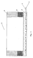
- a conventional micro-channel heat exchanger 20 generally comprises micro-channels or flat tubes 5, fins 4 disposed between the adjacent micro-channels or flat tubes 5, an inlet manifold 3 and an outlet manifold (not shown) disposed at ends of the micro-channels or flat tubes 5 respectively, and a refrigerant distributor 10 disposed in the inlet manifold 3 as shown in Figs. 1-2 .
- the refrigerant distributor 10 is disposed at a side of the heat exchanger 20 to distribute refrigerant.
- the distributor 10 may have a portion extending out of the inlet manifold 3 as shown in Fig. 1 or may have no portion extending out of the inlet manifold 3.
- the refrigerant distributor 10 comprises a pipe 9' in which a plurality of outlets 8 are formed in an axial direction of the pipe 9'.
- a refrigerant distributor 10 has been proposed as shown in Fig. 2 .
- the distributor 10 is formed by a cylindrical pipe in which a plurality of outlets 8 are formed through a wall of the cylindrical pipe. Assuming that refrigerant enters into the distributor 10 from an inlet 7 shown in Fig. 2 , the refrigerant flows along an inner chamber of the distributor, is ejected out of the pipe through the outlets 8, and then is mixed. After that, the mixed refrigerant flows into the flat tubes 5.
- the distributor is disadvantageous in that refrigerant is layered when it flows in the distributing pipe. The liquid refrigerant is located on a lower side and the gaseous refrigerant is located on an upper side due to the gravity.
- EP 1 798 507 A2 shows a heat exchanger, in particular an evaporator, having a refrigerant distributor.
- the refrigerant distributor comprises a pipe for distributing a refrigerant, for example R744, the pipe having a channel therein in which the refrigerant flows.
- the channel has at least one portion having a reduced cross-section area. This portion having reduced cross-section area is disposed between an end and another end of the pipe.
- JP 2004-278935 A shows another heat exchanger having a distributor.
- the distributor has a number of holes. Furthermore, a wall of the distributor has a number of protrusions and depressions.
- US 6 363 965 B1 shows a manifold assembly for use with a heating and cooling system having a body, said body having an open end and a closed end. Furthermore, the body has a plurality of connecting tube openings. Each tube opening is connected to a generally straight connecting tube. The connecting tube has different diameters along its length.
- the at least one portion having reduced cross-section area is a reducing segment formed by reducing a size of the pipe in a direction generally perpendicular to an axial direction of the pipe.
- the pipe may be a cylindrical pipe and the size is a diameter.
- the at least one portion having reduced cross-section area is a flat segment formed by pressing the portion of the pipe to be flat.
- the at least one portion having reduced cross-section area is a reducing segment formed by pressing an outer peripheral surface of the portion of the pipe.
- the at least one portion having reduced cross-section area is formed by a raised portion projecting inward from an inner wall of the pipe.
- the pipe has an inlet disposed at the end of the pipe and the refrigerant flows into the pipe through the inlet.
- the at least one portion having reduced cross-section area comprises a plurality of portions having reduced cross-section area. Distances between the adjacent portions having reduced cross-section area of the plurality of portions having reduced cross-section area gradually increase from the end to the other end of the pipe.
- At least one outlet is disposed between every two adjacent portions having reduced cross-section area of the plurality of portions having reduced cross-section area such that the refrigerant flows out of the pipe through the at least one outlet.
- the pipe has a plurality of outlets through which the refrigerant flows out of the pipe, the at least one portion having reduced cross-section area comprises a plurality of portions having reduced cross-section area, and a plurality of the portions having reduced cross-section area such as two portions having reduced cross-section area are disposed between every two adjacent outlets of the plurality of outlets.
- a heat exchanger comprising a refrigerant distributor disposed at a side of the heat exchanger to distribute refrigerant, wherein the refrigerant distributor is one of the distributors mentioned above.
- the heat exchanger may be a micro-channel heat exchanger.
- the refrigerant distributor alleviates the layering of refrigerant flowing in a distributing pipe and mixes the vapor-liquid refrigerant relatively uniformly.
- a micro-channel heat exchanger 2 according to the first embodiment of the present invention comprises micro-channels or flat tubes 5, fins 4 disposed between the adjacent micro-channels or flat tubes 5, an inlet manifold 3 and an outlet manifold (not shown) disposed at ends of the micro-channels or flat tubes 5 respectively, and a refrigerant distributor 1 disposed in the inlet manifold 3 as shown in Figs. 3-6 .
- the refrigerant distributor 1 is disposed at a side of the heat exchanger 2 to distribute refrigerant.
- the refrigerant distributor 1 for the heat exchanger comprises a pipe 9 for distributing refrigerant as shown in Figs. 3-6 .
- the pipe 9 has a channel 91 therein in which the refrigerant flows.
- the channel 91 has at least one portion having reduced cross-section area 6.
- the pipe 9 may be a cylindrical pipe.
- the pipe 9 further comprises a plurality of outlets 8 from which the refrigerant flows out of the pipe 9, and an inlet 7 through which the refrigerant flows into the pipe 9.
- At least one outlet 8 is disposed between every two adjacent portions having reduced cross-section area 6 of the plurality of portions having reduced cross-section area 6.
- one portion having reduced cross-section area 6, or a plurality of the portions having reduced cross-section area 6 such as two portions having reduced cross-section area are disposed between every two adjacent outlets 8 of the plurality of outlets 8.
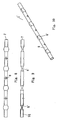
- the portions having reduced cross-section area 6 may be reducing segments 6 formed by reducing a size of the pipe 9 in a direction generally perpendicular to an axial direction of the pipe 9 as shown in Figs. 3-6 .
- the portions having reduced cross-section area 6 may be the reducing segments 6 formed by pressing an outer peripheral surface of the portions of the pipe 9.
- a diameter D2 of segments of a cylindrical pipe 9 positioned at intervals in a longitudinal direction of the cylindrical pipe 9 is reduced to a predetermined diameter D1 to form the reducing segments 6 as an example of the portions having reduced cross-section area, that is, D2 ⁇ D1.
- the outlets 8 are arranged through walls of the unreduced portions of the pipe 9.
- the refrigerant ejects every time it passes through one of the reducing segments 6.
- the vapor-liquid refrigerant is mixed uniformly.
- a part of the mixed refrigerant is ejected out of the pipe 9 through the outlets 8 in the unreduced portions of the pipe 9, and the remaining refrigerant continues advancing and is ejected again when flowing through the next reducing segment.
- the refrigerant is ejected multiple times through the reducing segments to be mixed more uniformly.
- two or more portions having reduced cross-section area 6 may be disposed between every two adjacent outlets 8 to eject the vapor-liquid fluid multiple times such that the vapor-liquid fluid is mixed uniformly when it flows out of the pipe through the outlets 8.
- distances between the adjacent portions having reduced cross-section area gradually increase from one end of the pipe, at which the inlet 7 is disposed, to the other end of the pipe.
- a refrigerant passes through the reducing segments 6 in a refrigerant flow direction R in which the refrigerant flows in the pipe 9, pressure loss occurs.
- the distances d1, d2, and d3 between the adjacent reducing segments are given as d3 ⁇ d2 ⁇ d1.
- the distances become larger in the refrigerant flow direction, thereby reducing large pressure loss that is caused by excessive reducing segments through which the refrigerant passes due to excessive length of a distributor.
- a number of the reducing segments is not limited and may be determined according to actual conditions.
- Openings with a predetermined size as the outlets 8 are formed by punching at intervals through a wall of a common smooth cylindrical pipe. Then, reducing segments 6 are formed by pressing an outer peripheral surface of the cylindrical pipe at predetermined positions between the adjacent openings in such a way that a size of a cross-section of the pipe located at the predetermined positions is reduced to a required size.
- a number of the opening as the outlet 8 in each of the unreduced portions between the adjacent reducing segments 6 is not limited to one, but two or more openings as the outlets 8 may be disposed in each of the unreduced portions between the adjacent reducing segments 6.
- the specific positions of the openings may be any appropriate positions and are dependent upon specific conditions.
- the pipe may be a pipe such as a pipe having an elliptical cross-section, a flat pipe and the like instead of the cylindrical pipe.
- a cross-section shape of the pipe is not limited.
- the pipe may have any appropriate cross-section shape.
- the pipe is not limited to a straight pipe, but may be a pipe having any appropriate shape.
- the cylindrical pipe 9 shown in Figs. 4-6 does not contain the portion extending out of the heat exchanger 2 as shown in Fig. 3 .
- a heat exchanger 2' according to the second embodiment of the present invention is the same as that of the first embodiment except a refrigerant distributor 1'. Only the distributor 1' is described below in detail.
- the refrigerant distributor 1' comprises a cylindrical pipe 9 as shown in Figs. 7-10 .
- the pipe 9 comprises a plurality of outlets 8 through which the refrigerant flows out of the pipe 9.
- the distributor 1' according to the second embodiment is the same as the distributor 1 according to the first embodiment except that the flat segments 6' as an example of the portions having reduced cross-section area according to the second embodiment is different from the reducing segments 6 of the first embodiment.
- the portions having reduced cross-section area 6' are flat segments 6' formed by pressing the portions of the pipe to be flat.
- the flat segments 6' facilitate manufacturing of the distributor and may be formed in a flat duckbill shape as shown in Figs. 7-10 .
- the cylindrical pipe 9 shown in Figs. 8-10 does not contain the portion extending out of the heat exchanger 2' as shown in Fig. 7 .
- the distributor according to the present invention can be applied to any other appropriate heat exchangers except of the micro-channel heat exchanger.
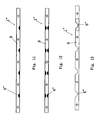
- distributors 1" may be configured as shown in Figs. 11-13 , and the portions having reduced cross-section area of the distributors 1" may be formed by raised portions 6" projecting inward from an inner wall of the pipe 9 as shown in Figs. 11-13 .
- Each raised portion 6" may be formed at a complete inner perimeter of the inner wall of the pipe or at a part of the inner perimeter.
- a wall of a pipe partially projects inward at a part of an outer perimeter of the pipe instead of the wall of the pipe projecting inward at the complete outer perimeter of the pipe.
- the portions having reduced cross-section area according to the present invention may be formed in other manners to generate turbulent flow of refrigerant or to eject refrigerant.
- At least one portion having reduced cross-section area is located between both ends of the pipe.
- the portion having reduced cross-section area may be positioned at the end of the pipe where the inlet 7 is disposed, such that refrigerant supplied to the distributor through a piping can be mixed uniformly.
- the portion having reduced cross-section area is described for ejecting refrigerant.
- the portion having reduced cross-section area may be used to generate turbulent flow of refrigerant instead of ejection of refrigerant, or to mix refrigerant.
- outlets 8 are disposed towards a direction perpendicular to the flat tubes 5 only for the purpose of illustration. However, the outlets 8 may be disposed towards any appropriate direction relative to the flat tubes 5.
Landscapes
- Engineering & Computer Science (AREA)
- Physics & Mathematics (AREA)
- Thermal Sciences (AREA)
- Mechanical Engineering (AREA)
- General Engineering & Computer Science (AREA)
- Heat-Exchange Devices With Radiators And Conduit Assemblies (AREA)
- Details Of Heat-Exchange And Heat-Transfer (AREA)
Claims (11)
- Kühlmittelverteiler für einen Wärmetauscher (2), umfassend:ein Rohr (9) zum Verteilen eines Kühlmittels, wobei das Rohr (9) darin einen Kanal (91) hat, durch den das Kühlmittel strömt,wobei der Kanal (91) mindestens einen Abschnitt (6, 6') mit reduzierter Querschnittsfläche hat, und wobei sich der mindestens eine Abschnitt (6, 6') mit reduzierter Querschnittsfläche zwischen einem Ende und einem anderen Ende des Rohrs befindet, wobei das Rohr (9) einen am Ende des Rohrs (9) befindlichen Einlass (7) hat, wobei das Kühlmittel durch den Einlass (7) hinein in das Rohr (9) strömt, und wobei der mindestens eine Abschnitt (6, 6', 6") mit reduzierter Querschnittsfläche mehrere Abschnitte mit reduzierter Querschnittsfläche umfasst, dadurch gekennzeichnet, dass Distanzen (d1, d2, d3) zwischen angrenzenden Abschnitten (6, 6', 6") mit reduzierter Querschnittsfläche der mehreren Abschnitte mit reduzierter Querschnittsfläche vom Ende zum anderen Ende des Rohrs (9) allmählich zunehmen.
- Kühlmittelverteiler für einen Wärmetauscher nach Anspruch 1, dadurch gekennzeichnet, dass der mindestens eine Abschnitt (6, 6', 6") mit reduzierter Querschnittsfläche ein reduzierendes Segment ist, das durch Reduzieren einer Größe des Rohrs (9) in einer allgemein senkrecht zu einer axialen Richtung des Rohrs (9) verlaufenden Richtung gebildet ist.
- Kühlmittelverteiler für einen Wärmetauscher nach Anspruch 1, dadurch gekennzeichnet, dass das Rohr (9) ein zylindrisches Rohr und die Größe ein Durchmesser ist.
- Kühlmittelverteiler für einen Wärmetauscher nach Anspruch 1, dadurch gekennzeichnet, dass der mindestens eine Abschnitt mit reduzierter Querschnittsfläche ein flaches Segment (6') ist, das durch Flachpressen des Abschnitts des Rohrs (9) gebildet ist.
- Kühlmittelverteiler für einen Wärmetauscher nach Anspruch 1, dadurch gekennzeichnet, dass der mindestens eine Abschnitt mit reduzierter Querschnittsfläche ein reduzierendes Segment (6") ist, das durch Pressen einer äußeren Umfangsfläche des Abschnitts des Rohrs gebildet ist.
- Kühlmittelverteiler für einen Wärmetauscher nach Anspruch 1, dadurch gekennzeichnet, dass der mindestens eine Abschnitt mit reduzierter Querschnittsfläche durch einen angehobenen Abschnitt (6") gebildet ist, der von einer inneren Wand des Rohrs aus nach innen vorspringt.
- Kühlmittelverteiler für einen Wärmetauscher nach Anspruch 1, dadurch gekennzeichnet, dass sich der mindestens eine Auslass (8) zwischen jeweils zwei angrenzenden Abschnitten (6, 6', 6") mit reduzierter Querschnittsfläche der mehreren Abschnitte mit reduzierter Querschnittsfläche befindet, so dass das Kühlmittel aus dem Rohr heraus durch den mindestens einen Auslass (8) strömt.
- Kühlmittelverteiler für einen Wärmetauscher nach Anspruch 1, dadurch gekennzeichnet, dass das Rohr (9) mehrere Auslässe (8) hat, durch die das Kühlmittel aus dem Rohr ausströmt, wobei sich mehrere der Abschnitte mit reduzierter Querschnittsfläche zwischen jeweils zwei angrenzenden Auslässen (8) der mehreren Auslässe befinden.
- Kühlmittelverteiler für einen Wärmetauscher nach Anspruch 1, dadurch gekennzeichnet, dass das Rohr (9) mehrere Auslässe (8) hat, durch die das Kühlmittel aus dem Rohr ausströmt, wobei sich zwei Abschnitte mit reduzierter Querschnittsfläche zwischen jeweils zwei angrenzenden Auslässen (8) der mehreren Auslässe befinden.
- Wärmetauscher (2), umfassend:einen Kühlmittelverteiler (1), der sich an einer Seite des Wärmetauschers (2) befindet, um Kühlmittel zu verteilen,wobei es sich bei dem Kühlmittelverteiler (1) um den Kühlmittelverteiler (1) nach einem der Ansprüche 1 bis 9 handelt.
- Wärmetauscher nach Anspruch 10, wobei es sich bei dem Wärmetauscher (2) um einen Mikrokanalwärmetauscher handelt.
Applications Claiming Priority (1)
| Application Number | Priority Date | Filing Date | Title |
|---|---|---|---|
| CN2009101320097A CN101788243B (zh) | 2009-04-03 | 2009-04-03 | 用于热交换器的制冷剂分配器和热交换器 |
Publications (3)
| Publication Number | Publication Date |
|---|---|
| EP2241852A2 EP2241852A2 (de) | 2010-10-20 |
| EP2241852A3 EP2241852A3 (de) | 2014-01-15 |
| EP2241852B1 true EP2241852B1 (de) | 2015-06-10 |
Family
ID=42263908
Family Applications (1)
| Application Number | Title | Priority Date | Filing Date |
|---|---|---|---|
| EP10003238.2A Not-in-force EP2241852B1 (de) | 2009-04-03 | 2010-03-26 | Kühlmittelverteiler für Wärmetauscher und Wärmetauscher |
Country Status (3)
| Country | Link |
|---|---|
| US (1) | US9423190B2 (de) |
| EP (1) | EP2241852B1 (de) |
| CN (1) | CN101788243B (de) |
Families Citing this family (19)
| Publication number | Priority date | Publication date | Assignee | Title |
|---|---|---|---|---|
| CN101788242A (zh) * | 2009-03-25 | 2010-07-28 | 三花丹佛斯(杭州)微通道换热器有限公司 | 用于热交换器的制冷剂分配器和热交换器 |
| CN101922882B (zh) * | 2010-09-13 | 2011-12-28 | 三花丹佛斯(杭州)微通道换热器有限公司 | 制冷剂导管和具有该制冷剂导管的换热器 |
| CN102079038B (zh) | 2010-12-08 | 2013-02-13 | 三花控股集团有限公司 | 一种换热器及其制冷剂导流管,以及制冷剂导流管的加工方法 |
| DE102012205771A1 (de) * | 2012-04-10 | 2013-10-10 | Siemens Aktiengesellschaft | Wärmespeicher für Kraftwerksleistungen |
| EP2674715A1 (de) * | 2012-06-14 | 2013-12-18 | Alfa Laval Corporate AB | Plattenwärmetauscher mit Fliessbohrung |
| CN103411463A (zh) * | 2013-08-27 | 2013-11-27 | 杭州三花微通道换热器有限公司 | 制冷剂分配部件、集流管组件和换热器 |
| CN107850396A (zh) * | 2015-06-29 | 2018-03-27 | 开利公司 | 两相分配器蒸发器 |
| CN107543336A (zh) * | 2016-06-23 | 2018-01-05 | 杭州三花家电热管理系统有限公司 | 集流管和具有该集流管的换热器 |
| WO2018055826A1 (ja) * | 2016-09-23 | 2018-03-29 | 東芝キヤリア株式会社 | 熱交換器及び冷凍サイクル装置 |
| EP4246075A3 (de) * | 2017-05-05 | 2023-12-06 | Carrier Corporation | Wärmetauscher für wärmepumpenanwendungen |
| FR3075348B1 (fr) * | 2017-12-19 | 2020-05-15 | Valeo Systemes Thermiques | Dispositif de distribution d'un fluide refrigerant destine a etre loge dans une boite collectrice d'un echangeur de chaleur |
| JP6576577B1 (ja) * | 2018-06-11 | 2019-09-18 | 三菱電機株式会社 | 冷媒分配器、熱交換器及び空気調和装置 |
| US10982870B2 (en) * | 2018-08-31 | 2021-04-20 | Jonhson Controls Technology Company | Working fluid distribution systems |
| CN110940220B (zh) * | 2018-09-25 | 2022-03-01 | 丹佛斯有限公司 | 用于换热器的分配管组件和具有该分配管组件的集流管组件和换热器 |
| CN111288833B (zh) * | 2018-12-06 | 2022-03-15 | 丹佛斯有限公司 | 集流管组件以及换热器 |
| CN112815752B (zh) * | 2020-12-31 | 2022-09-20 | 北京航空航天大学 | 一种航天器两相流体换热回路热控系统 |
| CN116817628A (zh) * | 2022-04-22 | 2023-09-29 | 浙江三花智能控制股份有限公司 | 换热器 |
| WO2024084543A1 (ja) * | 2022-10-17 | 2024-04-25 | 三菱電機株式会社 | 冷凍サイクル装置、熱交換器および冷媒分配器 |
| US12566035B2 (en) * | 2022-12-23 | 2026-03-03 | Carrier Corporation | Simple distributor for inlet manifold of microchannel heat exchanger |
Family Cites Families (29)
| Publication number | Priority date | Publication date | Assignee | Title |
|---|---|---|---|---|
| US1315853A (en) * | 1919-09-09 | Kabii bvaiid nokduitg and bttben bagnab | ||
| US1662236A (en) * | 1926-09-11 | 1928-03-13 | Edmund Mcgillivray | Steam and hot-water radiator |
| US2252045A (en) * | 1938-10-18 | 1941-08-12 | Spanner Edward Frank | Tubular heat exchange apparatus |
| US2942858A (en) * | 1958-04-21 | 1960-06-28 | American Air Filter Co | Heat exchange apparatus |
| US3026092A (en) * | 1958-08-18 | 1962-03-20 | Marlo Coil Company | Heat exchanger |
| US3232341A (en) * | 1960-02-01 | 1966-02-01 | Garrett Corp | Condenser |
| US3826304A (en) * | 1967-10-11 | 1974-07-30 | Universal Oil Prod Co | Advantageous configuration of tubing for internal boiling |
| US3976128A (en) * | 1975-06-12 | 1976-08-24 | Ford Motor Company | Plate and fin heat exchanger |
| US5806586A (en) * | 1993-07-03 | 1998-09-15 | Ernst Flitsch Gmbh & Co. | Plate heat exchanger with a refrigerant distributor |
| JP3216960B2 (ja) * | 1994-09-19 | 2001-10-09 | 株式会社日立製作所 | 空気調和機の室外機、室内機及びそれらに用いられる冷媒分配器 |
| AU5784699A (en) * | 1998-08-25 | 2000-03-14 | Aeroquip Corporation | Manifold assembly |
| CA2289428C (en) * | 1998-12-04 | 2008-12-09 | Beckett Gas, Inc. | Heat exchanger tube with integral restricting and turbulating structure |
| DE10100241A1 (de) * | 2001-01-05 | 2002-07-18 | Hde Metallwerk Gmbh | Wärmetauscherrohr für flüssige oder gasförmige Medien |
| US6729386B1 (en) * | 2001-01-22 | 2004-05-04 | Stanley H. Sather | Pulp drier coil with improved header |
| US7017656B2 (en) * | 2001-05-24 | 2006-03-28 | Honeywell International, Inc. | Heat exchanger with manifold tubes for stiffening and load bearing |
| JP2004278935A (ja) * | 2003-03-17 | 2004-10-07 | Calsonic Kansei Corp | 蒸発器 |
| EP1548380A3 (de) * | 2003-12-22 | 2006-10-04 | Hussmann Corporation | Flachrohrverdampfer mit Mikroverteiler |
| US7086249B2 (en) * | 2004-10-01 | 2006-08-08 | Advanced Heat Transfer, Llc | Refrigerant distribution device and method |
| US7398819B2 (en) * | 2004-11-12 | 2008-07-15 | Carrier Corporation | Minichannel heat exchanger with restrictive inserts |
| TWM267829U (en) * | 2004-11-24 | 2005-06-11 | Forward Electronics Co Ltd | Liquid cooling pipe having internal separation plate in liquid-cooling type heat sink |
| US8113270B2 (en) * | 2005-02-02 | 2012-02-14 | Carrier Corporation | Tube insert and bi-flow arrangement for a header of a heat pump |
| US7275394B2 (en) * | 2005-04-22 | 2007-10-02 | Visteon Global Technologies, Inc. | Heat exchanger having a distributer plate |
| EP1798507A2 (de) * | 2005-12-13 | 2007-06-20 | Behr GmbH & Co. KG | Wärmetauscher, insbesondere Verdampfer |
| DE102006016839B4 (de) * | 2006-04-07 | 2025-10-30 | Att Automotivethermotech Gmbh | Öl-Kühlmittel-Wärmetauscher für Kraftfahrzeuge |
| EA014861B1 (ru) * | 2006-05-30 | 2011-02-28 | Необульб Текнолоджиз Инк. | Светодиодное осветительное оборудование высокой мощности с высокой эффективностью теплоотвода |
| CN200949725Y (zh) * | 2006-06-10 | 2007-09-19 | 戴丁军 | 流体分配器 |
| US20080013278A1 (en) * | 2006-06-30 | 2008-01-17 | Fredric Landry | Reservoir for liquid cooling systems used to provide make-up fluid and trap gas bubbles |
| EP2082181B1 (de) * | 2006-11-13 | 2014-06-11 | Carrier Corporation | Parallelstromwärmetauscher |
| US8151907B2 (en) * | 2008-04-18 | 2012-04-10 | Shell Oil Company | Dual motor systems and non-rotating sensors for use in developing wellbores in subsurface formations |
-
2009
- 2009-04-03 CN CN2009101320097A patent/CN101788243B/zh not_active Expired - Fee Related
-
2010
- 2010-03-26 EP EP10003238.2A patent/EP2241852B1/de not_active Not-in-force
- 2010-03-31 US US12/751,311 patent/US9423190B2/en not_active Expired - Fee Related
Also Published As
| Publication number | Publication date |
|---|---|
| CN101788243A (zh) | 2010-07-28 |
| US20100252243A1 (en) | 2010-10-07 |
| CN101788243B (zh) | 2011-09-28 |
| US9423190B2 (en) | 2016-08-23 |
| EP2241852A2 (de) | 2010-10-20 |
| EP2241852A3 (de) | 2014-01-15 |
Similar Documents
| Publication | Publication Date | Title |
|---|---|---|
| EP2241852B1 (de) | Kühlmittelverteiler für Wärmetauscher und Wärmetauscher | |
| EP2236973B1 (de) | Kühlmittelverteiler für Wärmetauscher und Wärmetauscher | |
| EP1884733B1 (de) | Wärmetauscheranordnung mit unterteilten Sammelrohren | |
| US9528778B2 (en) | Refrigerant guiding pipe and heat exchanger having refrigerant guiding pipe | |
| KR100908769B1 (ko) | 병류 열교환기와, 균일한 냉매 유동을 촉진하는 방법 | |
| US8485248B2 (en) | Flow distributor for a heat exchanger assembly | |
| EP2278246B1 (de) | Verteilerrohr mit gleichmäßiger Kühlflüssigkeitsverteilung | |
| EP3033579B1 (de) | Wärmetauscher und strömungsverteiler | |
| KR20110110722A (ko) | 입구 분배기 및 출구 수집기를 구비한 향상된 열교환기 | |
| CN104154801B (zh) | 集流管和换热器 | |
| US11592244B2 (en) | Multiport fluid distributor and microchannel heat exchanger having the same | |
| EP3314191B1 (de) | Verdampfer mit zweiphasigem verteiler | |
| WO2008060270A1 (en) | Minichannel heat exchanger header insert for distribution | |
| JP2007078298A (ja) | 熱交換器 | |
| CN102954627B (zh) | 换热器 | |
| EP2724107B1 (de) | Mantel und röhrenwärmetauscher mit mikrokanäle | |
| CN101886891B (zh) | 制冷剂导引装置和具有它的换热器 | |
| US20250283673A1 (en) | Laminated header for a microchannel heat exchanger | |
| CN209877733U (zh) | 气液分配器及其换热器 | |
| US20250137738A1 (en) | Microchannel heat exchanger | |
| US20250369708A1 (en) | Fluid distributor for microchannel heat exchanger | |
| CN118548744A (zh) | 一种分配管及具有该分配管的换热器 | |
| CN109780763B (zh) | 一种两用式分配器 | |
| CN118475809A (zh) | 热交换器以及制造热交换器的方法 | |
| HK1138637B (en) | Minichannel heat exchanger header insert for distribution |
Legal Events
| Date | Code | Title | Description |
|---|---|---|---|
| PUAI | Public reference made under article 153(3) epc to a published international application that has entered the european phase |
Free format text: ORIGINAL CODE: 0009012 |
|
| AK | Designated contracting states |
Kind code of ref document: A2 Designated state(s): AT BE BG CH CY CZ DE DK EE ES FI FR GB GR HR HU IE IS IT LI LT LU LV MC MK MT NL NO PL PT RO SE SI SK SM TR |
|
| AX | Request for extension of the european patent |
Extension state: AL BA ME RS |
|
| RAP1 | Party data changed (applicant data changed or rights of an application transferred) |
Owner name: SANHUA HOLDING GROUP CO., LTD. Owner name: DANFOSS A/S |
|
| PUAL | Search report despatched |
Free format text: ORIGINAL CODE: 0009013 |
|
| AK | Designated contracting states |
Kind code of ref document: A3 Designated state(s): AT BE BG CH CY CZ DE DK EE ES FI FR GB GR HR HU IE IS IT LI LT LU LV MC MK MT NL NO PL PT RO SE SI SK SM TR |
|
| AX | Request for extension of the european patent |
Extension state: AL BA ME RS |
|
| RIC1 | Information provided on ipc code assigned before grant |
Ipc: F28F 9/02 20060101AFI20131206BHEP Ipc: F25B 39/02 20060101ALI20131206BHEP |
|
| RBV | Designated contracting states (corrected) |
Designated state(s): AT BE BG CH CY CZ DE DK EE ES FI FR GB GR HR HU IE IS IT LI LT LU LV MC MK MT NL NO PL PT RO SE SI SK SM TR |
|
| 17P | Request for examination filed |
Effective date: 20140710 |
|
| GRAP | Despatch of communication of intention to grant a patent |
Free format text: ORIGINAL CODE: EPIDOSNIGR1 |
|
| INTG | Intention to grant announced |
Effective date: 20150220 |
|
| GRAS | Grant fee paid |
Free format text: ORIGINAL CODE: EPIDOSNIGR3 |
|
| RAP1 | Party data changed (applicant data changed or rights of an application transferred) |
Owner name: SANHUA (HANGZHOU) MICRO CHANNEL HEAT EXCHANGER CO. Owner name: DANFOSS A/S |
|
| GRAA | (expected) grant |
Free format text: ORIGINAL CODE: 0009210 |
|
| AK | Designated contracting states |
Kind code of ref document: B1 Designated state(s): AT BE BG CH CY CZ DE DK EE ES FI FR GB GR HR HU IE IS IT LI LT LU LV MC MK MT NL NO PL PT RO SE SI SK SM TR |
|
| REG | Reference to a national code |
Ref country code: GB Ref legal event code: FG4D |
|
| REG | Reference to a national code |
Ref country code: CH Ref legal event code: EP |
|
| REG | Reference to a national code |
Ref country code: AT Ref legal event code: REF Ref document number: 731091 Country of ref document: AT Kind code of ref document: T Effective date: 20150715 |
|
| REG | Reference to a national code |
Ref country code: DE Ref legal event code: R096 Ref document number: 602010025129 Country of ref document: DE |
|
| REG | Reference to a national code |
Ref country code: IE Ref legal event code: FG4D |
|
| REG | Reference to a national code |
Ref country code: DE Ref legal event code: R082 Ref document number: 602010025129 Country of ref document: DE Representative=s name: PATENTANWAELTE DR. KNOBLAUCH PARTGMBB, DE |
|
| PG25 | Lapsed in a contracting state [announced via postgrant information from national office to epo] |
Ref country code: LT Free format text: LAPSE BECAUSE OF FAILURE TO SUBMIT A TRANSLATION OF THE DESCRIPTION OR TO PAY THE FEE WITHIN THE PRESCRIBED TIME-LIMIT Effective date: 20150610 Ref country code: FI Free format text: LAPSE BECAUSE OF FAILURE TO SUBMIT A TRANSLATION OF THE DESCRIPTION OR TO PAY THE FEE WITHIN THE PRESCRIBED TIME-LIMIT Effective date: 20150610 Ref country code: ES Free format text: LAPSE BECAUSE OF FAILURE TO SUBMIT A TRANSLATION OF THE DESCRIPTION OR TO PAY THE FEE WITHIN THE PRESCRIBED TIME-LIMIT Effective date: 20150610 Ref country code: NO Free format text: LAPSE BECAUSE OF FAILURE TO SUBMIT A TRANSLATION OF THE DESCRIPTION OR TO PAY THE FEE WITHIN THE PRESCRIBED TIME-LIMIT Effective date: 20150910 |
|
| REG | Reference to a national code |
Ref country code: AT Ref legal event code: MK05 Ref document number: 731091 Country of ref document: AT Kind code of ref document: T Effective date: 20150610 |
|
| REG | Reference to a national code |
Ref country code: NL Ref legal event code: MP Effective date: 20150610 |
|
| PG25 | Lapsed in a contracting state [announced via postgrant information from national office to epo] |
Ref country code: BG Free format text: LAPSE BECAUSE OF FAILURE TO SUBMIT A TRANSLATION OF THE DESCRIPTION OR TO PAY THE FEE WITHIN THE PRESCRIBED TIME-LIMIT Effective date: 20150910 Ref country code: GR Free format text: LAPSE BECAUSE OF FAILURE TO SUBMIT A TRANSLATION OF THE DESCRIPTION OR TO PAY THE FEE WITHIN THE PRESCRIBED TIME-LIMIT Effective date: 20150911 Ref country code: LV Free format text: LAPSE BECAUSE OF FAILURE TO SUBMIT A TRANSLATION OF THE DESCRIPTION OR TO PAY THE FEE WITHIN THE PRESCRIBED TIME-LIMIT Effective date: 20150610 |
|
| PG25 | Lapsed in a contracting state [announced via postgrant information from national office to epo] |
Ref country code: EE Free format text: LAPSE BECAUSE OF FAILURE TO SUBMIT A TRANSLATION OF THE DESCRIPTION OR TO PAY THE FEE WITHIN THE PRESCRIBED TIME-LIMIT Effective date: 20150610 |
|
| PG25 | Lapsed in a contracting state [announced via postgrant information from national office to epo] |
Ref country code: RO Free format text: LAPSE BECAUSE OF NON-PAYMENT OF DUE FEES Effective date: 20150610 Ref country code: SK Free format text: LAPSE BECAUSE OF FAILURE TO SUBMIT A TRANSLATION OF THE DESCRIPTION OR TO PAY THE FEE WITHIN THE PRESCRIBED TIME-LIMIT Effective date: 20150610 Ref country code: PT Free format text: LAPSE BECAUSE OF FAILURE TO SUBMIT A TRANSLATION OF THE DESCRIPTION OR TO PAY THE FEE WITHIN THE PRESCRIBED TIME-LIMIT Effective date: 20151012 Ref country code: PL Free format text: LAPSE BECAUSE OF FAILURE TO SUBMIT A TRANSLATION OF THE DESCRIPTION OR TO PAY THE FEE WITHIN THE PRESCRIBED TIME-LIMIT Effective date: 20150610 Ref country code: AT Free format text: LAPSE BECAUSE OF FAILURE TO SUBMIT A TRANSLATION OF THE DESCRIPTION OR TO PAY THE FEE WITHIN THE PRESCRIBED TIME-LIMIT Effective date: 20150610 Ref country code: IS Free format text: LAPSE BECAUSE OF FAILURE TO SUBMIT A TRANSLATION OF THE DESCRIPTION OR TO PAY THE FEE WITHIN THE PRESCRIBED TIME-LIMIT Effective date: 20151010 Ref country code: CZ Free format text: LAPSE BECAUSE OF FAILURE TO SUBMIT A TRANSLATION OF THE DESCRIPTION OR TO PAY THE FEE WITHIN THE PRESCRIBED TIME-LIMIT Effective date: 20150610 |
|
| REG | Reference to a national code |
Ref country code: DE Ref legal event code: R097 Ref document number: 602010025129 Country of ref document: DE |
|
| REG | Reference to a national code |
Ref country code: FR Ref legal event code: PLFP Year of fee payment: 7 |
|
| PLBE | No opposition filed within time limit |
Free format text: ORIGINAL CODE: 0009261 |
|
| STAA | Information on the status of an ep patent application or granted ep patent |
Free format text: STATUS: NO OPPOSITION FILED WITHIN TIME LIMIT |
|
| PG25 | Lapsed in a contracting state [announced via postgrant information from national office to epo] |
Ref country code: DK Free format text: LAPSE BECAUSE OF FAILURE TO SUBMIT A TRANSLATION OF THE DESCRIPTION OR TO PAY THE FEE WITHIN THE PRESCRIBED TIME-LIMIT Effective date: 20150610 |
|
| 26N | No opposition filed |
Effective date: 20160311 |
|
| PG25 | Lapsed in a contracting state [announced via postgrant information from national office to epo] |
Ref country code: SI Free format text: LAPSE BECAUSE OF FAILURE TO SUBMIT A TRANSLATION OF THE DESCRIPTION OR TO PAY THE FEE WITHIN THE PRESCRIBED TIME-LIMIT Effective date: 20150610 |
|
| PG25 | Lapsed in a contracting state [announced via postgrant information from national office to epo] |
Ref country code: BE Free format text: LAPSE BECAUSE OF NON-PAYMENT OF DUE FEES Effective date: 20160331 |
|
| PG25 | Lapsed in a contracting state [announced via postgrant information from national office to epo] |
Ref country code: LU Free format text: LAPSE BECAUSE OF FAILURE TO SUBMIT A TRANSLATION OF THE DESCRIPTION OR TO PAY THE FEE WITHIN THE PRESCRIBED TIME-LIMIT Effective date: 20160326 Ref country code: MC Free format text: LAPSE BECAUSE OF FAILURE TO SUBMIT A TRANSLATION OF THE DESCRIPTION OR TO PAY THE FEE WITHIN THE PRESCRIBED TIME-LIMIT Effective date: 20150610 |
|
| REG | Reference to a national code |
Ref country code: CH Ref legal event code: PL |
|
| GBPC | Gb: european patent ceased through non-payment of renewal fee |
Effective date: 20160326 |
|
| REG | Reference to a national code |
Ref country code: IE Ref legal event code: MM4A |
|
| PG25 | Lapsed in a contracting state [announced via postgrant information from national office to epo] |
Ref country code: BE Free format text: LAPSE BECAUSE OF FAILURE TO SUBMIT A TRANSLATION OF THE DESCRIPTION OR TO PAY THE FEE WITHIN THE PRESCRIBED TIME-LIMIT Effective date: 20150610 |
|
| PG25 | Lapsed in a contracting state [announced via postgrant information from national office to epo] |
Ref country code: GB Free format text: LAPSE BECAUSE OF NON-PAYMENT OF DUE FEES Effective date: 20160326 Ref country code: LI Free format text: LAPSE BECAUSE OF NON-PAYMENT OF DUE FEES Effective date: 20160331 Ref country code: IE Free format text: LAPSE BECAUSE OF NON-PAYMENT OF DUE FEES Effective date: 20160326 Ref country code: CH Free format text: LAPSE BECAUSE OF NON-PAYMENT OF DUE FEES Effective date: 20160331 |
|
| REG | Reference to a national code |
Ref country code: FR Ref legal event code: PLFP Year of fee payment: 8 |
|
| PG25 | Lapsed in a contracting state [announced via postgrant information from national office to epo] |
Ref country code: NL Free format text: LAPSE BECAUSE OF FAILURE TO SUBMIT A TRANSLATION OF THE DESCRIPTION OR TO PAY THE FEE WITHIN THE PRESCRIBED TIME-LIMIT Effective date: 20150610 Ref country code: SE Free format text: LAPSE BECAUSE OF FAILURE TO SUBMIT A TRANSLATION OF THE DESCRIPTION OR TO PAY THE FEE WITHIN THE PRESCRIBED TIME-LIMIT Effective date: 20150610 |
|
| PG25 | Lapsed in a contracting state [announced via postgrant information from national office to epo] |
Ref country code: MT Free format text: LAPSE BECAUSE OF FAILURE TO SUBMIT A TRANSLATION OF THE DESCRIPTION OR TO PAY THE FEE WITHIN THE PRESCRIBED TIME-LIMIT Effective date: 20150610 |
|
| REG | Reference to a national code |
Ref country code: FR Ref legal event code: PLFP Year of fee payment: 9 |
|
| PG25 | Lapsed in a contracting state [announced via postgrant information from national office to epo] |
Ref country code: HU Free format text: LAPSE BECAUSE OF FAILURE TO SUBMIT A TRANSLATION OF THE DESCRIPTION OR TO PAY THE FEE WITHIN THE PRESCRIBED TIME-LIMIT; INVALID AB INITIO Effective date: 20100326 Ref country code: SM Free format text: LAPSE BECAUSE OF FAILURE TO SUBMIT A TRANSLATION OF THE DESCRIPTION OR TO PAY THE FEE WITHIN THE PRESCRIBED TIME-LIMIT Effective date: 20150610 Ref country code: CY Free format text: LAPSE BECAUSE OF FAILURE TO SUBMIT A TRANSLATION OF THE DESCRIPTION OR TO PAY THE FEE WITHIN THE PRESCRIBED TIME-LIMIT Effective date: 20150610 |
|
| PG25 | Lapsed in a contracting state [announced via postgrant information from national office to epo] |
Ref country code: HR Free format text: LAPSE BECAUSE OF FAILURE TO SUBMIT A TRANSLATION OF THE DESCRIPTION OR TO PAY THE FEE WITHIN THE PRESCRIBED TIME-LIMIT Effective date: 20150610 Ref country code: MK Free format text: LAPSE BECAUSE OF FAILURE TO SUBMIT A TRANSLATION OF THE DESCRIPTION OR TO PAY THE FEE WITHIN THE PRESCRIBED TIME-LIMIT Effective date: 20150610 Ref country code: MT Free format text: LAPSE BECAUSE OF FAILURE TO SUBMIT A TRANSLATION OF THE DESCRIPTION OR TO PAY THE FEE WITHIN THE PRESCRIBED TIME-LIMIT Effective date: 20160331 Ref country code: TR Free format text: LAPSE BECAUSE OF FAILURE TO SUBMIT A TRANSLATION OF THE DESCRIPTION OR TO PAY THE FEE WITHIN THE PRESCRIBED TIME-LIMIT Effective date: 20150610 |
|
| REG | Reference to a national code |
Ref country code: DE Ref legal event code: R082 Ref document number: 602010025129 Country of ref document: DE Representative=s name: KEIL & SCHAAFHAUSEN PATENTANWAELTE PARTGMBB, DE Ref country code: DE Ref legal event code: R082 Ref document number: 602010025129 Country of ref document: DE Representative=s name: KEIL & SCHAAFHAUSEN PATENT- UND RECHTSANWAELTE, DE |
|
| PGFP | Annual fee paid to national office [announced via postgrant information from national office to epo] |
Ref country code: DE Payment date: 20220331 Year of fee payment: 13 |
|
| PGFP | Annual fee paid to national office [announced via postgrant information from national office to epo] |
Ref country code: FR Payment date: 20220309 Year of fee payment: 13 |
|
| PGFP | Annual fee paid to national office [announced via postgrant information from national office to epo] |
Ref country code: IT Payment date: 20220330 Year of fee payment: 13 |
|
| REG | Reference to a national code |
Ref country code: DE Ref legal event code: R119 Ref document number: 602010025129 Country of ref document: DE |
|
| PG25 | Lapsed in a contracting state [announced via postgrant information from national office to epo] |
Ref country code: FR Free format text: LAPSE BECAUSE OF NON-PAYMENT OF DUE FEES Effective date: 20230331 Ref country code: DE Free format text: LAPSE BECAUSE OF NON-PAYMENT OF DUE FEES Effective date: 20231003 |
|
| PG25 | Lapsed in a contracting state [announced via postgrant information from national office to epo] |
Ref country code: IT Free format text: LAPSE BECAUSE OF NON-PAYMENT OF DUE FEES Effective date: 20230326 |