EP2278246B1 - Verteilerrohr mit gleichmäßiger Kühlflüssigkeitsverteilung - Google Patents
Verteilerrohr mit gleichmäßiger Kühlflüssigkeitsverteilung Download PDFInfo
- Publication number
- EP2278246B1 EP2278246B1 EP09013700.1A EP09013700A EP2278246B1 EP 2278246 B1 EP2278246 B1 EP 2278246B1 EP 09013700 A EP09013700 A EP 09013700A EP 2278246 B1 EP2278246 B1 EP 2278246B1
- Authority
- EP
- European Patent Office
- Prior art keywords
- manifold
- distributor tube
- openings
- refrigerant
- heat exchanger
- Prior art date
- Legal status (The legal status is an assumption and is not a legal conclusion. Google has not performed a legal analysis and makes no representation as to the accuracy of the status listed.)
- Active
Links
Images


Classifications
-
- F—MECHANICAL ENGINEERING; LIGHTING; HEATING; WEAPONS; BLASTING
- F28—HEAT EXCHANGE IN GENERAL
- F28F—DETAILS OF HEAT-EXCHANGE AND HEAT-TRANSFER APPARATUS, OF GENERAL APPLICATION
- F28F9/00—Casings; Header boxes; Auxiliary supports for elements; Auxiliary members within casings
- F28F9/02—Header boxes; End plates
- F28F9/026—Header boxes; End plates with static flow control means, e.g. with means for uniformly distributing heat exchange media into conduits
- F28F9/027—Header boxes; End plates with static flow control means, e.g. with means for uniformly distributing heat exchange media into conduits in the form of distribution pipes
- F28F9/0273—Header boxes; End plates with static flow control means, e.g. with means for uniformly distributing heat exchange media into conduits in the form of distribution pipes with multiple holes
-
- F—MECHANICAL ENGINEERING; LIGHTING; HEATING; WEAPONS; BLASTING
- F28—HEAT EXCHANGE IN GENERAL
- F28F—DETAILS OF HEAT-EXCHANGE AND HEAT-TRANSFER APPARATUS, OF GENERAL APPLICATION
- F28F9/00—Casings; Header boxes; Auxiliary supports for elements; Auxiliary members within casings
- F28F9/02—Header boxes; End plates
-
- F—MECHANICAL ENGINEERING; LIGHTING; HEATING; WEAPONS; BLASTING
- F25—REFRIGERATION OR COOLING; COMBINED HEATING AND REFRIGERATION SYSTEMS; HEAT PUMP SYSTEMS; MANUFACTURE OR STORAGE OF ICE; LIQUEFACTION SOLIDIFICATION OF GASES
- F25B—REFRIGERATION MACHINES, PLANTS OR SYSTEMS; COMBINED HEATING AND REFRIGERATION SYSTEMS; HEAT PUMP SYSTEMS
- F25B39/00—Evaporators; Condensers
- F25B39/02—Evaporators
- F25B39/028—Evaporators having distributing means
-
- F—MECHANICAL ENGINEERING; LIGHTING; HEATING; WEAPONS; BLASTING
- F28—HEAT EXCHANGE IN GENERAL
- F28D—HEAT-EXCHANGE APPARATUS, NOT PROVIDED FOR IN ANOTHER SUBCLASS, IN WHICH THE HEAT-EXCHANGE MEDIA DO NOT COME INTO DIRECT CONTACT
- F28D1/00—Heat-exchange apparatus having stationary conduit assemblies for one heat-exchange medium only, the media being in contact with different sides of the conduit wall, in which the other heat-exchange medium is a large body of fluid, e.g. domestic or motor car radiators
- F28D1/02—Heat-exchange apparatus having stationary conduit assemblies for one heat-exchange medium only, the media being in contact with different sides of the conduit wall, in which the other heat-exchange medium is a large body of fluid, e.g. domestic or motor car radiators with heat-exchange conduits immersed in the body of fluid
- F28D1/04—Heat-exchange apparatus having stationary conduit assemblies for one heat-exchange medium only, the media being in contact with different sides of the conduit wall, in which the other heat-exchange medium is a large body of fluid, e.g. domestic or motor car radiators with heat-exchange conduits immersed in the body of fluid with tubular conduits
- F28D1/053—Heat-exchange apparatus having stationary conduit assemblies for one heat-exchange medium only, the media being in contact with different sides of the conduit wall, in which the other heat-exchange medium is a large body of fluid, e.g. domestic or motor car radiators with heat-exchange conduits immersed in the body of fluid with tubular conduits the conduits being straight
- F28D1/05316—Assemblies of conduits connected to common headers, e.g. core type radiators
-
- F—MECHANICAL ENGINEERING; LIGHTING; HEATING; WEAPONS; BLASTING
- F28—HEAT EXCHANGE IN GENERAL
- F28D—HEAT-EXCHANGE APPARATUS, NOT PROVIDED FOR IN ANOTHER SUBCLASS, IN WHICH THE HEAT-EXCHANGE MEDIA DO NOT COME INTO DIRECT CONTACT
- F28D1/00—Heat-exchange apparatus having stationary conduit assemblies for one heat-exchange medium only, the media being in contact with different sides of the conduit wall, in which the other heat-exchange medium is a large body of fluid, e.g. domestic or motor car radiators
- F28D1/02—Heat-exchange apparatus having stationary conduit assemblies for one heat-exchange medium only, the media being in contact with different sides of the conduit wall, in which the other heat-exchange medium is a large body of fluid, e.g. domestic or motor car radiators with heat-exchange conduits immersed in the body of fluid
- F28D1/04—Heat-exchange apparatus having stationary conduit assemblies for one heat-exchange medium only, the media being in contact with different sides of the conduit wall, in which the other heat-exchange medium is a large body of fluid, e.g. domestic or motor car radiators with heat-exchange conduits immersed in the body of fluid with tubular conduits
- F28D1/053—Heat-exchange apparatus having stationary conduit assemblies for one heat-exchange medium only, the media being in contact with different sides of the conduit wall, in which the other heat-exchange medium is a large body of fluid, e.g. domestic or motor car radiators with heat-exchange conduits immersed in the body of fluid with tubular conduits the conduits being straight
- F28D1/0535—Heat-exchange apparatus having stationary conduit assemblies for one heat-exchange medium only, the media being in contact with different sides of the conduit wall, in which the other heat-exchange medium is a large body of fluid, e.g. domestic or motor car radiators with heat-exchange conduits immersed in the body of fluid with tubular conduits the conduits being straight the conduits having a non-circular cross-section
- F28D1/05366—Assemblies of conduits connected to common headers, e.g. core type radiators
- F28D1/05383—Assemblies of conduits connected to common headers, e.g. core type radiators with multiple rows of conduits or with multi-channel conduits
-
- F—MECHANICAL ENGINEERING; LIGHTING; HEATING; WEAPONS; BLASTING
- F28—HEAT EXCHANGE IN GENERAL
- F28D—HEAT-EXCHANGE APPARATUS, NOT PROVIDED FOR IN ANOTHER SUBCLASS, IN WHICH THE HEAT-EXCHANGE MEDIA DO NOT COME INTO DIRECT CONTACT
- F28D1/00—Heat-exchange apparatus having stationary conduit assemblies for one heat-exchange medium only, the media being in contact with different sides of the conduit wall, in which the other heat-exchange medium is a large body of fluid, e.g. domestic or motor car radiators
- F28D1/02—Heat-exchange apparatus having stationary conduit assemblies for one heat-exchange medium only, the media being in contact with different sides of the conduit wall, in which the other heat-exchange medium is a large body of fluid, e.g. domestic or motor car radiators with heat-exchange conduits immersed in the body of fluid
- F28D1/04—Heat-exchange apparatus having stationary conduit assemblies for one heat-exchange medium only, the media being in contact with different sides of the conduit wall, in which the other heat-exchange medium is a large body of fluid, e.g. domestic or motor car radiators with heat-exchange conduits immersed in the body of fluid with tubular conduits
- F28D1/053—Heat-exchange apparatus having stationary conduit assemblies for one heat-exchange medium only, the media being in contact with different sides of the conduit wall, in which the other heat-exchange medium is a large body of fluid, e.g. domestic or motor car radiators with heat-exchange conduits immersed in the body of fluid with tubular conduits the conduits being straight
- F28D1/0535—Heat-exchange apparatus having stationary conduit assemblies for one heat-exchange medium only, the media being in contact with different sides of the conduit wall, in which the other heat-exchange medium is a large body of fluid, e.g. domestic or motor car radiators with heat-exchange conduits immersed in the body of fluid with tubular conduits the conduits being straight the conduits having a non-circular cross-section
- F28D1/05366—Assemblies of conduits connected to common headers, e.g. core type radiators
- F28D1/05391—Assemblies of conduits connected to common headers, e.g. core type radiators with multiple rows of conduits or with multi-channel conduits combined with a particular flow pattern, e.g. multi-row multi-stage radiators
-
- F—MECHANICAL ENGINEERING; LIGHTING; HEATING; WEAPONS; BLASTING
- F28—HEAT EXCHANGE IN GENERAL
- F28F—DETAILS OF HEAT-EXCHANGE AND HEAT-TRANSFER APPARATUS, OF GENERAL APPLICATION
- F28F9/00—Casings; Header boxes; Auxiliary supports for elements; Auxiliary members within casings
-
- F—MECHANICAL ENGINEERING; LIGHTING; HEATING; WEAPONS; BLASTING
- F28—HEAT EXCHANGE IN GENERAL
- F28F—DETAILS OF HEAT-EXCHANGE AND HEAT-TRANSFER APPARATUS, OF GENERAL APPLICATION
- F28F9/00—Casings; Header boxes; Auxiliary supports for elements; Auxiliary members within casings
- F28F9/22—Arrangements for directing heat-exchange media into successive compartments, e.g. arrangements of guide plates
-
- F—MECHANICAL ENGINEERING; LIGHTING; HEATING; WEAPONS; BLASTING
- F25—REFRIGERATION OR COOLING; COMBINED HEATING AND REFRIGERATION SYSTEMS; HEAT PUMP SYSTEMS; MANUFACTURE OR STORAGE OF ICE; LIQUEFACTION SOLIDIFICATION OF GASES
- F25B—REFRIGERATION MACHINES, PLANTS OR SYSTEMS; COMBINED HEATING AND REFRIGERATION SYSTEMS; HEAT PUMP SYSTEMS
- F25B2500/00—Problems to be solved
- F25B2500/01—Geometry problems, e.g. for reducing size
-
- F—MECHANICAL ENGINEERING; LIGHTING; HEATING; WEAPONS; BLASTING
- F28—HEAT EXCHANGE IN GENERAL
- F28D—HEAT-EXCHANGE APPARATUS, NOT PROVIDED FOR IN ANOTHER SUBCLASS, IN WHICH THE HEAT-EXCHANGE MEDIA DO NOT COME INTO DIRECT CONTACT
- F28D21/00—Heat-exchange apparatus not covered by any of the groups F28D1/00 - F28D20/00
- F28D2021/0019—Other heat exchangers for particular applications; Heat exchange systems not otherwise provided for
- F28D2021/0068—Other heat exchangers for particular applications; Heat exchange systems not otherwise provided for for refrigerant cycles
- F28D2021/007—Condensers
-
- F—MECHANICAL ENGINEERING; LIGHTING; HEATING; WEAPONS; BLASTING
- F28—HEAT EXCHANGE IN GENERAL
- F28D—HEAT-EXCHANGE APPARATUS, NOT PROVIDED FOR IN ANOTHER SUBCLASS, IN WHICH THE HEAT-EXCHANGE MEDIA DO NOT COME INTO DIRECT CONTACT
- F28D21/00—Heat-exchange apparatus not covered by any of the groups F28D1/00 - F28D20/00
- F28D2021/0019—Other heat exchangers for particular applications; Heat exchange systems not otherwise provided for
- F28D2021/0068—Other heat exchangers for particular applications; Heat exchange systems not otherwise provided for for refrigerant cycles
- F28D2021/0071—Evaporators
-
- F—MECHANICAL ENGINEERING; LIGHTING; HEATING; WEAPONS; BLASTING
- F28—HEAT EXCHANGE IN GENERAL
- F28D—HEAT-EXCHANGE APPARATUS, NOT PROVIDED FOR IN ANOTHER SUBCLASS, IN WHICH THE HEAT-EXCHANGE MEDIA DO NOT COME INTO DIRECT CONTACT
- F28D21/00—Heat-exchange apparatus not covered by any of the groups F28D1/00 - F28D20/00
- F28D2021/0019—Other heat exchangers for particular applications; Heat exchange systems not otherwise provided for
- F28D2021/0068—Other heat exchangers for particular applications; Heat exchange systems not otherwise provided for for refrigerant cycles
- F28D2021/0073—Gas coolers
-
- F—MECHANICAL ENGINEERING; LIGHTING; HEATING; WEAPONS; BLASTING
- F28—HEAT EXCHANGE IN GENERAL
- F28D—HEAT-EXCHANGE APPARATUS, NOT PROVIDED FOR IN ANOTHER SUBCLASS, IN WHICH THE HEAT-EXCHANGE MEDIA DO NOT COME INTO DIRECT CONTACT
- F28D21/00—Heat-exchange apparatus not covered by any of the groups F28D1/00 - F28D20/00
- F28D2021/0019—Other heat exchangers for particular applications; Heat exchange systems not otherwise provided for
- F28D2021/008—Other heat exchangers for particular applications; Heat exchange systems not otherwise provided for for vehicles
- F28D2021/0084—Condensers
-
- F—MECHANICAL ENGINEERING; LIGHTING; HEATING; WEAPONS; BLASTING
- F28—HEAT EXCHANGE IN GENERAL
- F28D—HEAT-EXCHANGE APPARATUS, NOT PROVIDED FOR IN ANOTHER SUBCLASS, IN WHICH THE HEAT-EXCHANGE MEDIA DO NOT COME INTO DIRECT CONTACT
- F28D21/00—Heat-exchange apparatus not covered by any of the groups F28D1/00 - F28D20/00
- F28D2021/0019—Other heat exchangers for particular applications; Heat exchange systems not otherwise provided for
- F28D2021/008—Other heat exchangers for particular applications; Heat exchange systems not otherwise provided for for vehicles
- F28D2021/0085—Evaporators
-
- F—MECHANICAL ENGINEERING; LIGHTING; HEATING; WEAPONS; BLASTING
- F28—HEAT EXCHANGE IN GENERAL
- F28F—DETAILS OF HEAT-EXCHANGE AND HEAT-TRANSFER APPARATUS, OF GENERAL APPLICATION
- F28F2260/00—Heat exchangers or heat exchange elements having special size, e.g. microstructures
- F28F2260/02—Heat exchangers or heat exchange elements having special size, e.g. microstructures having microchannels
Definitions
- the present invention generally relates to distributor tubes for heat exchangers, and more particularly relates to distributor tubes for micro-channel heat exchangers for evaporators, condensers, gas coolers or heat pumps wherein fluid is uniformly distributed through the micro-channels of the heat exchanger.
- WO 2008/048505 A2 discloses a micro-channel heat exchanger comprising an inlet manifold, an outlet manifold spaced a predetermined distance from the inlet manifold, a plurality of tubes, the opposing ends of which are connected with the inlet manifold and the outlet manifold, respectively, to fluidly connect the inlet manifold and the outlet manifold, each tube including a plurality of generally parallel micro-channels from therein, and a distributor tube disposed within the inlet manifold and having a first open end adapted to be connected to a refrigerant source and an opposing second closed end, said distributor tube including a plurality of openings disposed along the length of the distributor tube.
- the first and the second manifold are each provided with a partition to separate said first and second manifolds into multiple longitudinal chambers.
- JP H 06-159969 A shows a heat exchanger having a plurality of tubes arranged between inlet chambers and outlet chambers.
- the inlet chambers are connected by means of a first distributor tube.
- the outlet chambers are connected by means of a second distributor tube.
- Each of the distributor tubes has openings in form of longitudinal slots which are arranged parallel to the longitudinal direction of the distributor tube.
- US 6 814 136 B2 shows a perforated tube flow distributor having a number of slot-like openings arranged under an angle of 90° relative to the longitudinal direction of the distributor tube. The openings are positioned so that each opening aligns with each of the refrigerant tubes of the evaporator.
- Micro-channel heat exchangers also known as flat-tube or parallel flow heat exchangers, are well known in the art, especially for automobile air conditioning systems.
- Such heat exchangers typically comprise an inlet manifold fluidly connected with an outlet manifold by a plurality of parallel tubes, each tube being formed to include a plurality of micro-channels.
- an airflow is passed over the surface of the heat exchanger and a refrigerant fluid is passed through the tubes and micro-channels of the heat exchanger to absorb heat from the airflow.
- the refrigerant fluid evaporates, while the temperature of the external airflow is lowered to levels suitable for cooling applications, such as in air conditioning units, coolers or freezers.
- a refrigerant fluid flow is distributed through the inlet manifold so that each tube receives a portion of the total refrigerant fluid flow.
- the fluid flow should be uniformly distributed to each of the tubes, and further each of the micro-channels therein, so as to ensure optimal efficiency in operation of the heat exchanger.
- a bi-phase refrigerant condition often exists between the inlet manifold of the heat exchanger and the tubes and micro-channels in parallel flow heat exchanger designs. That is, a two-phase fluid enters the inlet manifold of the heat exchanger and certain tubes receive more liquid-phase fluid flow while other tubes receive more gas-phase fluid flow, resulting in a stratified gas-liquid flow through the heat exchanger.
- U.S. Patent No. 7,143,605 describes positioning a distributor tube within the inlet manifold, wherein the distributor tube comprises a plurality of substantially circular orifices disposed along the length of the distributor tube and positioned in a non-facing relationship with the inlets of respective microchannels in an effect to distribute substantially equal amounts of refrigerant to each of a plurality of flat tubes.
- WO 2008/048251 describes the use of an insert inside the inlet manifold to reduce the internal volume of the inlet manifold.
- the insert may be a tube-in-tube design, comprising a distributor tube with a plurality of circular openings disposed along the length of the distributor tube for delivering refrigerant fluid to exchanger tubes.
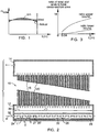
- FIG. 1 illustrates the change in refrigerant distribution along the length of a standard distributor tube commonly used in micro-channel heat exchangers.
- the straight line represents an ideal distribution condition where a refrigerant fluid is evenly distributed - i.e., the refrigerant mass flow does not vary along the length of the distributor tube.
- the curved line in FIG. 1 represents the actual condition of refrigerant distribution. Where the curve lies below the straight line, the actual refrigerant distribution is less than ideal. Where the curve is above the straight line, the actual refrigerant distribution is too high.
- the actual condition curve indicates that tubes in the center of the heat exchanger receive greater fluid flow, while tubes located on the edges of the heat exchanger receive less fluid flow.
- the shadowed area between the two lines indicates the difference between the actual condition and the ideal condition for refrigerant distribution.
- a distributor tube for use in a micro-channel heat exchanger comprises the features of claim 1.
- the non-circular openings are slots disposed along the length of the distributor tube.
- the slots are arranged on the distributor tube so that the longitudinal direction of each slot is angular arranged relative to the longitudinal direction of the distributor tube.
- a micro-channel heat exchanger comprises the features of claim 8, an inlet manifold and an outlet manifold spaced a predetermined distance therefrom.
- a plurality of tubes having opposing ends connected with the inlet manifold and the outlet manifold, respectively, to fluidly connected the inlet manifold and the outlet manifold.
- Each tube includes a plurality of generally parallel micro-channels formed therein.
- a distributor tube as defined in claim 1 is disposed within the inlet manifold and having a first open end adapted to be connected to a refrigerant source and an opposing closed end.
- the distributor tube also includes a plurality of non-circular openings disposed along the length of the distributor tube.
- the plurality of non-circular openings may be arranged in a substantially linear row along the length of the distributor tube, where the row of openings is oriented within the inlet manifold so that the general direction ofrefrigerant flow out of the openings is at an angle relative to the general direction of refrigerant flow through the tubes.
- the distributor tube may comprise two substantially linear rows of non-circular openings along the length of the distributor tube wherein each row of openings is oriented within the inlet manifold so that the refrigerant flow out of the respective openings is angularly disposed relative to the general direction of refrigerant flow through the tubes.
- the present invention has adaptability to a variety of uses, including for evaporators, condensers, gas coolers or heat pumps.
- the present invention has particular utility in air conditioning units for automotive, residential, and light commercial applications. Additionally, the present invention has utility in freezers and conversely heat pump outdoor coils for heating uses.
- FIG. 2 illustrates a heat exchanger design 10 in accordance with the present invention, which provides improved uniformity, or evenness, of refrigerant fluid distribution and improved efficiency of operation.
- the heat exchanger 10 is a micro-channel heat exchanger comprising an inlet manifold 12 fluidly connected with an outlet manifold 14 by a plurality of generally parallel tubes 16.
- the tubes 16 may be flat tubes or circular tubes, and may further be formed to define a plurality of generally parallel micro-channels 18 as more readily seen in FIG. 9 .
- the tubes 16 are connected at both ends to the inlet manifold 12 and the outlet manifold 14, respectively.
- connections are sealed so that the micro-channels 18 can communicate with respective interiors of the inlet manifold 12 and the outlet manifold 14 with no risk of refrigerant fluid leaking out of the heat exchanger 10 during operation.
- a plurality of fins 20 are interposed between adjacent tubes 16, preferably in a zigzagged pattern, to aid in the heat transfer between an airflow passing over the heat exchanger 10 and a refrigerant fluid passing through the heat exchanger 10.
- refrigerant fluid is introduced to the heat exchanger 10 through a distributor tube 22 disposed within the inlet manifold 12.
- the distributor tube 22 generally has a first open end 24 connected to a refrigerant source (not shown) and acting as an inlet for the refrigerant fluid flow, a closed second end 26, and a plurality of openings 28 disposed along the length of the distributor tube 22 and acting as an outlet for the refrigerant fluid flow.
- the refrigerant fluid is discharged from the distributor tube 22 through the openings 28 and into an interior space 30 of the inlet manifold 12.
- the refrigerant fluid is mixed within the inlet manifold 12 so that the gas-phase refrigerant and the liquid-phase refrigerant are blended evenly without stratification phenomenon. Without the distributor tube 22 in the inlet manifold 12 the refrigerant fluid would separate into a liquid-phase and a gas-phase. A blended refrigerant can efficiently flow from the inlet manifold 12 into and through the tubes 16 without two-phase separation.
- openings 28 along the length of the distributor tube 22 aids the blending process within the inlet manifold 12, and also helps distribute the refrigerant fluid to each and every tube 16. Specific features of the distributor tube design that facilitate even dispersal of refrigerant fluid to each of the tubes 16, including the shape, spacing and orientation of the openings 28, are discussed in more detail below.
- refrigerant fluid passes through the tubes 16, an airflow is passed over the surface of the tubes 16 and between the fins 20.
- the refrigerant fluid absorbs heat from the airflow and evaporates.
- the resultant heat from this evaporation cools the airflow.
- the use of the micro-channels 18 increases the efficiency of this heat transfer between the external airflow and the internal refrigerant fluid flow.
- the evaporated refrigerant is passed to the outlet manifold 14 of the heat exchanger 10, where it can be passed on, for example, to a compressor, or recycled through the system.
- the cooled airflow is lowered to a temperature suitable for desired cooling applications, such as in air conditioning units, coolers or freezers.
- the distributor tube 22 is preferably a circular tube, as shown in FIGS. 2 and 9 .
- the tube 22 can have a non-circular cross-sectional shape, such as a square or ellipsoid.
- the refrigerant fluid is introduced to the distributor tube 22 through an inlet 32 along arrow A.
- the inlet 32 is adapted to be connected to a refrigerant source (not shown).
- the distributor tube 22 has a length L, with openings 28 formed in the surface of the tube 22 along the length L. As illustrated, the openings 28 are aligned along the length L of the tube 22 in a substantially linear arrangement. However, alternate embodiments may include openings 28 arranged at various angular orientations around the circumference of the distributor tube 22.
- the distributor tube 22 can be provided with one or more rows of openings 28.
- FIGS. 9 and 10 each illustrate a single row of openings 28, while FIG. 11 illustrates a distributor tube 22 having two rows of openings 28a and 28b.
- the distributor tube 22, the openings 28, the tubes 16, the micro-channels 18, and the interior volume of the inlet manifold 12 may be appropriately sized to provide a desired flow rate of refrigerant fluid, a desired refrigerant fluid distribution pattern, and desired mixing conditions in the heat exchanger 10. Certain relationships and ratios between components may be most preferable to meet predetermined performance criteria. For example, a preferred range of ratios between the sum of the areas of the openings 28 and the surface area of the distributor tube 22 is between about 0.01% to about 40%.
- FIG. 3 illustrates a preferred range for this relationship, where uniformity of refrigerant distribution is at desirable levels if the relationship is designed within the upper and lower bounds shown. More particularly, FIG. 3 shows that for a distributor tube length L in the range of about 0.4 m to about 3 m, the trend of the ratio between total opening area and distributor tube cross-sectional area is between about 0.28 to about 14.4. Moreover, the preferable ratio value and the preferable range of the ratio increase as the length L increases.
- the openings 28 have a non-circular shape.
- the openings 28 are slots or elongated openings, as shown in FIGS. 2 and 4A-4B .
- the openings 28 can be formed by a plurality of intersecting slots extending from a common center, including Y-shaped openings ( FIG. 4C ), X-shaped openings ( FIG. 4D ), crisscross-shaped openings ( FIG. 4E ), and asterisk-shaped openings ( FIGS. 4F-4H ).
- the openings 28 have the form of slots or elongated openings. More specifically, the slots are generally rectangular-shaped having a length l and a width d. In preferred embodiments of the present invention, the openings have a length l in the range of about 1 mm to about 15 mm and a width in the range of about 0.2 mm to about 5 mm.
- the ratio of width to length i.e., d / l ) is preferably greater than about 0.01 and less than about 1. It has been determined that the use of slots provides a level of uniformity that cannot be obtained using circular openings or even non-circular openings having nominal size relative to comparable circular openings.
- FIG. 5 illustrates the effect of the width/length ratio ( d / l ) on the uniformity of refrigerant distribution.
- FIG. 6 illustrates the effect of the slot length ( l ) on the uniformity of refrigerant distribution.
- FIG. 2 illustrates the geometrical centers of adjacent slots.
- the distance L' is between about 20 mm and about 250 mm.
- FIG. 7 illustrates the effect of the distance between adjacent slots (L') on the uniformity of refrigerant distribution. If the distance L' is too small, the refrigerant distribution cannot substantially approach uniformity because there are too many openings 28 distributing refrigerant to the inlet manifold 12.
- Still further improvements in distribution uniformity have been achieved by angling the longitudinal direction of the slots relative to the longitudinal direction of the distributor tube 22. As depicted in FIG. 4B , the slots are arranged at a first angle ⁇ relative to the longitudinal direction of the distributor tube 22.
- FIG. 8 illustrates the effect of the angular orientation ( ⁇ ) of the slot on the uniformity of refrigerant distribution. As shown, the range for the angle ⁇ is between about 0 degrees and 180 degrees.
- Still further improvement in distribution uniformity has been achieved by disposing the slots along the length of the distributor tube 22 so that adjacent slots are angularly arranged relative to the longitudinal direction of the distributor tube 22 in opposing directions. In one alternative of the invention, as depicted in FIG.
- the slots are angularly arranged where by a first slot is inclined at a first angle ⁇ 1 relative to the longitudinal direction of the distributor tube 22 and a second adjacent slot is inclined at a second angle ⁇ 2 relative to the longitudinal direction of the distributor tube 22.
- first angle ⁇ 1 and the second angle ⁇ 2 are equal in magnitude so that two immediately adjacent slots appear as mirror images of one another.
- the angles of adjacent slots can vary between adjacent slots and along the length of the distributor tube 22.
- FIG. 10 a partial cross-sectional view of the micro-channel heat exchanger 10 in accordance with the present invention is shown.
- the distributor tube 22 is shown disposed within the interior space 30 of the inlet manifold 12 such that the openings 28 are directed towards the inlets of the micro-channels 18 of the tubes 16.
- refrigerant fluid is discharged from the distributor tube 22 into the interior space 30 of the inlet manifold 12 through openings 28.
- the refrigerant fluid is typically mixed within the interior space 30 and then distributed into and through the micro-channels 18 of the tubes 16.
- the direction of refrigerant fluid flow out of the openings 28, as represented by arrow 34, is in substantially the same direction as the general refrigerant fluid flow into and through the tubes 16, as represented by arrow 36.
- the direction of refrigerant fluid flow into and through the tubes 16 is the axial direction of the tubes 16.
- angle ⁇ represents the angle between the direction of refrigerant fluid flow out of the openings 28, as represented by arrow 34, and the general direction of refrigerant fluid flow through the tubes 16, as represented by arrow 36.
- the angle ⁇ may be in the range of greater than 0 degrees and less than or equal to 360 degrees.
- the openings 28 may be oriented at an angle ⁇ in the range of greater than or equal to about 90 degrees and less than or equal to about 270 degrees. As illustrated in FIG. 9 , the row of openings 28 is oriented at about 90 degrees.
- FIG. 11 a partial cross-sectional view of the micro-channel heat exchanger 10 using a distributor tube 22 having two rows of openings 28a and 28b is shown.
- a first row of openings 28a may generally be oriented at an angle ⁇ 1 in the range of greater than 0 degrees to less than or equal to 180 degrees.
- a second row of openings 28b may generally be oriented at an angle ⁇ 2 in the range of greater than or equal to 180 degrees and less than 360 degrees.
- the angles ⁇ 1 and ⁇ 2 are preferably equal in magnitude, though they need not be.
- each of the rows of openings 28a and 28b are oriented at approximately 90 degree angles relative to the general direction of the refrigerant fluid flow through the tubes 16.
- heat exchanger 110 includes structure much like the heat exchanger 10 shown in FIG. 2 .
- heat exchanger 110 includes a first manifold 112 fluidly connected with a second manifold 114 by a plurality of generally parallel tubes 116, each preferably comprising a plurality of generally parallel micro-channels (not shown).
- a plurality of fins 118 are interposed between adjacent tubes 116, preferably in a zigzagged pattern, to aid in the heat transfer between an airflow passing over the heat exchanger 110 and a refrigerant fluid passing through the heat exchanger 110.
- the heat exchanger 110 can be designed to have a plurality of flow paths through the heat exchanger 110. Such an exchanger may be useful for applications requiring a long cooling device. Typically, uniformity of refrigerant distribution is difficult to achieve and maintain when the lengths of the manifolds increase.
- One solution previously used in such situations has been to provide a plurality of heat exchangers in a fluid parallel assembly, such as illustrated in U.S. Patent No. 7,143,605 . Such a system, however, increases the number of connections that must be checked to ensure proper operation of the system.
- multiple flow paths through the heat exchanger 110 can be created by providing partitions in one or both of the first manifold 112 and the second manifold 114.
- the partitions divide the manifolds into multiple chambers. As shown in FIG. 12 , the first manifold 112 is divided into three chambers using two partitions 120 and 122.
- the second manifold 114 is divided into two chambers using a single partition 121.
- the heat exchanger 110 includes multiple flow paths that snake back and forth between the first manifold 112 and the second manifold 114.
- Refrigerant flow through the heat exchanger 110 is represented in FIG. 12 by arrows.
- a first chamber 124 of the first manifold 112 defined at one end by the inlet of the first manifold 112 and at the other end by partition 120, receives a first distributor tube 126 having a first open end comprising an inlet 128 for the refrigerant fluid flow, a closed second end, and a plurality of openings 130 disposed along the length of the first distributor tube 126 and acting as an outlet for the refrigerant fluid flow.
- the openings 130 may be slots or other non-circular shapes as described above and shown in FIGS. 2 and 4A-4H .
- the refrigerant fluid is discharged from the first distributor tube 126 through the openings 130 and into the interior space of the first manifold chamber 112 where it is mixed.
- the first chamber 124 acts as a first zone I for the refrigerant flow.
- the refrigerant passes from this zone and into and through the tubes 116.
- the refrigerant is discharged into a first chamber 132 of the second manifold 114.
- the first chamber 132 of the second manifold 114 is generally longer than the first chamber 124 of the first manifold 112, and is essentially divisible into a second zone II and a third zone III .
- the second zone II is generally aligned with and has the same size as the first zone I .
- the second zone II acts as an outlet manifold and receives refrigerant flow from the tubes 116.
- the third zone III acts as an inlet manifold and receives and distributes refrigerant flow discharged from the second zone II .
- a second distributor tube 134 having openings 136 may be disposed in the third zone III for even distribution of refrigerant flow to the tubes 116. Refrigerant then flows from the second manifold 114 through the tubes 116 back to the first manifold 112, where the refrigerant flow is discharged into a second chamber 138 of the first manifold 112.
- the second chamber 138 of the first manifold 112 is longitudinally defined by partitions 120 and 122, and is essentially divisible into a fourth zone IV and a fifth zone V .
- the fourth zone IV is generally aligned with and has the same size as the third zone III .
- the fourth zone IV acts as an outlet manifold and receives refrigerant flow from the tubes 116.
- the fifth zone V acts as an inlet manifold and receives and distributes refrigerant flow from discharged from the fourth zone IV .
- a third distributor tube 140 having openings 142 may be disposed in the fifth zone V for even distribution of refrigerant flow to the tubes 116. Refrigerant then flows from the first manifold 112 through the tubes 116 back to the second manifold 114, where the refrigerant flow is discharged into a second chamber 144 of the second manifold 114.
- the second chamber 144 of the second manifold 114 is longitudinally defined by partition 121 on one end and a closed end of the second manifold 114, and is essentially divisible into a sixth zone VI and a seventh zone VII .
- the sixth zone VI is generally aligned with and has the same size as the fifth zone V .
- the sixth zone VI acts as an outlet manifold and receives refrigerant flow from the tubes 116.
- the seventh zone VII acts as an inlet manifold and receives and distributes refrigerant flow from discharged from the sixth zone VI .
- a fourth distributor tube 146 having openings 148 may be disposed in the seventh zone VII for even distribution of refrigerant flow to the tubes 116. Refrigerant then flows from the second manifold 114 through the tubes 116 back to the first manifold 112, where the refrigerant flow is discharged into a third chamber 150 of the first manifold 112.
- the third chamber 150 of the first manifold 112 is longitudinally defined by partition 122 on one end and an outlet 152 of the first manifold 112 on the other end.
- the third chamber 150 is essentially an eighth zone VIII that is generally aligned with and has the same size as the seventh zone VII .
- the eighth zone VIII acts as an outlet manifold and receives refrigerant flow from the tubes 116 and discharges the refrigerant from the heat exchanger 110.
- the area of the openings therein generally increase so as to account for a decrease flow rate of the refrigerant and an increased flow resistance in the tubes 116.
Landscapes
- Engineering & Computer Science (AREA)
- Physics & Mathematics (AREA)
- Thermal Sciences (AREA)
- Mechanical Engineering (AREA)
- General Engineering & Computer Science (AREA)
- Details Of Heat-Exchange And Heat-Transfer (AREA)
- Heat-Exchange Devices With Radiators And Conduit Assemblies (AREA)
Claims (18)
- Verteilerrohr (22, 126) zur Verwendung in einem Wärmetauscher (10, 110) mit einem Einlasssammler (12, 112), der über eine Vielzahl von im Allgemeinen parallelen Rohren (16, 116) mit einem Auslasssammler (14, 114) fluidisch verbunden ist, wobei das Verteilerrohr (22, 126) aufweist:ein erstes offenes Ende (24), das zur Kommunikation mit einer Kältemittelquelle geeignet ist;ein gegenüberliegendes zweites geschlossenes Ende; undeine Vielzahl von unrunden Öffnungen (28, 130), die entlang der Länge des Verteilerrohrs (22, 126) zwischen dem ersten Ende (24) und dem zweiten Ende (26) angeordnet sind, wobei jede der Vielzahl von Öffnungen (28, 130) ein Schlitz ist, wobei die Längsrichtung von jedem der Schlitze in Bezug auf die Längsrichtung des Verteilerrohres (22, 126) winklig angeordnet ist, wobei benachbarte Schlitze in Bezug auf die Längsrichtung des Verteilerrohrs (22, 126) in entgegengesetzten Richtungen winklig angeordnet sind oder wobei jede der Vielzahl von Öffnungen durch eine Vielzahl von sich schneidenden Schlitzen gebildet ist, die sich von einer gemeinsamen Mitte aus erstrecken.
- Verteilerrohr nach Anspruch 1, wobei die Winkel von benachbarten Schlitzen in Bezug auf die Längsrichtung des Verteilerrohrs (22) im Wesentlichen identisch sind.
- Verteilerrohr nach Anspruch, wobei jeder der Schlitze eine Länge l im Bereich von 1 mm ≤ l ≤ 15 mm aufweist.
- Verteilerrohr nach Anspruch 1, wobei jeder der Schlitze eine Breite d im Bereich von 0,2 mm ≤ d ≤ 5 mm aufweist.
- Verteilerrohr nach Anspruch 1, wobei der geometrische Mittelpunkt von benachbarten Öffnungen durch einen Abstand im Bereich von etwa 20 mm bis etwa 250 mm getrennt ist.
- Verteilerrohr nach Anspruch 1, wobei jede der Vielzahl von Öffnungen (28, 130) drei oder mehr sich schneidende Schlitze aufweist, die sich von einem geometrischen Mittelpunkt aus erstrecken.
- Verteilerrohr nach Anspruch 6, wobei die Form jeder der Vielzahl von Öffnungen (28, 130) eine von einer Y-förmigen Öffnung, einer X-förmigen Öffnung, einer kreuzförmigen Öffnung oder einer sternförmigen Öffnung aufweist.
- Mikrokanal-Wärmetauscher (10), der aufweist:einen Einlasssammler (12);einen Auslasssammler (14), der in einem vorbestimmten Abstand von dem Einlasssammler (12) beabstandet ist;eine Vielzahl von Rohren (16), deren gegenüberliegende Enden mit dem Einlasssammler (12) bzw. dem Auslasssammler (14) verbunden sind, um den Einlasssammler (12) und den Auslasssammler (14) fluidisch miteinander zu verbinden, wobei jedes Rohr (16) eine Vielzahl von im Allgemeinen parallelen Mikrokanälen (18) aufweist, die darin ausgebildet sind, dadurch gekennzeichnet, dass ein Verteilerrohr nach Anspruch 1 innerhalb des Einlasssammlers (12) angeordnet ist.
- Mikrokanal-Wärmetauscher nach Anspruch 8, wobei der Winkel der benachbarten Schlitze in Bezug auf die Längsrichtung des Verteilerrohrs im Allgemeinen identisch sind.
- Mikrokanal-Wärmetauscher nach Anspruch 8, wobei jeder der Schlitze eine Länge l im Bereich von 1 mm ≤ l ≤ 15 mm aufweist.
- Mikrokanal-Wärmetauscher nach Anspruch 8, wobei jeder der Schlitze eine Breite d im Bereich von 0,2 mm ≤ d ≤ 5 mm aufweist.
- Mikrokanal-Wärmetauscher nach Anspruch 8, wobei der geometrische Mittelpunkt benachbarter Öffnungen durch einen Abstand im Bereich von etwa 20 mm bis etwa 250 mm getrennt ist.
- Mikrokanal-Wärmetauscher nach Anspruch 8, wobei jede der Vielzahl von Öffnungen (28) drei oder mehr sich schneidende Schlitze aufweist, die sich von einem geometrischen Mittelpunkt aus erstrecken.
- Mikrokanal-Wärmetauscher nach Anspruch 8, wobei die Vielzahl von Öffnungen (28) in einer im Wesentlichen linearen Reihe entlang der Länge des Verteilerrohres (22) angeordnet ist und
weiterhin, wobei die Reihe von Öffnungen innerhalb des Einlasssammlers (12) so ausgerichtet ist, dass die allgemeine Richtung des Kältemittelflusses aus den Öffnungen in einem Winkel relativ zur allgemeinen Richtung des Kältemittelflusses durch die Rohre (16) liegt. - Mikrokanal-Wärmetauscher nach Anspruch 14, wobei der Winkel im Bereich von größer als oder gleich etwa 90 Grad und kleiner als oder gleich etwa 270 Grad liegt.
- Mikrokanal-Wärmetauscher nach Anspruch 8, wobei das Verteilerrohr (22) zwei im Wesentlichen lineare Reihen von unrunden Öffnungen (28) entlang der Länge L des Verteilerrohrs (22) aufweist, wobei die Ausrichtung der allgemeinen Richtung des Kältemittelflusses aus einer ersten Reihe von Öffnungen (28) relativ zur allgemeinen Richtung des Kältemittelflusses durch die Rohre (16) in einem Winkel im Bereich von mehr als 0 Grad und weniger als oder gleich etwa 180 Grad liegt, und wobei die Ausrichtung der allgemeinen Richtung des Kältemittelflusses aus einer zweiten Reihe von Öffnungen relativ zur allgemeinen Richtung des Kältemittelflusses durch die Rohre (16) in einem Winkel im Bereich von größer als oder gleich etwa 180 Grad und weniger als 360 Grad erfolgt.
- Wärmetauscher (110), durch den ein Kältemittel zirkuliert, der aufweist:
einen ersten Sammler (112):einen zweiten Sammler (114), der in einem vorbestimmten Abstand von dem ersten Sammler (112) beabstandet ist;eine Vielzahl von Rohren (116), deren gegenüberliegende Enden mit dem ersten bzw. zweiten Sammler (112, 114) verbunden sind, um die Sammler (112, 114) fluidisch zu verbinden;mindestens eine Trennwand (120, 121), die radial in mindestens einem der ersten und zweiten Sammler (112, 114) angeordnet ist, um den mindestens einen der ersten und zweiten Sammler (112, 114) in mehrere Längskammern (124, 138; 132, 144) zu trennen, gekennzeichnet durch ein Verteilerohr (126) nach Anspruch 1, der in mindestens einem Abschnitt von mindestens einer der Längskammern (124, 138; 132, 144) auf jeder Seite von jeder Trennwand (120, 121) angeordnet ist. - Wärmetauscher nach Anspruch 17, wobei der erste Sammler (112) eine radial angeordnete Trennwand (120) beinhaltet, die den ersten Sammler in eine erste Längskammer (124) und eine zweite Längskammer (138) unterteilt;
ein erstes Verteilerrohr (126), das innerhalb der ersten Längskammer (124) angeordnet ist und ein erstes offenes Ende (128) aufweist, das mit einer Kältemittelquelle verbunden werden kann, und ein gegenüberliegendes zweites geschlossenes Ende, das innerhalb der ersten Kammer (124) in Richtung der Trennwand gerichtet ist;
wobei das in das erste Verteilerrohr eingeleitete Kältemittel durch die Vielzahl von darin ausgebildeten Öffnungen (130) und in den Innenraum der ersten Kammer (124) entladen werden kann, wobei das Kältemittel danach in und durch eine Vielzahl von Rohren (116) geleitet wird, die mit der ersten Kammer (124) zu dem zweiten Sammler (114) ausgerichtet sind;
wobei ein Abschnitt (III) des zweiten Sammlers (114) ein zweites Verteilerrohr (134) beinhaltet, das darin angeordnet ist, wobei der Abschnitt III im Allgemeinen mit der zweiten Längskammer (138) des ersten Verteilers (112) zur Fluidverbindung damit ausgerichtet ist, wobei das zweite Verteilerrohr (134) ein erstes offenes Ende zur Aufnahme von Kältemittel aus dem zweiten Sammler (114) aufweist, das von der ersten Längskammer (124) des ersten Sammlers (112) zugeführt wird, ein zweites geschlossenes Ende und eine Vielzahl von unrunden Öffnungen (136), die entlang der Länge des zweiten Verteilerrohres (134) angeordnet sind, um Kältemittel zu der Vielzahl von Rohren (116) zuzuführen, die zwischen dem zweiten Sammler (114) und der zweiten Längskammer (138) des ersten Sammlers (112) verbunden sind; und
wobei das in das zweite Verteilerrohr (134) eingeleitete Kältemittel durch die Vielzahl von darin ausgebildeten Öffnungen (136) und in den Innenraum des zweiten Sammlers (114) entladen werden kann, wobei das Kältemittel danach in und durch die Vielzahl der damit ausgerichteten Rohre (116) zur zweiten Kammer (37) des ersten Sammlers (112) gelangt.
Applications Claiming Priority (1)
| Application Number | Priority Date | Filing Date | Title |
|---|---|---|---|
| CN2009101599264A CN101691981B (zh) | 2009-07-23 | 2009-07-23 | 具有改进的制冷剂流体分配均匀性的多通道换热器 |
Publications (3)
| Publication Number | Publication Date |
|---|---|
| EP2278246A2 EP2278246A2 (de) | 2011-01-26 |
| EP2278246A3 EP2278246A3 (de) | 2014-02-12 |
| EP2278246B1 true EP2278246B1 (de) | 2020-01-22 |
Family
ID=41278370
Family Applications (1)
| Application Number | Title | Priority Date | Filing Date |
|---|---|---|---|
| EP09013700.1A Active EP2278246B1 (de) | 2009-07-23 | 2009-10-30 | Verteilerrohr mit gleichmäßiger Kühlflüssigkeitsverteilung |
Country Status (4)
| Country | Link |
|---|---|
| US (2) | US9291407B2 (de) |
| EP (1) | EP2278246B1 (de) |
| KR (3) | KR20110010048A (de) |
| CN (1) | CN101691981B (de) |
Families Citing this family (84)
| Publication number | Priority date | Publication date | Assignee | Title |
|---|---|---|---|---|
| EP2150757B1 (de) * | 2007-05-22 | 2018-10-24 | MAHLE Behr GmbH & Co. KG | Wärmeübertrager |
| US20110240276A1 (en) * | 2010-04-01 | 2011-10-06 | Delphi Technologies, Inc. | Heat exchanger having an inlet distributor and outlet collector |
| CN101858706B (zh) * | 2010-07-01 | 2012-04-25 | 杭州沈氏换热器有限公司 | 一种分液装置 |
| CN101922882B (zh) * | 2010-09-13 | 2011-12-28 | 三花丹佛斯(杭州)微通道换热器有限公司 | 制冷剂导管和具有该制冷剂导管的换热器 |
| CN101922883B (zh) * | 2010-09-13 | 2012-09-26 | 三花控股集团有限公司 | 制冷剂导管和具有该制冷剂导管的换热器 |
| CN101949663B (zh) | 2010-09-13 | 2011-09-28 | 三花丹佛斯(杭州)微通道换热器有限公司 | 制冷剂导管和具有该制冷剂导管的换热器 |
| CN102466426A (zh) * | 2010-11-10 | 2012-05-23 | 北京首航艾启威节能技术股份有限公司 | 一种带有导流片的空冷器管箱 |
| CN102564204B (zh) * | 2010-12-08 | 2016-04-06 | 杭州三花微通道换热器有限公司 | 制冷剂分配装置和具有它的换热器 |
| CN102079038B (zh) | 2010-12-08 | 2013-02-13 | 三花控股集团有限公司 | 一种换热器及其制冷剂导流管,以及制冷剂导流管的加工方法 |
| JP5626198B2 (ja) * | 2010-12-28 | 2014-11-19 | 株式会社デンソー | 冷媒放熱器 |
| CN102072684B (zh) * | 2011-01-06 | 2012-10-17 | 三花控股集团有限公司 | 制冷剂分配装置和具有它的换热器 |
| CH704446A1 (de) * | 2011-02-02 | 2012-08-15 | Alstom Technology Ltd | Wärmeübertragungsanordnung. |
| CN102252559B (zh) * | 2011-05-20 | 2013-02-13 | 广东美的制冷设备有限公司 | 微通道换热器及其制作方法 |
| CN103635771A (zh) | 2011-06-27 | 2014-03-12 | 开利公司 | 微孔壳管式换热器 |
| CN102297547B (zh) * | 2011-06-27 | 2013-04-10 | 三花控股集团有限公司 | 换热器 |
| CN102230697B (zh) * | 2011-07-01 | 2013-02-13 | Tcl空调器(中山)有限公司 | 空调换热器 |
| CN102313400A (zh) * | 2011-07-21 | 2012-01-11 | 广东美的电器股份有限公司 | 微通道平行流换热器 |
| CN102435021A (zh) * | 2011-09-18 | 2012-05-02 | Tcl空调器(中山)有限公司 | 一种蒸发器及其流程设计方法 |
| US8739855B2 (en) | 2012-02-17 | 2014-06-03 | Hussmann Corporation | Microchannel heat exchanger |
| JP5897359B2 (ja) * | 2012-03-13 | 2016-03-30 | 東レ・メディカル株式会社 | 人工鼻 |
| CN103363734B (zh) * | 2012-04-10 | 2015-12-02 | 珠海格力电器股份有限公司 | 分液装置及包括该分液装置的空调器 |
| CN103363731A (zh) * | 2012-04-10 | 2013-10-23 | 珠海格力电器股份有限公司 | 分液装置及包括该分液装置的空调器 |
| CN103363725A (zh) * | 2012-04-10 | 2013-10-23 | 珠海格力电器股份有限公司 | 微通道换热器及包括该微通道换热器的空调器 |
| WO2013190617A1 (ja) * | 2012-06-18 | 2013-12-27 | 三菱電機株式会社 | 熱交換器 |
| US9115938B2 (en) | 2012-06-20 | 2015-08-25 | Hamilton Sundstrand Corporation | Two-phase distributor |
| DE102012217340A1 (de) * | 2012-09-25 | 2014-03-27 | Behr Gmbh & Co. Kg | Wärmeübertrager |
| CN102927722A (zh) * | 2012-09-27 | 2013-02-13 | 浙江盾安人工环境股份有限公司 | 微通道蒸发器及包含其的空调器 |
| US9746255B2 (en) * | 2012-11-16 | 2017-08-29 | Mahle International Gmbh | Heat pump heat exchanger having a low pressure drop distribution tube |
| US9459057B2 (en) * | 2013-01-24 | 2016-10-04 | Alcoll USA LLC | Heat exchanger |
| KR20140116626A (ko) | 2013-03-25 | 2014-10-06 | 엘지전자 주식회사 | 열교환기 |
| CN105229404B (zh) * | 2013-05-15 | 2018-07-17 | 三菱电机株式会社 | 层叠型联管箱、热交换器和空气调节装置 |
| CN103486896B (zh) * | 2013-07-30 | 2015-05-27 | 杭州三花微通道换热器有限公司 | 集流管组件和具有该集流管组件的换热器 |
| US9989283B2 (en) | 2013-08-12 | 2018-06-05 | Carrier Corporation | Heat exchanger and flow distributor |
| CN103438750B (zh) * | 2013-09-17 | 2016-08-24 | 杭州三花微通道换热器有限公司 | 一种热交换器及其集流管组件 |
| WO2015073106A1 (en) * | 2013-11-18 | 2015-05-21 | Carrier Corporation | Flash gas bypass evaporator |
| CN104048548B (zh) * | 2014-05-26 | 2016-01-27 | 杭州三花微通道换热器有限公司 | 可调节的制冷剂分配装置和具有它的换热器 |
| US10168083B2 (en) * | 2014-07-11 | 2019-01-01 | Hangzhou Sanhua Research Institute Co., Ltd. | Refrigeration system and heat exchanger thereof |
| JP2016023815A (ja) * | 2014-07-16 | 2016-02-08 | 株式会社ケーヒン・サーマル・テクノロジー | エバポレータ |
| US10184703B2 (en) | 2014-08-19 | 2019-01-22 | Carrier Corporation | Multipass microchannel heat exchanger |
| EP3537088B1 (de) | 2014-08-19 | 2022-10-26 | Carrier Corporation | Mikrokanalwärmetauscher mit niedriger kühlmittelladung |
| US10197312B2 (en) * | 2014-08-26 | 2019-02-05 | Mahle International Gmbh | Heat exchanger with reduced length distributor tube |
| US10072900B2 (en) * | 2014-09-16 | 2018-09-11 | Mahle International Gmbh | Heat exchanger distributor with intersecting streams |
| CN104457383A (zh) * | 2014-12-15 | 2015-03-25 | 重庆东京散热器有限公司 | 一种油冷器用油室 |
| US20160231067A1 (en) * | 2015-02-09 | 2016-08-11 | Delphi Technologies, Inc. | Heat exchanger with clam-shell header |
| US9915456B2 (en) | 2015-06-03 | 2018-03-13 | Mitsubishi Electric Research Laboratories, Inc. | System and method for controlling vapor compression systems |
| US20170045309A1 (en) * | 2015-08-11 | 2017-02-16 | Hamilton Sundstrand Corporation | High temperature flow manifold |
| CN106556184B (zh) * | 2015-09-28 | 2019-07-30 | 曼德电子电器有限公司 | 蒸发器和空调系统 |
| JP6617003B2 (ja) * | 2015-10-30 | 2019-12-04 | 株式会社ケーヒン・サーマル・テクノロジー | 熱交換器 |
| US10551099B2 (en) | 2016-02-04 | 2020-02-04 | Mahle International Gmbh | Micro-channel evaporator having compartmentalized distribution |
| US9909822B2 (en) * | 2016-02-08 | 2018-03-06 | Hamilton Sundstrand Corporation | Channel guide distributor |
| EP3452771B1 (de) * | 2016-05-03 | 2022-08-31 | Carrier Corporation | Wärmetauscheranordnung |
| US10059103B2 (en) * | 2016-05-27 | 2018-08-28 | Sii Printek Inc. | Liquid jet head and liquid jet apparatus |
| CN106123409B (zh) * | 2016-08-22 | 2018-09-11 | 杭州三花微通道换热器有限公司 | 制冷剂分配装置和平行流换热器 |
| FR3059407B1 (fr) * | 2016-11-30 | 2019-10-18 | Valeo Systemes Thermiques | Dispositif de mixage d'un fluide refrigerant a l'interieur d'une boite collectrice d'un echangeur thermique |
| CN207113692U (zh) * | 2016-12-30 | 2018-03-16 | 杭州三花微通道换热器有限公司 | 集流管和具有其的换热器 |
| JP6746234B2 (ja) * | 2017-01-25 | 2020-08-26 | 日立ジョンソンコントロールズ空調株式会社 | 熱交換器、及び、空気調和機 |
| CN106839530A (zh) * | 2017-03-21 | 2017-06-13 | 昆山方佳机械制造有限公司 | 一种干式蒸发器 |
| JP6419882B2 (ja) * | 2017-03-29 | 2018-11-07 | 日立ジョンソンコントロールズ空調株式会社 | 空気調和機 |
| US11614260B2 (en) | 2017-05-05 | 2023-03-28 | Carrier Corporation | Heat exchanger for heat pump applications |
| US10760834B2 (en) * | 2018-09-05 | 2020-09-01 | Audi Ag | Evaporator in a refrigerant circuit D |
| US10760833B2 (en) * | 2018-09-05 | 2020-09-01 | Audi Ag | Evaporator in a refrigerant circuit c |
| US10760835B2 (en) * | 2018-09-05 | 2020-09-01 | Audi Ag | Evaporator in a refrigerant circuit E |
| CN110966804B (zh) * | 2018-09-30 | 2021-09-24 | 浙江三花智能控制股份有限公司 | 换热器 |
| CN109539634B (zh) * | 2018-12-03 | 2020-04-28 | 珠海格力电器股份有限公司 | 一种微通道换热器及空调器 |
| US12339066B2 (en) * | 2018-12-06 | 2025-06-24 | Tyco Fire & Security Gmbh | Microchannel heat exchanger with varying fin density |
| PL3671067T3 (pl) * | 2018-12-17 | 2023-01-16 | Valeo Autosystemy Sp. Z.O.O. | Wymiennik ciepła |
| DE102018222815A1 (de) * | 2018-12-21 | 2020-06-25 | Mahle International Gmbh | Aufnahmekasten für eine Wärmeübertrager |
| CN111442571B (zh) * | 2019-01-17 | 2022-03-25 | 浙江三花智能控制股份有限公司 | 集流管组件和换热器 |
| US11713931B2 (en) | 2019-05-02 | 2023-08-01 | Carrier Corporation | Multichannel evaporator distributor |
| EP3978856B1 (de) * | 2019-06-05 | 2024-03-20 | Hisaka Works, Ltd. | Plattenwärmetauscher und verteiler für plattenwärmetauscher |
| CN110444519A (zh) * | 2019-06-26 | 2019-11-12 | 南昌大学 | 一种具有多流道相联通的微通道换热器 |
| EP3855059B1 (de) * | 2020-01-24 | 2023-11-15 | Aptiv Technologies Limited | Passiver strömungsteiler und flüssigkeitskühlsystem damit |
| US11519670B2 (en) | 2020-02-11 | 2022-12-06 | Airborne ECS, LLC | Microtube heat exchanger devices, systems and methods |
| US11408688B2 (en) * | 2020-06-17 | 2022-08-09 | Mahle International Gmbh | Heat exchanger |
| CN120846110A (zh) * | 2020-09-29 | 2025-10-28 | 台达电子工业股份有限公司 | 水冷装置及其集流器 |
| CN112696334A (zh) * | 2021-01-04 | 2021-04-23 | 南宁市安和机械设备有限公司 | 一种错位打点管制成的空压机散热器 |
| DE102021102360A1 (de) * | 2021-02-02 | 2022-08-04 | Lisa Dräxlmaier GmbH | Batteriemodulgehäuse und anordnung von batteriemodulen |
| CN113007928A (zh) * | 2021-03-25 | 2021-06-22 | 青岛海尔空调器有限总公司 | 帽状分流元件和流体分配器 |
| US12416453B1 (en) | 2021-07-22 | 2025-09-16 | Intergalactic Spaceworx, LLC | Heat exchange header with refrigerant distribution by capillary wicking porous insert |
| JP7142806B1 (ja) * | 2021-10-15 | 2022-09-27 | 三菱電機株式会社 | 分配器、熱交換器およびヒートポンプ装置 |
| US12270583B2 (en) * | 2021-12-07 | 2025-04-08 | Rheem Manufacturing Company | Distributor systems for heat exchangers |
| CN117663885A (zh) * | 2022-08-25 | 2024-03-08 | 浙江盾安热工科技有限公司 | 换热器及空调设备 |
| CN115993020B (zh) * | 2022-12-07 | 2025-12-23 | 西安交通大学 | 一种与流量适配的微通道蒸发器及其控制方法 |
| WO2024257145A1 (ja) * | 2023-06-12 | 2024-12-19 | 三菱電機株式会社 | 熱交換器及び空気調和装置 |
Family Cites Families (31)
| Publication number | Priority date | Publication date | Assignee | Title |
|---|---|---|---|---|
| US528144A (en) * | 1894-10-30 | Combined fountain and sprinkler | ||
| US1684083A (en) * | 1927-06-02 | 1928-09-11 | Samuel C Bloom | Refrigerating coil |
| US1966572A (en) * | 1932-07-29 | 1934-07-17 | Colt S Mfg Co | Jet device for washing machines |
| US2759248A (en) * | 1950-06-22 | 1956-08-21 | Russell H Burgess | Method of making heat transfer units |
| US4335782A (en) * | 1974-07-01 | 1982-06-22 | The Garrett Corporation | Heat exchanger method |
| US3976128A (en) * | 1975-06-12 | 1976-08-24 | Ford Motor Company | Plate and fin heat exchanger |
| DE3311579C2 (de) * | 1983-03-30 | 1985-10-03 | Süddeutsche Kühlerfabrik Julius Fr. Behr GmbH & Co. KG, 7000 Stuttgart | Wärmetauscher |
| JPS6030971U (ja) * | 1983-08-08 | 1985-03-02 | カルソニックカンセイ株式会社 | 異形管エバポレ−タ |
| US5099576A (en) * | 1989-08-29 | 1992-03-31 | Sanden Corporation | Heat exchanger and method for manufacturing the heat exchanger |
| KR0143540B1 (ko) * | 1992-08-27 | 1998-08-01 | 코오노 미찌아끼 | 편평튜브와 물결형휜을 교호로 적층해서 이루어진 적층형 열교환기 및 그 제조방법 |
| JP3332428B2 (ja) | 1992-11-30 | 2002-10-07 | 昭和電工株式会社 | 積層型凝縮器及びその製造方法 |
| JPH09166368A (ja) | 1995-12-14 | 1997-06-24 | Sanden Corp | 熱交換器 |
| JP3879032B2 (ja) | 1997-03-27 | 2007-02-07 | 三菱電機株式会社 | 冷却装置 |
| US5850732A (en) * | 1997-05-13 | 1998-12-22 | Capstone Turbine Corporation | Low emissions combustion system for a gas turbine engine |
| US5910167A (en) * | 1997-10-20 | 1999-06-08 | Modine Manufacturing Co. | Inlet for an evaporator |
| FR2770896B1 (fr) * | 1997-11-10 | 2000-01-28 | Valeo Thermique Moteur Sa | Condenseur de climatisation muni d'un reservoir de fluide a cartouche interchangeable |
| DE19911334A1 (de) * | 1999-03-15 | 2000-09-21 | Behr Gmbh & Co | Sammelrohr für einen Wärmeübertrager und Herstellungsverfahren hierfür |
| US6729386B1 (en) * | 2001-01-22 | 2004-05-04 | Stanley H. Sather | Pulp drier coil with improved header |
| US7017656B2 (en) * | 2001-05-24 | 2006-03-28 | Honeywell International, Inc. | Heat exchanger with manifold tubes for stiffening and load bearing |
| US6814136B2 (en) * | 2002-08-06 | 2004-11-09 | Visteon Global Technologies, Inc. | Perforated tube flow distributor |
| JP2004278935A (ja) | 2003-03-17 | 2004-10-07 | Calsonic Kansei Corp | 蒸発器 |
| EP1548380A3 (de) * | 2003-12-22 | 2006-10-04 | Hussmann Corporation | Flachrohrverdampfer mit Mikroverteiler |
| US20070256821A1 (en) * | 2004-09-08 | 2007-11-08 | Calsonic Kansei Corporation | Header Tank for Heat Exchanger |
| MX2007009246A (es) * | 2005-02-02 | 2007-09-04 | Carrier Corp | Insercion de tubo y disposicion de doble flujo para un colector de una bomba de calor. |
| US20080023185A1 (en) * | 2006-07-25 | 2008-01-31 | Henry Earl Beamer | Heat exchanger assembly |
| US7946036B2 (en) * | 2006-09-28 | 2011-05-24 | Delphi Technologies, Inc. | Method of manufacturing a manifold for a heat exchanger |
| ES2384185T3 (es) | 2006-10-13 | 2012-07-02 | Carrier Corporation | Método y aparato para mejorar la distribución de fluido en un intercambiador de calor |
| ATE556283T1 (de) | 2006-10-13 | 2012-05-15 | Carrier Corp | Mehrzügige wärmetauscher mit verteileinsätze aufweisenden rückführendkammern |
| US8171987B2 (en) * | 2006-11-13 | 2012-05-08 | Carrier Corporation | Minichannel heat exchanger header insert for distribution |
| US7921558B2 (en) * | 2008-01-09 | 2011-04-12 | Delphi Technologies, Inc. | Non-cylindrical refrigerant conduit and method of making same |
| CN101839590B (zh) * | 2010-02-22 | 2012-03-21 | 三花丹佛斯(杭州)微通道换热器有限公司 | 一种微通道换热器 |
-
2009
- 2009-07-23 CN CN2009101599264A patent/CN101691981B/zh active Active
- 2009-08-04 US US12/535,504 patent/US9291407B2/en active Active - Reinstated
- 2009-10-30 EP EP09013700.1A patent/EP2278246B1/de active Active
-
2010
- 2010-03-25 KR KR1020100026722A patent/KR20110010048A/ko not_active Ceased
-
2012
- 2012-08-17 KR KR1020120090013A patent/KR20120104505A/ko not_active Ceased
-
2013
- 2013-05-15 KR KR1020130054976A patent/KR101338283B1/ko not_active Expired - Fee Related
-
2015
- 2015-09-08 US US14/847,302 patent/US20150377566A1/en not_active Abandoned
Non-Patent Citations (1)
| Title |
|---|
| None * |
Also Published As
| Publication number | Publication date |
|---|---|
| US20150377566A1 (en) | 2015-12-31 |
| US9291407B2 (en) | 2016-03-22 |
| KR101338283B1 (ko) | 2013-12-09 |
| EP2278246A2 (de) | 2011-01-26 |
| KR20120104505A (ko) | 2012-09-21 |
| CN101691981B (zh) | 2011-12-07 |
| KR20130069687A (ko) | 2013-06-26 |
| CN101691981A (zh) | 2010-04-07 |
| EP2278246A3 (de) | 2014-02-12 |
| KR20110010048A (ko) | 2011-01-31 |
| US20110017438A1 (en) | 2011-01-27 |
Similar Documents
| Publication | Publication Date | Title |
|---|---|---|
| EP2278246B1 (de) | Verteilerrohr mit gleichmäßiger Kühlflüssigkeitsverteilung | |
| EP2079973B1 (de) | Mehrzügige wärmetauscher mit verteileinsätze aufweisenden rückführendkammern | |
| EP2082181B1 (de) | Parallelstromwärmetauscher | |
| KR100908769B1 (ko) | 병류 열교환기와, 균일한 냉매 유동을 촉진하는 방법 | |
| EP2853843B1 (de) | Kältemittelverteiler und wärmetauscher mit dem kältemittelverteiler | |
| EP3779346B1 (de) | Verteiler und wärmetauscher | |
| US20080190134A1 (en) | Refrigerant flow distributor | |
| CN105209846B (zh) | 热交换器 | |
| US10161686B2 (en) | Microchanel heat exchanger evaporator | |
| EP1844287B1 (de) | Minikanal-wärmetauscher-endkammer | |
| EP3619492B1 (de) | Wärmetauscher für wärmepumpenanwendungen | |
| EP2724107B1 (de) | Mantel und röhrenwärmetauscher mit mikrokanäle | |
| CN201522230U (zh) | 分配管和具有该分配管的换热器 | |
| US20250137738A1 (en) | Microchannel heat exchanger | |
| US20250283673A1 (en) | Laminated header for a microchannel heat exchanger | |
| CN114688765A (zh) | 换热器和空调器 | |
| US20250230995A1 (en) | Fluid distributor for a heat exchanger | |
| HK1138362B (en) | Multi-pass heat exchangers having return manifolds with distributing inserts |
Legal Events
| Date | Code | Title | Description |
|---|---|---|---|
| PUAI | Public reference made under article 153(3) epc to a published international application that has entered the european phase |
Free format text: ORIGINAL CODE: 0009012 |
|
| AK | Designated contracting states |
Kind code of ref document: A2 Designated state(s): AT BE BG CH CY CZ DE DK EE ES FI FR GB GR HR HU IE IS IT LI LT LU LV MC MK MT NL NO PL PT RO SE SI SK SM TR |
|
| AX | Request for extension of the european patent |
Extension state: AL BA RS |
|
| 17P | Request for examination filed |
Effective date: 20120727 |
|
| RAP1 | Party data changed (applicant data changed or rights of an application transferred) |
Owner name: DANFOSS A/S Owner name: SANHUA HOLDING GROUP CO., LTD. |
|
| PUAL | Search report despatched |
Free format text: ORIGINAL CODE: 0009013 |
|
| AK | Designated contracting states |
Kind code of ref document: A3 Designated state(s): AT BE BG CH CY CZ DE DK EE ES FI FR GB GR HR HU IE IS IT LI LT LU LV MC MK MT NL NO PL PT RO SE SI SK SM TR |
|
| AX | Request for extension of the european patent |
Extension state: AL BA RS |
|
| RIC1 | Information provided on ipc code assigned before grant |
Ipc: F28F 9/02 20060101ALI20140109BHEP Ipc: F25B 39/02 20060101ALI20140109BHEP Ipc: F28D 1/053 20060101AFI20140109BHEP |
|
| RAP1 | Party data changed (applicant data changed or rights of an application transferred) |
Owner name: DANFOSS A/S Owner name: SANHUA (HANGZHOU) MICRO CHANNEL HEAT EXCHANGER CO. |
|
| STAA | Information on the status of an ep patent application or granted ep patent |
Free format text: STATUS: EXAMINATION IS IN PROGRESS |
|
| 17Q | First examination report despatched |
Effective date: 20170222 |
|
| GRAP | Despatch of communication of intention to grant a patent |
Free format text: ORIGINAL CODE: EPIDOSNIGR1 |
|
| STAA | Information on the status of an ep patent application or granted ep patent |
Free format text: STATUS: GRANT OF PATENT IS INTENDED |
|
| INTG | Intention to grant announced |
Effective date: 20190917 |
|
| GRAS | Grant fee paid |
Free format text: ORIGINAL CODE: EPIDOSNIGR3 |
|
| GRAA | (expected) grant |
Free format text: ORIGINAL CODE: 0009210 |
|
| STAA | Information on the status of an ep patent application or granted ep patent |
Free format text: STATUS: THE PATENT HAS BEEN GRANTED |
|
| AK | Designated contracting states |
Kind code of ref document: B1 Designated state(s): AT BE BG CH CY CZ DE DK EE ES FI FR GB GR HR HU IE IS IT LI LT LU LV MC MK MT NL NO PL PT RO SE SI SK SM TR |
|
| REG | Reference to a national code |
Ref country code: GB Ref legal event code: FG4D |
|
| REG | Reference to a national code |
Ref country code: CH Ref legal event code: EP |
|
| REG | Reference to a national code |
Ref country code: DE Ref legal event code: R096 Ref document number: 602009061042 Country of ref document: DE |
|
| REG | Reference to a national code |
Ref country code: AT Ref legal event code: REF Ref document number: 1227172 Country of ref document: AT Kind code of ref document: T Effective date: 20200215 |
|
| REG | Reference to a national code |
Ref country code: IE Ref legal event code: FG4D |
|
| REG | Reference to a national code |
Ref country code: NL Ref legal event code: MP Effective date: 20200122 |
|
| REG | Reference to a national code |
Ref country code: LT Ref legal event code: MG4D |
|
| PG25 | Lapsed in a contracting state [announced via postgrant information from national office to epo] |
Ref country code: PT Free format text: LAPSE BECAUSE OF FAILURE TO SUBMIT A TRANSLATION OF THE DESCRIPTION OR TO PAY THE FEE WITHIN THE PRESCRIBED TIME-LIMIT Effective date: 20200614 Ref country code: NL Free format text: LAPSE BECAUSE OF FAILURE TO SUBMIT A TRANSLATION OF THE DESCRIPTION OR TO PAY THE FEE WITHIN THE PRESCRIBED TIME-LIMIT Effective date: 20200122 Ref country code: NO Free format text: LAPSE BECAUSE OF FAILURE TO SUBMIT A TRANSLATION OF THE DESCRIPTION OR TO PAY THE FEE WITHIN THE PRESCRIBED TIME-LIMIT Effective date: 20200422 Ref country code: FI Free format text: LAPSE BECAUSE OF FAILURE TO SUBMIT A TRANSLATION OF THE DESCRIPTION OR TO PAY THE FEE WITHIN THE PRESCRIBED TIME-LIMIT Effective date: 20200122 |
|
| PG25 | Lapsed in a contracting state [announced via postgrant information from national office to epo] |
Ref country code: IS Free format text: LAPSE BECAUSE OF FAILURE TO SUBMIT A TRANSLATION OF THE DESCRIPTION OR TO PAY THE FEE WITHIN THE PRESCRIBED TIME-LIMIT Effective date: 20200522 Ref country code: GR Free format text: LAPSE BECAUSE OF FAILURE TO SUBMIT A TRANSLATION OF THE DESCRIPTION OR TO PAY THE FEE WITHIN THE PRESCRIBED TIME-LIMIT Effective date: 20200423 Ref country code: SE Free format text: LAPSE BECAUSE OF FAILURE TO SUBMIT A TRANSLATION OF THE DESCRIPTION OR TO PAY THE FEE WITHIN THE PRESCRIBED TIME-LIMIT Effective date: 20200122 Ref country code: LV Free format text: LAPSE BECAUSE OF FAILURE TO SUBMIT A TRANSLATION OF THE DESCRIPTION OR TO PAY THE FEE WITHIN THE PRESCRIBED TIME-LIMIT Effective date: 20200122 Ref country code: HR Free format text: LAPSE BECAUSE OF FAILURE TO SUBMIT A TRANSLATION OF THE DESCRIPTION OR TO PAY THE FEE WITHIN THE PRESCRIBED TIME-LIMIT Effective date: 20200122 Ref country code: BG Free format text: LAPSE BECAUSE OF FAILURE TO SUBMIT A TRANSLATION OF THE DESCRIPTION OR TO PAY THE FEE WITHIN THE PRESCRIBED TIME-LIMIT Effective date: 20200422 |
|
| REG | Reference to a national code |
Ref country code: DE Ref legal event code: R097 Ref document number: 602009061042 Country of ref document: DE |
|
| PG25 | Lapsed in a contracting state [announced via postgrant information from national office to epo] |
Ref country code: DK Free format text: LAPSE BECAUSE OF FAILURE TO SUBMIT A TRANSLATION OF THE DESCRIPTION OR TO PAY THE FEE WITHIN THE PRESCRIBED TIME-LIMIT Effective date: 20200122 Ref country code: ES Free format text: LAPSE BECAUSE OF FAILURE TO SUBMIT A TRANSLATION OF THE DESCRIPTION OR TO PAY THE FEE WITHIN THE PRESCRIBED TIME-LIMIT Effective date: 20200122 Ref country code: EE Free format text: LAPSE BECAUSE OF FAILURE TO SUBMIT A TRANSLATION OF THE DESCRIPTION OR TO PAY THE FEE WITHIN THE PRESCRIBED TIME-LIMIT Effective date: 20200122 Ref country code: LT Free format text: LAPSE BECAUSE OF FAILURE TO SUBMIT A TRANSLATION OF THE DESCRIPTION OR TO PAY THE FEE WITHIN THE PRESCRIBED TIME-LIMIT Effective date: 20200122 Ref country code: SM Free format text: LAPSE BECAUSE OF FAILURE TO SUBMIT A TRANSLATION OF THE DESCRIPTION OR TO PAY THE FEE WITHIN THE PRESCRIBED TIME-LIMIT Effective date: 20200122 Ref country code: SK Free format text: LAPSE BECAUSE OF FAILURE TO SUBMIT A TRANSLATION OF THE DESCRIPTION OR TO PAY THE FEE WITHIN THE PRESCRIBED TIME-LIMIT Effective date: 20200122 Ref country code: RO Free format text: LAPSE BECAUSE OF FAILURE TO SUBMIT A TRANSLATION OF THE DESCRIPTION OR TO PAY THE FEE WITHIN THE PRESCRIBED TIME-LIMIT Effective date: 20200122 Ref country code: CZ Free format text: LAPSE BECAUSE OF FAILURE TO SUBMIT A TRANSLATION OF THE DESCRIPTION OR TO PAY THE FEE WITHIN THE PRESCRIBED TIME-LIMIT Effective date: 20200122 |
|
| REG | Reference to a national code |
Ref country code: AT Ref legal event code: MK05 Ref document number: 1227172 Country of ref document: AT Kind code of ref document: T Effective date: 20200122 |
|
| PLBE | No opposition filed within time limit |
Free format text: ORIGINAL CODE: 0009261 |
|
| STAA | Information on the status of an ep patent application or granted ep patent |
Free format text: STATUS: NO OPPOSITION FILED WITHIN TIME LIMIT |
|
| 26N | No opposition filed |
Effective date: 20201023 |
|
| PG25 | Lapsed in a contracting state [announced via postgrant information from national office to epo] |
Ref country code: AT Free format text: LAPSE BECAUSE OF FAILURE TO SUBMIT A TRANSLATION OF THE DESCRIPTION OR TO PAY THE FEE WITHIN THE PRESCRIBED TIME-LIMIT Effective date: 20200122 |
|
| PG25 | Lapsed in a contracting state [announced via postgrant information from national office to epo] |
Ref country code: SI Free format text: LAPSE BECAUSE OF FAILURE TO SUBMIT A TRANSLATION OF THE DESCRIPTION OR TO PAY THE FEE WITHIN THE PRESCRIBED TIME-LIMIT Effective date: 20200122 Ref country code: PL Free format text: LAPSE BECAUSE OF FAILURE TO SUBMIT A TRANSLATION OF THE DESCRIPTION OR TO PAY THE FEE WITHIN THE PRESCRIBED TIME-LIMIT Effective date: 20200122 |
|
| REG | Reference to a national code |
Ref country code: CH Ref legal event code: PL |
|
| GBPC | Gb: european patent ceased through non-payment of renewal fee |
Effective date: 20201030 |
|
| PG25 | Lapsed in a contracting state [announced via postgrant information from national office to epo] |
Ref country code: MC Free format text: LAPSE BECAUSE OF FAILURE TO SUBMIT A TRANSLATION OF THE DESCRIPTION OR TO PAY THE FEE WITHIN THE PRESCRIBED TIME-LIMIT Effective date: 20200122 Ref country code: LU Free format text: LAPSE BECAUSE OF NON-PAYMENT OF DUE FEES Effective date: 20201030 |
|
| REG | Reference to a national code |
Ref country code: BE Ref legal event code: MM Effective date: 20201031 |
|
| PG25 | Lapsed in a contracting state [announced via postgrant information from national office to epo] |
Ref country code: LI Free format text: LAPSE BECAUSE OF NON-PAYMENT OF DUE FEES Effective date: 20201031 Ref country code: GB Free format text: LAPSE BECAUSE OF NON-PAYMENT OF DUE FEES Effective date: 20201030 Ref country code: CH Free format text: LAPSE BECAUSE OF NON-PAYMENT OF DUE FEES Effective date: 20201031 Ref country code: BE Free format text: LAPSE BECAUSE OF NON-PAYMENT OF DUE FEES Effective date: 20201031 |
|
| PG25 | Lapsed in a contracting state [announced via postgrant information from national office to epo] |
Ref country code: IE Free format text: LAPSE BECAUSE OF NON-PAYMENT OF DUE FEES Effective date: 20201030 |
|
| PG25 | Lapsed in a contracting state [announced via postgrant information from national office to epo] |
Ref country code: TR Free format text: LAPSE BECAUSE OF FAILURE TO SUBMIT A TRANSLATION OF THE DESCRIPTION OR TO PAY THE FEE WITHIN THE PRESCRIBED TIME-LIMIT Effective date: 20200122 Ref country code: MT Free format text: LAPSE BECAUSE OF FAILURE TO SUBMIT A TRANSLATION OF THE DESCRIPTION OR TO PAY THE FEE WITHIN THE PRESCRIBED TIME-LIMIT Effective date: 20200122 Ref country code: CY Free format text: LAPSE BECAUSE OF FAILURE TO SUBMIT A TRANSLATION OF THE DESCRIPTION OR TO PAY THE FEE WITHIN THE PRESCRIBED TIME-LIMIT Effective date: 20200122 |
|
| PG25 | Lapsed in a contracting state [announced via postgrant information from national office to epo] |
Ref country code: MK Free format text: LAPSE BECAUSE OF FAILURE TO SUBMIT A TRANSLATION OF THE DESCRIPTION OR TO PAY THE FEE WITHIN THE PRESCRIBED TIME-LIMIT Effective date: 20200122 |
|
| REG | Reference to a national code |
Ref country code: DE Ref legal event code: R081 Ref document number: 602009061042 Country of ref document: DE Owner name: SANHUA (HANGZHOU) MICRO CHANNEL HEAT EXCHANGER, CN Free format text: FORMER OWNERS: DANFOSS A/S, NORDBORG, DK; SANHUA (HANGZHOU) MICRO CHANNEL HEAT EXCHANGER CO. LTD., HANGZHOU, ZHEJIANG, CN |
|
| P01 | Opt-out of the competence of the unified patent court (upc) registered |
Effective date: 20230601 |
|
| PGFP | Annual fee paid to national office [announced via postgrant information from national office to epo] |
Ref country code: DE Payment date: 20251030 Year of fee payment: 17 |
|
| PGFP | Annual fee paid to national office [announced via postgrant information from national office to epo] |
Ref country code: IT Payment date: 20251024 Year of fee payment: 17 |
|
| PGFP | Annual fee paid to national office [announced via postgrant information from national office to epo] |
Ref country code: FR Payment date: 20251024 Year of fee payment: 17 |